1
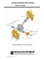
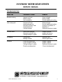
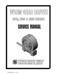
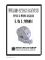
PO Box 645, Stockton, Missouri, 65785 1-800-346-5745
417-276-5191 FAX 417-276-3492 superiorgearbox.com
W000-7000-D0446-A 4/1/05
1
V210/W260 WORM GEAR DRIVES
SERVICE MANUAL
SAFETY PRECAUTIONS
CAUTION
Please read this entire document prior to operating the gear drive. Gear drive failure and / or
injury to operators may be caused by improper installation, operation or maintenance.
The buyer shall be responsible to:
• Determine if the gear drive selected is mechanically adequate for the chosen application
and to verify that published catalog capacities are not exceeded.
• Ensure that all connected rotating parts in the system are free from critical torsional or any
other type vibration.
• Eliminate any obstruction to cooling airflow when mounting the gear drive. Also consider
any accumulation of external debris which could reduce cooling airflow over the unit during
operation.
INSTALLATION
Gear drives must be mounted on a rigid, structurally sound baseplate. Flatness within 0.010
in. is recommended. Ensure that gear drive mounting pads rest evenly on the baseplate. The
use of shims may be required to avoid housing distortion which could alter the gear mesh or
cause premature bearing failure.
The gear drive may be driven by direct coupling, flexible coupling, or V-belt drive. Couplers
should require only a light force to install. The driveline must be accurately aligned within the
equipment manufacturer’s requirements to limit operating loads and minimize thrust loads on
the gear drive shaft. V-belt drives must be mounted close to the housing to minimize
excessive overhung loading which could result in early bearing or shaft failures. Sheaves must
fit correctly. At installation, a tight forced fit could move the shaft from its normal position and
cause internal damage. A loose fit could induce excessive vibration during operation and
cause shaft damage or breakage.
WARNING
When mounting the gear drive, the buyer is responsible to properly determine the quality or
grade of fastener, thread engagement, load carrying capacity and torque requirements.
WARNING
The buyer is responsible to provide protective shields over all external rotating parts,
couplers, or shaft extensions mounted on or with the gear drive. Eye shields and protective
clothing must be worn when installing or maintaining the gear drive and operating system.
PO Box 645, Stockton, Missouri, 65785 1-800-346-5745
417-276-5191 FAX 417-276-3492 superiorgearbox.com
W000-7000-D0446-A 4/1/05
2
V210/W260 WORM GEAR DRIVES
SERVICE MANUAL
Initial operation should be carried out under no-load conditions. Before applying power
to the gear drive installation, review the following:
• Check tightness of mounting bolts.
• Check for proper oil level in gear drive.
• Be certain that tools, debris, etc., are clear from rotating parts.
• Rotate the input shaft by hand. If it does not rotate freely, check for uneven mounting,
coupling misalignment, or excessive belt tension.
If all tests are satisfactory, make connections to shaft(s), ensure that all safety devices are in
place, and begin operation.
LUBRICATION
All gear drives are factory tested prior to shipment. They include the correct amount of oil
unless specified by the customer to be shipped dry. The amount of oil in gear drives varies
depending on mounting position. In general, the oil level should, as a minimum, partially cover
all bearings when the unit is not running. To determine specific oil quantity and type for each
model gear drive, contact Technical Support or refer to the associated Superior Gearbox
drawing.
CAUTION
Prior to operation, make sure the gear drive contains the correct amount of oil. If under-filled
or over-filled, damage to the gear drive or injury to personnel may result.
Approved Lubricants:
• For gear drives operating in an ambient temp of 15° to 125° F, and oil temperatures to
200° F, Mobilube EP 85W140 (or equivalent) is recommended.
• For gear drives requiring start-up in an ambient temp below 15° F or operating
continuously above 200° F, Mobilube synthetic SHC 80W140 (or equivalent) is
recommended.
• For low RPM applications, Mobilux EP 0 grease (or equivalent) may be used.
CAUTION
Do not combine synthetic with non-synthetic oils in the gear drive.
PO Box 645, Stockton, Missouri, 65785 1-800-346-5745
417-276-5191 FAX 417-276-3492 superiorgearbox.com
W000-7000-D0446-A 4/1/05
3
V210/W260 WORM GEAR DRIVES
SERVICE MANUAL
MAINTENANCE
WARNING
Disconnect power prior to any maintenance and do not bypass or inactivate any safety or
protective device. Lock out and tag the power supply to prevent unexpected application of
power.
Routinely inspect mounting bolts, couplers, or other power transmitting devices to ensure all
parts are firmly anchored. Keep shafts and vent plugs (when included) clean to prevent
foreign particles from entering seals or housing. Inspect daily for any oil leaks and any
unusual noises. Inspect weekly for end play in shafts. Inspect belt drive tension after the first
ten hours of operation and periodically thereafter.
Check the oil level every 24 hours of operation. Change the oil when the gear drive has been
in service for 50 hours. Routine oil change intervals will vary for each particular installation
depending on the severity of the environment. Normal changes should occur between 250
and 1000 hours of operation. The longest life at continuous service will be realized when the
oil temperature does not exceed 200° F. For oil substitutions, or for high input speeds, contact
Superior Gearbox.
WARNING
Do not change or add oil while the gear drive is running. Damage to the gear drive or injury to
personnel may result. The gear drive housing, oil, plugs, and associated components may
reach high temperatures and cause severe burns. Use extreme care when servicing the gear
drive.
LONG TERM STORAGE or INACTIVITY
When a gear drive is stored, prior to initial installation, or following removal from service, the
following steps are recommended:
• Fill completely with oil. Attach a prominent notice that the gear drive must be drained and
refilled to the proper level prior to start-up.
• Apply a rust preventive to the externally exposed shafts.
• Store the gear drive in a temperature and humidity controlled area.
• Periodically, rotate the input shaft by hand.
If the gear drive is in service but inactive for 60 days or more, periodically rotate the input shaft
by hand and check the oil level prior to start-up.
PO Box 645, Stockton, Missouri, 65785 1-800-346-5745
417-276-5191 FAX 417-276-3492 superiorgearbox.com
W000-7000-D0446-A 4/1/05
4
V210/W260 WORM GEAR DRIVES
SERVICE MANUAL
GEAR DRIVE DISASSEMBLY
Gear drive disassembly should be accomplished in a clean, dry, and well lighted area. For a
general representation of gear drive parts, see the generic worm gear drive illustration on
page 7. For specific model or assembly information, contact Superior Gearbox.
WARNING
During operation, the gear drive housing, plugs, and oil may reach high temperatures. To
avoid severe burns after removing from operation, allow sufficient time for the gearbox to cool
to ambient prior to disassembly.
1. Drain oil by removing a bottom drain plug (refer to the assembly drawing). If the unit is
filled with grease, proceed to step 2.
2. Remove all cap screws. To separate the housings, use a rubber or plastic mallet to strike
the input shaft or hydraulic adapter while holding the top housing firmly. (Note: The “top”
housing has thru holes which mate with tapped holes in the “bottom” housing).
3. With the top housing removed, lift out the input shaft assembly with worm and, if included,
the hydraulic adapter. Lift out the output shaft assembly with worm wheel.
4. If the bearings must be replaced, use extreme care to prevent any damage to the shaft
seal area when using press equipment during removal and re-installation.The seal surface
finish must be 8 to 25 micro-inch. Both the bearing and seal areas should be polished after
bearing removal, however, do not reduce the shaft diameter by excessive polishing or
burnishing.
5. If gear replacement is required, use extreme care during removal and replacement of the
keys to prevent any damage to the shaft seal area.
6. Oil seals must be discarded and replaced each time the gear drive is disassembled, to
prevent oil leakage.
PO Box 645, Stockton, Missouri, 65785 1-800-346-5745
417-276-5191 FAX 417-276-3492 superiorgearbox.com
W000-7000-D0446-A 4/1/05
5
V210/W260 WORM GEAR DRIVES
SERVICE MANUAL
GEAR DRIVE REASSEMBLY
CAUTION
The reassembly area should be clean, dry, well lighted and free from oil, grease, or any debris
which could contaminate the gear drive oil, bearings or seals.
1. Prior to assembly, all mating surfaces must be clean and free from oil or debris.
2. Press output shaft seals into both housing halves. Use extreme caution when installing
seals to prevent any seal damage. Ensure that the seal is installed correctly, with the
spring toward the bearings. If the output shaft extends out one side only, install an end cap
instead of a shaft seal in the appropriate housing. Assemble the output shaft with worm
wheel, key, retaining ring, and bearing inner cones. Insert the appropriate end of the shaft
through the seal in the housing and lower the shaft assembly into the housing.
3. Assemble the input shaft in a similar manner. Align seals and bearings with the appropriate
machined pockets and mesh gear teeth before seating into place. Ensure that the input
shaft turns freely. If the assembly includes a hydraulic adapter, an associated internal pin
or external set-screw will be installed to prevent rotation of the adapter in the housing. If a
pin is used, insert it into the adapter using Loctite. Install the adapter into the housing,
aligning the pin with the mating hole in the housing. If a set-screw is used, align the dimple
in the adapter with the tapped hole in the housing. Install the set-screw using Loctite.
4. Remove all residue from the mating surfaces of both top and bottom housings. Wipe dry
with a clean cloth. Apply a small continuous bead of Loctite #598 Surface Sealant on the
mating surface of the bottom housing from seal to seal. At each tapped hole, the bead
must be applied between the hole and the inside edge of the housing.
5. Assemble the top housing onto the bottom housing, taking care to align the seals
with both machined pockets. Tap the corners of the top housing with a mallet to seat the
mating surfaces. Install cap screws. Torque 5/16-18 screws to 17-21 ft-lbs, and
3/8-16 screws to 35-40 ft-lbs.
6. Fill with the proper amount of oil through the oil fill hole in the top housing. Replace the fill
plug. This completes the reassembly.
PO Box 645, Stockton, Missouri, 65785 1-800-346-5745
417-276-5191 FAX 417-276-3492 superiorgearbox.com
W000-7000-D0446-A 4/1/05
6
V210/W260 WORM GEAR DRIVES
SERVICE MANUAL
GENERIC WORM GEAR DRIVE ILLUSTRATION
PO Box 645, Stockton, Missouri, 65785 1-800-346-5745
417-276-5191 FAX 417-276-3492 superiorgearbox.com
W000-7000-D0446-A 4/1/05
7
V210/W260 WORM GEAR DRIVES
SERVICE MANUAL
TROUBLESHOOTING
SYMPTOM
PROBABLE CAUSE
REMEDY
Breather leaking
Incorrect oil level
RPM too high
Unit running hot
Check oil level
Reduce RPM
Provide additional cooling
Unit running hot
Incorrect oil level
Inadequate air flow
Excessive RPM or load
Contaminated oil
Failing bearings
Check oil level
Provide additional cooling
Change to synthetic oil
Replace oil
Replace bearings or gears
Unusual noise
Gear mesh changed
Excessive external load
Failing bearings or gears
Inspect driveline
Inspect belt tension
Replace bearings
Oil leaking
Failing seals
Mating surfaces
Replace seals
Rebuild gear drive
Vibration
Loose mounting bolts
Loose couplers, pulleys
Failing bearings or gears
Driveline misalignment
Inspect / tighten
Inspect / tighten
Replace bearings or gears
Correct misalignment
PO Box 645, Stockton, Missouri, 65785 1-800-346-5745
417-276-5191 FAX 417-276-3492 superiorgearbox.com
W000-7000-D0446-A 4/1/05
8