1
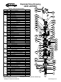
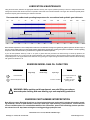
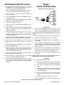
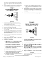
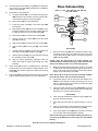
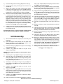
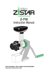
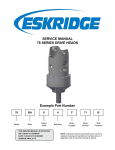
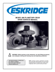
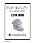
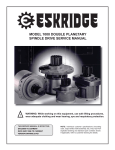
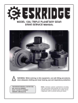
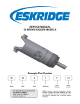
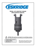
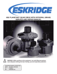
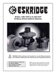
Service Manual 440 Series Digger models Example Part Number 440 81 4 4 f 95 D 9 Model Ratio Shaft Bail Boss Motor Supplier Motor Number Cover Input This service manual is effective: S/N: 70000 to current date: 5-2006 to CURRENT version:Smd44081-44f95d9 NOTE: Individual customer specifications (spindle mounting, sprocket pilot, brake assembly, etc.) may vary from exploded drawing and standard part numbers shown. If applicable, refer to customer drawing for details. Eskridge Exploded View Drawing 44081-44F95D9 13A MODEL 44081-44F95D9 DIGGER ITEM 1 2 3 4 5 5A 5B 5C 5D 5E 5F 5G 6 6A 6B 7 7A 7B 7C 7D 7E 7F 7G 8 8A 8B 8C 9 9A 9B 9C 9D 9E 9F 9G 10 10A 10B 10C 10D 10E 11 11A 11B 11C 12 12A 12B 12C 12D 13 13A 13B 13C 13D 13E 14 14A 14B 14C 15 15A 15B 15C 15D 15E 15F 15G 15H 16 QTY 1 1 1 1 (1) 1 3 3 36 6 9 3 DESCRIPTION BASE-"F" FLANGLESS OUTPUT SHAFT-4" SQUARE COVER (4 BOLT "D') INPUT GEAR CARRIER ASSEMBLY- STAGE 1 CARRIER PLANET GEAR PLANET SHAFT PLANET ROLLER THRUST WASHER ROLLER SPACER WASHER ROLL PIN SUN GEARS 1 SUN GEAR (STAGE 2) 1 SUN GEAR (STAGE 3) (1) CARRIER ASSEMBLY- STAGE 2 1 CARRIER 3 PLANET GEAR 3 PLANET SHAFT 60 PLANET ROLLER 6 THRUST WASHER 6 ROLLER SPACER WASHER 3 ROLL PIN RING GEARS 1 RING GEAR (STAGE 1) 1 RING GEAR (STAGE 2) 1 RING GEAR (STAGE 3) (1) CARRIER ASSEMBLY- STAGE 3 1 CARRIER 3 PLANET GEAR 3 PLANET SHAFT 120 PLANET ROLLER 6 THRUST WASHER 9 ROLLER SPACER WASHER 3 ROLL PIN THRUST WASHERS & BEARINGS 1 THRUST SPACER 2 THRUST WASHER 1 THRUST BEARING 1 CARRIER THRUST WASHER-STAGE 1 1 CASE THRUST WASHER-STAGE 1 SEALS & O-RINGS 2 O-RING - STAGE 1 3 O-RING - STAGES 2 & 3 1 OUTPUT SHAFT SEAL OUTPUT SHAFT BEARINGS 1 OUTER CONE 1 OUTER CUP 1 INNER CONE 1 INNER CUP HARDWARE 20 HEX CAP SCREW - 5/8-11 UNC - 9.5 20 HEX CAP SCREW - 5/8-11 UNC - 4.0 40 5/8 HELICAL SPRING LOCK WASHER 4 HEX CAP SCREW 3/4-10 UNC - 1.75 4 3/4 HELICAL SPRING LOCK WASHER PLUGS/ZERK 1 HOLLOW HEX PLUG -12 SAE 3 PIPE PLUG (3/4 NPT MAGNETIC) 1 PIPE PLUG (1/4 NPT) MISCELLANEOUS 1 STAGE 1 RING ADAPTER 1 BAIL ASSEMBLY * SHIM 1 LOCK RING 1 SPLIT RING (L-SEGMENT-425) 1 SUN GEAR RETAINGING RING - STAGE 2 1 SUN GEAR RETAINGING RING - STAGE 3 1 CARRIER RETAINING RING - STAGE 3 1 MOTOR X44081-44F95D9ab 03-22-10 HWP Eskridge, Inc. Olathe, KS. 913-782-1238 PART NO. 42-004-3022 42-004-4102 25-004-1232 25-004-1762 25-005-2201 25-004-1692 25-004-1712 25-004-1442 01-106-0010 13-004-1582 13-004-1592 01-153-0020 42-004-1512 42-004-1472 42-005-0101 42-004-1062 42-004-1102 42-004-1342 01-106-0040 42-004-1362 42-004-1352 01-153-0220 25-004-1562 42-004-1042 42-004-1032 42-005-0131 42-004-1402 42-004-1092 42-004-1332 01-106-0040 42-004-1362 42-004-1352 01-153-0220 13C 15B 13D 14A 13C 10B 10E 3 10D 5E 10C 4 11A 5F 5A 5C 5G 8A 5D 15A 15F 5B 7E 6A 7F 7A 8B 7C 11B 9E 15H 9G 9B 8C 15D 01-208-0030 01-207-0100 01-207-0020 14B 9D 15E 15C 7D 9C 9A 01-150-1950 01-150-1880 01-166-0040 01-150-1890 01-166-0360 7G 7B 15G 6B 01-102-0290 01-103-0290 01-102-0280 01-103-0280 42-004-2072 42-005-0171 42-004-1202 42-004-1212 42-004-1222 01-160-0740 01-160-0690 01-160-0680 01-304-0950 13B 10A 25-004-1842 01-112-0510 01-112-0500 25-004-1132 25-004-1752 01-402-0020 01-402-0840 01-405-0770 16 13E 9F 12C 12D 1 14C 11C 12B 12A 2 Model D440 service manual, SM 44081-44F95D9 Page www.eskridgeinc.com Lubrication & Maintenance Using the chart below, determine an appropriate lubricant viscosity. Use only EP (extreme pressure) or API GL-5 designated lubricants. Change the lubricant after the first 50 hours of operation and at 500 hour intervals thereafter. The auger drive should be partially disassembled to inspect gears and bearings at 1000 hour intervals. Recommended ambient and operating temperatures for conventional and synthetic gear lubricants -50 -25 0 25 50 75 100 125 150 175 200 225 250 F 107 121 C 80W90 conventional 75W90 conventional 85W140 conventional Min Ambient/operating temp Max Operating temp Max Ambient temp 75W90 synthetic 80W140 synthetic -45 -32 -18 -4 10 24 38 52 66 79 93 Note: Ambient temperature is the air temperature measured in the immediate vicinity of the gearbox. A gearbox exposed to the direct rays of the sun or other radiant heat sources will operate at higher temperatures and therefore must be given special consideration. The max operating temp must not be exceeded under any circumstances, regardless of ambient temperature. If your unit was specified “shaft up” or with a “-Z” option, a grease zerk was provided in the base housing. For shaft-up operation, the output bearing will not run in oil and must be grease lubricated. Use a lithium based or general purpose bearing grease sparingly every 50 operating hours or at regular maintenance intervals. Over-greasing the output bearing should be avoided as it tends to fill the housing with grease and thicken the oil ESKRIDGE MODEL D440 OIL CAPACITIES Operating Position Oil Capacity Single stage Horizontal Shaft - Vertical Shaft (Pinion Down) ! Double stage Oil Level Triple stage - To horizontal centerline of auger drive 4.4 GAL/ 16.8 liters To midway on upper/ primary gear set WARNING: While working on this equipment, use safe lifting procedures, wear adequate clothing and wear hearing, eye and respiratory protection. ESKRIDGE PART NUMBER INTERPRETATION Note: All non custom Eskridge Geardrives are issued a descriptive part number which includes information regarding the Model, means of shaft retention, base style, shaft style, input mounting, input shaft size, overall ratio and various available options. For a detailed breakdown of this information, please refer to Eskridge product specification sheets found at: http://www.eskridgeinc.com/diggers/diggerprodspecs.html Model D440 service manual, SM 44081-44F95D9 Page Eskridge, Inc. Olathe, KS. 913-782-1238 www.eskridgeinc.com Unit Disassembly Procedure 1) Stage I Carrier Subassembly Scribe a diagonal line across the outside of the unit from the bail (15B) to the base (1) before disassembly to aid in the proper positioning of pieces during reassembly. (Items 5A, 5B, 5C, 5D, 5E, 5F & 5G) 2) Remove magnetic drain plugs (14B) and drain oil from unit. The oil will drain out faster and more completely if warm. 5E 3) Remove the twenty hex-head capscrews (13A) and lockwashers (13C). 5F 4) Separate bail (15B) from ring gear adapter (15A) and remove from digger assembly. 5) Install two hex-head capscrews (13A) into ring gear adaptor (15A) to retain gearbox assembly together. 6) Remove motor (16) from cover (3). 7) Remove the twenty hex-head capscrews (13B) and lock washers (13C). 8) Remove cover (3), thrust bearings (10A, 10B, 10C, 10D & 10E), remove input gear (4). Inspect o-ring (11A); discard if damaged or deformed. 1) Remove retaining ring (15F) from stage II sun gear. Lift Stage I planet carrier assembly out of the unit (5). Remove ring gear (8A) and inspect o-ring (11A); discard if damaged or deformed. NOTE: Support only the carrier (5A) while pressing out planet shafts. 9) 5C 5G 5A 5D 5B Disassembly Rotate planet gears (5B) to check for abnormal noise or roughness in bearings (5D) or planet shafts (5C). If further inspection or replacement is required, proceed as follows. 2) Drive roll pins (5G) completely into the planet shafts (5C). 3) Press or drive planet shafts (5C) out of carrier (5A). 4) Remove planet gears (5B) and thrust washers (5E) from the carrier (5A). 5) Inspect the planet gear (5B), bearing bore, planet shaft (5C) and rollers (5D). Check for spalling, bruising or other damage. Replace components as necessary; rollers should be replaced only as a set of 12.. 6) Check primary planet shafts (5C) for any abnormal wear, especially ones where bearings needed to be replaced. If any abnormal wear is found, replace planet shafts. 14) With a suitable lifting apparatus and a hoist, lift the Stage III planetary assembly out of the unit (9). 7) Use 3/16 inch pin punch to remove roll pins (5G) from planet shafts (5C). 15) Remove Stage III ring gear (8C). Inspect o-ring (11B); as before, discard if damaged or deformed. NOTE: If either the rollers or the planet shafts (pins) are damaged, both components should be replaced. 16) The unit is now separated into subassemblies. The area(s) requiring repair should be identified by thorough inspection of the individual components after they have been cleaned and dried. Reassembly 10) Remove two hex-head capscrews (13A) and ring gear adapter (15A). Inspect o-ring (11B) as before; discard if damaged. 11) Remove retaining ring (15G) from stage III sun gear. Lift the Stage II planet carrier assembly out of the unit (7). 12) Remove the Stage II ring gear (8B). Inspect o-ring (11B); as before, discard if damaged. 13) Using a screwdriver, seal pick or similar tool remove the retaining ring (15H), which retains the Stage III planet carrier to the output shaft. The retaining ring can be left in the carrier but must be removed from the groove. 1) 2) To install rollers in planet gear bore: a) Set planet washer (5E) on work table, insert planet shaft in washer then slide one spacer (5F) over shaft (5C). b) Place planet gear (5B) centered over planet shaft (5C). c) Install tweleve rollers into planet gear bore. Slide two spacers (5E) onto planet shaft, slide planet washer (5F) onto planet shaft (5C). d) Carefully remove planet shaft from this assembly and move the gear with bearings and washers to the carrier. e) Slide the gear into place. (Oriented as shown.) Planet shafts (5C) should be installed with chamfered end of Model D440 service manual, SM4408144F95D9Page Eskridge, Inc. Olathe, KS. 913-782-1238 www.eskridgeinc.com 3/16 inch hole toward outside diameter of the carrier (5A). This will aid in alignment of holes while inserting roll pins (5G). 3) Drive a roll pin (5G) through the carrier hole and into the planet shaft to retain the parts. Repeat for other planet gears. Stage II Carrier Subassembly h) 3) Planet shafts (7C) should be installed with the chamfered end of the 3/16 inch hole towards the outside diameter of the carrier (7A); this will aid in alignment of holes while inserting roll pins (7G). 4) Drive roll pin (7G) into the carrier hole and into the planet shaft to retain the parts. Repeat for remaining planet gears. (Items 7A, 7B, 7C, 7D, 7E, 7F, & 7G) 7E 7F 7A Align the planet gear/bearing assembly inside the carrier and install the planet shaft through the entire assembly. 7C 7G 7B 7D Disassembly 1) Rotate planet gears (7B) to check for abnormal noise or roughness in bearings (7D). If further inspection or replacement is required, proceed as follows. 2) Drive roll pins (7G) completely into the planet shafts (7C). 3) Slide planet shafts (7C) out of carrier (7A). 4) Remove planet gears (7B), washers (7E) and rollers (7D) from carrier (7A). 5) 6) Stage III Carrier Subassembly (Items 9A, 9B, 9C, 9D, 9E, 9F, 9G & 15H) 9E 9C 15H Inspect the planet gear (7B), bearing bore, planet shaft (7C) and rollers (7D). Check for spalling, bruising or other damage. Replace components as necessary; rollers should be replaced only as a set of 20. 9G 9A 9B 9D Remove roll pins (7G) from primary planet shafts (7C) using a 3/16 inch pin punch. 9F Reassembly 1) Rebuild primary planet carrier assembly in reverse order using any needed new parts. 2) Install rollers in gear as follows: Disassembly 1) Set planet washer (7E) on work table with planet gear (7B) positioned on top of washer. Center the planet washer to the planet gear as closely as possible. Rotate planet gears (9B) to check for abnormal noise or roughness in bearings (9D). If further inspection or replacement is required, proceed as follows. 2) Drive roll pins (9G) completely into the planet shafts (9C). b) Center the planet shaft (7C) in the planet gear (7B) bearing bore. Install roller spacer (7F) onto planet shaft. 3) Slide planet shafts (9C) out of carrier (9A). 4) c) Begin placing rollers (7D) around the shaft (7C). There should be clearance for the last roller to slide in. Be sure to install 20 rollers in each planet gear. Remove planet gears (9B), washers (9E), spacers (9F) and rollers (9D) from carrier (9A). 5) d) Place spacer washer (7F) onto planet shaft. Inspect the planet gear (9B), bearing bore and planet shaft (9C) and rollers (9D). Check for spalling, bruising or other damage. Replace components as necessary; rollers should be replaced only as a set of 40 (2 rows of 20). e) Place a washer over the gear (7E) onto the shaft (7C). 6) f) Carefully slide the assembly off the table, holding the lower planet washer (7E) and planet gear (7B). Remove roll pins (9G) from secondary planet shafts (9C) using a 3/16 inch pin punch. a) g) Slide the planet shaft (7C) out of the assembly and slide the assembly into the carrier. Reassembly 1) Rebuild Stage III planet carrier assembly in reverse order using any needed new parts. Model D440 service manual, SM4408144F95D9Page Eskridge, Inc. Olathe, KS. 913-782-1238 www.eskridgeinc.com 2) 3) Base Subassembly Place the spiral-wound retaining ring (15H) in the depression at the center of the carrier (9A) in preparation for installation onto the output shaft (2). (Items 1, 2, 11C, 12A, 12B, 12C, 12D, 14B, 14C, 15C, 15D, & 15E) Install rollers in gear as follows: a) Set planet washer (9E) on work table with planet gear (9B) centered on top of washer. Center the planet washer and the planet gear as closely as possible. b) Slide a spacer (9F) over the planet shaft. c) Center the planet shaft (9C) in the planet gear (9B) bearing bore. d) Begin placing rollers (9D) around the shaft (9C). There should be clearance for the last roller to slide in. Be sure to install 20 rollers per row in the planet gear (9D). 15D 15E 15C 12C 12D 14B 1 14C 12B 12A 11C e) Slide a spacer (9F) over the first row of rollers (9D). f) Place a second row of rollers (9D) around the planet shaft (9C) as before. g) Slide a spacer (9F) over the second row of rollers (9D). h) Place a washer (9E) over the gear (9B) onto the shaft (9C). i) Carefully slide the assembly off the table, holding the lower planet washer (9E) and planet gear (9B). j) Slide the planet shaft (9C) out of the assembly and slide the assembly into the carrier (9A). Remove the lock ring (15D) using a heel bar or puller; if using a heel bar, be sure not to pry against the cage of the inner output shaft bearing (12C). Remove the split ring segments (15E) and shims (15C). k) Align the planet gear/bearing assembly inside the carrier and install the planet shaft through the entire assembly. Caution: Since the output shaft is no longer retained, care should be taken to avoid personal injury. Care should also be taken not to damage it when it is pressed through base. 2 Disassembly 1) 4) Planet shafts (9C) should be installed with the chamfered end of the 3/16 inch hole towards the outside diameter of the carrier (9C). This will aid in alignment of holes while inserting roll pins (9G). 2) 5) Drive roll pin (9G) through the carrier hole and into the planet shaft to retain the parts. Repeat for the other planet gears. Note: Removing the shaft from the base assembly damages the shaft seal and the seal will need to be replaced. Base (1) should be set pinion side down, as shown, on a plate or table. Press output shaft through the bottom of base by applying a load to top end (internal end) of shaft until it passes through inner shaft bearing cone (12C). 3) A gear puller may be used to remove the outer bearing cone (12A) from the shaft (2). If reusing old bearing cone, do not pull on or damage roller cage. Remove the shaft seal (11C) from the shaft for replacement. 4) Inspect inner and outer bearing cups (12B & 12D). If cups are damaged, drive them out using a brass drift and utilizing the bearing knock-out notches in the base (1) Reassembly 1) Clean all foreign material from magnetic oil plug (14C) located on the side of the base (1). 2) Place base (1) (output side up, opposite shown) on the table. 3) Apply a layer of lithium or general purpose bearing grease to the roller contact surface of outer bearing cup (12A). 4) Press outer bearing cone (12B) (large end down as shown) onto the shaft until it seats against the shoulder. Note: Press bearing cone onto output shaft by pressing on inner race only. DO NOT press on roller cage, as it may damage bearing. Model D440 service manual, SM4408144F95D9Page Eskridge, Inc. Olathe, KS. 913-782-1238 www.eskridgeinc.com 5) Place the shaft (2) with the bearing (12A) into the base (1). 6) Flip this assembly, resting the base (1) on the end of the output shaft (2). 7) Apply a layer of lithium or general purpose bearing grease to the roller contact surface of the inner cup (12D). Press the inner bearing cone (12C) (large end up as shown) onto the shaft (2) until it is seated against inner bearing cup (12D). 8) 9) Without the shaft seal (11C) installed, the preload may result in a rolling torque that varies between 50 to 300 in-lb. The bearing preload should be tailored to your application; a lowspeed application may require a high pre-load, high-speed applications usually benefit from low pre-load. Adding shims (15C) will increase the pre-load on the bearing set. Determine your pre-load requirement and install shims to obtain this pre-load. Install the Load-N-Lock™ segments (15E) over the shims (15C) and into the groove in the shaft (2). Finally, install the lock ring (15D) over the segments (15E). Lubricate inner lip of new shaft seal (11C) and slide it onto the shaft (2) and over the shaft seal diameter then press the seal into the base bore (1). All subassembly service or repairs should be complete at this time. Continue to Unit Assembly to complete unit buildup. Unit Assembly 1) When all subassemblies are complete, the unit is ready to be assembled. 2) Install the Stage III carrier assembly onto the output shaft; align the splines of the carrier (9A) with the splines of the shaft (2) and slide the carrier onto the shaft. 3) Install the retaining ring (15H) onto the groove of the shaft (2), using a spiraling motion. 4) Lubricate o-ring (11B) and install on the pilot of the Stage III ring gear (8C). Stage I gear adapter (15A) and temporally install two fasteners (13A) to hold assembly together. 11) Install the Stage II input gear (6A) and Stage I carrier assembly (5) onto the Stage II input gear. Place retaining ring (15F) onto sun gear groove using a spiraling motion. 12) Align gear teeth of ring gear (8A) with the gear teeth of the planet gears (5B) and place on ring adaptor. Align mounting holes of ring gear with holes in base. Using the scribed line made during disassembly for reference. 13) Install the input gear (4) then thrust bearings in the following order onto the input gear: carrier thrust washer (10D), case thrust washer (10E), one thrust washer (10B), thrust bearing (10C), one thrust washer (10B), and thrust spacer (10A). 15) Lubricate o-ring (11A) and install on the pilot of the cover (3). 16) Noting the scribed line made during disassembly, install the cover (3). 17) Install and torque the 20 5/8-11 hex-head cap-screws (13B) with lockwashers (13C). The torque for the cap-screws: 220 ft-lb dry, 170 ft-lb if the fasteners are lubricated. 18) Ensure the unit spins freely by using a splined shaft to drive the input gear (4). 19) Install motor (16) onto cover (3B) and align motor shifting mechanism with bail relief hole. Install motor fasteners. 20) Remove two temporally fasteners installed in step 10. Place bail (15B) onto assembly and aligning holes in bail and cover using scribed line made during disassembly as a reference. Install and torque the 20 5/8-11 hex head capscrews (13A) with lockwashers (13C). The torque for the capscrews is 220 ft-lbs dry, 170 ft-lbs if fasteners are lubricated. 21) Fill the unit to the proper level, as specified, with GL5 EP 80/90 gear oil after it is sealed with a brake and/or motor. The digger is now ready to use. Caution: Hold ring gear by outside or use lifting device to prevent injury. 5) Install Stage III sun gear (6B) into Stage III carrier assembly. 6) Align gear teeth of ring gear (8C) with the gear teeth of the planet gears (9B) and place on base. Align mounting holes of ring gear with holes in base. Using the scribed line made during disassembly for reference. 7) Slide Stage II carrier (7A) onto Stage III sun gear (6B) then install retaining ring (15G) onto sun gear groove using a spiraling motion. 8) Lubricate o-ring (11B) and install on the pilot of the Stage II ring gear (8B). 9) Align gear teeth of ring gear (8B) with those of the planet gears and place on Stage III ring gear. Align mounting holes of ring gear with holes in base. Use the scribed line made during disassembly for reference. 9) Lubricate o-ring (11B) and install on the pilot of the Stage I ring gear adaptor (15A). 10) Noting the scribed line made during disassembly, install the Model D440 service manual, SM4408144F95D9Page Eskridge, Inc. Olathe, KS. 913-782-1238 www.eskridgeinc.com