1
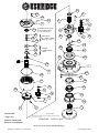
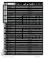
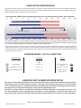
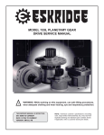
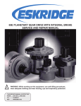
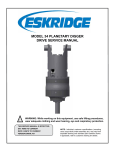
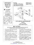
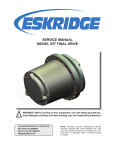
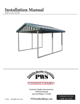
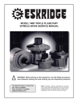
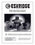
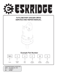
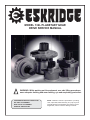
MODEL 132L PLANETARY GEAR
DRIVE SERVICE MANUAL
!
WARNING: While working on this equipment, use safe lifting procedures,
wear adequate clothing and wear hearing, eye and respiratory protection.
THIS SERVICE MANUAL IS EFFECTIVE:
S/N: 48501 TO CURRENT
DATE: 8/31/00 TO CURRENT
VERSION: SM132LD2-AD
NOTE: Individual customer specifications (mounting
case, output shaft, brake assembly, etc.) may vary from
exploded drawing and standard part numbers shown.
If applicable, refer to customer drawing for details.
14A
5C
25A
25B
30A
5E
6
3
14C
}
14F
14E
14F
14C
35D
14D
5D
USED WITH ALL BUT:
36:1 CODE 4 INPUT
& ALL 33:1 & 45:1
}
USED WITH:
36:1 CODE 4 INPUT
& ALL 33:1 & 45:1
}
5B
5A
35C
5E
5F
35B
35A
SINGLE
PLANETARIES
ONLY
16B
20C
20D
30C
OR
14B
1
4
25D
16B
25C
20B
12
7E
30B
20A
7D
7B
16A
7E
7F
7A
X132LD2-AE,
16C
2
7C
E.C.N. 2790
EFFECTIVE DATE 08/31/00
EFFECTIVE SERIAL # 48502
R
Page 1 of 2
Effective date 8/31/00
EQUIPPED WITH PATENTED "LOAD-N-LOCK"
(U.S. PATENT NO. 5746517).
X132LD2-AE
SHAFT RETENTION SYSTEM.
DATE 11-19-07
Effective serial # 48502
Model 132L service manual, SM132LD2-AD Page 1
Eskridge, Inc. Olathe, Ks. 913-782-1238
www.eskridgeinc.com
SINGLE PLANETARY
X132LD2-AD,
Page 2 of 2
Effective date 8/31/00
Effective serial # 48502
INPUT GEAR
COVER
OUTPUT SHAFT
BASE
MODEL 132L
RATIOS
ITEM QTY DESCRIPTION
A - ROUND FLANGE
A - ROUND FLANGE W/BOOT SEAT
1
1 B - SQUARE FLANGE
E - RECTANGULAR
F - FLANGELESS
AQ - ECCENTRIC, ROUND FLANGE
C - CUSTOM
D1 23 T 8/16 DP SPL 2.25" LG
D2 3.000" DIA, 5/8" SQ KEY
D3 23 T 8/16 DP SPL 1.22" LG
2
1
D4 23 T 8/16 DP SPL 2.72" LG
D5 3.500" DIA, 7/8" SQ KEY
D6 20T 6/12 DP SPL 4.15" LG
S1 SPINDLE SHAFT
C1 CUSTOM
SAE 'A' 2 & MOD. 4 BOLT
SAE 'A' 2 & MOD. 4 BOLT W/ CODE 4
SAE 'B' 2 BOLT
3
1
SAE 'B' 2 & 4 BOLT W/ CODE 4
SAE 'C' 2 BOLT & 4 BOLT
SAE 'D' 4 BOLT W/ CODE 9 * *
CODE 2 - INPUT 13 T 16/32 DP
CODE 3 - INPUT SAE 1"-6B
4
1 CODE 4 - INPUT 14 T 12/24 DP
CODE 5 - INPUT 15 T 16/32 DP
CODE 9 - INPUT 13 T 8/16 DP * *
(1) CARRIER ASSEMBLY-SECONDARY
5
5A 1
CARRIER (SEC)
5B 3
PLANET GEAR (SEC)
5C 3
PLANET SHAFT (SEC)
5D 6
BRG - SEC. PL.
5E 6
THRUST WASHER - PLANET
5F 3
ROLL PIN - SEC. PL. 3/16 X 7/8
SUN GEAR
6
1
(1) CARRIER ASSEMBLY-PRIMARY
7
7A 1
CARRIER (PRI)
7B 3
PLANET GEAR (PRI)
7C 3
PLANET SHAFT (PRI)
7D 3
BRG - PRI. PL.
7E 6
THRUST WASHER - PLANET
7F 3
ROLL PIN - PRI. PL. 1/8 X 7/8
12 1 RING GEAR
-- THRUST WASHERS & THRUST BRGS
14
14A 1 CARRIER THRUST WASHER
14B 1 CARRIER THRUST WASHER
14C 1 INPUT THRUST WASHER
14D 1 THRUST WASHER SGL PL
14E 1 BEARING
14F 2 THRUST RACE
(1) SEAL KIT
16
16A 1 SHAFT SEAL
16B 2 O-RING
16C 1 SEAL - RUBBER (DIRT BOOT)
--- OUTPUT SHAFT BEARINGS
20
OUTER CONE
20A 1
OUTER CUP
20B 1
INNER CONE
20C 1
INNER CUP
20D 1
--- HARDWARE
25
25A 8
BOLTS - COVER
25B 8
LOCKWASHERS - COVER
25C 16 BOLTS - RING
25D 16 HARD WASHERS - RING
--- PLUGS /GREASE ZERK
30
PLUG - COVER
30A 1
PLUG - RING
30B 2
1/4 NPT (SOC. HD.)
30C 1
GREASE FITTING
35
MISCELLANEOUS
35A
SHIMS
35B 1
SPLIT RING
35C 1
LOCK RING
35D 1 RETAINING RING
*
**
4:1
6:1
4.42
6.00
DOUBLE PLANETARY
19.54:1
4.42
4.42
26.52:1
4.42
6.00
33.00:1
7.50
4.42
13-004-3102
13-004-3042
13-004-3082
13-004-3052
13-004-3152
13-004-3112
36.00:1
36.00:1
6.00
6.00
6.00
6.00
W/CODE 4 W/O CODE 4
45.00:1
7.50
6.00
13-004-4352M
13-004-4312M
13-004-4362M
13-004-4372M
13-004-4382M
13-004-4342M
13-004-4202M
-----------------
13-004-1252
-----------------
13-004-1202
13-004-1212
13-004-1412
---------------------------------
13-004-1372 13-004-1382
-----------------
13-004-1192
13-004-1252
13-004-1182
13-004-1202
13-004-1212
13-004-1192
13-004-1252
13-004-1182
13-004-1202
13-004-1212
13-004-1292
13-004-1322
13-004-1342
13-004-1452
13-004-1292
13-004-1322
13-004-1342
13-004-1452
13-004-1222
13-004-1192 13-004-1222
13-004-1222 13-004-1222
13-004-1222
13-004-1232
13-004-1182 13-004-1232
13-004-1232 13-004-1232
13-004-1232
13-004-1242 13-004-1242 13-004-1212 13-004-1242
-----------------
13-004-1312
13-004-1302
13-004-1472
13-004-1332
13-004-1362 13-004-1352
13-004-1802
13-004-1442
13-004-1402
13-005-2001
13-004-1062
13-004-1082
----------------13-004-1462
13-005-2011 13-005-2001 13-005-2011 13-005-2001
13-004-1072 13-004-1062 13-004-1072 13-004-1062
13-004-1092 13-004-1082 13-004-1092 13-004-1082
81-004-0061
01-105-0500
81-004-1561
01-153-0210
----------------13-004-1142 13-004-1152 13-004-1142
----------------13-005-2021 13-005-2021 13-005-2041
----------------13-004-1032 13-004-1032 13-004-1052
----------------13-004-1102 13-004-1102 13-004-1122
----------------13-004-1021
----------------01-105-0590
----------------81-004-1561
----------------01-153-0180
81-004-2362
13-004-1312
13-004-1472
13-004-1362
13-004-1802
13-005-2011 13-005-2011 13-005-2011
13-004-1072 13-004-1072 13-004-1072
13-004-1092 13-004-1092 13-004-1092
13-004-1152
13--005-2031
13--004-1042
13-004-1112
13-004-1152
13-005-2031
13-004-1042
13-004-1112
13-004-1152
13-005-2041
13-004-1052
13-004-1122
----------------
81-004-2711
81-004-2711 81-004-2711 ---------------- 81-004-2711
---------------81-004-2701 81-004-2701
81-004-2701 ----------------
----------------
81-004-2711
81-004-2883
01-112-0030
-----------------
----------------
----------------
----------------
----------------
----------------
01-112-0220 01-112-0220
01-112-0230 01-112-0230
-------------------------------
01-112-0220
01-112-0230
13-016-2051 Contains Items 16A, 16B and 16C: 13-016-2101 SEAL KIT contains only items 16A and 16B
01-405-0690
01-402-0420
01-406-0050 DIRT BOOT IS USED ON THE S1 SPINDLE SHAFT WITH A 13-004-3042 OR 13-004-3052 BASE.
----------------
01-102-0260
01-103-0260
01-102-0030
01-103-0030
----------------
01-150-1670
01-166-0010
(FOR 13-004-1402 COVER, USE 01-150-1710 SHCS)
(FOR 13-004-1402 COVER, DO NOT USE LOCKWASHERS)
01-150-1460
01-166-0120
----------------
01-207-0070
01-207-0041
01-207-0020
01-215-0040
-----------------
80-004-1151 (
*
QUANTITY DETERMINED BY PRELOAD REQUIRED AND PART STACK-UP)
81-004-8101
81-004-8111
01-160-0040
-----------------
SAE "D" COVER IS SOLD ONLY WITH A CODE 9, 13 T- 8/16 INPUT GEAR.
Eskridge, Inc. Olathe, Ks. 913-782-1238
Model 132L service manual, SM132LD2-AD Page 2
www.eskridgeinc.com
LUBRICATION & MAINTENANCE
Using the chart below, determine an appropriate lubricant viscosity. Use only EP (extreme pressure) or API GL-5 designated lubricants.
Change the lubricant after the first 50 hours of operation and at 500 hour intervals thereafter. The gear drive should be partially disassembled to inspect gears and bearings at 1000 hour intervals.
Recommended ambient and operating temperatures for conventional and synthetic gear lubricants
-50
-25
0
25
50
75
100
125
150
175
200
225
250 F
107
121 C
80W90 conventional
75W90 conventional
85W140 conventional
Min Ambient/operating temp
Max Operating temp
Max Ambient temp
75W90 synthetic
80W140 synthetic
-45
-32
-18
-4
10
24
38
52
66
79
93
Note: Ambient temperature is the air temperature measured in the immediate vicintiy of the gearbox. A Gearbox exposed to the direct rays of
the sun or other radiant heat sources will operate at higher temperatures and therefore must be given special consideration. The max operating
temp must not be exceeded under any circumstances, regardless of ambient temperature.
If your unit was specified “shaft up” or with a “-Z” option, a grease zerk was provided in the base housing. For shaft-up operation, the
output bearing will not run in oil and must be grease lubricated. Use a lithium based or general purpose bearing grease sparingly every
50 operating hours or at regular maintenance intervals. Over-greasing the output bearing should be avoided as it tends to fill the housing
with grease and thicken the oil
ESKRIDGE MODEL 132L OIL CAPACITIES
Operating Position
Oil Capacity
Oil Level
Single/Double
stage
Horizontal Shaft
3.0 pints / 1.4 l
To horizontal centerline of
gear drive
Vertical Shaft (Pinion Up)
5.0 pints / 2.4 l
To side port on ring gear
Vertical Shaft (Pinion Down)
5.0 pints / 2.4 l
To midway on upper/
primary gear set
ESKRIDGE PART NUMBER INTERPRETATION
Note: All non custom Eskridge Geardrives are issued a descriptive part number which includes information regarding the Model, means of shaft retention, base style, shaft style, input mounting, input shaft size, overall ratio and
various available options. For a detailed breakdown of this information, please refer to Eskridge product specification sheets found at: http://www.eskridgeinc.com/geardrives/gearprodspecs.html
The 132L is no longer sold for new applications and the part number description is not available on the web. Use
the 130L information to aid in interpreting the part number. For new applications, consider the 133L which has a
large shaft like the 132L and it has higher load-rated planet bearings which give a longer life in most applications.
Model 132L service manual, SM132LD2-AD Page 3
Eskridge, Inc. Olathe, Ks. 913-782-1238
www.eskridgeinc.com
Unit Teardown
1)
Scribe a diagonal line across the outside of the unit from the
cover (3) to the base (1) before disassembly to aid in the proper
positioning of pieces during reassembly.
2)
Remove drain plugs (30B) and drain oil from unit. The oil will
drain out more quickly and completely if warm.
3)
Remove
the
8
lockwashers (25B).
4)
Remove the cover (3), thrust washer(s)/bearing(s)
(14C or 14E & 14F OR 14B, 14C, 14D & 35D), and input gear (4). Inspect o-ring (16B); discard if damaged or
deformed.
3/8-16
cap-screws
(25A)
and
5)
Lift the planet carrier assembly out of the unit .
6)
Remove secondary carrier assemblie. Remove ring gear (12),
if necessary by removing the 16 1/2-13 12-point cap-screws
(25C & 25D). Inspect the gear to base O-ring (16B); as before,
discard if damaged or deformed.
7)
The unit is now disassembled into groups of parts.
The area(s) requiring repair should be identified by thorough
inspection of the individual components after they have been
cleaned and dried.
Carrier Assembly Teardown
Rotate planet gears (7B pri/5B sec) to check for abnormal
noise or roughness in bearings (7D pri/5D sec). If further inspection or replacement is required, proceed as follows.
Base Subassembly Teardown
1)
Remove the lock ring (35C) using a heel bar or puller; if
using a heel bar, be sure not to pry against the cage of
the inner output shaft bearing (20C). Remove the split ring
segments (35B) and shims (35A).
Caution: Since the shaft is no longer positively retained,
care should be taken to avoid personal injury. Care should
also be taken not to damage it while pressing through
base.
Note: Removing the shaft from the base assembly damages
the shaft seal and the seal will need to be replaced.
2)
Place base (1) external side down, on a plate or table.
Press output shaft out bottom of base by applying a load
to internal end of shaft until it passes through inner shaft
bearing cone (20C).
3)
A gear puller may be used to remove the outer bearing
cone (20A) from the shaft (2). If reusing old bearing cone,
do not pull on or damage roller cage. Remove the shaft
seal (16A) for replacement.
4)
Lubricate inner lip of new shaft seal (16A) and slide it onto
the shaft (2) until it fits snugly over the shaft seal diameter
with the open side toward the inside of the gear drive.
Note: Press bearing cone onto output shaft by pressing
on inner race only. DO NOT press on roller cage, as it may
damage bearing.
5)
Inspect inner and outer bearing cups (20D & 20B). If cups
are damaged, drive them out using a brass drift and utilizing the bearing knock-out notches in the base (1)
1)
Drive roll pins (7F pri/5F sec) completely into the planet shafts
(7C pri/5C sec).
2)
Slide planet shafts (7C pri/5C sec) out of carrier (7A pri/5A
sec).
1)
Remove planet gears (7B pri/5B sec), washers (7E pri/5E sec)
and bearings (7D pri/5D sec) from carrier (7A pri/5A sec).
Clean all foreign material from any magnetic oil plugs located on base (1).
2)
Place base (1) exterior side up on work table.
3)
4)
5)
Base Reassembly
Inspect the planet gear (7B pri/5B sec), bearing bore and planet shaft (7C pri/5C sec) and bearings (7D pri/5D sec). Check
for spalling, bruising or other damage and replace components
as necessary.
3)
Apply a layer of lithium or general purpose bearing grease
to the roller contact surface of outer bearing cup (20B).
4)
Press outer bearing cone (20A) onto the shaft until it seats
against the shoulder.
Remove roll pins (7F pri/5F sec) from planet shafts (7C pri/5C
sec) using a 1/16 pri/ 3/16 sec inch pin punch.
5)
Place the shaft (2) with the bearing (20A) into the base
(1).
6)
Flip shaft/base assembly, and apply lithium or
general purpose bearing grease to roller contact surface of the inner cup (20D)., then press
inner bearing cone (20C) onto shaft (2) until it seats against
inner bearing cup (20D).
7)
Prior to installation of the shaft seal (16A), the preload may result in a rolling torque which varies between 50 to 350 in-lb. The bearing preload should be
tailored to your application; a low-speed application may
require a high pre-load, while high-speed applications
usually benefit from low pre-load. Adding shims (35A) will
increase the pre-load on the bearing set. Determine your
pre-load requirement and install shims to obtain this pre-
Carrier Reassembly
1)
Insert the bearings (7D pri/5D sec) into the planet gears (7B
pri/5B sec). Place a planet washer (7E pri/5E sec) on top and
bottom of planet gear and slide into carrier (7A pri/5A sec).
2)
Planet shafts (7C pri/5C sec) should be installed with chamfered end of 1/16 pri/3/16 sec
inch
roll pin hole towards out-side diameter of
carrier (7A pri/5A sec); this will ease alignment of holes while
inserting roll pins (7F pri/5F sec).
3)
Drive roll pin (7F pri/5F sec) into the carrier hole and into planet shaft to retain parts. Repeat for remaining planet gears.
Model 132L service manual, SM132LD2-AD Page 4
Eskridge, Inc. Olathe, Ks. 913-782-1238
www.eskridgeinc.com
load.
Install the Load-N-Lock™ segments (35B) over the
shims (35A) and into the groove in the shaft (2). Finally, install
the lock ring (35C) over the segments (35B).
All subassembly service or repairs should be complete at this
time. Continue to Unit Assembly to complete unit buildup..
Unit Assembly
1)
Install the secondary carrier assembly (5) onto the output shaft;
align the splines of the carrier (5A) with the output shaft (2)
splines and slide the carrier onto the shaft.
2)
Lubricate o-ring(s) (16B) and install on the base (1) pilot and
cover (3) pilot.
Caution: Hold ring gear(s) by outside diameter or use lifting device to prevent injury.
3)
Align gear teeth of secondary ring gear (12) with the gear teeth
of the planet gears (5B) and place on base., then align mounting
holes of ring gear with holes in base. Use the scribed line made
during disassembly for reference.
4)
Install and torque the 16 1/2-13 12-point counter-sunk head
cap-screws (25C) with hard washers (25B). The torque for the
cap-screws: 110 ft-lb dry, 90 ft-lb if the fasteners are lubricated.
5)
Install the primary carrier assembly (7) and sun gear (6) into
the secondary carrier.
6)
Install the input gear (4).
7)
Install the thrust bearing set (Either 14C or 14E & 14F or 14B,
14C, 14D & 35D) Refer to exploded view for details.
8)
Noting the scribed line made during disassembly, (with lubricated o-ring in place) align and install the cover (3). Install the 8
3/8-16 hex-head cap-screws and lockwashers (25A and 25B).
Tighten to a torque of 45 ft-lb dry, 35 ft-lb if the fasteners are
lubricated.
9)
Using a splined shaft to drive the input gear (4) ensure that the
unit spins freely.
10)
Fill the unit to the proper level, as specified, with recommended
gear oil (refer to chart, page 3) after unit is sealed with brake
and/or motor.
The gearbox is now ready to use.
Model 132L service manual, SM132LD2-AD Page 5
Eskridge, Inc. Olathe, Ks. 913-782-1238
www.eskridgeinc.com