1
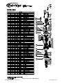
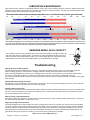
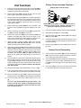
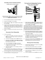
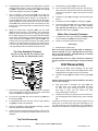
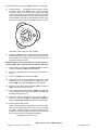
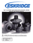
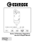
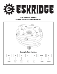
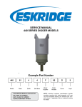
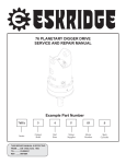
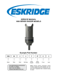
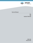
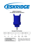
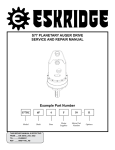
MODEL 34 PLANETARY DIGGER
DRIVE SERVICE MANUAL
!
WARNING: While working on this equipment, use safe lifting procedures,
wear adequate clothing and wear hearing, eye and respiratory protection.
THIS SERVICE MANUAL IS EFFECTIVE:
S/N: 46968 TO CURRENT
DATE: 6/28/10 TO CURRENT
VERSION:.SM34L-AA
NOTE: Individual customer specifications (mounting
case, output shaft, brake assembly, etc.) may vary from
exploded drawing and standard part numbers shown.
If applicable, refer to customer drawing for details.
25A
25G
40B
50
(40A)
25B
30C
25H
30B
40N
40L
40M
4
40H
45
40P
16C
14B
40G
40F
16D
40J
3
30A
12B
8C
8E
8D
40K
6B
25C
8F
8A
8B
8E
5C
7
14A
5A
6A
5E
5D
5F
5G
5D
16B
5B
5E
12A
40D
40E
20C
20D
30A
40C
16B
1
20B
20A
16A
(2)
Model 34 service manual, SM34L-AA Page 1
Eskridge, Inc. Olathe, Ks. 913-782-1238
www.eskridgeinc.com
LUBRICATION & MAINTENANCE
Using the chart below, determine an appropriate lubricant viscosity. Use only EP (extreme pressure) or API GL-5 designated lubricants.
Change the lubricant after the first 50 hours of operation and at 500 hour intervals thereafter. The gear drive should be partially disassembled to inspect gears and bearings at 1000 hour intervals.
Recommended ambient and operating temperatures for conventional and synthetic gear lubricants
-50
-25
0
25
50
75
100
125
150
175
200
225
250 F
107
121 C
80W90 conventional
75W90 conventional
85W140 conventional
Min Ambient/operating temp
Max Operating temp
Max Ambient temp
75W90 synthetic
80W140 synthetic
-45
-32
-18
-4
10
24
38
52
66
79
93
Note: Ambient temperature is the air temperature measured in the immediate vicinity of the gearbox. A Gearbox exposed to the direct rays of
the sun or other radiant heat sources will operate at higher temperatures and therefore must be given special consideration. The max operating
temp must not be exceeded under any circumstances, regardless of ambient temperature.
ESKRIDGE MODEL 34 OIL CAPACITY
The oil capacity of this unit is 9.75 pints/(4.6 liters). Proper oil level will measure to middle of primary ring
gear when auger drive is in vertical position. To check the oil in fully assembled units, fill the gear drive
with the proper oil (see information above) until it runs out of the fill plug while the auger drive is leaning
approximately 4.30 inches from vertical (approximately 7°); see the illustration to the right.
Troubleshooting
FILL PORT
4.30
Rattling, Grinding or Whining Noises
Hydraulic motor failure and/or difficulties are commonly confused with gear drive problems, as they can share similar symptoms:
reports of rattling, grinding or whining noises in the digger assembly. Carefully check the hydraulic motor for problems
before removing the digger drive from the boom. If the digger drive is removed, a motor problem can only be determined by testing
the motor on a hydraulic test stand or by eliminating the gear drive as the noise source after a total teardown of the unit.
If you determine that the hydraulic motor is the source of the problem, please contact the original equipment manufacturer of the digger
drive assembly.
Shifting Difficulties/Jumping Out of Gear
This symptom, commonly attributed to gear drive failure, can be due to air in the hydraulic lines leading to the drive, not the drive itself.
Excessive back-pressure in the system may also cause this problem.
Inability to Shift into High Gear
This symptom can be due to a poorly adjusted shift cylinder. While the cylinder is carefully set at the factory, the process of disassembly
may turn or move the cylinder in such a way that it contacts the case; contact between the cylinder body and the gear drive prevents
the rod from making its full one inch travel.
Difficult, Rough or Impossible Shifting
Hand testing a shifter may indicate a “no shift” condition even when the shifter is okay. If metal-to-metal contact is made, a short turn of
the output shaft may align shifter and allow shift to occur.
Diagnosing the Upper Gear Drive Area
The Series 34 digger drive cannot be shifted “on the fly.” The digger drive must be at a complete stop, with the load removed (backed
out of hole in ground), before shifting. Shifting on the fly is the primary cause of damage to the gears in the shifter assembly. Damage
caused by shifting on the fly will be seen as initial grinding of the gears at the gear faces, a wear pattern developing on the top of the
cluster gears and on the shift gear itself, and a severe wear pattern developing on the points of the shifter gear. Additionally, the sun
gear will show damage on the points: a rounding, or even severe burring, of these parts is possible.
Model 34 service manual, SM34L-AA Page 2
Eskridge, Inc. Olathe, Ks. 913-782-1238
www.eskridgeinc.com
Unit Teardown
1)
Primary Carrier Assembly Teardown
Items(8A, 8B, 8C, 8D, 8E and 8F)
Scribe a line across the outside of the unit from the bail (40B) to
the bearing carrier (1) before disassembly to aid in the proper
positioning of pieces during reassembly.
2)
Remove drain plugs (30A) and drain oil from unit. The oil will
drain out more quickly and completely if warm.
3)
Remove upper shift cylinder (40A) bolt. If shifter performance
is in doubt, leave lower bolt in place and follow cylinder adjustment procedure (Step 14 in Unit Assembly Procedure) to see
if poor cylinder adjustment could be the cause of “no-shift” or
“partial-shift” condition.
8C
8E
8D
8F
8A
8B
8E
Rotate planet gears (8B) to check for abnormal noise or
roughness in bearings (8D). If further inspection or replacement is required, proceed as follows.
4)
Remove lower shift cylinder (40A) bolt, nut and washer. The
bolt and nut are accessible through the clearance hole in the
bail.
5)
Remove the twenty 7/16-20 cap-screws (25A) and lockwashers (25G) and lift the bail (40B) from the unit.
1)
Drive roll pins (8F) completely into the planet shafts (8C).
2)
Slide planet shafts (8C) out of carrier (8A).
6)
Remove two cap-screws (25B) and lock washers (25H) from
hydraulic motor (50). Notice that the motor is larger on one
side: it must be replaced the same position as removed. Remove motor from unit. Check o-ring (16D) for damage.
3)
Remove planet gears (8B), washers (8E) and bearings
(8D) from carrier (8A).
4)
Inspect the planet gear, planet shaft and bearings. Check
for spalling, bruising or other damage and replace components as necessary.
5)
Remove roll pins (8F) from planet shafts using a 3/16 inch
pin punch.
7)
8)
9)
Observe location of shift fork (40L), shifter gear assembly
(Items 16C, 40F, 40G, 40H, 40J and 45) and top case (3).
Check for binding or loose shift connections.
Press down on shift lever (40F). Remove shifter gear assembly
(Items 4, 40M and 40N). If shifter is jammed and sun gear (4)
cannot be removed, dismantle shifter assembly in the case by
removing snap rings (40G). Pull shifter shaft out (45) of case.
Pull shifter collar assembly (40M), fork (40L) and shifter gear
(4) out of case. Shifter gear should be free of nicks, burrs or
gouges.
Use a screwdriver, wood chisel or similar flat strong tool ground
flat for insertion between the aluminum top case (3) and the
ring gear (12A). Tap lightly on tool: do not drive into case, heavy
prying will damage the o-ring contact surfaces in the case. Remove the top case assembly (Items 3, 6A, 6B, 12B, 14B, 25C,
30A, 40K and 40P).
10) Lift the primary planet carrier subassembly out of the unit (8).
Primary Carrier Reassembly
1)Press two bearing assemblies (8D) into each cluster gear
(8B). Place one washer on top and one washer on bottom
of the cluster gear and install into carrier.
2)
Planet shafts (8C) should be installed with chamfered end
of 3/16 inch roll pin hole towards outside diameter of carrier (8A); this will ease alignment of holes while inserting
roll pins.
3)
Drive roll pin (8F) into the carrier hole and into planet shaft
to retain parts. Repeat for remaining planet gears.
11) If sun gear (7) has not been removed from digger drive, do so
now. (Sometimes the sun gear sticks to the primary carrier (8)).
12) Remove secondary ring gear (12A). Inspect top-case to gear
and gear to base O-ring (16B); discard if damaged or deformed.
13) Lift the secondary planet carrier subassembly out of the unit
(5).
The unit is now disassembled into groups of parts. The
area(s) requiring repair should be identified by thorough
inspection of the individual components after they have
been cleaned and dried.
Model 34 service manual, SM34L-AA Page 3
Eskridge, Inc. Olathe, Ks. 913-782-1238
www.eskridgeinc.com
Secondary Carrier Assembly Teardown
Bearing Carrier Subassembly Teardown
Items(5A, 5B, 5C, 5D, 5E, 5F and 5G)
Items(1, 2, 16A, 16B, 20A, 20B, 20C,
20D, 30A, 40C, 40D and 40E)
5C
5A
5F
5E
40D
5D
40E
5G
20C
5D
20D
5B
30A
5E
40C
16B
1
20B
20A
16A
Rotate planet gears (5B) to check for abnormal noise or roughness in bearings (5D). If further inspection or replacement is
required, proceed as follows.
1)
Drive roll pins (5F) completely into the planet shafts (5C).
2)
Slide planet shafts (5C) out of carrier (5A).
3)
Remove planet gears (5B), washers (5E) and bearings (5D)
from carrier (5A).
4)
Inspect the planet gear, planet shaft and bearings. Check for
spalling, bruising or other damage and replace components as
necessary. Note: When using loose (uncaged individual) rollers, all rollers in the planet gear should be replaced if any are
found to be defective
5)
Remove roll pins (5F) from planet shafts using a 3/16 inch pin
punch.
(2)
1) Remove the lock ring (40D) using a heel bar or puller; if
using a heel bar, be sure not to pry against the cage of
the inner output shaft bearing (20C). Remove the split ring
segments (40E) and shims (40C).
Caution: Since the shaft is no longer positively retained,
care should be taken to avoid personal injury. Care should
also be taken not to damage it while pressing through base.
Note: Removing the shaft from the base assembly damages
the shaft seal and the seal will need to be replaced.
2)
Place bearing carrier (1) external side down, on a plate or
table. Press output shaft out bottom of base by applying a
load to internal end of shaft until it passes through inner
shaft bearing cone (20C).
3)
A gear puller may be used to remove the outer bearing
cone (20A) from the shaft (2). If reusing old bearing cone,
do not pull on or damage roller cage. Remove the shaft
seal (16A) for inspection or replacement.
4)
Inspect inner and outer bearing cups (20B & 20D). If cups
are damaged, drive them out using a brass drift and utilizing the bearing knock-out notches in the base (1)
Secondary Carrier Reassembly
1)
Loose roller installation:
a) Set planet washer (5E) on work table with planet gear
(5B) on top of it. Center planet washer to planet gear as
closely as possible.
2)
3)
b)
Center planet shaft (5C) in planet gear (5B) bearing bore.
c)
Begin placing rollers (5D) around shaft (5C). There should
be clearance for last roller to slide in. Install spacer (5G)
then install second row of rollers.
d)
Place a washer (5E) over gear (5B) and shaft (5C).
e)
Carefully slide assembly off of table, holding planet washers (5E) against planet gear (5B).
1)
Clean all foreign material from the magnetic oil plug (30A)
located on bearing carrier (1).
f)
Slide planet shaft (5C) out of the assembly and slide assembly into carrier.
2)
Place bearing carrier (1) exterior side up on work table.
3)
Apply a layer of lithium or general purpose bearing grease
to the roller contact surface of outer bearing cup (20B).
4)
Press outer bearing cone (20A) onto the shaft until it seats
against the shoulder.
5)
Place the shaft (2) with the bearing (20A) into the base (1).
Planet shafts (5C) should be installed with chamfered end of
3/16 inch roll pin hole towards outside diameter of carrier (5A);
this will ease alignment of holes while inserting roll pins (5F).
Drive roll pin (5F) into the carrier hole and into planet shaft to
retain parts. Repeat for remaining planet gears.
Bearing Carrier Reassembly
Model 34 service manual, SM34L-AA Page 4
Eskridge, Inc. Olathe, Ks. 913-782-1238
www.eskridgeinc.com
6)
7)
8)
Flip shaft/bearing carrier assembly, and apply lithium or general
purpose bearing grease to roller contact surface of the inner
cup (20D). Then press inner bearing cone (20C) onto shaft (2)
until it seats against inner bearing cup (20D).
Prior to installation of the shaft seal (16A), the preload may
result in a rolling torque which varies between 100 to 300 in-lb.
The bearing preload should be tailored to your application; a
low-speed application may require a high pre-load, while highspeed applications usually benefit from low pre-load. Adding
shims (40C) will increase the pre-load on the bearing set. Determine your pre-load requirement and install shims to obtain
this pre-load.
Install the Load-N-Lock™ segments (40E) over the shims
(40C) and into the groove in the shaft (2). The Load-N-Lock
segments should be oriented so the 15 degree angle matches
the 15 degree angle groove cut in the shaft and the small detent
on the OD of the segments is oriented towards the bearings.
Finally, install the lock ring (40D) over the segments (40E). The
Load-N-Lock lock ring must be oriented so the smaller outside
diameter is oriented towards the bearings; the detent groove
in the lock ring (which matches the detent bead in the Load-NLock segments) should be towards the bearings as well.
Top Case Assembly Teardown
Items(3, 4, 6A, 6B, 12B, 14B, 16C, 16D, 25C, 30A,
40F, 40H, 40J, 40K, 40L, 40M, 40N 40P and 45)
40N
40L
40M
4
40H
40F
45
1)
Install primary ring gear (12B) into top case (3).
2)
Prior to inserting socket-head cap-screws, coat the internal threads of the top case with Loctite 242 thread-locking
compound or equivalent. Tighten cap-screws to a torque
of 30 ft-lb.
3)
Install the sun gear (6A) and lightly coat the bushing with
grease.
4)
Install the thrust washer (14B) and retaining ring (40P).
5)
Lubricate shifter shaft (45) and O-ring (16C) with grease
when reassembling. Insert the shifter shaft assembly
(16C, 40F, 40H, 40J and 45) into case (3) and shifter fork
(40L) then retain with E-ring (40G)
1)
To disassemble shifter gear assembly (4, 40M and 40N),
remove retaining ring (40N) and pull pieces apart.
2)
Check for worn parts; replace as necessary.
Reassembly
1)
14B
40G
All subassembly service or repairs should be complete at
this time. Continue to Unit Assembly to complete unit buildup.
Unit Reassembly
1)
Install the secondary carrier assembly onto the output
shaft; align the splines of the carrier (5A) with the output
shaft (2) splines and slide the carrier onto the shaft.
2)
Lubricate o-ring(s) (16B) and install on the ring gear (12A)
pilot.
16D
40J
3
30A
12B
40K
6B
25C
6A
1)
Inspect primary ring gear (12B) for abnormal wear or damaged
teeth. If replacement is required, remove twelve socket head
cap-screws (25C) from ring gear and remove.
2)
To remove sun gear (6A), first remove retaining ring (40P) and
thrust washer (14B).
3)
To disassemble shift lever and fork, remove E-type retaining
ring (40G) on inside, then slide apart.
4)
Inspect o-ring (16C) on shifter shaft (45) for damage. Lubricate
shaft with grease when reassembling.
5)
Clean and inspect all remaining parts (bushings in the top case
and sun gear, for example) and replace any that are worn or
damaged.
Reassemble in reverse order.
Note: If the shift cylinder assembly (40A) is damaged, it
must be replaced as a unit. Eskridge does not sell repair
kits for the shift cylinders. Damaged fittings or rod-ends
may be replaced, if necessary.
40P
16C
Shifter Gear Assembly Teardown
Caution: Hold ring gear(s) by outside diameter or use lifting
device to prevent injury.
3) Align gear teeth of secondary ring gear
the gear teeth of the planet gears (5B)
on base, then align mounting holes of
with holes in base. Use the scribed
during disassembly for reference.
4)
(12A) with
and place
ring gear
line made
Install the secondary sun gear (7) into the secondary carrier assembly (5) and then install primary carrier assembly
(8).
A special tool should be made for the timing process. An old
shifter gear, cut off above the lower gear and welded to a 6”
long bolt, works well. If an extra shifter gear is not available, the
timing will be more difficult; the timing tool keeps gears in time as
Top Case Reassembly
Model 34 service manual, SM34L-AA Page 5
Eskridge, Inc. Olathe, Ks. 913-782-1238
www.eskridgeinc.com
they mesh with primary ring gear (12B) (mounted in top case (3)).
5)
Timing procedure: The diagram below shows the orientation of the cluster gears (8B) for correct timing. There are
machinist’s marks on each of the three cluster gears (8B).
These marks should be aligned so that each points toward the
center of the primary planet carrier. Use the of the timing tools
mentioned above will make top case installation easier. Leave
the timing tool in the center of the cluster gears and use it to
rotate them until top case is properly installed.
6)
Install o-ring (16B) onto top case (3). While keeping the timing
marks aligned, position the top case near the proper orientation to scribed line on outside of unit. Work top case down until
fully seated with gears in time.
CAUTION: If unit is not properly timed, the gear drive will be severely damaged. Be sure gear drive turns smoothly and easily.
7)
Install shifter gear assembly (4, 40M and 40N) by pushing
down on the shift lever (40F) to allow clearance.
8)
Fill unit with EP 80/90 gear oil to proper level as specified on
Page 3.
9)
Install o-ring (16D) onto hydraulic motor (50).
10) Using hand tools to avoid stripping the aluminum, install
hydraulic motor on mounting pad on top case (3) with two capscrews (25B) and lockwashers (25H); torque to 130 ft-lbs.
11) Bolt lower end of shift cylinder assembly (40A) to shift lever
(40F), torque the jam nut to 20 ft-lbs.
12) Line up scribe mark on bail assembly (40B) with scribe mark
on top case (3) and lower bail over hydraulic motor (50) until
bail flange contacts the cover.
13) Check all o-rings to make sure they are properly seated. Install twenty cap-screws (25A) and lockwashers (25G) and
tighten to 80 ft-lb dry, 60 ft-lb if the fasteners are lubricated.
14) Install and adjust shift cylinder:
Shifter cylinder should be compressed to its shortest length.
Next, with the shifter gear pushed all the way up (towards
the motor), adjust the length of the shifter cylinder to allow
installation onto the bail; tighten jam nuts and torque bolt to 20
ft-lbs. Verify smooth and complete shift operation.
The gearbox is not ready to use.
Model 34 service manual, SM34L-AA Page 6
Eskridge, Inc. Olathe, Ks. 913-782-1238
www.eskridgeinc.com