1
$JLOHQW$%&
Switch/Control System
6HUYLFH0DQXDO
Legal and Safety Information
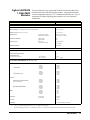
AGILENT TECHNOLOGIES WARRANTY STATEMENT
PRODUCT: Agilent 3499A/B/C Switch/Control System
DURATION OF WARRANTY: 1 year
1. Agilent Technologies warrants Agilent hardware, accessories and supplies against defects in materials and workmanship for the period
specified above. If Agilent receives notice of such defects during the warranty period, Agilent will, at its option, either repair or replace
products which prove to be defective. Replacement products may be either new or like-new.
2. Agilent Technologies warrants that Agilent software will not fail to execute its programming instructions, for the period specified
above, due to defects in material and workmanship when properly installed and used. If Agilent receives notice of such defects during
the warranty period, Agilent will replace software media which does not execute its programming instructions due to such defects.
3. Agilent Technologies does not warrant that the operation of Agilent products will be interrupted or error free. If Agilent is unable,
within a reasonable time, to repair or replace any product to a condition as warranted, customer will be entitled to a refund of the purchase
price upon prompt return of the product.
4. Agilent Technologies products may contain remanufactured parts equivalent to new in performance or may have been subject to
incidental use.
5. The warranty period begins on the date of delivery or on the date of installation if installed by Agilent. If customer schedules or delays
Agilent installation more than 30 days after delivery, warranty begins on the 31st day from delivery.
6. Warranty does not apply to defects resulting from (a) improper or inadequate maintenance or calibration, (b) software, interfacing, parts
or supplies not supplied by Agilent, (c) unauthorized modification or misuse, (d) operation outside of the published environmental
specifications for the product, or (e) improper site preparation or maintenance.
7. TO THE EXTENT ALLOWED BY LOCAL LAW, THE ABOVE WARRANTIES ARE EXCLUSIVE AND NO OTHER
WARRANTY OR CONDITION, WHETHER WRITTEN OR ORAL, IS EXPRESSED OR IMPLIED AND AGILENT
SPECIFICALLY DISCLAIMS ANY IMPLIED WARRANTY OR CONDITIONS OF MERCHANTABILITY, SATISFACTORY
QUALITY, AND FITNESS FOR A PARTICULAR PURPOSE.
8. Agilent Technologies will be liable for damage to tangible property per incident up to the greater of $300,000 or the actual amount paid
for the product that is the subject of the claim, and for damages for bodily injury or death, to the extent that all such damages are
determined by a court of competent jurisdiction to have been directly caused by a defective Agilent product.
9. TO THE EXTENT ALLOWED BY LOCAL LAW, THE REMEDIES IN THIS WARRANTY STATEMENT ARE CUSTOMER’S
SOLE AND EXLUSIVE REMEDIES. EXCEPT AS INDICATED ABOVE, IN NO EVENT WILL AGILENT OR ITS SUPPLIERS BE
LIABLE FOR LOSS OF DATA OR FOR DIRECT, SPECIAL, INCIDENTAL, CONSEQUENTIAL (INCLUDING LOST PROFIT OR
DATA), OR OTHER DAMAGE, WHETHER BASED IN CONTRACT, TORT, OR OTHERWISE.
FOR CONSUMER TRANSACTIONS IN AUSTRALIA AND NEW ZEALAND: THE WARRANTY TERMS CONTAINED IN THIS
STATEMENT, EXCEPT TO THE EXTENT LAWFULLY PERMITTED, DO NOT EXCLUDE, RESTRICT OR MODIFY AND ARE
IN ADDITION TO THE MANDATORY STATUTORY RIGHTS APPLICABLE TO THE SALE OF THIS PRODUCT TO YOU.
U.S. Government Restricted Rights
The Software and Documentation have been developed entirely at private expense. They are delivered and licensed as "commercial
computer software" as defined in DFARS 252.227- 7013 (Oct 1988), DFARS 252.211-7015 (May 1991) or DFARS 252.227-7014 (Jun
1995), as a "commercial item" as defined in FAR 2.101(a), or as "Restricted computer software" as defined in FAR 52.227-19 (Jun 1987)
(or any equivalent agency regulation or contract clause), whichever is applicable. You have only those rights provided for such Software
and Documentation by the applicable FAR or DFARS clause or the Agilent standard software agreement for the product involved.
Trademark Information
Visual BASIC, Visual C++, Windows 95 and Windows NT are U.S. registered trademarks of Microsoft Corporation.
s1
Agilent 3499A/B/C Switch/Control System Service Manual
Rev. E
Copyright © 2009 Agilent Technologies Company. All Rights Reserved.
i
Documentation History
All Editions and Updates of this manual and their creation date are listed below. The first Edition of the manual is Edition 1. The Edition
number increments by 1 whenever the manual is revised. Updates, which are issued between Editions, contain replacement pages to
correct or add additional information to the current Edition of the manual. Whenever a new Edition is created, it will contain all of the
Update information for the previous Edition. Each new Edition or Update also includes a revised copy of this documentation history page.
Rev. A . . . . . . . . . . . . . . . . . . . . . . . . . . . . . . . . . . . . . . . . . . . . . . . January 2000
Rev. B . . . . . . . . . . . . . . . . . . . . . . . . . . . . . . . . . . . . . . . . . . . . . December 2000
Rev. C . . . . . . . . . . . . . . . . . . . . . . . . . . . . . . . . . . . . . . . . . . . . . . . . . April 2002
Rev. D . . . . . . . . . . . . . . . . . . . . . . . . . . . . . . . . . . . . . . . . . . . . . . . . March 2003
Rev. E . . . . . . . . . . . . . . . . . . . . . . . . . . . . . . . . . . . . . . . . . . . . . . . . March 2009
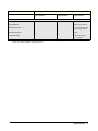
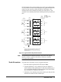
Safety Symbols
Instruction manual symbol affixed to
product. Indicates that the user must refer to
the manual for specific WARNING or
CAUTION information to avoid personal
injury or damage to the product.
Alternating current (AC)
Direct current (DC).
Indicates hazardous voltages.
Indicates the field wiring terminal that must
be connected to earth ground before
operating the equipment—protects against
electrical shock in case of fault.
or
Frame or chassis ground terminal—typically
connects to the equipment's metal frame.
Calls attention to a procedure, practice, or
WARNING condition that could cause bodily injury or
death.
Calls attention to a procedure, practice, or
CAUTION condition that could possibly cause damage to
equipment or permanent loss of data.
WARNINGS
The following general safety precautions must be observed during all phases of operation, service, and repair of this product. Failure to
comply with these precautions or with specific warnings elsewhere in this manual violates safety standards of design, manufacture, and
intended use of the product. Agilent Technologies Company assumes no liability for the customer's failure to comply with these
requirements.
Ground the equipment: For Safety Class 1 equipment (equipment having a protective earth terminal), an uninterruptible safety earth
ground must be provided from the mains power source to the product input wiring terminals or supplied power cable.
DO NOT operate the product in an explosive atmosphere or in the presence of flammable gases or fumes.
For continued protection against fire, replace the line fuse(s) only with fuse(s) of the same voltage and current rating and type. DO NOT
use repaired fuses or short-circuited fuse holders.
Keep away from live circuits: Operating personnel must not remove equipment covers or shields. Procedures involving the removal of
covers or shields are for use by service-trained personnel only. Under certain conditions, dangerous voltages may exist even with the
equipment switched off. To avoid dangerous electrical shock, DO NOT perform procedures involving cover or shield removal unless you
are qualified to do so.
DO NOT operate damaged equipment: Whenever it is possible that the safety protection features built into this product have been
impaired, either through physical damage, excessive moisture, or any other reason, REMOVE POWER and do not use the product until
safe operation can be verified by service-trained personnel. If necessary, return the product to an Agilent Technologies Sales and Service
Office for service and repair to ensure that safety features are maintained.
DO NOT service or adjust alone: Do not attempt internal service or adjustment unless another person, capable of rendering first aid and
resuscitation, is present.
DO NOT substitute parts or modify equipment: Because of the danger of introducing additional hazards, do not install substitute parts
or perform any unauthorized modification to the product. Return the product to an Agilent Technologies Sales and Service Office for
service and repair to ensure that safety features are maintained.
Operating Location: Sheltered location where air temperature and humidity are controlled within this product’s specifications and the
product is protected against direct exposure to climatic conditions such as direct sunlight, wind, rain, snow, sleet, and icing, water spray
or splash, hoarfrost or dew. Pollution environment for which this product may be operated is IEC 664 Pollution degree 2.
ii
WARNINGS (Cont.)
The Agilent 3499A/B/C can have modules that are capable of switching voltages up to 250V maximum. Voltage levels above the levels
specified for accessible connectors or cable ends could cause bodily injury or death to an operator. Special precautions must be adhered
to (discussed below) when applying voltages in excess of 60 Vdc, 30 Vac rms or 42.4 Vac peak.
Module connectors and test signal cables connected to them cannot be operator accessible. Cables and connectors are considered
inaccessible if a tool (e.g., screwdriver, wrench, socket, etc.) or a key (equipment in a locked cabinet) is required to gain access to them.
Additionally, the operator cannot have access to a conductive surface connected to any cable conductor (High, Low or Guard).
Assure the equipment under test has adequate insulation between the cable connections and any operator-accessible parts (doors,
covers, panels, shields, cases, cabinets, etc.). Verify there are multiple and sufficient protective means (rated for the voltages you are
applying) to assure the operator will NOT come into contact with any energized conductor even if one of the protective means fails to
work as intended. For example, the inner side of a case, cabinet, door, cover or panel can be covered with an insulating material as well
as routing the test cables to the module’s front panel connectors through non-conductive, flexible conduit such as that used in electrical
power distribution.
This ISM device complies with Canadian CES-001
Cet appareil ISM est conforme à la norme NMB-001 du Canada
CLEANING INFORMATION
The instrument should only be cleaned by wiping it with a soft damp cloth.
iii
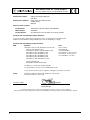
DECLARATION OF CONFORMITY
According to ISO/IEC Guide 22 and CEN/CENELEC EN 45014
Manufacturer’s Name:
Manufacturer’s Address:
Agilent Technologies (Malaysia)
Sdn. Bhd.
Bayan Lepas Free Industrial Zone
11900 Penang
Malaysia
Declares, that the product
Product Name:
Model Number:
Product Options:
Switch/Control System and Associated Modules
3499A/B/C
This declaration covers all options of the above products.
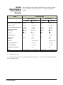
Conforms with the following European Directives:
The product herewith complies with the requirements of the Low Voltage Directive 73/23/EEC and the
EMC Directive 89/336/EEC (including 93/68/EEC) and carries the CE Marking accordingly.
Conforms with the following product standards:
EMC
Standard
Limit
IEC 61326-1:1997+A1:1998 / EN 61326-1:1997+A1:1998
CISPR 11:1990 / EN 55011:1991
IEC 61000-4-2:1995+A1:1998 / EN 61000-4-2:1995
IEC 61000-4-3:1995 / EN 61000-4-3:1995
IEC 61000-4-4:1995 / EN 61000-4-4:1995
IEC 61000-4-5:1995 / EN 61000-4-5:1995
IEC 61000-4-6:1996 / EN 61000-4-6:1996
IEC 61000-4-11:1994 / EN 61000-4-11:1994
Group 1 Class A
4kV CD, 8kV AD
3 V/m, 80-1000 MHz
0.5kV signal lines, 1kV power lines
0.5 kV line-line, 1 kV line-ground
3V, 0.15-80 MHz I cycle, 100%
Canada: ICES-001:1998
Australia/New Zealand: AS/NZS 2064.1
This ISM device complies with Canadian ICES-001.
Cet appareil ISM est conforme à la norme NMB-001 du Canada.
The product was tested in a typical configuration with Agilent Technologies test systems.
Safety
IEC 61010-1:1990+A1:1992+A2:1995 / EN 61010-1:1993+A2:1995
Canada: CSA C22.2 No. 1010.1:1992
January 17, 2002
Date
Tan Boon Juan
Quality Manager
For further information, please contact your local Agilent Technologies sales office, agent or distributor.
Authorized EU-representative: Agilent Technologies Deutschland GmbH, Herrenberger Straβe 130, D 71034 Böblingen, Germany
iv
Contents
Agilent 3499A/B/C Switch/Control System Service Manual
Legal and Safety Information .......................................................................................... i
AGILENT TECHNOLOGIES WARRANTY STATEMENT...................................... i
Trademark Information.................................................................................................. i
Safety Symbols ............................................................................................................. ii
WARNINGS ................................................................................................................. ii
CLEANING INFORMATION ....................................................................................iii
DECLARATION OF CONFORMITY ....................................................................... iv
Chapter 1
Specifications .................................................................................................................. 1
General Information...................................................................................................... 1
Agilent 3499A/B/C Mainframe’s Specifications.......................................................... 2
Plug-in Modules Specifications .................................................................................... 4
Multiplexer (MUX) Modules ................................................................................ 4
GP Relay Modules ................................................................................................ 8
Matrix Modules ................................................................................................... 11
Digital I/O Modules ............................................................................................ 12
Agilent N2269A Multifunction Module ............................................................. 13
Agilent 44472A VHF Switch Module ................................................................ 14
Agilent 44475A Breadboard Module .................................................................. 15
Agilent 44476A Microwave Switch Module ...................................................... 15
Agilent N2276A/B Microwave Switch Module .................................................. 16
Agilent 44477A Form-C Relay Module .............................................................. 17
Agilent 44478A/B 1.3GHz MUX Modules ........................................................ 18
Agilent N2280A/N2281A Optical Switch Modules ........................................... 19
Agilent N2282A Optical Switch Module ............................................................ 20
Chapter 2
Getting Started ............................................................................................................. 21
About This Chapter..................................................................................................... 21
To Prepare the Instrument for Use.............................................................................. 21
Check the List of Supplied Items ........................................................................ 21
Initial Inspection .................................................................................................. 21
Power on the Instrument ..................................................................................... 22
If the Instrument Does Not Turn On ................................................................... 22
Module Installation ..................................................................................................... 22
Module Installation ............................................................................................. 22
Module Removal ................................................................................................. 23
Operating the Instrument ............................................................................................ 24
Channel Addressing ............................................................................................ 24
Basic Front-Panel Operation ............................................................................... 27
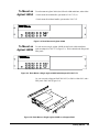
To Rack Mount the Agilent 3499A/B/C..................................................................... 28
To Mount an Agilent 3499A ............................................................................... 28
To Mount an Agilent 3499B ............................................................................... 29
To Mount an Agilent 3499C ............................................................................... 30
Contents
1
Chapter 3
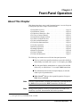
Front-Panel Operation ................................................................................................ 31
About This Chapter..................................................................................................... 31
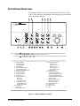
Front-Panel Overview................................................................................................. 32
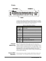
Display ................................................................................................................ 33
Channel Addressing ............................................................................................ 33
Channel/Slot Selection ........................................................................................ 33
Local/Remote Control................................................................................................. 34
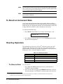
To Monitor a Channel or a Slot .................................................................................. 34
To Close or Open a Channel....................................................................................... 36
To Read from a Digital I/O Port ................................................................................. 36
To Write to a Digital I/O Port..................................................................................... 36
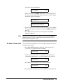
To Store an Instrument State ...................................................................................... 37
To Recall an Instrument State..................................................................................... 38
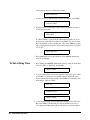
View Key Operation ................................................................................................... 38
To View an Error ................................................................................................. 38
To View a Scan List ............................................................................................ 39
To View the Relay Cycles ................................................................................... 40
Mode Key Operation .................................................................................................. 40
Agilent N2260A Configuration ........................................................................... 41
DIO Module Configuration ................................................................................. 42
DIO Port Configuration ....................................................................................... 43
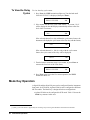
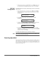
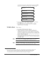
Scanning Operation..................................................................................................... 43
Overview ............................................................................................................. 44
To Create a Scan List .......................................................................................... 45
To Configure a Scan ............................................................................................ 45
To Set a Delay Time ............................................................................................ 46
To Start a Scan .................................................................................................... 47
Menu Key Operation .................................................................................................. 48
To Pair Two Cards .............................................................................................. 50
To Configure the External Trigger ...................................................................... 50
To Configure the Power-on State ........................................................................ 52
To Configure the Remote Interface ..................................................................... 53
To Perform a Self-test ......................................................................................... 54
To Select a System Mode .................................................................................... 54
To Query the Firmware Revision ........................................................................ 55
To Query the Serial Number ............................................................................... 55
To Reset a Module ...................................................................................................... 57
To Reset the Instrument.............................................................................................. 57
Chapter 4
Verification Tests ......................................................................................................... 59
About This Chapter..................................................................................................... 59
General Information.................................................................................................... 59
Mainframes Self-Test ................................................................................................. 60
Self-Test .............................................................................................................. 60
Correction ............................................................................................................ 61
Mainframe Verification Tests ..................................................................................... 61
2
Contents
GPIB Test ............................................................................................................ 61
RS-232 Test ......................................................................................................... 61
Keyboard Test ..................................................................................................... 62
Correction ............................................................................................................ 62
Relay Cycle Count ...................................................................................................... 62
MUX Modules Verification Tests .............................................................................. 62
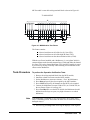
Test Fixture ......................................................................................................... 62
Tests Procedure ................................................................................................... 63
Correction ............................................................................................................ 64
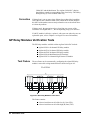
GP Relay Modules Verification Tests ........................................................................ 64
Test Fixture ......................................................................................................... 64
Tests Procedure ................................................................................................... 65
Correction ............................................................................................................ 65
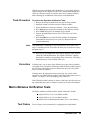
Matrix Modules Verification Tests............................................................................. 65
Test Fixture ......................................................................................................... 65
Tests Procedure ................................................................................................... 66
Correction ............................................................................................................ 67
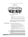
Digital I/O Modules Verification Tests ...................................................................... 67
Test Fixture ......................................................................................................... 67
Tests Procedure ................................................................................................... 68
Correction ............................................................................................................ 70
Agilent 44472A Verification Tests............................................................................. 70
Tests Procedure ................................................................................................... 70
Correction ............................................................................................................ 70
Agilent 44476A/B Verification Tests ......................................................................... 71
Tests Procedure ................................................................................................... 71
Correction ............................................................................................................ 72
Agilent 44477A Verification Tests............................................................................. 72
Test Fixture ......................................................................................................... 72
Tests Procedure ................................................................................................... 72
Correction ............................................................................................................ 73
Agilent 44478A/B Verification Tests ......................................................................... 74
Tests Procedure ................................................................................................... 75
Correction ............................................................................................................ 75
Agilent N2280A/81A/82A Verification Tests ............................................................ 76
Test Procedure ..................................................................................................... 77
Correction ........................................................................................................... 77
Chapter 5
Service ........................................................................................................................... 79
Introduction................................................................................................................. 79
Safety Considerations ................................................................................................. 79
Static Handing............................................................................................................. 79
Agilent 3499A/B/C Problem Isolation ....................................................................... 80
Preliminary Tests ................................................................................................. 80
Plug-in Module Substitution ............................................................................... 81
Mainframe Problem Isolation ..................................................................................... 81
Power Supply ...................................................................................................... 81
Contents
3
Controller ............................................................................................................ 82
Keyboard & Display ............................................................................................ 82
Backplane ............................................................................................................ 83
Chapter 6
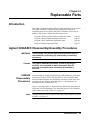
Replaceable Parts ......................................................................................................... 85
Introduction................................................................................................................. 85
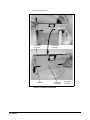
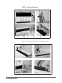
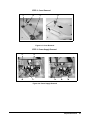
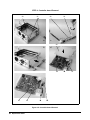
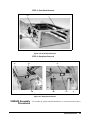
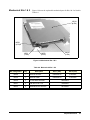
Agilent 3499A/B/C Disassembly/Assembly Procedures............................................ 85
3499A/B Disassembly Procedures ...................................................................... 85
3499A/B Assembly Procedures .......................................................................... 89
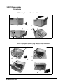
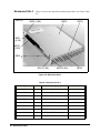
3499C Disassembly Procedures .......................................................................... 90
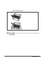
3499C Assembly Procedures .............................................................................. 91
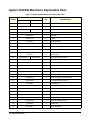
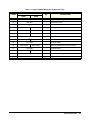
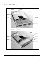
Agilent 3499A/B Mainframe Replaceable Parts ........................................................ 92
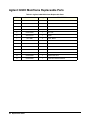
Agilent 3499C Mainframe Replaceable Parts ............................................................ 94
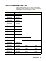
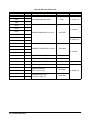
Plug-in Modules Replaceable Parts ............................................................................ 95
Mechanical Kits 1 & 2 ........................................................................................ 97
Mechanical Kits 3 ................................................................................................ 98
Mechanical Kits 4 & 5 ........................................................................................ 99
Mechanical Kits 6 .............................................................................................. 101
Mechanical Kits 7 .............................................................................................. 102
Mechanical Kits 8 .............................................................................................. 103
Mechanical Kits 9 .............................................................................................. 104
Mechanical Kits 10 ............................................................................................ 105
Mechanical Kits 11 ............................................................................................ 106
Mechanical Kits 12 ............................................................................................ 107
Mechanical Kits 13 ............................................................................................ 108
Mechanical Kits 14 ............................................................................................ 109
Appendix A
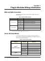
Plug-in Modules Wiring Information ...................................................................... 110
BNC and SMA Connection ...................................................................................... 110
Screw Terminal Blocks............................................................................................. 110
Crimp-and-insert Terminal Block............................................................................. 116
Connector Kits .......................................................................................................... 117
Agilent N2327A Wiring Sequence ................................................................... 117
Agilent N2320A Wiring Sequence ................................................................... 118
DIN-TO-D Cables..................................................................................................... 119
Appendix B
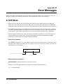
Error Messages .......................................................................................................... 122
In SCPI Mode ........................................................................................................... 122
In 3488A Mode ......................................................................................................... 128
Appendix C
Schematics .................................................................................................................. 129
4
Contents
Chapter 1
Specifications
General Information
The Agilent 3499A/B/C Switch/Control System is composed of three
mainframes and a set of plug-in modules. This chapter lists the
specifications of the three Agilent 3499A/B/C mainframes and all the
plug-in modules. These include:
• Agilent 3499A/B/C Mainframes Specifications . . . . . . . . . . Page 2
• Multiplexer (MUX) Modules Specifications . . . . . . . . . . . . Page 3
• GP Relay Modules Specifications. . . . . . . . . . . . . . . . . . . . . Page 7
• Matrix Modules Specifications . . . . . . . . . . . . . . . . . . . . . . . Page 10
• Digital I/O Modules Specifications. . . . . . . . . . . . . . . . . . . . Page 11
• Agilent N2269A Multifunction Module Specifications . . . . Page 12
• Agilent 44472A VHF Switch Module Specifications. . . . . . Page 13
• Agilent 44475A Breadboard Module Specifications . . . . . . Page 14
• Agilent 44476A Microwave Switch Module Specifications Page 14
• Agilent N2276A/B Microwave Switch Module SpecificationsPage 15
• Agilent 44477A Form-C Relay Module Specifications . . . . Page 16
• Agilent 44478A/B 1.3 GHz MUX Modules Specifications . Page 17
• Agilent N2280A/81A/82A Modules Specifications . . . . . . . Page 18
Specifications
1
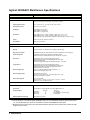
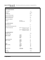
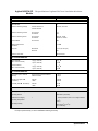
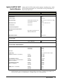
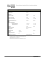
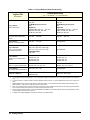
Agilent 3499A/B/C Mainframe’s Specifications
ITEMS
SPECIFICATIONS
General
Power Supply:
3499A/B: 100 to 240 VAC universal input; 47 Hz to 440 Hz; 90 VA;
3499C: 100 to 240 VAC universal input; 47 Hz to 63 Hz; 140 VA.
Operating Environment:
0 to 55oC (32 to 131oF); < 80% RH, 0 to 40oC (32 to 104oF).
Storage Environment:
-40 to +70oC (-40 to 158oF)
Net Weight:
Agilent 3499A: 3.8 kg (8.4 lbs);
Agilent 3499B: 2.5 kg (5.5 lbs).
Agilent 3499C: 7.4 kg (16.4 lbs).
Dimensions:
Agilent 3499A (H x W x L): 89mm x 426mm x 348mm (3.5” x 16.8” x 13.7”);
Agilent 3499B (H x W x L): 89mm x 213mm x 348mm (3.5” x 8.4” x 13.7”);
Agilent 3499C (H x W x L):221.5mm x 426mm x 353.5mm (8.7“ x 16.8“ x 13.9“).
Safety:
Conforms to CSA, UL-1244, IEC 1010 Cat I.
RFI and ESD:
CISPR 11, IEC 801/2/3/4.
System
Capacity:
5 Slots (Agilent 3499A) or 2 Slots (Agilent 3499B) or 9 slots (Agilent 3499C).
Display:
Vacuum fluorescent, 13 characters can be displayed simultaneously.
Rear Panel Connectors:
GPIB (IEEE-488); RS-232; 8-pin Mini DIN connector (4-bit Digital I/O, external triggers).
Switch Setting Time:
Automatically selected by the mainframe for individual modules;
Additional time from 0 to 99999.999 seconds can be added in 1 ms steps.
Arm Source:
External trigger (from the rear panel Mini DIN connector);
IEEE-488 bus (GET, *TRG, or pressing Step from the front-panel);
Software (TRIGger:IMM);
Internal timer (programmable as 0 to 99999.999 seconds in 1 ms steps).
Trigger Source:
External trigger (from the rear panel Mini DIN connector);
IEEE-488 bus (GET, *TRG, or pressing Step from the front-panel);
Software (Trigger:IMM); Internal timer (programmable as 0 to
99999.999 seconds in 1 ms steps).
External Trigger Input:
Level: TTL compatible; Minimum trigger pulse width: 2 µs;
Maximum external trigger delaya: 2 ms.
External Trigger Output:
Level: Normally pull up to 5 V;
Sink current: 10 mA @ Vo(Low) ≤ 0.4V; 80 mA @ Vo(Low) ≤ 0.8V;
Low going pulse width: 10 µs typical.
Built-in 4-bit Digital I/O:
Input: TTL compatible;
Output: Vo(high) ≥ 2.4V @ Io = 1 mA; Vo(Low) ≤ 0.8V @ Io = −100 mA;
Maximum Vo = 42V, with external pull-up.
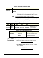
System Speedb
Scan Speed:
350 chans/sec (N2266A)
Parser Timec:
Open (@100): 3 ms; Close (@100): 3 ms; Open (@100:139): 4 ms
Switching Speed:
Open/Close:
Open/Close:
Open/Close:
Digital I/O Block Transfer Rate:
Channels
1
10
40
Time (ms)
7.1 (N2266A)
22.0 (N2266A, in the same group)
28.9 (N2266A)
20K bytes/sec (long word)
a. Maximum time from activation of external trigger pulse to start of switch open or close.
b. Just for reference. The system speed specification may vary in a small range due to the speed of the remote
PC, the GPIB module, the version of VISA and the version of 3499A/B/C’s firmware used.
c. Measured from the time at which the command terminator is taken from the bus to the time at which the relay
begins to open or close.
2 Specifications
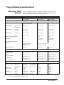
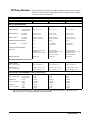
Plug-in Modules Specifications
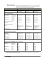
Multiplexer (MUX)
Modules
The MUX modules available with Agilent 3499A/B/C include: Agilent
N2260A, 44470A/D, N2266A, N2268A and N2270A. Specifications of
these MUX modules are listed in the following tables.
ITEMS
SPECIFICATIONS
Agilent N2260A
Agilent 44470A
Agilent 44470D
80 1-wire; or 40 2-wire;
or dual 20 2-wire; or 20 4-wire
10 (2-wire)
20 (2-wire)
INPUT CHARACTERISTICS
Total Channels:
Maximum Voltage
Terminal-Terminal
or
Terminal-Chassis:
200 V, dc or ac rms
250 V, dc or ac rms
250 V, dc or ac rms
Maximum Current
Per Channel:
1 A, dc or ac rms
2 A, dc or ac rms
2 A, dc or ac rms
Per Module:
2A, dc or ac rms
2 A, dc or ac rms
2 A, dc or ac rms
Per Channel:
60 W dc; 62.5 VA ac
60 W dc; 500 VA ac
60 W dc; 125 VA ac
Per Module:
120 W dc; 125 VA ac
60 W dc; 500 VA ac
60 W dc; 125 VA ac
Maximum Overvoltage Transients:
N/A
1400 Vpk
1400 Vpk
Thermal Offset:
< 3 µV
< 3 µV differential
or single-ended
< 3 µV differential
or single-ended
Initial Closed Channel Resistance:
<1Ω
<1Ω
<1Ω
Relay Life:
Mechanical: 108 (at 36000
operations/hour)
Electrical: 5 x 10⁵ (1A load)
108 (dry load of < 300 mA & < 10 V)
105 (maximum rated load)
80 Chans/sec
43 Chans/sec
43 Chans/sec
Open Channel,
Channel-Channel
(with 1 channel closed)
< (40oC, 50% RH): > 1010 Ω
< (40oC, 80% RH): > 109 Ω
< (40oC, 60% RH): > 1011 Ω
< (40oC, 95% RH): > 109 Ω
< (40oC, 60% RH): > 1011 Ω
< (40oC, 95% RH): > 5x10⁹ Ω
HI-LO
(with 1 channel closed)
< (40oC, 50% RH): > 1010 Ω
< (40oC, 80% RH): > 109 Ω
< (40oC, 60% RH): > 1010 Ω
< (40oC, 95% RH): > 108 Ω
< (40oC, 60% RH): > 5x10¹⁰ Ω
< (40oC, 95% RH): > 109 Ω
Channel-Chassis
(with 1 channel closed)
< (40oC, 50% RH): > 1010 Ω
< (40oC, 80% RH): > 109 Ω
< (40oC, 60% RH): > 1010 Ω
< (40oC, 95% RH): > 5x10⁸ Ω
< (40oC, 60% RH): > 5x10¹⁰ Ω
< (40oC, 95% RH): > 109 Ω
< 5 pF
< 27 pF
< 80 pF
< 7 pF
< 27 pF
< 80 pF
< 0.20 dB
< 0.25 dB
< 0.50 dB
< 0.20 dB
< 0.25 dB
< 1.20 dB
< -73 dB
< -53 dB
< -33 dB
< -73 dB
< -53 dB
< -31 dB
Maximum Power
Maximum Scan Rate:
DC ISOLATION (with terminal block)
AC ISOLATION / PERFORMANCEa (without terminal block)
Capacitance
(with 1 channel closed)
Open Channel,
Channel-Channel:
HI-LO:
Channel-Chassis:
< 7 pF (2-wire)
< 75 pF (2-wire)
< 150 pF (2-wire)
Insertion Loss
(with 50Ω termination)
100 kHz:
1 MHz:
10 MHz:
< 0.10 dB
< 0.20 dB
< 1.50 dB
Crosstalk
(with 50Ω termination)
100 kHz:
1 MHz:
10 MHz:
< -70 dB (2-wire)
< -50 dB (2-wire)
< -30 dB (2-wire)
< 7 pF (dual 2-wire)
< 45 pF (dual 2-wire)
< 90 pF (dual 2-wire)
< -40 dB (1-wire)
< -25 dB (1-wire)
N/A (1-wire)
a. With chassis of all instruments connected, and with the Low Terminal of the input connected to the Low Terminal of the output (either
directly or via Agilent 3499A/B/C switching channels).
Specifications
3
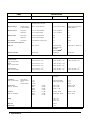
ITEMS
SPECIFICATIONS
Agilent N2266A
Agilent N2268A
Agilent N2270A
80 1-wire; or 40 2-wire;
or dual 20 2-wire; or 20 4-wire
Dual 1-to-4 Chans
10 (2-wire)
INPUT CHARACTERISTICS
Total Channels
Maximum Voltage
Terminal-Terminal
or Terminal-Chassis
200 V, dc or peak AC Resist.
30 V, dc or peak AC Resist.
1000 V peak (per IEC1010 for
Pollution Degree I)
Maximum Current
Per Channel
0.5 A, dc or peak AC Resist.
0.5 A, dc or peak AC
1A
Per Module
1 A, dc or peak AC Resist.
1 A, dc or peak AC
1A
Per Channel
10 W dc or peak AC Resist.
10 W
10 W
Per Module
20 W dc or peak AC Resist.
20 W
10 W
Per Channel
50 µV differential or single-ended
3 µV
200 µV
Initial Closed Channel Resistance
<1Ω
<1Ω
<1Ω
Relay Life
109 (at 1V/1mA)
mechanical: 5X10⁶
10mA/24VDC resist.
load:3X10⁵
10W 2.5G 50W: 105
Signal Load (1 V 10 mA): 108
Maximum Scan Rate
350 Chans/sec
20 Chans/sec
43 Chans/sec
Open Channel,
Channel-Channel
(with 1 channel closed)
< (40oC, 50% RH): > 1010 Ω
< (40oC, 80% RH): > 109 Ω
< (40oC, 50% RH): > 1010 Ω
< (40oC, 80% RH): > 109 Ω
< (40oC, 50% RH): > 1010 Ω
< (40oC, 80% RH): > 109 Ω
HI-LO
(with 1 channel closed)
< (40oC, 50% RH): > 1010 Ω
< (40oC, 80% RH): > 109 Ω
< (40oC, 50% RH): > 1010 Ω
< (40oC, 80% RH): > 109 Ω
Channel-Chassis
(with 1 channel closed)
< (40oC, 50% RH): > 1010 Ω
< (40oC, 80% RH): > 109 Ω
< (40oC, 50% RH): > 1010 Ω
< (40oC, 80% RH): > 109 Ω
40 MHz
3.0 GHz (50W source, 50W
termination)
Maximum Power
Thermal Offset
DC CHARACTERISTICS
< (40oC, 50% RH): > 1010 Ω
< (40oC, 80% RH): > 109 Ω
AC CHARACTERISTICSa
Bandwidth (-3dB)
Capacitance
(with 1 channel closed)
Open Channel,
Channel-Channel:
HI-LO:
Channel-Chassis:
< 7 pF
< 50 pF
< 140 pF
20 pF (Center-Shield)
0.06 pF (Center-Center)
< 7 pF
< 7 pF
< 50 pF
Insertion Loss
(with 50Ω termination)
100 kHz
1 MHz
10 MHz
40MHz
< 0.2 dB
< 0.3 dB
< 2.0 dB
< 3.0 dB
1 GHz: 0.9 dB
2 GHz: 1.2 dB
3.0 GHz: 1.7 dB
100 kHz: 0.1 dB
1 MHz: 0.2 dB
Crosstalk
(with 50Ω termination)
100 kHz
1 MHz
10 MHz
< -75 dB
< -55 dB
< -33 dB
DC-2GHz: -64 dB
2GHz-3.0GHz: -50 dB
100 kHz: -70 dB
1 MHz: -50 dB
VSWR
1 GHz: 1.20
2 GHz: 1.35
3.0 GHz: 1.35
Rise Time
< 150 ps
Signal Delay
< 1.5 ns
4 Specifications
ITEMS
SPECIFICATIONS
Agilent N2266A
Agilent N2268A
Agilent N2270A
Environmental Conditions
Operating Pollution Degree
2
Operating Altitude
3000 meters (10,000 ft)
Measurement Category
I
I, 1500 Vpk transient, 500
V over voltage transient
Operating Temperature
0-55oC
Operating Humidity
<80% RH (0oC-40oC),
non-condensing
a. With chassis of all instruments connected, and with the Low Terminal of the input connected to the Low Terminal of the output (either
directly or via Agilent 3499A/B/C switching channels).
Specifications
5
Agilent N2272A 1-to-9 RF
MUX Module
The following table lists the specifications of Agilent N2272A.
ITEMS
SPECIFICATIONS
INPUT CHARACTERISTICS
Total Channels
1-to-9
Relay Type
Latching
Connector Type
BNC
Maximum Switching Voltage
24VDC
Maximum Switching Current
1A
Maximum Switching Power
24W
Characteristic Impedance
50Ω
Relay Life
Mechanical
Electrical@1A24VDC
5X10⁶
105
DC CHARACTERISTICS
Offset Voltage (mV)
8.0
Initial Closed Channel Resistance (W)
0.8
Insulation Resistance (W)
@(25oC, 40%RH) (Open Ch, Ch-Ch)
(Ch-Chassis, Ch-Center)
o
@(40 C, 80%RH) (Open Ch, Ch-Ch)
(Ch-Chassis, Ch-Center)
1010
1010
109
109
AC CHARACTERISTICS
Bandwidth (-3dB)
Insertion Loss (dB)
@(25oC, 40%RH)
Ch-Ch Cross Talk (dB)
@(25oC, 40%RH)
VSWR
@(25oC, 40%RH)
Capacitance (pF)
6
1GHz
100MHz
300MHz
500MHz
800MHz
1GHz
0.5
0.8
1.0
1.8
2.5
100MHz
300MHz
500MHz
800MHz
1GHz
-75
-65
-65
-55
-50
100MHz
300MHz
500MHz
800MHz
1GHz
1.20
1.30
1.35
1.35
1.55
Center-Shield
Center-Center
60 pF
0.006 pF
Rise Time
500 ps
Signal Delay
2.5 ns
Specifications
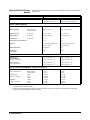
GP Relay Modules
The General Purpose (GP) relay modules include: Agilent N2261A, Agilent
44471A/D, Agilent N2264A and Agilent N2267A. Specifications of them
are listed in the following tables.
ITEMS
SPECIFICATIONS
Agilent N2261A
Agilent 44471A
Agilent 44471D
40
10
20
INPUT CHARACTERISTICS
Total Channels:
Maximum Voltage
Terminal-Terminal
or Terminal-Chassis:
200 V, dc or ac rms
250 V, dc or ac rms
250 V, dc or ac rms
Maximum Current
Per Channel:
Per Module:
1 A, dc or ac rms
20 A, dc or ac rms
2 A, dc or ac rms
20 A, dc or ac rms
1A, dc or ac rms
20 A, dc or ac rms
Maximum Power
Per Channel:
Per Module:
60 W dc; 62.5 VA ac
1200 W dc; 1250 VA ac
60 W dc; 500 VA ac
600 W dc; 5000 VA ac
60 W dc; 125 VA ac
1200 W dc; 2500 VA ac
Maximum Overvoltage Transients:
N/A
1400 Vpk
1400 Vpk
Thermal Offset
< 3 µV
< 3 µV different
or single-ended
< 3 µV different
or single-ended
Initial Closed Channel Resistance:
< 0.5 Ω
<1Ω
<1Ω
Relay Life
Mechanical: 108 (at 36000
operations/hour)
Electrical: 5 x 10⁵ (1A load)
108 operations/chan
(dry load of < 300 mA & < 10 V)
105 operations/chan
(maximum rated load)
108 operations/chan
(dry load of < 300 mA & < 10 V)
105 operations/chan
(maximum rated load)
Maximum Scan Rate:
80 Chans/sec
43 Chans/sec
43 Chans/sec
Per Channel:
DC ISOLATION (with terminal block)
Open Channel,
Channel-Channel
(with 1 channel closed)
< (40oC, 50% RH): > 1010 Ω
<
Channel-Chassis
(with 1 channel closed)
(40oC,
80% RH): >
109 Ω
< (40oC, 60% RH): > 1011 Ω
<
(40oC,
95% RH): >
109 Ω
< (40oC, 60% RH): > 1011 Ω
< (40oC, 95% RH): > 109 Ω
< (40oC, 50% RH): > 1010 Ω
< (40oC, 60% RH): > 5x10¹¹ Ω
< (40oC, 60% RH): > 5x10¹¹ Ω
< (40oC, 80% RH): > 109 Ω
< (40oC, 95% RH): > 1010 Ω
< (40oC, 95% RH): > 1010 Ω
AC ISOLATION / PERFORMANCEa (without terminal block)
Capacitance
(with 1 channel closed)
Open Channel:
Channel-Channel:
Channel-Chassis:
< 10 pF
< 10 pF
< 20 pF
< 7 pF
< 10 pF
< 25 pF
< 7 pF
< 10 pF
< 25 pF
Insertion Loss
(with 50Ω termination)
100 kHz:
1 MHz:
10 MHz:
< 0.10 dB
< 0.20 dB
< 0.50 dB
< 0.20 dB
< 0.25 dB
< 0.50 dB
< 0.20 dB
< 0.25 dB
< 1.00 dB
Crosstalk
(with 50Ω termination)
100 kHz:
1 MHz:
10 MHz:
< -70 dB
< -50 dB
< -30 dB
< -73 dB
< -53 dB
< -33 dB
< -71 dB
< -51 dB
< -31 dB
a. With chassis of all instruments connected, and with Low Terminal of the input connected to Low Terminal of the
output (either directly or via Agilent 3499A/B/C switching channels)
Specifications
7
Agilent N2264A GP Relay
Module
The specifications of the GP relays on an Agilent N2264A are listed in the
table below.
ITEMS
SPECIFICATIONS
Agilent N2264Aa
Agilent N2264A
(12-Channel GP function)
(3-Channel High-current GP function)
12
3
INPUT CHARACTERISTICS
Total Channels:
Maximum Voltage
Terminal-Terminal
or Terminal-Chassis:
200 V, dc or ac rms
125 V dc or 200 V ac rms
Maximum Current
Per Channel:
1 A, dc or ac rms
5A, dc or ac rms
Maximum Power
Per Channel:
60 W dc; 62.5 VA ac
150 W dc; 1250 VA ac
Thermal Offset
Per Channel:
< 3 µV
< 3 µV
Initial Closed Channel Resistance:
< 0.5 Ω
< 0.1 Ω
Relay Life
108 (at 36000 operations/hour)
5 x 10⁵ (1A load)
5 x 10⁷ (at 180 cycles/minute)
105 (at rated load)
Maximum Scan Rate:
80 Chans/sec
N/A
Time to Close
One Channel:
N/A
16 ms
DC ISOLATION (with terminal block)
Open Channel,
Channel-Channel
(with 1 channel closed)
< (40oC, 50% RH): > 1010 Ω
Channel-Chassis
(with 1 channel closed)
< (40oC, 50% RH): > 1010 Ω
<
<
(40oC,
(40oC,
80% RH): >
80% RH): >
109 Ω
109 Ω
< (40oC, 50% RH): > 1010 Ω
< (40oC, 80% RH): > 109 Ω
< (40oC, 50% RH): > 1010 Ω
< (40oC, 80% RH): > 109 Ω
AC ISOLATION / PERFORMANCEb (without terminal block)
Capacitance
(with 1 channel closed)
Open Channel:
Channel-Channel:
Channel-Chassis:
< 10 pF
< 10 pF
< 20 pF
< 10 pF
< 10 pF
< 20 pF
Insertion Loss
(with 50Ω termination)
100 kHz:
1 MHz:
10 MHz:
< 0.10 dB
< 0.20 dB
< 0.50 dB
< 0.10 dB
< 0.20 dB
< 0.50 dB
Crosstalk
(with 50Ω termination)
100 kHz:
1 MHz:
10 MHz:
< -70 dB
< -50 dB
< -30 dB
< -70 dB
< -50 dB
< -30 dB
a. Agilent N2264A combines a 12-channel GP, a 3-channel high-current GP and a 16-bit digital I/O into one module. It can be
operated as three separate modules.
b. With chassis of all instruments connected, and with Low Terminal of the input connected to Low Terminal of the output (either
directly or via Agilent 3499A/B/C switching channels)
8 Specifications
Agilent N2267A GP
Module
The specifications of Agilent N2267A are listed in the table below.
ITEMS
SPECIFICATIONS
INPUT CHARACTERISTICS
Total Channels
8
Maximum Switching Voltage
Terminal-Terminal or
Terminal-Chassis
250 VAC, 125 VDC
Maximum Switching Current
Per Channel
Per Module
8A
64 A
Maximum Switching Power
Per Channel
Per Module
2000 VA, 150 W
16000 VA, 1200 W
Thermal Offset
Per Channel
3 mV
< 0.08 W
Initial Closed Channel
Resistance
Relay Life
Mechanical
Electrical
Maximum Scan Rate
5 x 10⁷ (at 180 cpm)
105
20 Channs/sec
DC CHARACTERISTICS
Open ChannelL
(with 1 channel closed)
Channel-Chassis
(with 1 channel closed)
< (40oC, 50% RH)
<
(40oC,
80% RH)
< (40oC, 50% RH)
>1010 W
>109 W
>1010 W
< (40 C, 80% RH)
>109 W
Capacitance (with 1 channel
closeed)
Open Channel, Channel-Channel
Channel-Chassis
< 10 pF
< 10 pF
Insertion Loss (with 50W
termination)
100 kHz
1 MHz
0.10 dB
0.20 dB
Crosstalk (with 50W termination)
100 kHz
1 MHz
-75 dB
-55 dB
o
AC CHARACTERISTICSa
Environmental Conditions
Operating Pollution Degree
2
Operating Altitude
3000 meters (10,000 ft)
Measurement Category
I
I, 1500 Vpk transient, 500 V over voltage transient
Operating Temperature
0-55oC
Operating Humidity
<80% RH (0oC to 40oC)
non-condensing
a. With chassis of all instruments connected, and with Low Terminal of the input connected to Low Terminal of
the output (either directly or via the 3499A/B/C switching channels)
Specifications
9
Matrix Modules
The matrix modules include: Agilent N2262A 4 x 8 2-wire matrix, Agilent
44473A 4 x 4 2-wire matrix and the 4 x 4 2-wire matrix on an Agilent
N2265A. The specifications are listed in the table below.
ITEMS
SPECIFICATIONS
Agilent N2265Aa
Agilent N2262A
Agilent 44473A
(4 x 4 Matrix)
INPUT CHARACTERISTICS
Total Channels:
4x8
4x4
4x4
Terminal-Terminal or
Terminal-Chassis:
200 V, dc or ac rms
200 V, dc or ac rms
250 V, dc or ac rms
Maximum Current
Per Channel:
Per Module:
1 A, dc or ac rms
4 A, dc or ac rms
1 A, dc or ac rms
4 A, dc or ac rms
2 A, dc or ac rms
8 A, dc or ac rms
Maximum Power
Per Channel:
Per Module:
60 W dc; 62.5 VA ac
240 W dc; 250 VA ac
60 W dc; 62.5 VA ac
240 W dc; 250 VA ac
60 W dc; 500 VA ac
240 W dc; 2000 VA ac
Maximum Overvoltage Transients
N/A
N/A
1400 Vpk
Thermal Offset:
< 3 µV differential
< 3 µV differential
< 3 µV differential
Initial Closed Channel Resistance:
<1Ω
<1Ω
<1Ω
Relay Life
Mechanical: 108 (at 36000
operations/hour)
Electrical: 5 x 10⁵ (1A load)
Mechanical: 108
(at 36000 operations/hour)
Electrical: 5 x 10⁵ (1A load)
108 operations/chan (dry load
of < 300 mA & < 10 V)
105 operations/chan
(maximum rated load)
Maximum Scan Rate:
80 Chans/sec
80 Chans/sec
43 Chans/sec
Open Channel,
Channel-Channel
(with 1 channel closed)
< (40oC, 50% RH): > 1010 Ω
< (40oC, 50% RH): > 1010 Ω
< (40oC, 60% RH): > 1011 Ω
< (40oC, 80% RH): > 109 Ω
< (40oC, 80% RH): > 109 Ω
< (40oC, 95% RH): > 109 Ω
HI-LO
(with 1 channel closed)
< (40oC, 50% RH): > 1010 Ω
< (40oC, 50% RH): > 1010 Ω
< (40oC, 60% RH): > 1010 Ω
< (40 C, 80% RH): > 10 Ω
< (40 C, 80% RH): > 10 Ω
< (40oC, 95% RH): > 108 Ω
Channel-Chassis
(with 1 channel closed)
< (40oC, 50% RH): > 1010 Ω
< (40oC, 50% RH): > 1010 Ω
< (40oC, 60% RH): > 1010 Ω
< (40oC, 80% RH): > 109 Ω
< (40oC, 80% RH): > 109 Ω
< (40oC, 95% RH): > 5x10⁸ Ω
Maximum Voltage
DC ISOLATION (with terminal block)
o
9
o
9
AC ISOLATION / PERFORMANCEb (without terminal block)
Capacitance
(with 1 channel closed)
Open Channel,
Channel-Channel:
HI-LO:
Channel-Chassis:
< 7 pF
< 30 pF
< 50 pF
< 7 pF
< 25 pF
< 40 pF
< 5 pF
< 40 pF
< 70 pF
Insertion Loss
(with 50Ω termination)
100 kHz:
1 MHz:
10 MHz:
< 0.10 dB
< 0.20 dB
< 0.60 dB
< 0.10 dB
< 0.20 dB
< 0.60 dB
< 0.30 dB
< 0.35 dB
< 0.90 dB
Crosstalk
(with 50Ω termination)
100 kHz:
1 MHz:
10 MHz:
< -73 dB
< -53 dB
< -28 dB
< -76 dB
< -56 dB
< -33 dB
< -76 dB
< -56 dB
< -36 dB
a. Agilent N2265A combines a 4 x 4 matrix and a 16-bit digital I/O into one module. It can be operated as two separate modules.
b. With chassis of all instruments connected, and with Low Terminal of the input connected to Low Terminal of the output (either
directly or via Agilent 3499A/B/C switching channels).
10
Specifications
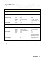
Digital I/O Modules
The digital I/O modules available with Agilent 3499A/B/C include: Agilent
N2263A 32-bit digital I/O, Agilent 44474A 16-bit digital I/O module and
the 16-bit digital I/O on both the Agilent N2264A/65A multifunction
modules. The specifications are listed in the table below.
ITEMS
SPECIFICATIONS
Agilent N2263A/64A/65Aa
Agilent 44474A
32/16/16
16
I/O LINES
Bit Number:
Maximum Voltage
Line-Chassis:
+ 42 V dc
+ 30 V dc
Maximum Sink Current
Per Bit:
600 mA
125 mA
Output Characteristics
Vout (high):
Vout (low):
I (low):
≥ 2.4 V @ I ≤ 10 mA output
≤ 0.8 V @ I ≤ 600 mA input
N/A
≥ 2.4 V @ I ≤ 8 mA output
≤ 0.4 V @ I ≤ 16 mA input
= 125 mA @ Vout (low) ≤ 1.25 V
I (low) is fused at 250 mA
Input Characteristics
Vin (high):
Vin (low):
≥ 2.0 V
≤ 0.8 V
≥ 2.0 V
≤ 0.8 V
Maximum Voltage
Line-Chassis:
+ 5 V dc
+ 5 V dc
Output Characteristics
Vout (high):
Vout (low):
Iout (low):
≥ 2.4 V @ I ≤ 400 µA output
≤ 0.5 V @ I ≤ 1 mA input
< 25 mA (when shorted to +5 V)
≥ 2.4 V @ I ≤ 400 µA output
≤ 0.5 V @ I ≤ 2 mA input
N/A
Input Characteristics
Vin (high):
Vin (low):
≥ 2.0 V
≤ 0.8 V
≥ 2.0 V
≤ 0.8 V
External Increment (EI)b:
N/A
Advance Agilent 3499A to next
programmed configuration on
falling edge of TTL pulse, 0.25
µsec minimum width.
Channel Closed (CC)c:
N/A
Indicates completion of new
configuration; TTL pulse, 10 µsec
minimum width.
HANDSHAKE LINES
a. Both the Agilent N2264A and N2265A are multifunction modules, the specifications listed in this table are for the 16-bit digital
I/O function on the Agilent N2264A and N2265A.
b. Both EI and CC lines are used for external controlled scanning. This item is for Agilent 44474A only.
c. When the next channel closes, the Agilent 44474A outputs a CC pulse to trigger the voltmeter. This item is for Agilent 44474A
only.
Specifications
11
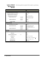
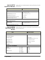
Agilent N2269A
Multifunction
Module
The following table lists Agilent N2269A module’s specifications.
ITEMS
SPECIFICATIONS
DIGITAL I/O LINES
maximum Voltage (line-to-chassis)
+5.25 VDC
Maximum Sink Current (per bit)
16 mA
Maximum Block Transfer Rate
Up to 3.57 M by 16 bit/s
Output Characteristics
Vout (high)
Vout (low)
>=2.4 V @|<=10 mA output
<=0.8 V @|<=16 mA input
Input Characteristics
Vin (high)
Vin (low)
>=2.0 V
<=0.8 V
Isolation Voltage
350 VDC
HANDSHAKE LINES
Maximum Voltage (line-to-chassis)
+5 VDC
Output Characteristics
Vout (high)
Vout (low)
Iout (low)
>=2.4 V @|<=400 mA output
<=0.5 V @|<=1 mA input
<=25 mA (when shorted to +5V)
Input Characteristics
Vin (high)
Vin (low)
>=2.0 V
<=0.8 V
DAC LINES
Analog Output Range
+12 V, non-isolated
Resolution
Maximum Output Current
Setting Time
Accuracy
12
1 mV
Iout
10 mA
1 ms to 0.01% of Output
0.04% of Output + 4mV @24hour+1oC
Temp Coefficient
+(0.015% of Output + 1mV)
Data Update Rate
781.25 KHz
Specifications
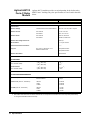
Agilent 44472A VHF
Switch Module
Agilent 44472A VHF Switch module contains 14 latching relays, which
provides dual independent 4-to-1 coaxial MUXs. The specifications are
listed in the table below.
ITEMS
SPECIFICATIONS
INPUT CHARACTERISTICS
Total Channels:
dual 4
Connector Type:
BNC (x10)
Maximum Voltage
Center-Center or Center-Low:
Low-Chassis or Low-Low:
250 V dc, 30 V ac rms or 42 V ac peak
42 V dc
Maximum Current
Per Channel:
30 mA dc, 300 mA ac rms
Thermal Offset
Per Channel:
< 15 µV
Characteristic Impedance:
50 Ω
Initial Closed Channel Resistance:
<1Ω
Relay Life
Dry Load of < 300 mA & < 10 V:
Maximum Rated Load:
108
105
43 Chans/sec
Maximum Scan Ratea:
DC ISOLATION
Between Any Two Points
< (40oC, 95% RH):
> 107 Ω
Center-Center, Center-Common:
Center-Low:
Low-Chassis:
< 0.002 pF
< 70 pF
< 0.20 µF
AC ISOLATION / PERFORMANCEb
Capacitance
Rise Time:
< 0.7 ns
Signal Delay:
< 2.5 ns (channel match < 90 ps)
Insertion Loss (with 50Ω termination)
30 MHz:
100 MHz:
300 MHz:
< 0.50 dB
< 0.75 dB
< 1.25 dB
Crosstalk Within a Group
(Channel-Channel or Channel-Common,
with 50Ω termination)
30 MHz:
100 MHz:
300 MHz:
< -100 dB
< -85 dB
< -65 dB
Crosstalk Group to Group
(with 50Ω termination)
30 MHz:
100 MHz:
300 MHz:
< -85 dB
< -85 dB
< -50 dB
VSWR (with 50 Ω termination)
30 MHz:
100 MHz:
300 MHz:
< 1.06
< 1.12
< 1.43
a. Using Agilent 44474A external increment & channel closed, display off.
b. When all channels in a group are opened, the last channel opened (or channel 00 or 13 following a group RESET) has
channel-common isolation of > 80 dB @ 30 MHz, > 60 dB @ 100 MHz, and > 40 dB @ 300 MHz.
Specifications
13
Agilent 44475A
Breadboard Module
Agilent 44475A is a breadboard module, and the specifications are listed in
the table below.
ITEMS
SPECIFICATIONS
MODULE DIMENTIONS
Component Area Available:
104mm x 74mm and 79mm x 74mm
(4.1” x 2.9” and 3.1” x 2.9”)
Grid Hole Spacing (center-center):
2.54mm x 2.54 mm (0.1” x 0.1”)
Grid Hole Size (inside diameter):
1.17mm (0.046”)
Maximum Component Height (above board):
12.7mm (0.5”)
Maximum lead Length (below board):
3.2mm (0.125”)
INPUT CHARACTERISTICS
Maximum Voltage:
42 V dc, 30 V ac rms, 42 V ac peak (on Breadboard area)
5.5 V (on Digital Input port lines)
Maximum Power Dissipation (per module):
2 Watt
Agilent 44476A
Microwave Switch
Module
Agilent 44476A is a microwave switch module, the specifications of it are
listed in the table below:
ITEMS
SPECIFICATIONS
INPUT CHARACTERISTICS
Frequency Range:
DC to 18 GHz
Characteristic Impedance:
50 Ω
Input Power Rating:
1 Watt average,
100 Watts peak (Also less than ±7 V dc)
Average Switch Life:
106 operations per channel
Repeatability (typical):
0.03 dB after 106 switchings
Maximum Scan Ratea:
43 Chans/sec
Connector:
SMA
AC ISOLATION / PERFORMANCE
Isolation
DC - 18 GHz:
> 90 dB
Insertion Loss
DC - 2 GHz:
DC - 18 GHz:
< 0.25 dB
< 0.50 dB
VSWR (3 mm SMA)
DC - 2 GHz:
DC - 12.4 GHz:
DC - 18.0 GHz:
< 1.15
< 1.25
< 1.40
a. Using Agilent 44474A External Increment & Channel Closed, display off.
14
Specifications
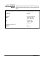
Agilent N2276A/B
Microwave Switch
Module
Agilent N2276A’s specifications are listed in the table below. Since the
switching and attenuation characteristics of the N2276B are determined by
the switches and attenuators installed in it, please refer to the switch’s and/or
attenuator’s data sheet for the specifications of your customized N2276B
module.
ITEMS
SPECIFICATIONS
Total Channels
Dual 1-to-6 (Dual 1-to-4 when with option 204)
Connector Type
SMA (female)
Frequency Range
DC to 20 GHz
Insertion Loss
0.3 dB + 0.015*Frequency (GHz)
Isolation
100 dB min. DC to 12GHz
80 dB min. 12GHz to 15GHz
70 dB min. 15GHz to 20GHz
SWR
1.2 max DC to 4GHz
1.35 max 4 to 12.4GHz
1.45 max 12.4 to 18GHz
1.7 max 18 to 20 GHz
Repeatability (5 million cycles at 25oC)
0.03dB maximum
Switch Speed
25ms
Switch Life
5 million cycles
Specifications
15
Agilent 44477A
Form-C Relay
Module
Agilent 44477A module provides seven independent, break-before-make,
SPDT Form-C latching relays, the specifications of it are listed in the table
below.
ITEMS
SPECIFICATIONS
INPUT CHARACTERISTICS
Total Channels:
7
Maximum Voltage
Terminal-Terminal or Terminal-Chassis:
250 V dc or ac rms, 350 V ac peak
Maximum Current
Per Channel:
Per Module:
2 A, dc or ac rms
14 A, dc or ac rms
Maximum Power
Per Channel:
Per Module:
60 W dc; 500 VA ac
420 W dc; 3500 VA ac
Maximum Overvoltage Transients:
1400 Vpk
Thermal Offset:
< 3 µV per channel
Initial Closed Channel Resistance:
<1Ω
Relay Life
Dry Load of < 300 mA & < 10 V:
Maximum Rated Load:
108 operations/chan
105 operations/chan
43 Chans/sec
Maximum Scan Ratea:
DC ISOLATION
Open Channel, Channel-Channel
(with 1 channel closed)
≤ (40oC, 60% RH):
> 1011 Ω
≤ (40 C, 95% RH):
>109 Ω
Channel-Chassis
(with 1 channel closed)
≤ (40oC, 60% RH):
> 5 x 10¹¹ Ω
≤ (40 C, 95% RH):
> 1010 Ω
Capacitance (with 1 channel closed)
Open Channel, Channel-Channel:
Channel-Chassis:
< 10 pF
< 25 pF
Insertion Loss (with 50Ω termination)
100 kHz:
1 MHz:
10 MHz:
< 0.20 dB
< 0.25 dB
< 0.50 dB
Crosstalk (with 50Ω termination)
100 kHz:
1 MHz:
10 MHz:
< -73 dB
< -53 dB
< -33 dB
o
o
AC ISOLATION/PERFORMANCEb
a. Using Agilent 44474A external increment & channel closed, display off.
b. With chassis of all instruments connected, and with the Low of input lines connected to the Low of output lines (either directly
or via Agilent 3499A/B/C switched channels)
16
Specifications
Agilent 44478A/B
1.3GHz MUX
Modules
The specifications of the Agilent 44478A/B are listed in the table below.
Specifications in the table describe the modules’ warranted performance
over the temperature range 0 to 55oC. Information marked by the “Typical”
designation is helpful in applying the modules, but is non-warranted
information.
ITEMS
SPECIFICATIONS
INPUT CHARACTERISTICS
Total Channels:
dual 4
Maximum Voltage (any center/shield to any other center/shield/chassis):
42 V dc + ac peak
Maximum Current (per channel or common):
1 A dc, or ac rms
Maximum Power
Per Channel or Common:
Each Resistive Termination:
24 W, 24 VA or 44 dBm
0.25 W, 0.25 VA or 24 dBm
Characteristic Impedance
Agilent 44478A:
Agilent 44478B:
50 Ω
75 Ω
Relay Life (Typical)
With no load:
At maximum rated power:
5 x 10⁶ operations
105 operations
43 Chans/sec
Maximum Scan Ratea:
DC PERFORMANCE
Thermal Offset (per channel):
< 6 µV (< 2 µV, Typical)
Initial Closed Channel Resistance:
<1Ω
≤ (40oC, 95% RH):
≤ (25oC, 40% RH):
> 108 Ω
> 1010 Ω (Typical)
≤ 40oC, 95% RH
≤ 10 MHz:
≤ 100 MHz:
≤ 500 MHz:
≤ 1.3 GHz:
< 0.3 dB
< 0.7 dB
< 1.5 dB
< 3.0 dB
≤ 25oC, 40% RH (Typical)
≤ 10 MHz:
≤ 100 MHz:
≤ 500 MHz:
≤ 1.3 GHz:
< 0.2 dB
< 0.5 dB
< 1.1 dB
< 1.9 dB
Channel-Channel, Channel-Common
(with 1 channel closed)
≤ 10 MHz:
≤ 100 MHz:
≤ 500 MHz:
≤ 1.3 GHz:
< -90 dB
< -80 dB
< -65 dB
< -55 dB
Group-Group, Module-Module
≤ 10 MHz:
≤ 100 MHz:
≤ 500 MHz:
≤ 1.3 GHz:
< -90 dB
< -80 dB
< -70 dB
< -60 dB
VSWR
≤ 10 MHz:
≤ 100 MHz:
≤ 500 MHz:
≤ 1.3 GHz:
< 1.20
< 1.25
< 1.35
< 1.55
Capacitance
Center-Center:
Center-Shield:
< 0.006 pF
< 60 pF
Insulation Resistance
(any terminal to any terminal)
AC ISOLATION / PERFORMANCE (ZL = ZS = 50Ω or 75Ω)
b
Insertion Loss
Crosstalkc
Rise Time:
< 300 ps
Signal Delay:
< 3 ns (channel matched to ± 50 ps)
a.
b.
c.
Using Agilent 44474A external increment & channel closed, display off.
ZL = ZS = 50 Ω applies for Agilent 44478A and ZL = ZS = 75 Ω applies for Agilent 44478B.
The CrossTalk specifications assume 50 Ω termination for 44478A and 75 Ω termination for 44478B. If all channels unterminated, derate specification by 6 dB.
Specifications
17
Agilent
N2280A/N2281A
Optical Switch
Modules
The specifications of the Agilent N2280A/N2281A are listed in the table
below. Information in the column “Typical” is helpful in applying the
modules.
ITEMS
SPECIFICATIONS
Agilent N2280A
Typical
Maximum
Agilent N2281A
Typical
Maximum
Insertion Loss: Single-mode (SM)a
0.5 dB
0.8 dB
0.5 dB
0.8 dB
Return Loss: SMb
50 dB
45 dB (min.)
50 dB
45 dB (min.)
Polarization Dependent Loss: SM
0.02 dB
0.07 dB
0.02 dB
0.07 dB
Insertion Loss Stabilityc
+0.03 dB
+0.05 dB
+0.03 dB
+0.05 dB
Repeatability
+0.003 dB
+0.005 dB
+0.003 dB
+0.005 dB
Crosstalk
-70 dB
-60 dB
-70 dB
-60 dB
Optical Input Power
Switching Time
300 mW
15 ms
20 ms
300 mW
20 ms
25 ms
Cycle Rate
5 c/s
5 c/s
Relay Life
10M cycles (min.)
10M cycles (min.)
Operating Temperature
-25 to 65oC
-25 to 65oC
Storage Temperature
-40 to 80oC
-40 to 80oC
Humidity (non-condensing)
95%
95%
Power
5 ± 5 %VDC/45mA
5 ± 5 %VDC/70mA
5 ± 5 %VDC/45mA
5 ± 5 %VDC/70mA
a. Excluding connectors. Include 0.2dB (typical insertion loss) for each connector.
b. Excluding connectors.
c. Drift of any channel relative to one assigned reference channel at +/- 5oC deviation of ambient temperature
over a seven-day period.
18
Specifications
Agilent N2282A
Optical Switch
Module
The specifications of Agilent N2282A is listed in the table below.
ITEMS
SPECIFICATIONS
Minimum
Typical
Maximum
Channel Count
1-to-8
Switch Type
Latching
Return Loss (SM)a
-62 dB
-57 dB
Insertion Loss (SM)b
0.5 dB
0.7 dB
Insertion Loss Stabilityc
± 0.02 dB
Polarization Dependent Loss
(PDL)
0.02 dB
± 0.025 dB
0.04 dB
Insertion Repeatabilityd
Sequential Switching
Random Switching
± 0.005 dB
± 0.01 dB
± 0.01 dB
± 0.05 dB
Crosstalk
-90 dB
Input Power (Optical)
300 mW Continuous
Switching Time
250 ms
Wavelength (SM)
1270nm
Relay Life
10M cycles
Operating Temperature
0oC
Humidity (non-condensing)
a.
b.
c.
d.
-80 dB
1670nm
55oC
<80%RH (0oC~55oC)
Excluding connector.
Excluding Connectors, 0.2dB typical connector insertion loss.
Measured after one hour’s warm-up.
Measured after temperature has been stablized for one hour.
Specifications
19
20
Specifications
Chapter 2
Getting Started
About This Chapter
This chapter describes the procedure to install the plug-in modules into a
mainframe and mount the mainframe onto a system rack, followed by the
basic front panel operations of an Agilent 3499A/B/C Switch/Control
System. The chapter contents include:
• To Prepare the Instrument for Use . . . . . . . . . . . . . . . . . . . .
• Module Installation . . . . . . . . . . . . . . . . . . . . . . . . . . . . . . . .
• Operating the Instrument . . . . . . . . . . . . . . . . . . . . . . . . . . .
• To Rack Mount the Agilent 3499A/B/C . . . . . . . . . . . . . . .
Page 21
Page 22
Page 24
Page 28
To Prepare the Instrument for Use
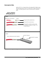
Check the List of
Supplied Items
Verify that you have received the following items with each one of your
3499A/B/C mainframe. If anything is missing, contact your nearest Agilent
Technologies Sales Office.
-----
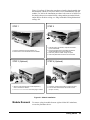
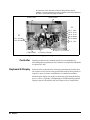
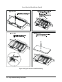
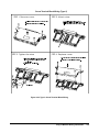
One power cord;
One User’s Manual (if ordered);
One Tie Down Clip 03499-21002 (for Agilent 3499B only);
Any plug-in modules you ordered, which were delivered in separate
shipping containers.
This Service Manual must be ordered separately.
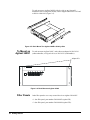
Initial Inspection
The Agilent 3499A/B/C was carefully inspected, both mechanically and
electrically, before shipment. It should be free of any scratches and in perfect
electrical order upon receipt. You should inspect the Unit for any damage
that may have occurred in transit.
WARNING
To avoid potentially hazardous electrical shock, do not perform
electrical tests when there are signs of damage to any portion
of the outer enclosure.
If the shipping container or packing material shows any signs of damage or
stress, you should notify both carrier and the nearest Agilent Technologies
Sales Office.
Getting Started
21
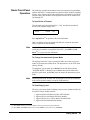
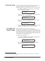
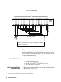
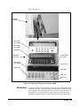
Power on the
Instrument
Make sure no mechanical damages on the instrument, then you can perform
the following procedure to verify that the instrument is in proper working
order.
1. Connect the instrument to an AC power source with the supplied
power cord.
2. Push the Power switch to power on the instrument.
3. On power-up, every segment in the display should light up briefly.
The internal self-test will begin following this “starburst” display.
4. If the self-test passes, the default system mode and the GPIB address
are displayed, together with a “beep” sound. Then the display shows
the instrument model number.
Note
If the instrument failed the self-test, contact your nearest Agilent
Technologies Sales Office.
If the Instrument
Does Not Turn On
Note
1. Verify that the power cord is firmly plugged into the power receptacle
on the rear panel of the instrument.
2. Make sure that the power source the instrument is plugged into is
energized.
3. Verify that the instrument is turned on.
If the instrument DOES NOT turn on after you perform the above
procedure, contact your nearest Agilent Technologies Sales Office.
Module Installation
WARNING
Only qualified personnel should install or remove the plug-in
modules into or from an Agilent 3499A/B/C mainframe. Make
sure to disconnect the power cord from the back of the
mainframe prior to installing or removing any modules.
Caution
Use anti-static procedures when configuring, installing or
removing any plug-in modules. To prevent contamination to the
modules that could degrade performance, handle the modules
by the side edges or shields only. Do not touch the board
surfaces or components.
Module Installation
Upon receipt of an Agilent 3499A/B/C mainframe, the plug-in modules you
ordered were not installed in the mainframe. In addition, the terminal
block(s) and/or the cables ordered for wiring external test circuits are also
separated from your modules.
22
Getting Started
Figure 2-1 on Page 23 shows the procedure to install a plug-in module into
the mainframe 3499B, as well as to attach a screw terminal block onto the
module. For 3499A, the installation procedure is the same as in 3499B. For
the details about screw terminal blocks, crimp-and-insert terminal blocks
and/or DIN-to-D cables wiring, see “Plug-in Modules Wiring Information”
on Page 110.
STEP 1
STEP 2
1. Face the mainframe rear panel towards you;
2. Select a slot in which the module is to be installed.
1. Hold the sides of the module, component side down,
by the metal shields;
2. Insert the module into the slot guides and slide the
module towards the front of the instrument;
3. Push firmly until the module “snaps” into place.
4. Push both plastic levers inward to lock the module.
STEP 3 (Optional)
STEP 4 (Optional)
1. Wire the screw terminal block (module dependent,).
refer to Chapter 8 for details);
2. Attach the screw terminal block onto the plug-in module.
1. Push firmly until the terminal block “snaps” into place;
2. Lock the screw terminal block with the two screws
(Torque < 8 in-lbs).
Figure 2-1. Module installation
Module Removal
To remove a plug-in module from an Agilent 3499A/B/C mainframe,
reverse the procedures above.
Getting Started
23
Operating the Instrument
An Agilent 3499A/B/C Switch/Control System can be easily operated from
the front-panel, or programmed with SCPI (in SCPI mode) or 3488A (in
3488A mode) commands over the remote interface.
The following sections are only intended to show some basic front-panel
operation. For more information about the front panel operation, refer to
Chapter 3 “Front-Panel Operation” starting from Page 31.
Channel
Addressing
In Agilent 3499A/B/C Switch/Control System, a channel refers to an
individual relay on a switching module, or an individual bit/port on a digital
I/O module. The channel address is in the form of snn, where s represents
slot number. Slot 0 refers to the mainframe controller board, s = 1-2 (for an
Agilent 3499B), s = 1-5 (for an Agilent 3499A) or s = 1-9 (for an Agilent
3499C); nn represents channel number (module dependent, see Table 2-1).
Table 2-1. Plug-in Modules Channel Addressing
Channel Addressing
Agilent P/N
(snn, s = Slot Numbera; nn = Channel Number)
Descriptions
SCPI Mode
3488A Mode
Agilent 44470A
10-Channel MUX Module
s00, s01, s02, s03... s08, s09
Same as in SCPI mode.
Agilent 44470D
20-Channel MUX Module
s00, s01, s02, s03... s18, s19
Same as in SCPI mode.
Agilent 44471A
10-Channel GP Relay Module
s00, s01, s02, s03... s08, s09
Same as in SCPI mode.
Agilent 44471D
20-Channel GP Relay Module
s00, s01, s02, s03... s18, s19
Same as in SCPI mode.
Agilent 44472A
Dual 4-Channel VHF Module
Group 0: s00, s01, s02, s03;
Group 1: s10, s11, s12, s13
Same as in SCPI mode.
Agilent 44473A
4 x 4 Matrix Module
Row: 0, 1, 2, 3; Column: 0, 1, 2, 3
(s00, s01, s02, s03; s10, s11, s12, s13;
Same as in SCPI mode.
s20, s21, s22, s23; s30, s31, s32, s33)b
Agilent 44474A
16-Bit Digital I/O Module
Individual Bits: s00, s01, s02... s14, s15
8-Bit Ports: s00, s01
16-Bit Port: s00
Individual Bits: s00, s01, s02... s14, s15
8-Bit Ports: s00, s01
16-Bit Port: s02
Agilent 44475A
Breadboard Module
N/A
N/A
Agilent 44476A
3-Channel 13 GHz Microwave
Switch Module
s00, s01, s02
Same as in SCPI mode.
Agilent 44476B
2-Channel 26 GHz Microwave
Switch Module
s00, s01
Same as in SCPI mode.
Agilent 44477A
7-Channel Form-C Relay Module
s00, s01, s02, s03, s04, s05, s06
Same as in SCPI mode.
24
Getting Started
Table 2-1. Plug-in Modules Channel Addressing
Channel Addressing
Agilent P/N
(snn, s = Slot Number a; nn = Channel Number)
Descriptions
SCPI Mode
Agilent 44478A/B
50/75 W 1.3 GHz MUX Module
Group 0: s00, s01, s02, s03
Group 1: s10, s11, s12, s13
Agilent N2260A
1-Wire Mode: s00, s01... s78, s79d
2-Wire Mode: s00, s01...s38, s39
Dual 2-Wire Mode: s00, s01...s38, s39
40-Channel MUX Modulec
3488A Mode
Same as in SCPI mode.
s00, s01...s38, s39f
4-Wire Mode: s00, s01...s18, s19e
Agilent N2261A
40-Channel GP Relay Module
Agilent N2262A
4X8 Matrix Module
Agilent N2263A
32-Bit Digital I/O Module
Agilent N2264A
12-Channel GP Relay +
3-Channel High-current GP Relay +
16-Bit Digital I/O Module
Agilent N2265A
4X4 Matrix +
16-Bit Digital I/O Module
s00, s01, s02, s03... s37, s38, s39
Same as in SCPI mode.
Row 0, 1, 2, 3; Column 0, 1, 2, 3... 6, 7
(s00, s01, s02... s07; s10, s11, s12... s17;
s20, s21, s22... s27; s30, s31, s32... s37)
Same as in SCPI mode.
Individual Bits: s00, s01, s02... s30, s31;
8-Bit Ports: s00, s01, s02, s03;
16-Bit Ports: s00, s02;
32-Bit Port: s00.
Individual Bits: s00, s01, s02... s30, s31;
8-Bit Ports: s00, s01, s02, s03;
16-Bit Ports: s04, s05;
32-Bit Port: s06.
12 GP Relays: s00, s01, s02... s10, s11;
3 High-current GP Relays: s20, s21, s22;
12 GP Relays: s00, s01, s02... s10, s11;
3 High-current GP Relays: s20, s21, s22;
16-Bit Digital I/O:
Individual Bits: s30, s31, s32... s44, s45;
8-Bit Ports: s30, s31;
16-Bit Port: s30.
16-Bit Digital I/O:
Individual Bits: s30, s31, s32... s44, s45;
8-Bit Ports: s30, s31;
16-Bit Port: s32.
4X4 Matrix: Row 0, 1, 2, 3; Column 0, 1, 2, 3
4X4 Matrix: Same as in SCPI mode.
(s00, s01, s02, s03; s10, s11, s12, s13;
s20, s21, s22, s23; s30, s31, s32, s33)
16-Bit Digital I/O:
Individual Bits: s40, s41, s42... s54, s55;
8-Bit Ports: s40, s41;
16-Bit Port: s40.
16-Bit Digital I/O:
Individual Bits: s40, s41, s42... s54, s55;
8-Bit Ports: s40, s41;
16-Bit Port: s42.
Agilent N2266A
40-Channel MUX Module
1-Wire Mode: s00, s01... s78, s79
2-Wire Mode: s00, s01...s38, s39
Dual 2-Wire Mode: s00, s01...s38, s39
4-Wire Mode: s00, s01...s18, s19
s00, s01...s38, s39
Agilent N2267A
8-Channel High Current GP Module
s00, s01,..., s06, s07
s00, s01,..., s06, s07
Agilent N2268A
50W 3.5GHz Dual 1-to-4 MUX
Module
Group 0: s00, s01, s02, s03
Group 1: s10, s11, s12, s13
Same as in SCPI mode.
Getting Started
25
Table 2-1. Plug-in Modules Channel Addressing
Channel Addressing
Agilent P/N
(snn, s = Slot Numbera; nn = Channel Number)
Descriptions
SCPI Mode
3488A Mode
Agilent N2269A
Multifunction Module
16-Bit D/A Port:
s40, s42
16-Bit Memory Access Port:
S50
Digital I/O:
individual Bits: s00, s01,..., s30, s31
8-Bit Port: s00, s01, s02, s03
16-Bit Port: s00, s02
16-Bit D/A Port:
s44, s45
16-Bit Memory Access Port:
S58
Digital I/O:
individual Bits: s00, s01,..., s30, s31
8-Bit Port: s00, s01, s02, s03
16-Bit Port: s04, s05
Agilent N2270A
10-Channel High Voltage MUX
Module
s00, s01,..., s08, s09
s00, s01,..., s08, s09
Agilent N2272A
1GHz RF 1-to-9 MUX Module
s00, s01,..., s07, s08
Not supported.
Agilent N2276A/B
Dual 1-to-6(4) Microwave
MUX/Atttenuator Module
Two 1-to-4(6) Microwave Switch:
s00, s01, s02, s03(, s04, s05);
s10, s11, s12, s13(, s14, s15).
Two Attenuator:
s20; s30.
Not supported.
Agilent N2280A
Quadruple 1-to-2 Optical Switch
Module
Group0: s00, s01
Group1: s10, s11
Group2: s20, s21
Group3: s30, s31
Group0: s00, s01
Group1: s10, s11
Group2: s20, s21
Group3: s30, s31
Agilent N2281A
Dual 1-to-4 Optical Switch Module
Group0: s00, s01, s02, s03
Group1: s10, s11, s12, s13
Group0: s00, s01, s02, s03
Group1: s10, s11, s12, s13
Agilent N2282A
1-to-8 Optical Switch MUX Module
s00, s01, s02... s07.
Not supported.
4-Bit Built-in Digital I/O
Individual Bits: 091, 092, 093, 094;
4-Bit Port: 090.
Same as in SCPI mode.
a.
For an Agilent 3499A, the Slot Number = 1-5; for an Agilent 3499B, the Slot Number = 1-2; for an Agilent 3499C, the Slot Number
= 1-9.
b. A channel number on a matrix module is formed in Slot-Row-Column format, i.e., channel address s23 means row 2, column 3 in
Slot s.
c. Agilent N2260A can be used as an 80-channel 1-wire MUX module, a 40-channel 2-wire MUX module, two 20-channel 2-wire
MUX modules, or a 20-channel 4-wire MUX module in SCPI mode.
d. The Low (L) terminals of the 40 2-wire channels form the first 40 1-wire channels (Channels 00-39), and the High (H) terminals of
the 40 2-wire channels form the second 40 1-wire channels (Channels 40-79).
e. The first channels (CH00 & CH20) of either banks (BANK 0 and BANK 1) form Channel 00, the second channels (CH01 & CH21)
of either banks form Channel 01, and so on.
f. In 3488A mode, Agilent N2260A is used as a 40-channel 2-wire MUX module.
26
Getting Started
Basic Front-Panel
Operation
The following examples demonstrate some basic operation to operated the
Agilent 3499A/B/C. Assuming that an Agilent N2260A module is installed
in slot 1 of the Agilent 3499A and configured as a 40-channel 2-wire MUX
(default setting), the channels on the Agilent N2260A can be addressed as
100 through 139.
To Open/Close a Channel
Turn the knob to the desired channel (i.e. 102), the channel specified is
shown on the channel display area.
MUX
OPEN
102
Press Open/Close[1] to open/close the selected channel.
Only one channel can be opened/closed each time, repeat the procedure
above to open/close other channels.
Note
To open all channels on a module, press Card Reset. To open all channels
on the plug-in modules in an Agilent 3499A/B/C, press Shift + Card
Reset[2], or cycle power the instrument.
To Change the Instrument System Mode
The Agilent 3499A/B/C can be operated in either one of the two system
modes: SCPI mode and 3488A mode. The instrument is set to SCPI mode
(factory default).
To change the system mode, press Menu first, turn the knob until the
“SYSTEM MODE” is displayed, press Enter; then turn the knob to the
specific system mode, press Enter again to change the instrument system
mode.
Note
Switching between SCPI mode and 3488A mode will reset the instrument
to the factory default settings (except the GPIB address).
To View Relay Cycles
The relay cycle counts for the switching relays on some Agilent modules can
be read out. These modules include:
1.
2.
3.
4.
Agilent N2260A 40-Channel 2-Wire MUX Module;
Agilent N2261A 40-Channel GP Relay Module;
Agilent N2262A 4 x 8 2-Wire Matrix Switch Module;
Agilent N2264A Multifunction Module;
[1]. Press Close means to press the key Close on the front panel of the Agilent 3499A/B/C.
[2]. Press Shift + Card Reset means to press the key Shift first, then press the key Card Reset.
Getting Started
27
5. Agilent N2265A Multifunction Module;
6. Agilent N2266A 40-channel 2-Wire MUX Module;
7. Agilent N2267A 8-channel High Current GP Module;
8. Agilent N2268A 50Ω 3.0GHz Dual 1-to-4 MUX Module;
9. Agilent N2270A 10-Channel High Voltage MUX Module;
10.Agilent N2272A 1GHz RF 1-to-9 MUX Module;
11. Agilent N2276A/B Dual 1-to-6(4) Microwave MUX/Atttenuator
Module (not include Attenuators);
12.Agilent N2280A/81A/82A Optical Switch Modules.
To read out the relay cycles, press View, turn the knob until the “RELAY
CYCLES” is displayed, press Enter to view the relay cycles of the
switching relays. Turn the knob to view all the relay cycles on the plug-in
modules.
Note
“N/A” will be displayed a little while if the module does not support relay
cycle count feature.
To View the Errors
The Agilent 3499A/B/C can store up to 10 errors in the error queue. Once
an error occurs, the ERROR annunciator turns on.
To view the errors, press View, turn the knob until “ERROR” is displayed,
press Enter to view the error. Refer to Appendix B “Error Messages”
starting from Page 122 for more error messages.
Note
In SCPI mode, the instrument will display “NO ERROR” for a little while,
then return to the upper menu if the error queue is empty. In 3488A mode,
the instrument will display “0000” if no error occurs.
To Rack Mount the Agilent 3499A/B/C
You can mount the Agilent 3499A/B/C mainframes on a standard 19-inch
rack cabinet with the optional rack-mounting kits. The instructions and
mounting hardware are included with each rack-mounting kit.
28
Getting Started
To Mount an
Agilent 3499A
To rack mount an Agilent 3499A, the full-rack-width mainframe, order either:
• Rack-mount kit with handles, part number 5183-7170, or
• Rack-mount kit without handles, part number 5183-7171.
Figure 2-2. Rack Mount an Agilent 3499A
To Mount an
Agilent 3499B
To rack mount a single Agilent 3499B, the half-rack-width mainframe,
order an adapter kit 5183-7172 (Figure 2-3). This kit includes the flange and
filler panel.
Figure 2-3. Rack Mount a Single Agilent 3499B with Adapter Kit 5183-7172
Or, you can order a Support Shelf 5063-9255, a slide kit 1494-0015, and a
filler panel 5002-3999 (Figure 2-4).
Figure 2-4. Rack Mount a Single Agilent 3499B on a Support Shelf
Getting Started
29
To rack mount two Agilent 3499B’s side-by-side (or any System II
instrument next to an Agilent 3499B), order a Support Shelf 5063-9255 and
a slide kit 1494-0015 (Figure 2-5).
Figure 2-5. Rack Mount Two Agilent 3499B’s Side-by-Side
To Mount an
Agilent 3499C
To rack mount an Agilent 3499C, order either an adapter kit 5063-9216
(without handles, see Figure below) or 5063-9223 (with handles).
Adapter Kit
Figure 2-6. Rack Mount an Agilent 3499C
Filler Panels
Order filler panels to cover any unused slots in an Agilent 3499A/B/C.
• 1-slot filler panel, part number 03499-00023 (option FP1)
• 2-slot filler panel, part number 03499-00024 (option FP2).
30
Getting Started
Chapter 3
Front-Panel Operation
About This Chapter
This chapter introduces you to each front-panel menu, it covers all aspects
of front-panel operation. Chapter contents include:
• Front-Panel Overview . . . . . . . . . . . . . . . . . . . . . . . . . . . . . .
• Local/Remote Control . . . . . . . . . . . . . . . . . . . . . . . . . . . . .
• To Monitor a Channel or a Slot. . . . . . . . . . . . . . . . . . . . . . .
• To Close or Open a Channel . . . . . . . . . . . . . . . . . . . . . . . . .
• To Read from a Digital I/O Port . . . . . . . . . . . . . . . . . . . . . .
• To Write to a Digital I/O Port . . . . . . . . . . . . . . . . . . . . . . . .
• To Store an Instrument State . . . . . . . . . . . . . . . . . . . . . . . . .
• To Recall an Instrument State . . . . . . . . . . . . . . . . . . . . . . . .
• View Key Operation . . . . . . . . . . . . . . . . . . . . . . . . . . . . . . .
• Mode Key Operation. . . . . . . . . . . . . . . . . . . . . . . . . . . . . . .
• Scanning Operation. . . . . . . . . . . . . . . . . . . . . . . . . . . . . . . .
• Menu Key Operation. . . . . . . . . . . . . . . . . . . . . . . . . . . . . . .
• To Reset a Module . . . . . . . . . . . . . . . . . . . . . . . . . . . . . . . .
• To Reset the Instrument . . . . . . . . . . . . . . . . . . . . . . . . . . . .
Page 32
Page 34
Page 34
Page 36
Page 36
Page 36
Page 37
Page 38
Page 38
Page 40
Page 43
Page 48
Page 57
Page 57
The following conventions are used for the front-panel operation.
n
The keys on the front-panel keyboard are expressed in bold font
and normally associated with a “press”. For example, press Mon.
n
The front panel display annunciators are expressed in bold font
followed by an “annunciator”. For example, MON annunciator.
n
The information shown on the front panel display is enclosed
within a pair of quotation marks.
n
Shift + Recall[1] indicates the sequential operation: first press
Shift, then press Recall.
Note
If no key is pressed within 5 seconds or an invalid key is pressed after the
key Shift has been pressed, the SHIFT annunciator will turn off.
Note
During a menu operation, if no key is pressed within 30 seconds or an
invalid key is pressed, the instrument will exit the operation.
[1]. Also applicable to keys Card Reset, Scan, and S.List.
Front-Panel Operation
31
Front-Panel Overview
The Agilent 3499A/B/C can be operated in either SCPI mode or 3488A
mode. All the operations demonstrated in this chapter apply to both modes,
unless specifically indicated.
%
6:,7&+&21752/6<67(0
5HVHW
&DUG
5HVHW
6WRUH
5HFDOO
/RFDO
6KLIW
3RZHU
6WRS
6FDQ
0RQ
6WHS
&OHDU
6/LVW
9LHZ
0RGH
2SHQ
5HDG
&ORVH
:ULWH
0HQX
(QWHU
Note: 1. The keys
with 10 , 11 , 14 , and 15 guide you through menus to configure various parameters of the instrument.
The details on these menus operation are demonstrated later in this chapter.
2. The keys
1.
2.
3.
4.
5.
6.
7.
8.
9.
10.
11.
12.
13.
with 2 , 3 , 4 , 12 and 14 are double-function keys. See the next page for the rules of their operation.
Power on/standby
a. Reset a module
b. Reset instrument
Shift/Local key
a. Recall instrument state
b. Store instrument state
Monitor a channel/port/module
Open relay channel
Close relay channel
Read from DIO port
Write to DIO port
Enable View menu to:
View errors
View scan list
View relay cycle counts
Enable Mode menu to:
Configure MUX module
Configure DIO module
a. Initiate scan
b. Stop scan
Step through scan list
14. a. Enable S.List menu to:
Create scan list
Select arm source
Select arm count
Select trigger source
Set channel delay time
b. Clear scan list
15. Enable Menu menu to:
Pair two modules together
Enable/disable trigger out pulse
Set instrument power-on state
Configure GPIB/RS-232 interface
Perform self-test
Select SCPI/3488A mode
Query firmware revision
Query serial number
16. Confirm the selection
17. Left arrow key
18. Right arrow key
19. Knob
Figure 3-1. Agilent 3499B Front Panel
32
Front-Panel Operation
Display
%
6:,7&+&21752/6<67(0
. . . . . . . . . . . .
,. ,. ,. ,. ,. ,. ,. ,. ,. ,. ,. ,.
As shown in above figure, the display is divided into three areas. Channel
area displays the channel/port/slot number. The main display area displays
the channel status (open/closed), or other information messages. Around the
main display area are the annunciators, as listed in Table 3-1.
Table 3-1. Annunciators Summary
Annunciator
SCAN
Scan is initiated.
MON
Instrument is in monitor mode.
VIEW
Scan list, errors or relay cycle counts are being viewed.
CONFIG
*
ADRS
RMT
ERROR
EXT
SHIFT
Channel
Addressing
Channel/Slot
Selection
Indication
Any configuration key has been pressed.
Instrument is advancing a scan step.
Instrument is addressed to listen or talk over the remote interface.
Instrument is in remote mode.
Error queue is not empty.
Scan is waiting for external trigger source.
Shift key has been pressed.
Many of the front-panel operations require you specify one or more
channels. A channel refers to an individual relay on a switching module, or
an individual bit/port on a digital I/O module. The channel address is in the
form of snn, where s is the Slot Number (1-5 for an Agilent 3499A, 1-2 for
an Agilent 3499B, 1-9 for an Agilent 3499C and Slot 0 reserves for the 4-bit
built-in digital I/O), and nn represents channel number on the plug-in
modules (module dependent). Refer to Table 2-1 on Page 24 for more details
about the channel addressing.
The two arrow keys (<= and =>) together with the knob are used to select
slots and channels. The following procedure shows you how to do that.
Front-Panel Operation
33
1. Select a slot. Press the two arrow keys to select a desired slot directly,
or turn the knob to select the desired slot number.
N2260A
1
2. Select a channel. Turn the knob to select a channel (3 digital
number). As shown below, the top display indicates the current
channel 101 is a MUX channel and in OPEN state, and the lower
indicates that the current bit 401 is a digital input port.
MUX
DIN
Note
OPEN
101
401
Open, Close, Read and Write keys are invalid if a slot, instead of a
channel, is selected.
To demonstrate the following operations more easily and clearly, we assume
five modules have been installed in an Agilent 3499A mainframe. The
configuration is:
Slot 1
Agilent N2260A MUX module
Slot 2
Agilent N2261A GP Relay module
Slot 3
Agilent N2262A Matrix module
Slot 4
Agilent N2263A Digital I/O module
Slot 5
Agilent N2260A MUX module
Local/Remote Control
When power-up, the instrument is in local mode. All keys on the front panel
are fully functional. When receiving any command from the remote
interface, the instrument automatically switches to remote mode (ADRS and
RMT annunciators light up), all front-panel keys are locked, except the keys
Local, Mon, View, Enter, the two arrow keys and the knob.
Local and Shift use the same key. While in local mode, it is used as Shift
key. While in remote mode (the RMT annunciator turns on), it is used as
Local key.
To Monitor a Channel or a Slot
In a switch/control system, it is necessary to acquire, confirm and
continuously monitor the current status of a particular switching channel, a
34
Front-Panel Operation
digital I/O port, or an entire plug-in module. Agilent 3499A/B/C provides
you the ability to achieve the above.
1.
2.
3.
4.
Press Mon, the MON annunciator lights up;
Select the slot or the channel/port to be monitored;
Press Enter to display the next part if necessary;
Press Mon again to exit the monitoring state, the MON annunciator
turns off.
Table 3-2. Display on Monitoring Mode
Display
Description
1:0, , , , , ,6, , ,9,
2
ROW 3: ,1, ,3, , ,6,7
3
0; , ,3,COL 3,
3
00:H255
4
DIO
DOUT
L254.
12
090
0
091
ROW 0: ,1, ,3,
5
00:H255
5
L254.
The display for a multiplexer or a GP relay module. This display indicates that
the monitored module is in Slot 2 and channels 10, 16, and 19 are closed.
The display for a matrix module. The top is the row information, indicating that
the relays on Row 3, Columns 1, 3, 6 and 7 of the module (in Slot 3) are
closed. The lower display is the column information, indicating that relays on
column 3, row 0 and 3 are closed.
The display for a digital I/O module. The first 2 digits on the left (“00” in this
case) represents the “L” 8-bit port address. Adding one to this value, the “H”
8-bit port address is obtained. Data with a trailing decimal point indicates that
the last operation on that port was a WRITE, data without a trailing decimal
point indicates that the last operation on that port was a READ. This display
shows that the data last read from Port 401 is 255 and the data last written to
Port 400 is 254.
The top display is for the built-in digital I/O Port 090 and the data from the last
operation.
The lower display indicates that data last written to the bit channel 091 is 0.
For a multifunction module, the first function on the module is displayed, then
the next. This display is an example of a multifunction module with matrix and
DIO functions.
Note
The built-in digital I/O can be monitored either as individual bit channels
(091-094) or as a 4-bit port (090).
Note
For MUX modules and GP Relay modules, 10 channels can be displayed at
one time; for matrix modules, one ROW or one Column can be displayed at
one time; for digital I/O modules, two 8-bit ports can be displayed at one
time. For multifunction modules, the first function on the module is
displayed, then the next.
Front-Panel Operation
35
To Close or Open a Channel
To close/open a channel, you need to:
1. Select the channel to be closed or opened;
2. Press Close/Open to close/open the channel.
Repeat steps 1 & 2 to close or open other channels.
To Read from a Digital I/O Port
To read data from the built-in digital I/O port/bits (090-094), or any one of
the 8-bit ports on a digital I/O, you need to:
1. Select a digital I/O port;
2. Press Read to read data from the selected port.
For example, the display below shows the data read from Port 401.
Note
DIN
255 401
DIN
11111111 401
Decimal format
Binary format
Data display format of individual 8-bit ports can be specified either in
binary or decimal. Once specified, the format applies to all input and output
operations on the same port (refer to “Mode Key Operation” on Page 40).
To Write to a Digital I/O Port
To write data to the built-in digital I/O port/bits (090-094), or any one of the
8-bit ports on a digital I/O, you need to:
1. Select a digital I/O port to be written to (“DIN” indicates that the last
operation on the port is a READ, and “DOUT”, a WRITE);
DIN
401
2. Press Write, the data from the last operation (READ or WRITE) on
the selected port will be displayed and “DOUT” is displayed to
indicate the port is now an output port;
DOUT
36
Front-Panel Operation
255 401
3. Edit the value. Press the two arrow keys to select the to-be-edited bit
(in dim), turn the knob to modify the value;
DOUT
254 401
4. Press Enter to output the data to the selected port, or press Write
again to cancel the current write operation.
To Store an Instrument State
The Controller board in Agilent 3499A/B mainframe has two types:
Controller board Version 1.0 and Version 2.0. Agilent 3499C always has a
Controller board of Version 2.0.
Firmware of Agilent 3499A/B/C mainframe currently has 4 revisions: REV
1.0, REV 2.0, REV 3.0 and REV 4.0. Firmware REV 1.0/2.0/3.0 runs under
Controller board Version 1.0 and REV 4.0 runs under Controller board
Version 2.0.
The current instrument setup can be stored for future convenience. The
stored setups can be recalled directly, or included in a scan list. However, the
stored instrument setup in SCPI mode is different from that in 3488A mode.
Table 3-3 lists these differences.
Table 3-3. The Differences Between Two Modes
SCPI Mode
3488A Mode
Stored information:
1. Status of relay channels (open/close);
2. Status of digital I/O ports (input/output) on digital I/O
modules in either static Mode #1 or Mode #2;
3. Module configurations: card pair, 1/2/4-wire function
mode, baud rate, flow control, etc.;
4. Scanning setups: scan list, arm count, arm source, etc.
Stored information:
1. Status of relay channels (open/close);
2. Status of digital I/O ports (input/output) on digital I/O
modules in either static mode1 or mode2.
For Firmware REV 4.0: Up to 50 instrument setups can be
stored (numbered 1-50);
For Firmware REV 1.0/2.0/3.0: Up to 10 instrument setups
can be stored (numbered 1-10).
Up to 40 instrument states can be stored (numbered 1-40).
To store a instrument setup:
1. Press Shift + Recall, the display would be:
STORE 01
2. Turn the knob to change the memory location number (i.e. 05);
STORE 05
3. Press Enter to store the current instrument setup (to location 5).
Front-Panel Operation
37
Note
An instrument reset does not affect the stored instrument setup information.
Once a setup is stored, it remains until overwritten or specially deleted with
a SCPI command SYSTem:STATe:DELete.
Note
All the stored instrument setups will be cleared automatically whenever the
system mode is changed.
To Recall an Instrument State
A previously stored instrument setup can be recalled. Before recalling a
stored setup, the instrument verifies that all module type and slot assignment
match the setup. If a mismatch is detected, the recall operation will stop and
a string “RECALL FAILED” will be returned (no error occurs).
To recall an instrument setup:
1. Press Recall, turn the knob to a previously stored setup (i.e. 05);
RECALL 05
2. Press Enter to recall the setup (i.e. 05); press Recall again to cancel
the current recall operation.
View Key Operation
The instrument can store up to 10 errors[1] in the error queue, up to 200
channels in the scan list, as well as the relay cycle counts on the newer
plug-in modules. The View key provides you an intuitive way to query these
information. Table 3-4 lists the View key structure.
Table 3-4. View Key Structure
1st level Items
To View an Error
Description
ERROR
Query the errors recorded in the error queue.
SCAN LIST
Query the channels included in the scan list.
RELAY CYCLES
Query the relay cycle counts on some modules.
To view an error:
1. Press View (the VIEW annunciator turns on), turn the knob to
“ERROR”, then press Enter;
2. If no error is in the error queue (the ERROR annunciator is off), the
instrument displays “NO ERROR”, and then returns to the first level
[1]. In 3488A mode, only the sum of the values of the possible error conditions, as defined in Table 6-20 on Page 128, is
recorded in the error queue and shown on the front panel.
38
Front-Panel Operation
of the View menu automatically.
NO ERROR
108
If there are errors (the ERROR annunciator is on), the first error in
the error queue is displayed. Press the arrow key to scroll the display
to show the whole error message;
01:ERR -109
MISSING PARAMETER
3. Turn the knob to view other errors in the error queue, or press Enter
to return to the first level of the View menu, the ERROR annunciator
turns off;
4. Press View again to exit the View menu operation, the VIEW
annunciator turns off.
Note
To View a Scan List
All errors are cleared once the error queue is viewed, and the ERROR
annunciator turns off. Refer to Appendix B starting from Page 122 for
details about the instrument errors.
To view the channels included in a scan list (assuming channels 103-107 are
included in the scan list):
1. Press View (VIEW annunciator lights up). Turn the knob until
“SCAN LIST” is displayed, then press Enter;
SCAN LIST
101
2. The first channel in the scan list is displayed on the channel area.
Continuously turn the knob to view other channels in the scan list;
001 OF 005
103
3. Press Enter to return to the first level of the View menu;
SCAN LIST
107
4. Press View again to end this operation, the VIEW annunciator turns off.
Front-Panel Operation
39
To View the Relay
Cycles
To view the relay cycle counts:
1. Press View, the VIEW annunciator lights up. Turn the knob until
“RELAY CYCLES” is displayed, then press Enter;
RELAY CYCLES
400
2. If no module with the relay cycle count feature[1] is present, “N/A”
will be displayed, then the display automatically returns to the first
level of the View menu;
N/A
400
If the selected channel is a relay without the cycle counts feature, the
instrument will display the cycle counts of the first relay with the feature;
7383
100
If the selected channel (i.e. 109) is a relay with the cycle counts
feature, the cycle counts of the relay will be displayed;
10132
109
3. Turn the knob to read other relays cycle counts, or press Enter to
return to the first level of the View menu;
RELAY CYCLES
108
4. Press View again to exit the View menu operation, the VIEW
annunciator turns off.
Mode Key Operation
A digital I/O and the digital I/O ports can be configured from the instrument
front panel. In SCPI mode, Agilent N2260A can be configured as different
MUX modules. The Mode key is designed for these configurations.
• Agilent N2260A can be configured in SCPI mode. Table 3-5 shows the
Mode key structure in this case.
[1]. Relay cycle count feature is supported by the switching relays on the Agilent N2260A/61A/62A/64A/65A modules.
40
Front-Panel Operation
Table 3-5. Agilent N2260A Configuration (Mode)
1st level Items
2nd Level Items
Description
WIRE1
WIRE2
WIRE4
DUAL WIRE2
CONFIG MUX
Configure Agilent N2260A Multiplexer module to work as: 80-channel
1-wire, 40-channel 2-wire, 20-channel 4-wire, or two independent
groups of 20-channel 2-wire module.
• The digital I/O modules can be configured in either SCPI mode or
3488A mode. Table 3-6 on Page 41 shows the Mode key structure.
Note
The 4-bit built-in digital I/O in Slot 0 cannot be configured.
• The Mode key shows a completely different structure (Table 3-7)
when it is used to configure a digital I/O port.
Table 3-6. Digital I/O Configuration (Mode)
1st level
Items
CONFIG DIO
2nd Level
Items
MODE 1
MODE 2
MODE 3
MODE 4
MODE 5
3rd Level
Items
CONT POL POS
CONT POL NEG
4th Level
Items
FLAG POL POS
FLAG POL NEG
5th Level
Items
I/O POL POS
I/O POL NEG
Description
Configure DIO module, including
the handshake mode, the
control line and flag line
polarities, and the polarity of the
I/O direction line.
Table 3-7. Digital I/O Port Configuration (Mode)
1st Level Items
2nd Level Items
Description
DATA POLARITY
POS POLARITY
NEG POLARITY
Set the polarity of the data lines for the port.
DISP FORMAT
DECIMAL
BINARY
Set data display format for the port.
Agilent N2260A
Configuration
To configure an Agilent N2260A MUX module:
1. Select a slot in which an Agilent N2260A module is installed;
N2260A
1
2. Press Mode, the CONFIG annunciator lights up and “CONFIG
MUX” is displayed;
CONFIG MUX
1
Front-Panel Operation
41
3. Press Enter, turn the knob to select one mode (i.e. WIRE1);
WIRE1
1
4. Press Enter to return to “CONFIG MUX”, press Mode again to exit
the configuration, the CONFIG annunciator turns off accordingly.
DIO Module
Configuration
A digital I/O module can be configured, which include the flow control
mode, the control line polarity, the flag line polarity, and the I/O direction
line polarity.
To configure a digital I/O module:
1. Select a slot in which a digital I/O is installed;
N2263A
4
2. Press Mode, the CONFIG annunciator lights up and “CONFIG DIO”
is displayed, then press Enter;
CONFIG DIO
4
3. Turn the knob to select the flow control mode (i.e. MODE 2),
then press Enter;
MODE 2
4
4. Turn the knob to select the control line polarity (i.e. CONT POL
POS), then press Enter;
CONT POL POS
4
5. Turn the knob to select the flag line polarity (i.e. FLAG POL POS),
then press Enter;
FLAG POL POS
4
6. Turn the knob to select the I/O line polarity (i.e. I/O POL POS),
then press Enter;
I/O
42
Front-Panel Operation
POL POS
4
7. The instrument returns to “CONFIG DIO”, press Mode again to exit
the configuration, the CONFIG annunciator turns off accordingly.
DIO Port
Configuration
To configure the data line polarity and data display format for an individual
digital I/O port:
1. Select a digital I/O port (i.e. Port 401), press Mode (the CONFIG
annunciator lights up). Turn the knob to select one item (i.e. DATA
POLARITY);
DATA POLARITY
401
2. Press Enter, turn the knob to select the polarity (i.e. NEG
POLARITY);
NEG POLARITY
401
3. If another item “DISP FORMAT” is selected, press Enter, then turn
the knob to select the data display format (i.e. BINARY);
BINARY
401
4. Press Enter to select the data display format and return to “DISP
FORMAT”, press Mode again to exit the configuration, the CONFIG
annunciator turns off accordingly.
To configure other digital I/O ports, repeat Steps 1 through 4.
Note
Once you have selected the data display format for a port, it applies to all
input and output operations on that port.
Scanning Operation
The scan operation in SCPI mode is different from that in 3488A mode. In
3488A mode, you only need to create a scan list, then step through the scan
list by repeatedly pressing Step. However, scanning in SCPI mode has more
features (refer to Figure 3-2).
Front-Panel Operation
43
Stop key
Idle
Idle
Scan key
no
yes
Controlled by
Arm Source
Arm Layer
Another
Scan?
Controlled by
Arm Count
Arm Event
Detection
no
Another
Channel?
yes
Controlled by
Trigger Source
Controlled by
Scan List
Trigger Event
Detection
Trigger Layer
Output Trigger*
Scan Channel
* Note: The trigger out pulse will occur at the specified trig-out line
only if you have configured to enable the slot to output.
Figure 3-2. The Process of Scanning Operation (in SCPI mode)
Overview
Before initiating a scan, a scan list must be set up. You can also specify an
arm source, a trigger source, and the number of sweeps (a sweep is one pass
through the scan list) to control the scan process. All these can be done from
the S.List key. The S.List key structure in SCPI mode (Table 3-8) is
different from that in 3488A mode (Table 3-9 on Page 45).
Table 3-8. S.List Key Structure in SCPI Mode
1st Level
Items
2nd Level
Items
3rd Level
Items
4th Level
Items
Create a scan list to include all the desired
switch channels, DIO bit channels, and/or
the previously stored setups.
ADD TO SCAN
SELECT nnn
CONFIG SCAN
ARM: TIMER
ARM: IMM
ARM: BUS
ARM: EXT
ARM: MIX
ARM: HOLD
COUNT: 00001
SET ALL
nnnnn.nnn SECS
SET CH
SELECT nnn
TRIG: TIMER
TRIG: IMM
TRIG: BUS
TRIG: EXT
TRIG: MIX
TRIG: HOLD
DELAY TIME
44
Front-Panel Operation
Description
nnnnn.nnn SECS
Configure the scan operation, such as an
arm source, an arm count, and a trigger
source.
Set delay time for all channels or for
individual channels.
Table 3-9. S.List Key Structure in 3488A Mode
1st Level Items
2nd Level Items
ADD TO SCAN
SELECT nnn
DELAY TIME
nnnnn.nnn SECS
To Create a Scan
List
Description
Create a scan list to include all the desired
switch channels, DIO bit channels, and/or the
previously stored setups.
Set a delay time for all scanned channels.
To create a scan list, you can:
1. Press S.List, the CONFIG annunciator lights up, and “ADD TO
SCAN” is displayed;
ADD TO SCAN
101
2. Press Enter, then turn the knob to select a previously stored channel
setup (i.e. 001). Press Enter to add it into the scan list;
SELECT
*
001
3. To add other switch channels, digital I/O bits, and/or other stored
channel setups, repeat Step 2;
4. Press S.List again to return to “ADD TO SCAN”, press S.List once
more to exit this operation, the CONFIG annunciator turns off
accordingly.
Note
To Configure a Scan
To view a scan list, press View. To clear a scan list, press Shift + S.List.
The Arm Source, Arm Count and the Trigger Source can be set to configure
a scan:
1. Press S.List, the CONFIG annunciator lights up. Turn the knob until
“CONFIG SCAN” is displayed, then press Enter;
CONFIG SCAN
2. Turn the knob to set the arm source, then press Enter;
ARM: BUS
If “ARM:TIMER” is specified, the instrument will guide you to set
the time interval (default is 0) after pressing Enter. Use the two arrow
keys and the knob to edit or modify the value. Press Enter to set this
Front-Panel Operation
45
value (ranging from 0 to 99999.999 seconds);
00002.000 SECS
3. Use the arrow keys and the knob to set the arm source, press Enter;
COUNT: 00003
4. Turn the knob to set the trigger source, then press Enter to return to
“CONFIG TO SCAN”;
TRIG: MIX
If “TRIG:TIMER” is specified, the instrument will guide you to set
the time interval (default is 0) after pressing Enter. Use the two arrow
keys and the knob to edit or modify the value. Press Enter to set this
value (ranging from 0 to 99999.999 seconds) and return to “CONFIG
TO SCAN”;
00000.200 SECS
5. Press S.List again to exit this operation, the CONFIG annunciator
turns off accordingly.
To Set a Delay Time
1. Press S.List, the CONFIG annunciator lights up. Turn the knob until
“DELAY TIME” is displayed, press Enter;
DELAY TIME
2. To set a uniform delay time for all channels, select “SET ALL”, then
press Enter. Use the arrow keys and the knob to modify the value
(between 0 and 99999.999 seconds). Press Enter to set the delay time
and return to “DELAY TIME”;
SET ALL
00000.002 SECS
DELAY TIME
3. To set a different delay time for individual channel, select “SET CH”,
then press Enter. Turn the knob to select the channel to be set (i.e.
103), then press Enter again and use the arrow keys and the knob to
46
Front-Panel Operation
set its delay time (between 0 and 99999.999 seconds). Press Enter
once more to set the delay time and return to “SET CH” item;
SET CH
107
SELECT CH
103
00000.005 SECS
103
SELECT CH
103
DELAY TIME
103
4. To set a delay time for other channel, repeat the procedure above.
Press S.List again to return to “DELAY TIME”;
5. Press S.List once more to exit this operation, the CONFIG
annunciator turns off accordingly.
To Start a Scan
To start a scan[1]:
1. Press Scan, the SCAN annunciator lights up;
2. Then the instrument will continue scanning according to the
configuration. The arm source is used to control the onset of each
scan sweep. The trigger source is used to advance one channel in the
scan list (open the previous channel and close the next channel in the
list, the * annunciator lights up);
3. When the scanning is finished, the instrument returns to the idle state
and the SCAN annunciator turns off. To stop the scanning in progress
press Shift + Scan.
Note
Once a scan list exists, simply press Step repeatedly to step through the
scan list. In this case, the SCAN and the * annunciators turn off.
Note
Card Pair is functional during a scan, which means that both the channels
included in the scan list and the paired channels will be scanned.
[1]. The scan cannot be performed and “CANNOT INIT” will be displayed if any of the following conditions occurs:
a. The scan list contains a non-existing channel, such as N2260A module changes from WIRE1 to WIRE2.
b. The scan list contains a channel on a digital I/O module that does not work in Mode #1 or Mode #2.
c. A stored channel setup in the scan list does not match the current hardware configuration.
Front-Panel Operation
47
Menu Key Operation
Configuring system-related instrument parameters can be done from the
Menu key. However, the Menu key structure in 3488A mode (Table 3-10)
is different from that in SCPI mode (Table 3-11 on Page 49). Since SCPI
mode can do whatever 3488A mode can, only the Menu key operation in
SCPI mode will be demonstrated.
Table 3-10. Menu Key Structure in 3488A Mode
1st Level Items
2nd Level
Items
3rd Level
Items
4th Level
Items
Description
FIRST SLOT 1
SECOND SLOT -
Pair the same (type) cards.
CONF EXT TRIG
TRIG OF SLOT 0
ENABLE
DISABLE
Select a pair of external trigger
lines and enable/disable the
Agilent 3499 to output a trigger
pulse.
INTERFACE
GPIB/488
ADDRESS 09
CARD PAIR
SRQ ON
SRQ OFF
Set GPIB address (0-30) and
enable/disable Power-on SRQ.
Perform a selftest.
SELFTEST
SCPI MODE
SYSTEM MODE
3488A MODE
Select a system mode for the
instrument.[1]
REVISION INFO
Query the current firmware
revision.
SERIAL NO
Query Agilent 3499A/B/C serial
number.
[1].For Firmware REV 3.0, the two system modes can not be switched to each other since they are realized in
two independent firmwares: SCPI mode Firmware REV 3.0 and 3488A mode Firmware REV 3.0.
48
Front-Panel Operation
Table 3-11. Menu Key Structure in SCPI Mode
1st Level Items
2nd Level Items
3rd level Items
4th level Items
Description
CARD PAIR
FIRST SLOT 1
SECOND SLOT -
Select the cards to be paired together.
CONF EXT TRIG
TRIG SLOT 0
ENABLE
DISABLE
Select a pair of external trigger lines
and enable/disable Agilent 3499 to
output a trigger pulse.
PWR ON RESET
Set instrument power-on to the reset
state or a state stored in memory
location nn.
POWER ON SET[1]
USER SET UP
POWER ON nn
GPIB/488
ADDRESS 09
SRQ ON
SRQ OFF
2400 BAUD; 4800 BAUD; 9600 BAUD;
19200 BAUD; 38400 BAUD; 57600 BAUD
INTERFACE
RS-232
ODD, 7 BITS; EVEN, 7 BITS; NONE, 8 BITS
FLOW NONE;
FLOW DTR/DSR;
FLOW XON/XOFF;
FLOW RTS/CTS
Select GPIB interface, then set its
address (0-30) and enable/disable
Power-on SRQ.
Select RS-232 interface and configure
its baud rate, data bits, parity, and flow
control mode. The defaults are 9600
BAUD, NONE, 8 BITS, and FLOW
NONE.
Perform a selftest.
SELFTEST
SCPI MODE
Select a system mode for operation.[2]
SYSTEM MODE
3488A MODE
REVISION INFO
Query the current firmware revision.
SERIAL NO
Query Agilent 3499A/B/C serial
number.
[1].This menu item is only effective in Agilent 3499A/B/C with Firmware REV 4.0 or later.
[2].For Firmware REV 3.0, the two system modes can not be switched to each other since they are realized in two
independent firmwares: SCPI mode Firmware REV 3.0 and 3488A mode Firmware REV 3.0.
The following operations can be done with the Menu key in SCPI mode:
• To pair two cards;
• To configure the external trigger;
• To configure the power-on state;
• To configure the remote interface;
• To perform a self-test;
• To select a system mode;
• To query the firmware revision;
• To query the serial number.
Note
In 3488A mode, the Agilent 3499A/B/C does not support configuring
RS-232 interface and the instrument power-on state.
Front-Panel Operation
49
To Pair Two Cards
Two same type plug-in modules (cards) can be paired. Once paired, any
operation on a channel of one module will be duplicated on the
corresponding channel of the paired module. To pair two same type cards:
1. Press Menu, the CONFIG annunciator lights up. Turn the knob to
select “CARD PAIR”, press Enter;
CARD PAIR
2. When “FIRST SLOT 1” is displayed, turn the knob to select the first
paired slot (i.e. Slot 1), then press Enter[1];
FIRST SLOT 1
3. When “SECOND SLOT -” is displayed, turn the knob to select the
second slot (i.e. 5) to be paired with the first;
SECOND SLOT 5
4. Press Enter to return to “CARD PAIR”, press Menu again to exit this
operation, the CONFIG annunciator turns off accordingly.
To Configure the
External Trigger
Agilent 3499A/B/C provides two pairs of trigger lines for
externally-controlled scanning. The first pair (TRIG IN & TRIG OUT) is on
the rear panel of the mainframes, the second pair of EI (External Increment)
& CC (Channel Closed) is on the Agilent 44474A. You can use only one pair
of the trigger lines each time, and specify whether a trigger out pulse can be
sent out when a relay is closed during a scan.
To configure the external trigger:
1. Press Menu, the CONFIG annunciator lights up. Turn the knob to
select “CONF EXT TRIG”, then press Enter;
CONF EXT TRIG
2. Select either Slot 0 (Agilent 3499A/B/C) or the slot in which an
Agilent 44474A is installed, then press Enter;
TRIG SLOT 0
[1]. In case there are no matching cards installed in the mainframe, the display will show “NO MATCH”, then automatically
returns to the first level of the Menu menu.
50
Front-Panel Operation
3. To enable a trigger pulse output from the selected line, turn the knob
to select “ENABLE”; or select “DISABLE”;
ENABLE
4. Press Enter, the instrument returns to “CONF EXT TRIG”. Press
Menu again to exit this operation, the CONFIG annunciator turns off
accordingly.
Note
To Configure the
Power-on State[1]
In SCPI mode, once a new pair of control lines is selected, the newly
selected trigger-in line is immediately ready to accept the trigger signal
from an external instrument. However, in 3488A mode, only after the
newly selected pair is enabled, will the previously enabled pair be disabled.
Otherwise, the previously enabled pair is still in effect.
The power-on state of the Agilent 3499A/B/C with Firmware REV 4.0 or
later can be set to the reset state, or to a stored state. The instrument will
return to the specified state the next time it is turned on. To configure the
power-on state:
1. Press Menu, the CONFIG annunciator lights up. Turn the knob to
select “POWER ON SET”, then press Enter;
POWER ON SET
2. To set the instrument power-on to reset state, turn the knob to select
“PWR ON RESET”, then press Enter, the instrument will return to
“POWER ON SET”;
PWR ON RESET
To set the instrument power-on to a stored state, turn the knob to
select “USER SET UP”, then press Enter[2]. Turn the knob to specify
a memory location (i.e. 05), press Enter again to return to “POWER
ON SET”;
USER SET UP
POWER ON 05
[1]. This section is only intended for 3499A/B/C with Firmware REV 4.0 or later.
[2]. “NO DATA” will be displayed if no state had ever been stored, then the instrument automatically returns to the first level
of the Menu menu.
Front-Panel Operation
51
3. Press Menu again to exit this operation, the CONFIG annunciator
turns off accordingly.
52
Note
Please note that the content in this section is only effective for Agilent
3499A/B/C mainframe with Firmware REV 4.0 or later. for Agilent
3499A/B with Firmware REV1.0/2.0/3.0, please ignore this section.
Note
If the power-on state of the instrument is set to a previously stored setup
that is no longer valid, the power-on state will automatically set to the reset
state, in this case the instrument displays “RECALL FAILED”.
Front-Panel Operation
To Configure the
Remote Interface
The instrument can communicate with a computer over GPIB or RS-232
interface. Perform the following procedure to configure the interface.
Note
Only one interface can be used at a time. When shipped from the factory,
the GPIB interface is selected and its address is set to “9”.
Note
RS-232 interface can be configured and used only in SCPI mode.
GPIB Interface
1. Press Menu, the CONFIG annunciator lights up. Turn the knob to
select “INTERFACE”, then press Enter;
INTERFACE
2. Turn the knob to select “GPIB/488”, then press Enter;
GPIB/488
3. Turn the knob to set a valid GPIB address (0-30), then press Enter;
ADDRESS 09
4. When “SRQ ON” is displayed, press Enter, the Agilent 3499A/B/C
will interrupt the system computer when powered up. To disable this
feature, select “SRQ OFF”, then press Enter;
SRQ ON
5. The instrument returns to “INTERFACE”, press Menu again to exit
this operation, the CONFIG annunciator turns off.
RS-232 Interface
1. Press Menu, the CONFIG annunciator lights up. Turn the knob to
select “INTERFACE”, then press Enter;
INTERFACE
2. Turn the knob to select “RS-232”, then press Enter;
RS-232
3. Turn the knob to select the baud rate (default: 9600), then press
Enter;
9600 BAUD
Front-Panel Operation
53
4. Turn the knob to select the parity and data bits (default: NONE, 8
BITS), then press Enter;
NONE; 8 BITS
5. Turn the knob to select the mode (default: FLOW NONE), then press
Enter to return to “INTERFACE”;
FLOW NONE
6. Press Menu again to exit this operation, the CONFIG annunciator
turns off accordingly.
To Perform a
Self-test
The self-test feature of the instrument can be used to verify proper
instrument operation. To perform a self-test:
1. Press Menu, the CONFIG annunciator lights up. Turn the knob to
select “SELFTEST”, then press Enter;
SELFTEST
2. If all the tests have passed, “PASSED” will be displayed. Otherwise,
the reason of the failure will be displayed;
PASSED
Note
For more about the self-test errors, refer to Appendix B starting from Page 122.
3. Press Enter to return to “SELFTEST”, press Menu again to exit this
operation, the CONFIG annunciator turns off accordingly.
To Select a System
Mode
The instrument can be operated in either SCPI mode or 3488A mode. To
select a system mode[1]:
1. Press Menu, the CONFIG annunciator lights up. Turn the knob to
select “SYSTEM MODE”, then press Enter;
SYSTEM MODE
[1]. For an instrument with Firmware REV 3.0, the two system modes (SCPI and 3488A) can not be switched to each other.
54
Front-Panel Operation
2. Turn the knob to select the system mode, press Enter;
HP 3488A MODE
3. The instrument will be reset if the system mode has been switched; or
it will display “SYSTEM MODE”. In later case, press Menu again to
exit this operation.
To Query the
Firmware Revision
To query the Agilent 3499A/B/C firmware revision:
1. Press Menu, the CONFIG annunciator lights up. Turn the knob to
select “REVISION INFO”, then press Enter;
REVISION INFO
2. The system firmware revision number will be displayed as one of the
four formats in the following. Please note that for Firmware REV
3.0/4.0, the displayed Firmware Revision information also indicates
the Controller board version: for “REV 3.0 1.0”, ‘1.0’ indicates the
Controller board is 1.0; for “REV 4.0 2.0”, ‘2.0’ indicates the
Controller board is 2.0. Firmware REV 1.0/2.0 always runs under
Controller board 1.0.
REV 1.0
REV 2.0
REV 3.0
1.0
REV 4.0
2.0
3. Press Enter to return to “REVISION INFO”, press Menu again to
exit this operation, the CONFIG annunciator turns off accordingly.
Front-Panel Operation
55
To Query the Serial
Number
To query the Agilent 3499A/B/C serial number:
1. Press Menu, the CONFIG annunciator lights up. Turn the knob to
select “SERIAL NO”;
SERIAL NO
2. Press Enter, Agilent 3499A/B/C serial number is displayed;
CN12345678
3. Press Enter to return to “SERIAL NO”, press Menu again to exit this
operation, the CONFIG annunciator turns off accordingly.
56
Front-Panel Operation
To Reset a Module
To reset a plug-in module:
1. Turn the knob to select the slot to be reset;
N2260A
1
2. Hold down Card Reset until the display changes from “HOLD TO
RESET” to “RESET CARD”, then release the key to end this
operation.
Note
HOLD TO RESET
1
RESET CARD
1
N2260A
1
Card Reset will open all channels on the switching module and make all
ports on the specific digital I/O module as input ports.
To Reset the Instrument
To reset the instrument:
1. Press Shift, then hold down Card Reset, the display would be:
HOLD TO RESET
2. Hold the key until the display message changes, then release the key;
RESET. . .
3. When the instrument finishes resetting, the default display appears.
MUX
Note
OPEN
101
The instrument will also be reset if any plug-in module is installed or
removed while the instrument is on.
Front-Panel Operation
57
58
Front-Panel Operation
Chapter 4
Verification Tests
About This Chapter
This Chapter contains procedures for operating verification of the Agilent
3499A/B/C mainframes and the plug-in modules. This Chapter contains the
following sections:
• General Information . . . . . . . . . . . . . . . . . . . . . . . . . . . . . . .
• Mainframe Self-Test . . . . . . . . . . . . . . . . . . . . . . . . . . . . . . .
• Mainframe Verification Tests . . . . . . . . . . . . . . . . . . . . . . . .
• Relay Cycle Count . . . . . . . . . . . . . . . . . . . . . . . . . . . . . . . .
• MUX Modules Verification Tests . . . . . . . . . . . . . . . . . . . . .
• GP Relay Modules Verification Tests . . . . . . . . . . . . . . . . . .
• Matrix Modules Verification Tests . . . . . . . . . . . . . . . . . . . .
• Digital I/O Modules Verification Tests . . . . . . . . . . . . . . . . .
• Agilent 44472A Verification Tests . . . . . . . . . . . . . . . . . . . .
• Agilent 44476A/B Verification Tests . . . . . . . . . . . . . . . . . .
• Agilent N2276A/B Verification Tests . . . . . . . . . . . . . . . . . .
• Agilent 44477A Verification Tests . . . . . . . . . . . . . . . . . . . .
• Agilent 44478A/B Verification Tests . . . . . . . . . . . . . . . . . .
• Agilent N2280A/81A/82A Verification Tests. . . . . . . . . . . .
Page 59
Page 60
Page 61
Page 62
Page 62
Page 64
Page 65
Page 67
Page 70
Page 71
Page 72
Page 72
Page 74
Page 76
General Information
The Operation Verification Tests should be performed whenever it is desired
to determine whether the Agilent 3499A/B/C and its plug-in modules are
actually operating. For example, these tests can be used as an “incoming
inspection procedure” when an Agilent 3499A/B/C Switch/Control System
is initially received, or they can be used to verify a suspected failure after the
system has been installed into a test system. Additionally, after a failure has
been detected and repaired, these tests can be used to confirm that the repairs
have accomplished their purpose.
A “test fixture” is required for several plug-in modules to simplify testing
and act as an interface between the module and a multimeter. A test fixture
can be made for a plug-in module by configuring a removable wiring
(screw) terminal block.
The following instruments can be used to perform the Verification Tests:
n
Agilent 34401A Digital Multimeter, or equivalent;
Test Fixture (configured from the related wiring terminal block);
n PC (IBM compatible, with the RS-232 default);
n GPIB Interface.
n
Verification Tests
59
WARNING
Hazardous voltages may exist on the wiring and connectors of
the Agilent 3499A/B/C plug-in modules. Only service trained
personnel should make repairs to the Agilent 3499A/B/C
mainframes and/or the plug-in modules.
WARNING
Make sure to disconnect all the wiring from the Agilent
3499A/B/C plug-in modules to the external devices in order to
execute the Verification Tests. This presents two potential
safety hazardous:
a: It is possible for the user to come in contact with high voltage
(if high voltage exists in the test system).
b: Equipment damage may occur if the wrong lines become
accidentally connected or disconnected.
Caution
Use anti-static handling techniques during the Verification
Tests.
Mainframes Self-Test
The Agilent 3499A/B/C mainframe’s self-test verifies the operation of the
front panel circuitry, and a part of the micro-processor related circuitry
(ROM, etc.) on the Controller board. In addition, GPIB & RS-232 circuitry
on the Controller board can also be verified with self-test.
The self-test does not, however, assess the operability of the backplane or
the drivers contained in the mainframe. The operability of the backplane or
the drivers will not be tested until the individual plug-in modules tests are
performed.
It is important to remember that if the self-test passes, it does not, in itself,
ensure proper instrument operation. A self-test failure, however, does
indicate an instrument malfunction.
Self-Test
To perform a self-test: Press Menu, turn the knob to “SELFTEST”, then
press Enter. The self-test should start by turning on all display segments.
Following the display test, the internal tests are performed. If all internal
tests pass, “PASSED” will be displayed. Otherwise, the reason of the failure
will be displayed (see the Table below).
Table 4-1.
Error Number
60
Verification Tests
Description
+1
ROM test failed.
+2
GPIB test failed.
Table 4-1.
Error Number
Correction
Description
+3
RS-232 test failed.
+4
Front-panel test failed.
If, during the display test, a segment or segments malfunctioned, a problem
exists on the Controller board or the Display assembly. Refer to “Agilent
3499A/B/C Problem Isolation” on Page 80 for problem isolation
information.
If the front-panel test failed, a problem exists on the front panel circuitry;
if any of the other internal tests failed, the Controller board is malfunctioned.
To replace or repair the front panel circuitry and /or the Controller board, the
mainframe must be disassembled. Refer to “Replaceable Parts” on Page 85
for Agilent 3499A/B/C mainframes disassembly information.
Mainframe Verification Tests
The mainframe self-test does not assess the operability of the driver circuitry
and the connectivity, more operation verification tests are required. These
include the GPIB test, the RS-232 test and the keyboard test.
GPIB Test
To test the GPIB on an Agilent 3499A/B/C mainframe:
1. Make sure the GPIB interface card and the Agilent I/O Library is
installed in your PC, and the Agilent 3499A/B/C interface is set to
GPIB;
2. Make sure one or more plug-in modules are installed (i.e. Agilent
N2260A, etc.);
3. Make sure the GPIB address is correct and the GPIB cable is
operational;
4. Connect the GPIB interface from your PC to an Agilent 3499A/B/C;
5. Set the Agilent 3499A/B/C to SCPI mode. Send a SCPI command
DIAG:DISP “GPIB test” from you PC.
If “GPIB TEST” is displayed on the front panel of the Agilent 3499A/B/C,
the GPIB test passed. Otherwise, the GPIB test failed.
RS-232 Test
To test the RS-232 on an Agilent 3499A/B/C:
1. Make sure one or more plug-in modules are installed (i.e. Agilent
N2260A, etc.);
2. Set the Agilent 3499A/B/C to SCPI mode and the Agilent 3499A/B/C
interface is set to RS-232;
3. Connect the RS-232 cable from your PC to an Agilent 3499A/B/C;
4. Send a SCPI command DIAG:DISP “RS232 test” from you PC.
Verification Tests
61
If “RS232 TEST” is displayed on the front panel of the Agilent 3499A/B/C,
the RS-232 test passed. Otherwise, the RS-232 test failed.
Keyboard Test
All the keys on the front panel of an Agilent 3499A/B/C can be tested easily
by pressing the keys. If one or more keys has no response, a problem exists
in either the Keyboard Assembly, or the Controller board. Refer to “Agilent
3499A/B/C Problem Isolation” on Page 80 for problem isolation
information.
Correction
If GPIB test and/or RS-232 test failed, the Controller board malfunctioned.
To replace or repair the Controller board, it is necessary to disassemble the
Agilent 3499A/B/C mainframe. Refer to “Replaceable Parts” on Page 85 for
the mainframes disassembly information.
Relay Cycle Count
For the plug-in modules Agilent N2260A, N2261A, N2262A, N2266A,
N2267A, N2268A, N2270A, N2272A, N2276A/B (except attenuators),
N2280A/81A/82A, and the switching function on the multifunction modules
Agilent N2264A/65A, the relay cycle count can be queried from the front
panel (refer to “Front-Panel Operation” on Page 31 for the operation).
It is recommended that the switching module can be replaced with a new
one, if the relay cycles of the switching relay(s) on this module exceed the
relay life. Refer to “Specifications” on Page 1 for more information.
MUX Modules Verification Tests
The following MUX modules can be tested in a similar way:
n
n
n
n
n
n
n
Test Fixture
62
Verification Tests
Agilent N2260A 40-channel MUX module;
Agilent 44470A 10-channel MUX module;
Agilent 44470D 20-channel MUX module;
Agilent N2266A 40-channel MUX module;
Agilent N2268A 50Ω 3.0GHz Dual 1-to-4 MUX module;
Agilent N2270A 10-channel High Voltage MUX module;
Agilent N2272A 1GHz RF 1-to-9 MUX module.
In order to perform the Operation Verification Tests for a MUX module, a
test fixture is required and it can be constructed by configuring the related
MUX module’s removable wiring terminal block as shown in Figure 4-1.
7208;02'8/(
73
&20
73
7(67
),;785(
:,5,1*
:,5,1*
7(50,1$/
%/2&.
Figure 4-1. MUX Modules Test Fixture
The fixture contains:
n
A short circuit between all of the low (L) lines (TP1);
n A short circuit between all of the high (H) lines (TP2);
n A short circuit between the shorted common lines (COM).
With the test fixture installed, and a Multimeter (i.e. an Agilent 34401A)
connected between the shorted common lines (COM) and either the shorted
low lines (TP1) or the shorted high lines (TP2), the MUX module is tested
by successively closing each relay while checking for an indication of the
closure on the Multimeter.
Tests Procedure
Note
To perform the Operation Verification Tests:
1. Remove the wiring terminal block from the MUX module;
2. Install the related test fixture onto the MUX module;
3. Set the Multimeter to measure resistance. “Zero” the Multimeter;
4. Press Mon and specify the slot occupied by the MUX module;
5. Press S.LIST and specify all channels on the MUX to be scanned;
6. Connect the Multimeter between COM & TP1 (or COM & TP2) on
the test fixture (Figure 4-1 on Page 63);
7. Press Card Reset to reset the MUX module, the Multimeter should
indicate that all relays are open (very high resistance or overload
indication);
If the Multimeter is indicating a very low resistance, one or more of the
relays is remaining closed. You need to do more tests to isolate the clumsy
damaged relay(s).
8. Successively press Step while observing the displays on the Agilent
Verification Tests
63
3499A/B/C and the Multimeter. The Agilent 3499A/B/C’s display
should show a number corresponding to the closed relay. The clumsy
damaged relay(s) can be isolated in this way.
Correction
If during Step 8, one or more relays did not close as described, a problem
exists either in the Controller board or the related MUX module. Replace
this MUX with another same one and perform the tests as described above
to isolate the problem.
If during step 8, the appropriate relays closed, but one or more of the
resistances were higher than 1 Ω , the corresponding relay(s) are defective.
If a MUX module is defective, replace it with a new one (the relays are not
replaceable parts, refer to Chapter 6 on Page 85 for more information).
GP Relay Modules Verification Tests
The GP Relay modules available with an Agilent 3499A/B/C include:
n
n
n
n
n
Test Fixture
Agilent N2261A 40-channel GP Relay module;
Agilent 44471A 10-channel GP Relay module;
Agilent 44471D 20-channel GP Relay module;
Agilent N2264A Multifunction (GP function);
Agilent N2267A 8-channel High Current GP module.
The test fixture can be constructed by configuring the related GP Relay
module’s removable wiring terminal block as shown in Figure 4-2.
72*35(/$<
:,5,1*
7(50,1$/
%/2&.
73
73
7(67
),;785(
:,5,1*
Figure 4-2. GP Relay Modules Test Fixture
The fixture contains:
n
A short circuit between all of the low (L) lines (TP1);
n A short circuit between all of the high (H) lines (TP2).
64
Verification Tests
With the test fixture installed, and a Multimeter (i.e. an Agilent 34401A)
connected between the shorted low lines (TP1) and the shorted high lines
(TP2), the GP Relay module is tested by successively closing each relay
while checking for an indication of the closure on the Multimeter.
Tests Procedure
Note
To perform the Operation Verification Tests:
1. Remove the wiring terminal block from the GP Relay module;
2. Install the related test fixture onto the GP Relay module;
3. Set the Multimeter to measure resistance. “Zero” the Multimeter;
4. Press Mon and specify the slot occupied by the GP Relay module;
5. Press S.LIST and specify all channels to be scanned;
6. Connect the Multimeter between TP1 & TP2 on the test fixture
(Figure 4-2);.
7. Press Card Reset to reset the GP Relay module, the Multimeter
should indicate that all relays are open (very high resistance or
overload indication);
If the Multimeter is indicating a very low resistance, one or more of the
relays is remaining closed. You need to do more tests to isolate the clumsy
damaged relay(s).
8. Successively press Step while observing the displays on the Agilent
3499A/B/C and the Multimeter. The Agilent 3499A/B/C’s display
should show a number corresponding to the closed relay. The clumsy
damaged relay(s) can be isolated in this way.
Correction
If during Step 8, one or more relays did not close as described, a problem
exists either in the Controller board or the related GP Relay module. Replace
this GP Relay with another same one and perform the tests as described
above to isolate the problem.
If during step 8, the appropriate relays closed, but one or more of the
resistances were higher than the Initial Closed Channel Resistance (refer to
Chapter 1 on Page 1), the corresponding relay is defective.
If the GP Relay module is defective, replace it with a new one (the relays are
not replaceable parts, refer to Chapter 6 on Page 85 for more information).
Matrix Modules Verification Tests
The Matrix modules available with the Agilent 3499A/B/C include:
n
Agilent N2262A 4 x 8 2-wire Matrix module;
Agilent 44473A 4 x 4 2-wire Matrix module;
n Agilent N2265A Multifunction module (4 x 4 2-wire Matrix).
n
Test Fixture
The test fixture can be constructed by configuring the related Matrix
Verification Tests
65
module’s removable wiring terminal block as shown in Figure 4-3.
720$75,;02'8/(
1$$
1$0DWUL[)XQFWLRQ
52:
&2/801
:,5,1*
7(50,1$/
%/2&.
7(67
73
73
73
73
),;785(
:,5,1*
Figure 4-3. Matrix Modules Test Fixture
The fixture contains:
n
A short circuit between all of the high lines in the Columns
(TP1);
n A short circuit between all of the low lines in the Columns (TP2);
n A short circuit between all of the high lines in the Rows (TP3);
n A short circuit between all of the low lines in the Rows (TP4).
With the test fixture installed, and a Multimeter (i.e. an Agilent 34401A)
connected between the Columns and the Rows, the related Matrix module is
tested by successively closing each relay while checking for an indication of
the closure on the Multimeter.
66
Tests Procedure
To perform the Operation Verification Tests:
1. Remove the wiring terminal block from the Matrix module;
2. Install the related test fixture onto the Matrix module;
3. Set the Multimeter to measure resistance. “Zero” the Multimeter;
4. Press Mon and specify the slot occupied by the Matrix module;
5. Press S.LIST and specify all channels to be scanned;
6. Connect the Multimeter between TP1& TP3 (or TP2 & TP4) on the
test fixture (Figure 4-3 on Page 66);
7. Press Card Reset to reset the Matrix module, the Multimeter should
indicate that all relays are open (very high resistance or overload
indication);
Note
If the Multimeter is indicating a very low resistance, one or more of the
relays is remaining closed. You need to do more tests to isolate the clumsy
damaged relay(s).
Verification Tests
8. Successively press Step while observing the displays on the Agilent
3499A/B/C and the Multimeter. The Agilent 3499A/B/C’s display
should show a number corresponding to the closed relay. The clumsy
damaged relay(s) can be isolated in this way.
Correction
If during Step 8, one or more relays did not close as described, a problem
exists either in the Controller board or the related Matrix module. Replace
this Matrix with another same one and perform the tests as described above
to isolate the problem.
If during Step 8, the appropriate relays closed, but one or more of the
resistances were higher than 1Ω, the corresponding relay is defective.
If the Matrix module(s) is defective, replace it with a new one (the relays are
not replaceable parts, refer to Chapter 6 on Page 85 for more information).
Digital I/O Modules Verification Tests
Four digital I/O (DIO) modules are available with the Agilent 3499A/B/C:
n
n
n
n
n
Test Fixture
Agilent 44474A 16-bit DIO module;
Agilent N2263A 32-bit DIO module;
Agilent N2264A Multifunction module (16-bit DIO Function);
Agilent N2265A Multifunction module (16-bit DIO Function);
Agilent N2269A Multifunction module (16-bit DIO Function).
The test fixture can be constructed by configuring the related DIO module’s
removable wiring terminal block as shown in Figure 4-4.
Verification Tests
67
72',202'8/(
:,5,1*
7(50,1$/
%/2&.
CHAN CLOSED*
GND
PCTL/RD
H7
H6
H5
H4
H3
H2
H1
H0
L7
L6
L5
L4
L3
L2
L1
L0
IO/WR
GND
PFLG/EXT INC
7(67),;785(:,5,1*
PCTL/RD
IO/WR
GND
7KHOLQH&+$1&/26('RQO\H[LVWVRQWKH$ELW',2
IRU1$ELW',2DQG1$$ELW',2PRGXOHV
WKLVOLQHGRHVQRWH[LVW
Figure 4-4. DIO Modules Test Fixture
This fixture is applicable for the Agilent 44474A 16-bit DIO. For Agilent
N2263A/64A/65A, the line CHAN CLOSED does not exist. For Agilent
N2263A 32-bit DIO, the related data lines (i.e. the first bit in ports s00, s01,
s02 and s03, and so on) in each of the four 8-bit ports are connected together
to simplify the data lines testing.
Tests Procedure
The Verification Tests for a DIO module consist of:
a. Data lines input/output tests;
b. The CHAN CLOSED[1] and PFLG/EXT INC tests;
c. The IO/WR and PCTL/RD tests.
Data Lines Input/Output
Tests Procedure:
1. Remove the wiring terminal block from the DIO module and install
the related test fixture onto it;
2. Press Card Reset to reset the DIO module, all the ports in this
[1]. The line Channel Closed is for the Agilent 44474A 16-bit DIO only.
68
Verification Tests
module should be input (DIN). Press Mon, the display should be
“DIN 11111111 snn” or “DIN 255 snn”, where s = slot number, and
nn is the related port number;
3. Write a binary 10101010 to any one of the 8-bit ports (in order to
open every other line) and verify the data has been transferred to all
the other ports.
Take an Agilent N2263A for example, if a data (10101010) has been
written to the port s02, this data should be transferred to other ports
s00, s01 and s03. When these ports (s00, s01 & s03) are monitored,
the display should be 10101010 (binary) or 170 (decimal). If it does
not, a problem exists on this DIO module.
Note
Chan Closed and
PFLG/EXT INC Tests
Procedure
You can write any other data to one port to verify the data lines.
1. Reset the DIO module and create a scan list including all the bits on
this module;
2. Press Step. If the CHAN CLOSED (Agilent 44474A only) and/or
PFLG/EXT INC lines are functioning, the Agilent 3499A/B/C will
begin stepping through the scan list, opening each data line as it
closes the previous line. This will be shown on the Agilent
3499A/B/C’s display as the first 8-bit port being successively
decreased by the binary weighted value of each data line. In other
words, the display will start with the value of 255, step to 254 (binary
1), step to 253 (binary 2), step to 251 (binary 4), step to 247 (binary
8), step to 239 (binary 16), step to 223 (binary 32), step to 191 (binary
64) and finally, step to 127 (binary 128). When all eight data lines in
this port have been stepped through, the port will reset to 255 and the
process will repeat with the second 8-bit port, and so on.
If the scan list will not automatically advance as described above, the CHAN
CLOSED line, the PFLG/EXT INC line, or both are malfunctioning.
IO/WR and PCTL/RD
Tests Procedure
1. Reset the DIO module;
2. Connect the Multimeter between the GND and the PCTL/RD (or
IO/WR) terminals on the test fixture (Figure 4-4 on Page 68) to
measure dc voltage. The PCTL/RD (or IO/WR) line should be in the
high state (between +2.4 V dc and +5 Vdc);
3. Change the polarities of the IO/WR and PCTL/RD to negative
(NEG), and write a data to any one of the 8-bit ports on the DIO
module (for more instructions, refer to “Front-Panel Operation” on
Page 31);
4. Measure the voltage between the GND and the IO/WR (or PCTL/RD)
terminals. The IO/WR (or PCTL/RD) line should be in the low state
(between 0 Vdc and +0.4 V dc).
If either or both control lines failed to achieve either or both states, a
problem exists in either the mainframe Controller board or the plug-in DIO
module. You can isolate the problem by testing the same items described
above with another (same type) functional DIO module.
Verification Tests
69
Correction
Replace the DIO module with a new one if it is failed.
Agilent 44472A Verification Tests
The VHF Switch module consists of two 4-to-1 MUXs with BNC
connections. Only the center conductor of each channel is switched. The
outer conductors (shield) of all channels in a particular MUX are connected
together and unswitched.
Tests Procedure
To test a channel:
1. Remove any external wiring from the rear of the 44472A. Reset the
44472A and press Mon;
2. Set the Multimeter to measure resistance, “Zero” the Multimeter;
3. Create a scan list including all the channels of 44472A;
4. MUX #0 TESTS: Connect a Multimeter between the center
conductor of the common connector (common #0) and the center
conductor of the channel under test (channel 00 to start). The
Multimeter should indicate that the channel is open (very high
resistance or an overload indication);
5. Press Step, the Multimeter should display a resistance reading of less
than 1Ω;
6. Repeat Steps 4 and 5 for channels 01, 02 and 03;
7. MUX #1 TESTS: Reset the 44472A and connect the Multimeter
between the center conductor of the common connector (common #1)
and the center conductor of the channel under test (channel 10 to
start). The Multimeter should indicate that the channel is open (very
high resistance or an overload indication);
8. Press Step until the channel under test appears in the Agilent
3499A/B/C’s display. The Multimeter should display a resistance
reading of less than 1Ω;
9. Repeat Steps 7 and 8 for channels 11, 12 and 13.
Correction
a. If during Steps 5 or 8, one or more channels does not close as described,
a problem exists in either the mainframe Controller board or the 44472A.
You can use a functional 44472A to isolate the problem.
b. If during Steps 5 or 8, the channels closed but one or more of the
resistances was greater than 1Ω, the relays in the corresponding channel(s)
are failing.
Note
Replace the 44472A with a new one if it is failing.
Agilent 44476A/B Verification Tests
The Agilent 44476A has three independent SPDT 50 Ω coaxial switches
(Figure 4-5). The Agilent 44476B allows you to mount any two 3331XX
70
Verification Tests
Coaxial Switches; these coaxial switches come in 3/4/5-port configurations.
To verify that the 33311B Coaxial Switches on the Agilent 44476A (or the
switches you provide on the Agilent 44476B) are functioning, verify
continuity between the common port and the port connected to it. Also,
verify there is no continuity between the common port and any unconnected
ports.
MODULE *
PANEL
DESIGNATORS
DRIVE
JUMPERS
FORM C
DRIVE RELAYS
33311B
W1
ORG
2
NO
+5
2
YEL
C
3
ORG
1
ORG
2
COM
NC
50Ω
2
T
PIVO
E
ATUR
A RM
1
RELAY
K901
1 = PORT 1
2 = PORT 2
NO = NORMALLY OPEN
NC = NORMALLY CLOSED
C = COMMON
C
50Ω
1
50Ω
2
1
NO
C
C
2
NC
1
NO
C
C
2
NC
1
NO
C
C
2
NC
CHANNEL 00
NO
RELAY
K902
+5
2
YEL
C
3
ORG
1
ORG
2
COM
NC
T
PIVO
E
ATUR
A RM
W2
C
50Ω
1
50Ω
2
T
PIVO
E
ATUR
A RM
33311B
1
C
CHANNEL 01
33311B
1
W3
NO
RELAY
K903
+5
2
YEL
C
3
ORG
1
COM
NC
50Ω
+5V
L901
1
CHANNEL 02
+5 TO DRIVE JUMPERS (YEL)
C906
* NOTE :
TERMINAL DESIGNATIONS INSIDE THE DASHED BOXES REFER TO THE
33311B ONLY. MODULE PANEL DESIGNATORS OUTSIDE THE DASHED
BOXES ARE THOSE SILKSCREENED ON THE 44476A PANEL. ANY
REFERENCE IN THIS MANUAL TO A PORT REFERS TO THE MODULE
PANEL DESIGNATORS.
Figure 4-5. Agilent 44476A Simplified Schematic
Note
Tests Procedure
The Agilent 44476B simplified schematic is the same as the Agilent
44476A’s, with the exception of that the three Microwave modules
(33311B) are not installed.
To perform the Verification Tests for an Agilent 44476A/B:
1. Reset the module (Agilent 44476A/B) and press Mon;
2. Using the Multimeter, verify continuity between the Channel 00
center conductor of the common port (C) and center conductor port 1
(1). For an Agilent 44476B, you must determine which ports should
have continuity for Channel 00 and verify it;
3. Verify there is no continuity between the common port and ports that
should not be connected to the common port;
Verification Tests
71
4. Repeat Steps 2 & 3 to verify the other channels;
5. Close all the channels on the Agilent 4476A/B;
6. Verify continuity between the Channel 00 center conductor of the
common port and center conductor of port 2. For an Agilent 44476B,
you must determine which ports should have continuity for Channel
00 and verify it;
7. Verify there is no continuity between the common port and port 1 of
channel 00. For the Agilent 44476B, you must determine which ports
should not have continuity and verify they do not;
8. Repeat Steps 6 & 7 to verify other channels.
Correction
If a Microwave Switch does not function properly, you must determine if the
problem is caused by the drive circuity or drive relays K901, K902, or K903.
Use another same functional Microwave Switch and perform the same tests
as described above to isolate the problem.
The three Microwave Switches are replaceable parts, if any one of them is
defective, replace it with a new one. If the drive circuity or drive relays are
defective, replace the Agilent 44476A/B with a new one (with the exception
of the Microwave Switches if they are functioning).
Agilent N2276A/B Verification Tests
Since Agilent N2276A/B has similar style with 44476A/B, please refer to
Agilent 44476A/B’s Verification Tests.
Agilent 44477A Verification Tests
Agilent 44477A contains seven independent, single-pole double-throw
(SPDT) Form C relays. When a channel is open, the normally closed (NC)
will connect to the common (C). When a channel is closed, the normally
open (NO) will connect to the common (C).
Test Fixture
Tests Procedure
A test fixture can be configured by connecting all relay commons (C)
together at TP1, all normally open (NO) contacts at TP2 and all normally
closed (NC) contacts together at TP3, with an Agilent 44487A screw
terminal block.
To verify that all relays are functioning properly, you must:
a. Verify that each relay can close the normally open (NO) contact;
b. Verify that each relay’s normally closed (NC) contact operates
72
Verification Tests
properly.
TO 44477A
CH00
CH01
CH02
CH03
CH04
CH05
CH06
NO
C
NC
NO
C
NC
NO
C
NC
NO
C
NC
NO
C
NC
NO
C
NC
NO
C
NC
WIRING
TERMINAL
BLOCK
TEST FIXTURE
Figure 4-6. Agilent 44477A Test Fixture
To Verify the NO Contacts:
1. Connect a Multimeter between TP1 (C) & TP2 (NO), reset the
Agilent 44477A. The Multimeter should show an open circuit;
2. Close Channel 00 and check the Multimeter for an indication of
closure. This reading will be the closed channel resistance of the NO
contact and should be less than 1Ω;
3. Open Channel 00 and close Channel 01, check for an open circuit
when Channel 00 is opened, and an indication of closure when
Channel 01 is closed;
4. Repeat Steps 2 & 3 to check the remaining Channels 02-06.
To Verify the NC Contacts:
5. Connect the Multimeter between TP1 (C) & TP3 (NC), reset the
Agilent 44477A. The Multimeter should show an open circuit;
6. Repeat Steps 2 through 4 to verify the NC contacts (the “NO” in Steps
2-4 should be replaced with “NC”, respectively).
Correction
If during Steps 1 & 5, one or more relays does not function properly, a
problem exists either in the Controller board or in the Agilent 44477A, use
a functional Agilent 44477A and perform the same tests to isolate the
problem.
If during Steps 3 & 6, the Agilent 44477A is functioning but the contact
resistance is more than 1Ω, the Agilent 44477A is defective. Replace the
Agilent 44477A with a new one in this case.
Verification Tests
73
Agilent 44478A/B Verification Tests
Agilent 44478A/B consists of two 4-to-1 MUXs (Group 00 & Group 10) that
can switch signals bidirectionally. Each group has a separate ground for
isolation between groups and this ground is unswitched (Figure 4-7).
To verify that the relays in each group are functioning, verify continuity
between the center conductor of the common BNC and each channel’s BNC
center conductor when that channel is closed. If no continuity exists, verify
that a relay is stuck open and continuity exists from the channel’s BNC
center conductor and the channel’s associated SMB (J101-J110) center
conductor when the channel is open.
J101
3
CH00
CH01
J102
3
COM00
GROUP 00
J104
3
CH02
CH03
J105
BNC CONNECTOR
3
3
J106
4
SMB CONNECTOR
CH10
CH11
J107
4
COM10
J109
4
CH12
CH13
J110
4
TYPICAL CHANNEL RESISTIVE TERMINATIONS
FOR 44478A, R=50 Ω
FOR 44478B, R=75 Ω
R
ChXX
Figure 4-7. Agilent 44478A/B Simplified Schematic
74
Verification Tests
GROUP 10
Tests Procedure
To verify that the relays in each group are functioning:
1.
2.
3.
4.
5.
6.
7.
8.
9.
Correction
Remove any external wiring from the Agilent 44478A/B connectors;
Reset the Agilent 44478A/B and press Mon;
Create a scan list including all the channels on an Agilent 44478A/B;
Connect the Multimeter between the center conductor of the COM 00
connector and the center conductor of the channel under test (start
with CH 00). The Multimeter should indicate the channel is open
(very high resistance or an overload indication);
Press Step, the Multimeter should display a resistance of less than
1Ω;
Repeat Steps 4 & 5 for Channels 01, 02 and 03;
Connect the Multimeter between the center conductor of the COMM
00 connector and the center conductor of the channel under test (start
with CH 10. The Multimeter should indicate the channel is open;
Press Step, the Multimeter should display a resistance of less than
1Ω;
Repeat Steps 7 & 8 for Channels 11, 12 and 13.
If during Steps 4 & 7, one or more relays does not function, a problem exists
either in the Controller board or in the Agilent 44478A/B. Use a functional
Agilent 44478A/B and perform the same tests to isolate the problem.
If during Steps 5 & 8, the resistance when the channel is closed is more than
1Ω, one or more relays on this channel is defective. Replace the Agilent
44478A/B with a new one in this case.
Verification Tests
75
Agilent N2280A/81A/82A Verification Tests
Agilent N2280A consists of four 1-to-2 Optical Switches, each 1-to-2
Optical Switch should be tested independently.
Agilent N2281A consists of two 1-to-4 Optical Switches, each 1-to-4
Optical Switch should be tested independently.
Agilent N2282A consists of one 1-to-8 Optical Switch.
&K
&20
&20
&20
&K
&K1RUPDOO\FORVHG
&K1RUPDOO\FORVHG
&K
&K
&20
&K1RUPDOO\FORVHG
&K1RUPDOO\FORVHG
Agilent N2280A
&20
&K
&K
&K 1RUPDOO\FORVHG
&K
&20
&K
&K
&K 1RUPDOO\FORVHG
&K
Agilent N2281A
&K
&K
&K
&K
&K
&20
&+
&K
&K
&K
Agilent N2282A
Figure 4-8. Agilent N2280A/81A/82A Simplified Schematic
76
Verification Tests
Test Procedure
Before testing the Agilent N2280A/81A/82A Optical Switch Module, the
user should have an Optical Multimeter in hand. When testing, the two
Optical probes of the Optical Multimeter should be connected to the two
end-connectors of one channel of the specific Optical Switch, then execute
closing and opening commands on it , you can find whether this channel is
normal or not via the optical multimeter’s display.
To verify that the optical switches in each group are functioning:
1. Plug the Optical Module into a 3499A/B/C mainframe.
2. Connect the Optical Multimeter’s two optical probes to the COMx and
CHxn (‘x’ is the Optical Switch number in the same module, and ‘n’ is the
channel number in the same Optical Switch) of the Optical Switch which is
under testing.
3. Power on the 3499A/B/C mainframe, and execute Opening and closing
command on this channel to see if it is operated correctly.
4. Perform step 2 and 3 on next channel of the same Optical Switch until all
channels of it is tested.
5. Perform step 2, 3, and 4 on next Optical Switch in the same module.
Correction
If the channel under testing does not function in the step 3 above, a problem
exists either in the Optical Switch or in the Controller board of this module.
Using a normal Optical Switch to substitute the current one, then perform
the steps listed above. If the problem still exists, this demonstrates the
Controller board is malfunctioning. If the problem disappeared, this
demonstrates the Optical Switch is malfunctioning. Thus the problem is
solved by substituting the Controller board or the Optical Switch.
Verification Tests
77
78
Verification Tests
Chapter 5
Service
Introduction
This Chapter provides general service related information about the Agilent
3499A/B/C Switch/Control System. This includes safety considerations,
static-handling procedures, and problem isolation processes. Chapter
contents include:
• Safety Considerations . . . . . . . . . . . . . . . . . . . . . . . . . . . . . .
• Static Handing. . . . . . . . . . . . . . . . . . . . . . . . . . . . . . . . . . . .
• Agilent 3499A/B/C Problem Isolation . . . . . . . . . . . . . . . . .
• Mainframe Problem Isolation . . . . . . . . . . . . . . . . . . . . . . . .
Page 79
Page 79
Page 80
Page 81
Safety Considerations
Only service trained personnel should attempt to repair the Agilent
3499A/B/C. There are two places in the Agilent 3499A/B/C where
dangerous voltages may exist. The ac line voltage exists in the Agilent
3499A/B/C mainframe around the areas of the line input filter, line power
switch and the power supply assembly. This potentially lethal voltage can
only be contacted if the covers are removed.
The other potentially lethal voltage may exist at the plug-in module wiring
terminal block. This voltage is generated externally to the Agilent
3499A/B/C. Consult the system installer before attempting to remove the
Agilent 3499A/B/C and its plug-in modules from the system.
WARNING
Only personnel with a knowledge of electronic circuitry and an
awareness of the hazards involved could install, reconfigure, or
make any repairs to the Agilent 3499A/B/C mainframe or its
plug-in modules.
Static Handing
Static electricity is a familiar phenomenon which, except for an occasional
shock, doesn’t seem very serious. However, it has been proven that in the
electronics industry electrostatics discharge (ESD) is a major cause of
component failure. In many cases, the component damaged may not
immediately fail, causing low instrument reliability and unnecessary repairs
at a later time. ESD damage can occur at static levels too low for human
perception. Additionally, it has been shown that ESD can affect both passive
and active devices.
Service
79
Any assembly or subassembly removed from the mainframe MUST be
handled in accordance with anti-static handing procedures.
The following guidelines are the minimum requirements for a static safe
service environment.
• The work bench should be equipped with a conductive table mat. The
mat should be grounded to earth ground through a 1 MΩ resistor. The
mat should be equipped with at least one swivel connected to the
swivel connector for connecting wrist straps.
• All service and handling personnel should wear a conductive wrist
strap in contact with bare skin. This strap should be connected to the
swivel connector on the conductive table mat through a 1 MΩ
resistor.
• All metal equipment at a work station must be grounded. This includes
soldering irons, solder suckers, shelving, and equipment stands.
• Only one common ground should be provided at a workstation.
• The workstation must be kept free of nonconductors. No common
plastics, polybags, cardboard, cigarette or candy wrappers should be
allowed. There should not be rugs or carpet on the floor, shelving, or
bench top.
• Only proper containers should be used for shipping, storing and
transporting assemblies.
Caution
To prevent equipment circuit damage, always set the line power
switch to off before removing or replacing any assembly.
Caution
Always use anti-static techniques when assemblies are
handled or serviced.
Agilent 3499A/B/C Problem Isolation
An Agilent 3499A/B/C Switch/Control System consists of three mainframes
and a set of plug-in modules. Once the Agilent 3499A/B/C is suspected of a
failure, a problem should be existing either in the mainframe or in the
plug-in modules or in both of them. More tests must be performed to isolate
the problem.
Preliminary Tests
Once the Agilent 3499A/B/C is suspected of a failure:
1. Power off the Agilent 3499A/B/C and remove all the plug-in
modules;
2. Cycle power on the Agilent 3499A/B/C. If the same problem exists,
80
Service
the problem is mostly on the mainframe; if the problem is solved, the
problem may be caused by one or more plug-in module.
Plug-in Module
Substitution
The easiest and fastest method to isolate a failure to a particular assembly is
the board substitution technique. The technique calls for the suspected bad
board to be replaced with a known good board. If the problem is solved, the
replaced board or assembly had the problem.
A limited substitution may be performed to isolate a faulty plug-in module.
To use this method:
1. Determine which plug-in module is suspected of the failure;
2. Try the failing module in another mainframe slot.
If the module functions normally in other slot, a mainframe failure is
indicated; if the module still fails, try a known good module. If the known
good module does not function properly, a mainframe failure is indicated; if
the module does function properly, a failure in the suspected module is
indicated.
Mainframe Problem Isolation
Once an Agilent 3499A/B/C mainframe is suspected of a failure, the
problem may be further isolated within the mainframe to a particular
assembly. Isolating a problem within a mainframe requires that the Agilent
3499A/B/C mainframe be disassembled. A disassembly procedure is given
in the next Chapter (refer to “Replaceable Parts” on Page 85).
There are four main electronic assemblies within an Agilent 3499A/B/C
mainframe. These include:
1.
2.
3.
4.
Power Supply
The Power Supply;
The Controller;
The Keyboard & Display;
The Backplane.
The Power Supply assembly is located behind the keyboard. There are three
connectors on it: J1 through J3. J1 is connected to the ac power line and J3
is the safety ground terminal. J2 is connected to the mainframe’s backplane,
which provides a set of voltages (dc) to the Controller board and the plug-in
modules.
To determine if the power supply is functioning properly:
1. Make sure the ac power line are connected properly and the fuse (3.15
A @ 250 V ac) on the pc board is well;
2. Power on the instrument and measure the voltage between Pin 4 (or
Pin 5) and Pin 1 (or 2, 3, 6);
3. If the voltages are correct, the power supply does function; if the
voltage is not correct, a problem exists in this assembly.
4. If the voltages on the J2 are correct, but the voltages on the backplane
Service
81
are incorrect, check the cable (03499-61004) and the plug-in
modules. You can perform more tests to further isolate the problem to
the cable, or the particular plug-in module.
03499-61007
03499-61004
J1
Pin 1
Pin 2
Pin 3
Pin 4
Pin 5
Pin 6
J2
Pin 1 AC Line
Pin 2 AC Neutral
03499-61002
J3 (Safety Ground)
+12V
+5.1V
+5.1V
Return
Return
-12V
Fuse 3.15A, 250 VAC
Figure 5-1. Power Supply on the Agilent 3499A/B
Controller
Isolating a problem to the Controller board is best accomplished by
substituting a known good board. The Controller is not repairable and should
be replaced if it fails.
Keyboard & Display
Problems in the keyboard can be isolated by performing the keyboard test.
No response to a key closure is the typical failure mode of the keyboard. No
response to any key closure would indicate a Controller board failure.
Problems in the display can usually be detected by performing the display
test (i.e. self-test). Typically, a failing display will exhibit missing segments.
Display removal is described in the next Chapter (refer to “Replaceable
82
Service
Parts” on Page 85).
Keyboard
& Display
03499-40003
(for 3499B)
03499-40001
(for 3499A)
03499-60001
03499-40008
(for 3499A)
Keyboard &
Display Kits
03499-40009
(for 3499B)
34970-87401
03499-40005
5041-0564
3051-1941
0535-0154
Figure 5-2. Keyboard & Display on an Agilent 3499B
Backplane
If a plug-in module will not function in only one slot, the backplane board
should be suspected. Connector failure on the backplane board will be the
most common form of backplane failures (for there are few components on
the backplane). Because the plug-in module slots are all parallel on the
backplane, a shorted connector on the backplane board may appear to be a
Service
83
Controller board failure.
03499-60002
(for 3499B)
0515-0664
03499-60003
(for 3499A)
03499-00005
(for 3499B)
Figure 5-3. Backplane Assembly
84
Service
03499-00003
(for 3499A)
Chapter 6
Replaceable Parts
Introduction
This Chapter contains the disassembly/assembly procedures for an Agilent
3499A/B/C mainframe, followed by the mechanical and electrical
replaceable parts for the Agilent 3499A/B/C mainframe, and its plug-in
modules. This Chapter contains the following sections:
• Agilent 3499A/B/C Disassembly/Assembly Procedures . . .
• Agilent 3499A/B Mainframe Replaceable Parts. . . . . . . . . .
• Agilent 34399C Mainframe Replaceable Parts. . . . . . . . . . .
• Plug-in Modules Replaceable Parts . . . . . . . . . . . . . . . . . . .
Page 85
page 92
page 94
Page 95
Agilent 3499A/B/C Disassembly/Assembly Procedures
WARNING
Caution
3499A/B
Disassembly
Procedures
The line power cord and all other interconnections must be
removed before performing any disassembly or assembly
procedures.
The Agilent 3499A/B/C mainframe, as well as the plug-in
modules, are susceptible to static discharges. Use the
anti-static techniques when assemblies are handled or
serviced.
To disassemble an Agilent 3499B half-rack-width mainframe, perform the
following procedures (STEP 1 through STEP 6). For an Agilent 3499A
full-rack width mainframe, the disassembly procedures are the same with
exception of some different replaceable parts, i.e. the Backplane, the
Front-Panel (part), the Rear Bezel, etc.
Figure 6-1 through Figure 6-6 demonstrate the disassembly procedures for
an Agilent 3499A/B mainframe. The replaceable parts on it are identified
with a number and listed in Table 6-1 on page 92.
Note
The replaceable parts for the Agilent 3499A/B/C plug-in modules are listed
in Table 6-3 on page 95.
Replaceable Parts
85
STEP 1: Front-Panel Removal
1.
4.
2.
5.
6.
3.
a.
c.
b.
d.
7.
8.
Figure 6-1. Front-Panel Removal
Figure 6-2 shows the Front-Panel disassembling procedures.
e.
g.
f.
h.
Figure 6-2. Front-Panel Disassembly
86
Replaceable Parts
STEP 2: Cover Removal
9.
10.
11.
12.
a.
b.
Figure 6-3. Cover Removal
STEP 3: Power Supply Removal
13.
14.
a.
15.
16.
b.
17.
18.
19.
Figure 6-4. Power Supply Removal
Replaceable Parts
87
STEP 4: Controller board Removal
20.
21.
22.
a.
23.
c.
24.
b.
d.
25.
28.
29.
30.
31.
Figure 6-5. Controller board Removal
88
Replaceable Parts
26.
27.
STEP 5: Rear Bezel Removal
34.
33.
Figure 6-6. Rear Bezel Removal
STEP 6: Backplane Removal
35.
36.
37.
a.
38.
b.
39.
40.
41.
Figure 6-7. Backplane Removal
3499A/B Assembly
Procedures
To assemble an Agilent 3499A/B mainframe, reverse the procedures above.
Replaceable Parts
89
3499C Disassembly
Procedures
STEP 1: Top Cover and Front Panel Removal
1.
2.
a.
c.
b.
d.
3.
9.
4.
5.
6.
7.
8.
STEP 2: Backplane Shield, Power Module, Power Protection
Module and Controller Board Removal.
10 .
11.
a.
c.
b.
d.
12.
13.
14.
90
Replaceable Parts
STEP 3: Backplane Removal.
a.
b.
3499C Assembly
Procedures
To assemble an Agilent 3499C mainframe, reverse the procedures above.
Replaceable Parts
91
Agilent 3499A/B Mainframe Replaceable Parts
Table 6-1. Agilent 3499A/B Mainframe Replaceable Parts
Part Number
ITEM #
1
Qty.
3499A
3499B
03499-40008
03499-40009
2
3
5041-9170
03499-40001
03499-40003
1
WINDOW DISPLAY-FULL/HALF RACK
2
TRIM, SIDE
1
FRONT PANEL-FULL/HALF RACK
4
5041-0564
1
QUARTER KEY
5
03499-40005
1
KEYPAD
6
34970-87401
1
KNOB
7
0515-0430
2
SCR-MACHINE
8
03499-60001
1
PCA-KEY&VFD CONT UNIT
9
5041-8822
2
FOOT-NON SKID
10
0515-0430
1
SCR-MACHINE
11
5041-8801
1460-1345
2
2
FOOT-MOLD
TILT STAND
1
COVER-FULL/HALF RACK
12
03499-00001
03499-00006
13
03499-61007
1
CABLE ASSY LINE
14
03499-61004
1
CBL ASSY-POWER MODULE
15
03499-61002
1
CBL ASSY-GROUND
1
Fuse 3.15A, 250 VAC
16
92
DESCRIPTION
17
0515-0430
4
SCR-MACHINE
18
0950-2649
1
POWER SUPPLY MODULE
19
03499-40007
1
SAFETY SHIELD POWER SUPPLY
20
03499-61008
1
CONTROL MODULE ASSY
21
5180-8269
2
SCREW M3.0
22
8160-0686
1
RFI STRP-FINGERS
23
0515-0844
4
SCR-MACHINE
24
03499-00008
1
CONTROL CARD-SHIELD COMP
25
03499-00007
1
CONTROL CARD-SHIELD CIRCUIT
26
03499-60004
1
PCA-CONTROL MODULE
27
03499-61009
1
CONTROL PANEL ASSY
28
1400-0249
3
CABLE TIE
29
0515-1934
1
SCR-MACHINE
Replaceable Parts
Table 6-1. Agilent 3499A/B Mainframe Replaceable Parts
Part Number
ITEM #
Qty.
3499A
DESCRIPTION
3499B
30
0515-0367
2
SCR-MACHINE
31
0380-0643
2
STDF-HEX .255-IN
33
1390-0793
0515-0430
2
CAPTIVE SCR/SCR MACHINE
34
03499-40002
03499-40004
1
REAR BEZEL-FULL/HALF RACK
35
03499-00002
03499-00004
1
CHASSIS-FULL/HALF RACK
6
PCB CARD GUIDE
1
PCA-BACK PLN-FULL/HALF RACK
4
SCR-MACHINE
1
BACK PLN BRACKET-FULL/HALF RACK
5
SCR-MACHINE
1
GUIDE-PC BD
36
37
38
39
40
41
03499-40006
03499-60003
03499-60002
0515-0430
03499-00003
03499-00005
0515-0664
5041-5209
N/A
42
3050-1941
1
WSHR-FL NM
43
0535-0154
1
NUT-HEX SGL-CHAM
Replaceable Parts
93
Agilent 3499C Mainframe Replaceable Parts
Table 6-2. Agilent 3499C Mainframe Replaceable Parts
94
ITEM #
Part Number
Qty.
1
03499-40012
1
WINDOW DISPLAY-3499C
2
03499-40014
1
FRONT PANEL
3
03499-00013
1
COVER-3499C
4
5041-0564
1
QUARTER KEY
5
03499-40005
1
KEY PAD
6
34970-87401
1
KNOB
7
5041-8801
2
FOOT, MOLD
8
5041-8822
2
FOOT-NON SKID
9
03499-60001
1
PCA-KEY&VFD CONT UNIT
10
03499-00020
1
SHIELD BACKPLANE
11
0950-4321
1
POWER SUPPLY MODULE
12
03499-60007
1
POWER PROTECTION LOAD
13
03499-60006
1
BACKPLANE PCA
14
03499-60005
1
CONTROL BOARD MODULE
Replaceable Parts
DESCRIPTION
Plug-in Modules Replaceable Parts
Table 6-3 lists the replaceable parts for the existing Agilent 3499A/B/C
plug-in modules. Kits 1 through Kits 6 are used to refer to the different sets
of mechanical kits as described in the follow-up sections.
Table 6-3. Plug-in Modules Replaceable Parts
Product Number
PCA (P/N)
Agilent 44470A
44470-66511
Agilent 44470D
44470-66521
Agilent 44471A
44471-66511
Agilent 44471D
44471-66521
Agilent 44473A
44473-66511
Agilent 44474A
44474-66501
Agilent 44477A
44477-66501
Agilent N2260A
N2260-60001
Agilent N2261A
N2261-60001
Agilent N2262A
N2262-60001
Agilent N2263A
N2263-60001
Agilent N2264A
N2264-60001
Agilent N2265A
N2265-60001
Agilent N2266A
N2266-60001
Agilent N2269A
N2269-60001
Agilent 44472A
44472-66511
Mechanical Kits
Microwave Module
Kits 1
None
Kits 2
Agilent 44476A
Kits 3
Kits 4
33311B (x3)
Kits 5
876XX (x2)a
Kits 6
None
44476-66501
Agilent 44476B
Agilent 44478A
44478-66501
Agilent 44478B
44478-66502
Agilent N2267A
N2267-60001
Kits 7
None
Agilent N2268A
N2268-60001
Kits 8
None
Agilent N2270A
N2270-60001
Kits 9
None
Agilent N2272A
N2272-60001
Kits 10
None
Agilent N2276A/B
N2276-60001
Kits 11
8710XX
Agilent N2280A
N2280-60001
Kits 12
None
Replaceable Parts
95
Table 6-3. Plug-in Modules Replaceable Parts
Product Number
PCA (P/N)
Mechanical Kits
Microwave Module
Agilent N2281A
N2281-60001
Kits 13
None
Agilent N2282A
N2282-60001
Kits 14
None
a. The microwave modules used with an Agilent 44476B can be the 3-, 4- or 5-port modules (8762A/B/C/F,
8763B/C, 8764B/C), from DC to 26.5 GHz, and must be ordered separately.
96
Replaceable Parts
Mechanical Kits 1 & 2
Figure 6-8 shows the replaceable mechanical parts for Kits 1 & 2 as listed in
Table 6-4.
MP49
(1 EA)
MP52
(4 EA)
MP51
(2 EA)
MP48
(1 EA)
MP50
(2 EA)
Figure 6-8. Mechanical Kits 1 & 2
Table 6-4. Mechanical Kits 1 & 2
Ref. Designation
Qty.
MP48
1
MP49
Description
Kits 1 (P/N)
Kits 2 (P/N)
SHIELD CIRCUIT
03488-00612
5184-0501
1
SHIELD COMP
03488-00613
5184-0502
MP50
2
PC EXTRACTOR WHT
0403-0464
MP51
2
PIN-GRV 3/32 X 1/4
1480-0625
MP52
4
SCREW M3.0 X 06TXSC
0515-0430
Replaceable Parts
97
Mechanical Kits 3
44472A
Figure 6-9 shows the replaceable mechanical parts (Kits 3) as listed in Table
6-5.
MP53 (4 EA)
MP55
MP59
MP57
(4 EA)
MP56
(2 EA)
MP54
MP61 (2 EA)
MP60 (2 EA)
MP58
Figure 6-9. Mechanical Kits 3
Table 6-5. Mechanical Kits 3
98
Ref. Designation
Qty.
MP53
4
SCREW M2.5 X 20 LK
0515-0843
MP54
1
SHIELD-VHF CIRCUIT
44472-00601
MP55
1
SHIELD-VHF COMP
44472-00602
MP56
2
GLIDE PC BOARD
5041-5213
MP57
4
PIN-GRV 3/32 X 1/4
1480-0625
MP58
1
PANEL-REAR VHF
44472-40201
MP59
1
SCREW M2.5 X 8 LK
0515-0403
MP60
2
SCREW, CAPTIVE
5180-8269
MP61
2
RING, RETATINER 3.58
0510-0043
Replaceable Parts
Description
Part Number (Kits 3)
Mechanical Kits 4 & 5
44476A
Figure 6-10 shows the replaceable mechanical parts (Kits 4 & 5) as listed in
Table 6-6 on page 100.
SCW1-4
Kits4
SHD1
SCR1-6
SHD2
PNL1
44476B
SCW1-4
Kits5
SCR1-4
SHD1
SCR7-8
WSH1-2
SHD2
PNL2
Figure 6-10. Mechanical Kits 4 & 5
Replaceable Parts
99
Table 6-6. Mechanical Kits 4 & 5
Ref. Designation
Qty.
Description
SW1
1
SW2
1
SW3
1
SCR1
1
SCR2
1
SCR3
1
SCR4
1
SCR5
1
SCR6
1
SCW1
1
SCW2
1
SCW3
1
SCW4
1
SHD1
1
SHIELD - CIRCUIT SIDE
44476-00601
SHD2
1
SHIELD - COMPONENT SIDE
44476-00602
PNL1
1
PANEL - Agilent 44476A
44476-00201
PNL2
1
PANEL - Agilent 44476B
44476-00202
SCR7
1
0515-0905
SCR8
1
SCREW-PANHEAD
M2.5 X 6mm LONG
WSH1
1
2190-2583
WSH2
1
WASHER-LOCK HLCL
2.5 MM 2.6 - MM - ID
33311B MICORWAVE SW 5V
Part Number
Application
33311
For 44476A only.
For 44476A/B.
SCREW-PANHEAD M2.5 X 18 LK
0515-1057
For 44476A only.
SCREW-FLATHEAD M2.5 X 20 LK
0515-0843
For 44476A/B.
100
Replaceable Parts
For 44476A only.
For 44476B only.
Mechanical Kits 6
Figure 6-11 shows the replaceable mechanical parts (Kits 6) as listed in
Table 6-7.
SCW1 (16 EA)
44478A/B
SHD1
SHD2
MP2
MP1
Figure 6-11. Mechanical Kits 6
Table 6-7. Mechanical Kits 6
Ref. Designation
Qty.
Description
MP1
1
BRACKET - LEFT
44478-41201
MP2
1
BRACKET - RIGHT
44478-41203
SCW1-16
16
SCREW-MACH M3.0 X 0.5 6MM-LG PAN-HD
SHD1
1
SHD2
1
SHIELD - CIRCUIT SIDE
Part Number (Kits 6)
0515-0211
34505-00601
Replaceable Parts
101
Mechanical Kits 7
Figure 6-12 shows the replaceable mechanical parts (Kits 7) as listed in
Table 6-8.
N2267A
SCW1
SHD1
SHD2
PNL1
Figure 6-12. Mechanical Kits 7
Table 6-8. Mechanical Kits 7
Ref. Designation
Qty.
PNL1
1
FRONT-PANEL
SCW1
4
SCRFHM2.5x20PZLK (SHEET METAL)
SHD1
1
TOP-SHIELD
N2267-00003
SHD2
1
BOTTOM-SHIELD
N2267-00002
102
Replaceable Parts
Description
Part Number
N2267-00001
0515-0843
Mechanical Kits 8
Figure 6-13 shows the replaceable mechanical parts (Kits 8) as listed in
Table 6-9.
N2268A
SCW1
SHD1
SHD2
PNL1
Figure 6-13. Mechanical Kits 8
Table 6-9. Mechanical Kits 8
Ref. Designation
Qty.
PNL1
1
FRONT-PANEL
1
SCREW M3.0-FLAT (SHEET METAL)
0515-1946
2
SCRFHM2.5X20PZLK (SHEET METAL)
0515-0843
SHD1
1
TOP-SHIELD
N2268-00002
SHD2
1
BOTTOM-SHIELD
N2268-00001
SCW1
Description
Part Number
N2268-00003
Replaceable Parts
103
Mechanical Kits 9
Figure 6-14 shows the replaceable mechanical parts (Kits 9) as listed in
Table 6-10.
SCW1
N2270A
SHD1
SHD2
PNL1
Figure 6-14. Mechanical Kits 9
Table 6-10. Mechanical Kits 9
Ref. Designation
Qty.
PNL1
1
FRONT-PANEL
SCW1
8
SCREW M3.0-FLAT (AROUND)
SHD1
1
TOP-SHIELD
N2280-00004
SHD2
1
BOTTOM-SHIELD
N2270-00001
104
Replaceable Parts
Description
Part Number
N2270-00002
0515-1946
Mechanical Kits 10
Figure 6-15 shows the replaceable mechanical parts (Kits 10) as listed in
Table 6-11.
N2272A
SHD1
SHD2
PNL1
Figure 6-15. Mechanical Kits 10
Table 6-11. Mechanical Kits 10
Ref. Designation
Qty.
Description
Part Number
PNL1
1
FRONT-PANEL
N2272-40001
SHD1
1
TOP-SHIELD
N2272-00004
SHD2
1
SHIELD-COMP
N2272-00003
Replaceable Parts
105
Mechanical Kits 11
Figure 6-16 shows the replaceable mechanical parts (Kits 10) as listed in
Table 6-12.
N2276A/B
SHD2
SHD1
PNL1
Figure 6-16. Mechanical Kits 11
Table 6-12. Mechanical Kits 11
Ref. Designation
Qty.
PNL1
1
FRONT-PANEL
N2276-00003
SHD1
1
TOP-COVER
N2276-00001
SHD2
1
BOTTOM-SHIELD
N2270-00002
106
Replaceable Parts
Description
Part Number
Mechanical Kits 12
N2280A
Figure 6-17 shows the replaceable mechanical parts (Kits 10) as listed in
Table 6-13.
SCW1
SHD1
SHD2
PNL1
Figure 6-17. Mechanical Kits 12
Table 6-13. Mechanical Kits 12
Ref. Designation
Qty.
Description
Part Number
PNL1
1
FRONT-PANEL
SCW1
8
SCREW M3.0-FLAT (AROUND)
SHD1
1
TOP-SHIELD
N2280-00004
SHD2
1
BOTTOM-SHIELD
N2280-00002
N2280-00001
0515-1946
Replaceable Parts
107
Mechanical Kits 13
N2281A
Figure 6-18 shows the replaceable mechanical parts (Kits 11) as listed in
Table 6-14.
SCW1
SHD1
SHD2
PNL1
Figure 6-18. Mechanical Kits 13
Table 6-14. Mechanical Kits 13
Ref. Designation
Qty.
PNL1
1
FRONT-PANEL
SCW1
8
SCREW M3.0-FLAT (AROUND)
SHD1
1
TOP-SHIELD
N2280-00004
SHD2
1
BOTTOM-SHIELD
N2281-00002
108
Replaceable Parts
Description
Part Number
N2281-00001
0515-1946
Mechanical Kits 14
Figure 6-19 shows the replaceable mechanical parts (Kits 14) as listed in
Table 6-15.
N2282A
SHD2
SHD1
PNL1
Figure 6-19. Mechanical Kits 14
Table 6-15. Mechanical Kits 14
Ref. Designation
Qty.
Description
Part Number
PNL1
1
FRONT-PANEL
N2282-00002
SHD1
1
TOP-SHIELD
N2282-00001
SHD2
1
BOTTOM-SHIELD
N2282-00003
Replaceable Parts
109
Appendix A
Plug-in Modules Wiring Information
BNC and SMA Connection
The modules listed in Table 6-16 provide BNC or SMA connections to
external devices.
Table 6-16. BNC & SMA Connection
Connection Type
Quantity
Module Description
10
Agilent 44472A Dual 4-Channel VHF Switch Module
10
Agilent 44478A 50Ω 1.3 GHz MUX Module
10
Agilent 44478B 75Ω 1.3 GHz MUX Module
10
Agilent N2272A 1GHz RF 1-to-9 MUX Module
BNC Connector
9
SMA Connector
Agilent 44476A 3-Channel 18 GHz Switch Module
6[1]
Agilent 44476B 2-Channel Microwave Switch Module
10
Agilent N2268A 50
W 3.0GHz Dual 1-to-4 MUX Module
[1]. The number of SMA connectors depends on the specified microwave modules installed. If the two
modules are 5-port, the number of SMA connectors is 10, and so on.
Screw Terminal Blocks
A set of screw terminal blocks are available for wiring conveniences, as
listed in Table 6-17. Figure 6-20 through Figure 6-23 illuminate wiring for
the three screw terminal block types.
Table 6-17. Screw Terminal Blocks
Screw Terminal Block
(Wiring Inf.)
110
Agilent P/N
Application
Agilent 44480A
For Agilent 44470A module only (default).
Agilent 44481A
For Agilent 44471A module only (default).
Type A[1]
Agilent 44483A
For Agilent 44473A module only (default).
(Figure 6-20 on Page 112
& Figure 6-21 on Page 113)
Agilent 44484A
For Agilent 44474A module only (default).
Agilent 44485A
For Agilent 44475A module only (default).
Agilent 44487A
For Agilent 44477A module only (default).
Type B
Agilent 44480B
For Agilent 44470D module only (default).
(Figure 6-22 on Page 114)
Agilent 44481B
For Agilent 44471D module only (default).
Plug-in Modules Wiring Information
Table 6-17. Screw Terminal Blocks
Screw Terminal Block
(Wiring Inf.)
Type
C[2]
(Figure 6-23 on Page 115)
Agilent P/N
Application
Agilent N2290A
For Agilent N2260A module only.
Agilent N2291A
For Agilent N2261A module only.
Agilent N2292A
For Agilent N2262A module only.
Agilent N2293A
For Agilent N2263A module only.
Agilent N2294A
For Agilent N2264A module only.
Agilent N2295A
For Agilent N2265A module only.
Agilent N2329A
For Agilent N2269A module only.
[1]. Types A & B of the screw terminal blocks are provided with the ordered modules.
[2]. Type C of the screw terminal blocks must be ordered separately.
Plug-in Modules Wiring Information
111
Screw Terminal Block Wiring (Type A)
Figure 6-20. Type A Screw Terminal Block Wiring
112
Plug-in Modules Wiring Information
Figure 6-21. Type A Screw Terminal Block Wiring (Cont’d)
Plug-in Modules Wiring Information
113
Screw Terminal Block Wiring (Type B)
'HWHUPLQHWKHZLUHVWKHZLUHH[LW
5HPRYHFRYHU
$7KHZLUHJDXJH$:*
%:LUHVFRQQHFWHGWR33
H[LWIURP(;,7
&:LUHVFRQQHFWHGWR33
H[LWIURP(;,7
$5HOHDVHVFUHZRQWRSRIWKHFRYHU
%3UHVVWDEIRUZDUGDQGUHOHDVH
-
3
3
3
3
(;,7
(;,7
5HSODFHFRYHU
$WWDFKZLUHV
$,QVHUWZLUHLQWRWHUPLQDOFRQQHFWRUV
%7LJKWHQVFUHZVRQWKHFRQQHFWRUV
&7LJKWHQZUDSVWRVHFXUHZLUHV
$+RRNWKHWRSFRYHUWDEVRQWRWKHIL[WXUH
%3UHVVGRZQDQGWLJKWHQVFUHZ
7LJKWHQZUDSVWR
VHFXUHZLUHV
Figure 6-22. Type B Screw Terminal Block Wiring
114
Plug-in Modules Wiring Information
Screw Terminal Block Wiring (Type C)
67(35HPRYHFRYHU
$5HOHDVHVFUHZVRQWRSRIWKHFRYHU
%3UHVVWDEIRUZDUGDQGUHOHDVH
67(37LJKWHQWKHZLUHV
$,QVHUWWKHZLUHVLQWRWKHQHDUHVWFDEOH
ERRWPRYHWKHFDEOHERRWWRWKH
&DEOHVORW
%7LJKWHQWKHFDEOHERRW
67(3$WWDFKZLUHV
$7KHZLUHJDXJH$:*
%,QVHUWZLUHLQWRWHUPLQDOFRQQHFWRUV
&7LJKWHQVFUHZVRQWKHFRQQHFWRUV
67(35HSODFHFRYHU
$+RRNWKHWRSFRYHUWDEVRQWRWKHIL[WXUH
%3UHVVGRZQDQGWLJKWHQVFUHZV
&DEOH%RRW
Figure 6-23. Type C Screw Terminal Block Wiring
Plug-in Modules Wiring Information
115
Crimp-and-insert Terminal Block
Agilent N2296A is a crimp-and-insert terminal block for Agilent N2260A,
N2261A, N2262A, N2263A, N2264A and N2265A. It provides a flexibility
for connecting the above modules to external devices. The wiring procedure
for the Agilent N2296A is shown in Figure 6-24.
67(35HPRYHFRYHU
$5HOHDVHVFUHZVRQWRSRIWKHFRYHU
%3UHVVWDEIRUZDUGDQGUHOHDVH
1RWH7KHFRYHUZLWKWZRVFUHZVRQ
ERWKVLGHVLVWKHERWWRPFRYHU
WKHRWKHULV WKHWRSFRYHU
67(37LJKWHQWKHZLUHV
$,QVHUWWKHZLUHVLQWRWKHQHDUHVWFDEOHERRW
PRYHWKHFDEOHERRWWRWKHFDEOHVORW
%7LJKWHQWKHFDEOHERRW
67(3$WWDFKZLUHV
$7KHZLUHJDXJH$:*
%,Q VHUWZLUHLQ WRDFRQWDFWRQWKHSLQ',1
FRQQHFWRUDQGWLJKWHQLW
+DQG7RRO
%3<'
67(35HSODFHFRYHU
$+RRNWKHWRSFRYHUWDEVRQWRWKH
%RWWRPFRYHU
%3UHVVGRZQDQGWLJKWHQVFUHZV
1RWH7KHODEHORQWKHSLQ',1FRQQHFWRU
PXVWEHWRZDUG\RX
&DEOH %RRW
Figure 6-24. Crimp-and-Insert Terminal Block Wiring
116
Plug-in Modules Wiring Information
Connector Kits
Agilent N2327A is a Connector Kit used for Agilent N2267A High Current
GP module and Agilent N2320A is for Agilent N2270A High Voltage MUX
module. The Wiring Sequence of the two Connector Kits are illustrated
below.
Agilent N2327A
Wiring Sequence
Step 1.
Stripped wire (14-18 AWG)
Socket
A. Prepare the Wire and the Socket.
B. Insert the Wire into the Socket.
C. Crimp the Wire with the Socket by using
an AMP Hand Crimping Tool (90067-5) or
an equivalent tool.
Step 2.
In-Line Connector
Insert wired Socket into the Connector
To the N2267A module.
Figure 6-25. Agilent N2327A Connector Kit Wiring Sequence
Plug-in Modules Wiring Information
117
Agilent N2320A
Wiring Sequence
Step 1.
Stripped wire (20-24 AWG)
Socket
A. Prepare the Wire and the Socket.
B. Insert the Wire into the Socket.
C. Crimp the Wire with the Socket by using
an AMP Hand Crimping Tool (90067-5)
or an equivalent tool.
Step 2.
Release the four screws and uncover the upper metal shield
Rear view
Metal strain relief clamp
Upper metal shield
Front view
Step 3.
Insert wired Socket into the Receptacle
Replace the metal shield and tighten relevant screws
Plastic isolation tube
The strain relief clamp can be used to tighten wires with additional insulation around them. Additional insulation should
be used around the wires to prevent possible damage caused by the strain relief clamp.
Figure 6-26. Agilent N2320A Connector Wiring Sequence
118
Plug-in Modules Wiring Information
DIN-TO-D Cables
Three DIN-to-D cables are available for the Agilent N22XX series modules.
The 96-pin female DIN connectors at one end of the cables are used to
connect the plug-in modules, and the other ends are either 50-pin or 25-pin
female sub-D connectors, as listed in Table 6-18.
Table 6-18. DIN-TO-D Cables
Agilent P/N
Description
Application
Agilent
N2297A
DIN96-TO-TWIN-D50 CABLE: 1.5-meter round cable
terminated with a 96-pin female DIN connector at one
end, two 50-pin male sub-D connectors at another end
For Agilent
N2260A/61A/62A/63A/64A/65A.
Agilent
N2298A
DIN96-TO-D25 CABLE: 1.5-meter round cable
terminated with a 96-pin female DIN connector at one
end, a 25-pin male sub-D connector at another end.
For Agilent N2262A only.
Agilent
N2299A
DIN96-TO-QUAD-D25 CABLE: 1.5-meter round cable
terminated with a 96-pin female DIN connector at one
end, four 25-pin male sub-D connectors at another end
For Agilent
N2260A/61A/62A/63A/64A/65A.
Agilent N2297A
Figure 6-27 shows an Agilent N2297A. The wire gauge is 26 AWG (which
meets UL AWM: 2464), the maximum voltage is 200 volts per wire. The
connection between the 96-pin female DIN connector and the two 50-pin
sub-D male connectors is also listed.
Agilent
17
33
C
B
A
50
CONNECTOR 1
CONNECTOR 1 vs. 96-PIN DIN
PIN
1-16
17
18-33
34
35-50
A1-A16
-B1-B16
-C1-C16
34
1
18
33
17
50
CONNECTION
CONNECTOR 2 vs. 96-PIN DIN
CONNECTOR 2
5 4 3
32 31 30 29 28 27 26 25 24 23 22 21 20 19 18 17 16 15 14 13 12 11 10 9 8 7 6
96-pin female DIN connector (on the DIN-to-D cable)
5 4 3
C
B
A
32 31 30 29 28 27 26 25 24 23 22 21 20 19 18 17 16 15 14 13 12 11 10 9 8 7 6
2 1
2 1
CONNECTION
PIN
1-16
17
18-33
34
35-50
A17-A32
-B17-B32
-C17-C32
Figure 6-27. Agilent N2297A Cable
Plug-in Modules Wiring Information
119
Agilent N2298A
Figure 6-28 shows an Agilent N2298A. The wire gauge is 24 AWG (which
meets UL AWM: 2464), the maximum voltage is 200 volts per wire. The
connection between the 96-pin female DIN connector and the 25-pin sub-D
male connector is also listed.
2 1
5 4 3
32 31 30 29 28 27 26 25 24 23 22 21 20 19 18 17 16 15 14 13 12 11 10 9 8 7 6
96-pin female DIN connector (on the DIN-to-D cable)
2 1
5 4 3
CONNECTION
SUB-D
25-PIN
MALE
13
Plug-in Modules Wiring Information
SUB-D
DIN
1
2
3
4
5
6
7
8
9
10
11
12
13
14
15
16
17
18
19
20
21
22
23
24
25
C1
C3
C5
C7
C10
C14
C18
C22
C25
C27
C29
C31
-C2
C4
C6
C8
C11
C15
C19
C23
C26
C28
C30
C32
Note: A “--” indicates the pin is not used.
Figure 6-28. Agilent N2298A Cable
120
25
14
1
C
B
A
96-pin male DIN connector (on the plug-in module)
32 31 30 29 28 27 26 25 24 23 22 21 20 19 18 17 16 15 14 13 12 11 10 9 8 7 6
C
B
A
N2298A DIN96-TO-D25 CABLE
Agilent N2299A
Figure 6-29 on Page 121 shows an Agilent N2299A. The wire gauge is 24
AWG (which meets UL AWM: 2464), the maximum voltage is 200 volts per
wire. The connection between the 96-pin female DIN connector and the four
25-pin sub-D male connectors is also listed.
N2299A DIN96-TO-QUAD-D25 CABLE
13
13
CONNECTOR 2
14
1
13
13
25
CONNECTOR 3
25
CONNECTOR 4
5 4 3
14
1
C
B
A
32 31 30 29 28 27 26 25 24 23 22 21 20 19 18 17 16 15 14 13 12 11 10 9 8 7 6
96-pin female DIN connector (on the DIN-to-D cable)
2 1
CONNECTOR 1
C
B
A
2 1
5 4 3
32 31 30 29 28 27 26 25 24 23 22 21 20 19 18 17 16 15 14 13 12 11 10 9 8 7 6
96-pin male DIN connector (on the plug-in module)
25
25
14
14
1
CONNECTOR 1
vs. 96-PIN DIN
CONNECTOR 2
vs. 96-PIN DIN
1
CONNECTOR 3
vs. 96-PIN DIN
CONNECTOR 4
vs. 96-PIN DIN
SUB-D
DIN
SUB-D
DIN
SUB-D
DIN
SUB-D
DIN
1
2
3
4
5
6
7
8
9
10
11
12
13
14
15
16
17
18
19
20
21
22
23
24
25
A1
B1
C1
A3
B3
C3
A5
B5
C5
A7
B7
C7
-A2
B2
C2
A4
B4
C4
A6
B6
C6
A8
B8
C8
1
2
3
4
5
6
7
8
9
10
11
12
13
14
15
16
17
18
19
20
21
22
23
24
25
A9
B9
C9
A11
B11
C11
A13
B13
C13
A15
B15
C15
-A10
B10
C10
A12
B12
C12
A14
B14
C14
A16
B16
C16
1
2
3
4
5
6
7
8
9
10
11
12
13
14
15
16
17
18
19
20
21
22
23
24
25
A17
B17
C17
A19
B19
C19
A21
B21
C21
A23
B23
C23
-A18
B18
C18
A20
B20
C20
A22
B22
C22
A24
B24
C24
1
2
3
4
5
6
7
8
9
10
11
12
13
14
15
16
17
18
19
20
21
22
23
24
25
A25
B25
C25
A27
B27
C27
A29
B29
C29
A31
B31
C31
-A26
B26
C26
A28
B28
C28
A30
B30
C30
A32
B32
C32
Note: A “--” indicates the pin is not used.
Figure 6-29. Agilent N2299A Cable
Plug-in Modules Wiring Information
121
Appendix B
Error Messages
Agilent 3499A/B/C Switch/Control System can be operated in either SCPI mode or 3488A mode. The error
messages are different in different system modes. This Appendix lists all these error messages.
In SCPI Mode
• Errors are retrieved in first-in-first-out (FIFO) order. The first error returned is the first error that was
stored. Errors are cleared as you read them. When you have read all errors from the queue, the ERROR
annunciator turns off and the errors are cleared. The instrument beeps once each time an error is generated.
• If more than 10 errors have occurred, the last error stored in the queue (the most recent error) is replaced
with -350, “Queue overflow”. No additional errors are stored until you remove errors from the queue. If
no errors have occurred when you read the error queue, the instrument responds with +0, “No error”.
• The error queue is cleared by the *CLS
(clear status) command or when power is cycled. The errors are
also cleared when you read the queue. The error queue is not cleared by an instrument reset (*RST
command) or a card/module reset (SYSTem:CPON command).
• Front-Panel Operation:
If the ERROR annunciator is on, press View to view the errors stored in the queue. Use the knob to scroll
through the error numbers. Press the arrow key (right) to view the text of the error message. All errors are
cleared when you exit the menu.
01:ERR
-113
First error in queue
Error code
• Remote Interface Operation:
SYSTem:ERRor? Read and clear one error from the error queue
Errors have the following format (the error string may contain up to 80 characters):
-113, “Undefined header”.
122
Error Messages
Execution Errors
-101
Invalid character
An invalid character was found in the command string. You may have used an invalid
character such as #, {, $, or % in the command header or within a parameter.
Example: OPEN {@101)
-102
Syntax error
Invalid syntax was found in the command string. You may have inserted a blank
space before or after a colon in the command header, or before a comma. Or you may
have omitted the ‘‘@’’ character in the channel list syntax.
Examples: ROUT:CHAN: DEL 1 or ROUT:OPEN ( 101:102)
-103
Invalid separator
An invalid separator was found in the command string. You may have used a comma
instead of a colon, semicolon, or blank space -- or you may have used a blank space
instead of a comma.
Example: TRIG:COUNT,1
-105
GET not allowed
A Group Execute Trigger (GET) is not allowed within a command string.
-108
Parameter not allowed
More parameters were received than expected for this command. You may have entered
an extra parameter or added a parameter to a command that does not require a parameter.
Example: ROUT:CLOS:STAT? 2
-109
Missing parameter
Fewer parameters were received than were expected for this command. You have omitted
one or more parameters that are required for this command.
Example: ROUT:CHAN:DEL 10,
-112
Program mnemonic too long
A command header was received which contained more than the maximum 12 characters
allowed.
Example: CONFIGURE:EXTERNAL:TRIGGER:SOURCE 2
-113
Undefined header
A command was received that is not valid for this instrument. You may have misspelled
the command or it may not be a valid command. If you are using the short form of this
command, remember that it may contain up to four letters.
Examples: TRIGG:SOUR TIM
-121
Invalid character in number
An invalid character was found in the number specified for a parameter.
Example: TRIG:TIMER 12..34
-123
Exponent too large
A numeric parameter was found whose exponent was large than 32,000.
-124
Too many digits
A numeric parameter was found whose mantissa contained more than 255 digits,
excluding leading zeros.
-128
Numeric data not allowed
The wrong parameter type was found in the command string. You may have specified a
number where a string or expression was expected, or vice versa.
Examples: DISP:TEXT 5.0 or ROUT:CLOSE 101
Error Messages
123
124
-131
Invalid suffix
A suffix was incorrectly specified for a numeric parameter. You may have misspelled the
suffix.
-134
Suffix too long
A header suffix is the number that can be appended to the end of some command headers.
This error is generated if the header suffix contains more than 12 characters.
-138
Suffix not allowed
A suffix was received following a numeric parameter. You may have misspelled the
suffix.
-148
Character data not allowed
A discrete parameter was received but a character string or a numeric parameter was
expected. Check the list of parameters to verify that you have used a valid parameter type.
Examples: ROUTE:CLOSE CH101 or DIAG:DISP TEXT123 (the string must be enclosed
in quotes)
-151
Invalid string data
An invalid character string was received. Check to see if you have enclosed the character
string in quotation marks and verify that the string contains valid ASCII characters.
Example: DIAG:DISP ’TESTING (the ending quote is missing)
-158
String data not allowed
A character string was received but is not allowed for this command. Check the list of
parameters to verify that you have used a valid parameter type.
-161
Invalid block data
For a definite-length block, the number of types of data sent does not match the number
of bytes that you specified in the block header
-168
Block data not allowed
Data was sent to the instrument in SCPI definite length block format but this command
does not accept this format.
-178
Expression data not allowed
A channel list was received but is not allowed for this command.
Example: SYST:CTYPE? (@100)
-222
Data out of range
A numeric parameter value is outside the valid range for this command.
Example: ARM:COUNT -3
-223
Too much data
A character string was received but could not be executed because the string length was
more than 12 characters. This error can be generated by the DIAGnostic:DISPlay
command.
-224
Illegal parameter value
A discrete parameter was received which was not a valid choice for this command. You
may have used an invalid parameter choice.
Example: TRIG:SOURCE ALARM (ALARM is not a valid choice)
-310
System error
A firmware defect has been found. This is not a fatal error but you should contact your
nearest Agilent Technologies Service Center if this error is reported.
-350
Queue overflow
The error queue is full because more than 10 errors have occurred. No additional errors
are stored until you remove errors from the queue. The error queue is cleared by the *CLS
Error Messages
(clear status) command or when power is cycled. The errors are also cleared when you
read the queue.
-410
Query INTERRUPTED
A command was received which sends data to the output buffer, but the output buffer
contained data from a previous command (the previous data is not overwritten). The
output buffer is cleared when power has been off or after a bus Device Clear.
-420
Query UNTERMINATED
The instrument was addressed to talk (i.e., send data over the interface) but a command
has not been received which sends data to the output buffer. For example, you may have
executed a CONFigure command (which does not generate data) and then attempted to
read data from the remote interface.
-430
Query DEADLOCKED
A command was received which generates too much data to fit in the output buffer and
the input buffer is also full. Command execution continues but all data is lost.
-440
Query UNTERMINATED after indefinite response
The *IDN? command must be the last query command within a
command string. The *IDN? command returns an indefinite length
string which cannot be combined with any other query command.
Example: *IDN?;*STB?
Instrument Errors
1001
Number of SAV/RCL out of range
Up to 50/10 channel setups (1-50/10) can be stored and recalled. This error will occur if
a number included in *SAV/*RCL is not between 1 and 50/10.
Examples: *SAV 52 or *RCL 0
101
Unable to recall - scan is running
102
Unable to recall - memory is empty
103
Unable to recall - modules were changed
Before recalling a stored channel setup, the instrument verifies the same module types are
installed in each slot. This error indicates that the instrument has detected one or multiple
modules in the specific slots have been replaced with other types or removed from the
instrument.
104
Unable to store - scan is running
110
Slot number out of range
The specified slot number is invalid. The channel number has the form (@snn), where s
is the slot number and nn is the channel number.
Example: OPEN (@604)
111
Data out of range
The data for some commands is invalid.
Example: SOUR:DIG:DATA:BYTE:VAL 266 (valid data should be 0-255)
1. Up to 50 instrument setups can be stored under Firmware REV 4.0 or later and 10 setups under Firmware REV
1.0/2.0/3.0.
Error Messages
125
112
Not able to perform requested operation
The requested operation is not valid for the instrument.
Example: FUNC 3,BIWIRE2 (the module in Slot 3 is not an Agilent N2260A).
113
Block name not exist
In an Agilent 3499A/B/C, maximum two blocks can be defined. The two defined blocks
can be read and written, etc. If you read or write a block that has not been previously
defined, this error occurs.
114
Block name already exist
The instrument has detected a defined block name, while you are to define it once more.
115
Two Blocks already exist
The instrument has detected two defined block names while you are to define them once
more.
116
Channel number out of range
The specified channel number is invalid for the module in the selected slot. The channel
number has the form (@snn), where s is the slot number and nn is the channel number.
Example: ROUT:CLOSE (@156)
201
Scan list is empty
202
Scan initiated
203
Scan init ignored
204
Trig ignored
205
Hardware trigger too fast
206
Too many channels
207
Card in use.
208
N2282A execution error.
300
Unable to execute this command in local mode
501
RS232 data receiving error
502
Internal command error
503
RS232 only - unable to execute on GPIB
There are three commands which are allowd only with the RS-232 interface:
SYSTem:LOCal, SYSTem:REMote, SYSTem:RWLock.
Self-Test Errors
The errors listed in Table 6-19 indicate failures that may occur during a self-test (in SCPI mode).
Table 6-19. Self -Test Errors
Error Number
126
Error Messages
Description
+1
ROM test failed.
+2
GPIB test failed.
+3
RS-232 test failed.
+4
Front-panel test failed.
Note
A string “+0” read back (with command *TST) indicates that all the tests have passed. In this
case, a string “PASSED” displays on the front panel of the instrument.
Error Messages
127
In 3488A Mode
Error Conditions
In 3488A mode, you can also query the error queue when the ERROR annuciator is on. The returned decimal
value is equal to the sum of the values of the possible error conditions, as defined in Table 6-20.
Table 6-20. Error Conditions in 3488A Mode
Weighted Value
Note
Error Condition
1
Syntax Error
2
Execution Error which include:
a. Parameter out of range;
b. Module type mismatch;
c. Attempt to access a nonexistent stored state
or scan list.
4
Hardware Trigger too fast
8
Logical Failure
16
Power Supply Failure
A string “+00000” read back (with the command ERROR) indicates that the error queue is
empty. In this case, a string “0000” displays on the front panel of the instrument.
Self Test Errors
The errors listed in Table 6-21 indicate failures that may occur during a self-test (in 3488A mode).
Table 6-21. Self -Test Errors
Error Number
Note
128
Description
+1
ROM test failed.
+2
GPIB test failed.
+3
RS-232 test failed.
+4
Front-panel test failed.
A string “+0” read back (with the command TEST) indicates that all the tests have passed. In
this case, a string “PASSED” displays on the front panel of the instrument.
Error Messages
Note: Due to large file size, this on-line version of the
3499A/B/C Service Manual does not include schematics.
Appendix C
Schematics
This chapter contains the schematics for the Agilent 3499A/B/C mainframes and the plug-in modules
designed for Agilent 3499A/B/C Switch/Control System. For the schematics of the existing 3488A
plug-in modules, you can refer to Agilent 3488A Switch/Control System Service Manual.
The schematics in this chapter include:
• Agilent 3499A/B/C Controller Board 1.0 Components Locator . . . . . . . . . . . . . . . . Page 131
• Agilent 3499A/B/C Controller Board 1.0 Schematics . . . . . . . . . . . . . . . . . . . . . . . . Page 132
• Agilent 3499A/B/C Controller Board 2.0 Components Locator . . . . . . . . . . . . . . . . Page 137
• Agilent 3499A/B/C Controller Board 2.0 Schematics . . . . . . . . . . . . . . . . . . . . . . . . Page 138
• Agilent 3499A/B/C Keyboard and Display Components Locator & Schematics . . . Page 143
• Agilent 3499A/B/C Backplane Components Locator & Schematics . . . . . . . . . . . . . Page 146
• Agilent N2260A Components Locator . . . . . . . . . . . . . . . . . . . . . . . . . . . . . . . . . . . . Page 149
• Agilent N2260A Schematics . . . . . . . . . . . . . . . . . . . . . . . . . . . . . . . . . . . . . . . . . . . Page 150
• Agilent N2290A Components Locator & Schematics . . . . . . . . . . . . . . . . . . . . . . . . Page 154
• Agilent N2261A Components Locator . . . . . . . . . . . . . . . . . . . . . . . . . . . . . . . . . . . . Page 155
• Agilent N2261A Schematics . . . . . . . . . . . . . . . . . . . . . . . . . . . . . . . . . . . . . . . . . . . Page 156
• Agilent N2291A Components Locator & Schematics . . . . . . . . . . . . . . . . . . . . . . . . Page 160
• Agilent N2262A Components Locator . . . . . . . . . . . . . . . . . . . . . . . . . . . . . . . . . . . . Page 161
• Agilent N2262A Schematics . . . . . . . . . . . . . . . . . . . . . . . . . . . . . . . . . . . . . . . . . . . Page 162
• Agilent N2292A Components Locator & Schematics . . . . . . . . . . . . . . . . . . . . . . . . Page 165
• Agilent N2263A Components Locator . . . . . . . . . . . . . . . . . . . . . . . . . . . . . . . . . . . . Page 166
• Agilent N2263A Schematics . . . . . . . . . . . . . . . . . . . . . . . . . . . . . . . . . . . . . . . . . . . Page 167
• Agilent N2293A Components Locator & Schematics . . . . . . . . . . . . . . . . . . . . . . . . Page 174
• Agilent N2264A Components Locator . . . . . . . . . . . . . . . . . . . . . . . . . . . . . . . . . . . . Page 175
• Agilent N2264A Schematics . . . . . . . . . . . . . . . . . . . . . . . . . . . . . . . . . . . . . . . . . . . Page 176
• Agilent N2294A Components Locator & Schematics . . . . . . . . . . . . . . . . . . . . . . . . Page 182
• Agilent N2265A Components Locator . . . . . . . . . . . . . . . . . . . . . . . . . . . . . . . . . . . . Page 183
• Agilent N2265A Schematics . . . . . . . . . . . . . . . . . . . . . . . . . . . . . . . . . . . . . . . . . . . Page 184
• Agilent N2295A Components Locator & Schematics . . . . . . . . . . . . . . . . . . . . . . . . Page 190
• Agilent N2266A Components Locator . . . . . . . . . . . . . . . . . . . . . . . . . . . . . . . . . . . . Page 191
• Agilent N2266A Schematics . . . . . . . . . . . . . . . . . . . . . . . . . . . . . . . . . . . . . . . . . . . Page 192
• Agilent N2267A Components Locator . . . . . . . . . . . . . . . . . . . . . . . . . . . . . . . . . . . . Page 196
• Agilent N2267A Schematics . . . . . . . . . . . . . . . . . . . . . . . . . . . . . . . . . . . . . . . . . . . Page 197
• Agilent N2268A Components Locator . . . . . . . . . . . . . . . . . . . . . . . . . . . . . . . . . . . . Page 199
• Agilent N2268A Schematics . . . . . . . . . . . . . . . . . . . . . . . . . . . . . . . . . . . . . . . . . . . Page 200
• Agilent N2269A Components Locator . . . . . . . . . . . . . . . . . . . . . . . . . . . . . . . . . . . . Page 203
• Agilent N2269A Schematics . . . . . . . . . . . . . . . . . . . . . . . . . . . . . . . . . . . . . . . . . . . Page 204
• Agilent N2329A Components Locator & Schematics . . . . . . . . . . . . . . . . . . . . . . . . Page 209
• Agilent N2270A Components Locator . . . . . . . . . . . . . . . . . . . . . . . . . . . . . . . . . . . . Page 210
• Agilent N2270A Schematics . . . . . . . . . . . . . . . . . . . . . . . . . . . . . . . . . . . . . . . . . . . Page 211
• Agilent N2272A Components Locator . . . . . . . . . . . . . . . . . . . . . . . . . . . . . . . . . . . . Page 213
Schematics
129
• Agilent N2272A Schematics . . . . . . . . . . . . . . . . . . . . . . . . . . . . . . . . . . . . . . . . . . . Page 214
• Agilent N2276A/B Components Locator . . . . . . . . . . . . . . . . . . . . . . . . . . . . . . . . . . Page 218
• Agilent N2276A/B Schematics. . . . . . . . . . . . . . . . . . . . . . . . . . . . . . . . . . . . . . . . . . Page 219
• Agilent N2280A/N2281A Components Locator . . . . . . . . . . . . . . . . . . . . . . . . . . . . Page 222
• Agilent N2280A/N2281A Schematics . . . . . . . . . . . . . . . . . . . . . . . . . . . . . . . . . . . . Page 223
• Agilent N2282A Components Locator . . . . . . . . . . . . . . . . . . . . . . . . . . . . . . . . . . . . Page 224
• Agilent N2282A Schematics . . . . . . . . . . . . . . . . . . . . . . . . . . . . . . . . . . . . . . . . . . . Page 225
• Agilent 44470D Components Locator . . . . . . . . . . . . . . . . . . . . . . . . . . . . . . . . . . . . Page 227
• Agilent 44470D Schematics . . . . . . . . . . . . . . . . . . . . . . . . . . . . . . . . . . . . . . . . . . . . Page 228
• Agilent 44480B Components Locator & Schematics. . . . . . . . . . . . . . . . . . . . . . . . . Page 232
• Agilent 44471D Components Locator . . . . . . . . . . . . . . . . . . . . . . . . . . . . . . . . . . . . Page 233
• Agilent 44471D Schematics . . . . . . . . . . . . . . . . . . . . . . . . . . . . . . . . . . . . . . . . . . . . Page 234
• Agilent 44481B Components Locator & Schematics. . . . . . . . . . . . . . . . . . . . . . . . . Page 238
130
Schematics
Index
Numerics
3488A mode selection, 55
A
aborting scan, 47
address, GPIB (IEEE 488), 53
annunciators, 33
arm source description, 2
arm source selection, 45
B
built-in digital I/O
channel numbering, 26
read from, 36
specifications, 2
write to, 36
E
enable/disable EI/CC, 50
enable/disable SRQ, 53
enable/disable trigger out pulse, 50
error message summary, 122
errors viewing/clearing, 38
errors, self-test, 126
external trigger (3488A mode)
built-in TRIG IN/TRIG OUT specifications,
2
configuration, 50
EI/CC specifications, 12
external trigger (SCPI mode)
built-in TRIG IN/TRIG OUT specifications,
2
configuration, 50
EI/CC specifications, 12
built-in external trigger
configuration, 50
specifications, 2
C
close/open relay channel, 36
connecting
with crimp-and-insert terminal block, 116
with DIN-to-D cables, 119
with screw terminal block, 110
convention
F
firmware revision, 55
front panel
general information, 32
pictorial overview, 32
front-panel display
annunciators, 33
general description, 33
in monitoring mode, 35
pictorial overview, 32
front panel operation, 31
D
delay time setting, 46
Digital I/O configuration
control line polarity, 42
flag line polarity, 42
flow control mode, 42
I/O line polarity, 42
Digital I/O input/output
read from port, 36
write to port, 36
G
GPIB (IEEE 488)
address selection, 53
enable/disable SRQ, 53
interface selection, 53
I
initiate scanning, 47
install module into mainframe, 22
DIN96-to-D25 cable diagram, 120
DIN96-to-Quad-D25 cable diagram, 121
DIN96-to-Twin-D50 cable diagram, 119
DIN-to-D cables summary, 119
Index
239
instrument
firmware revision, 55
local/remote state, 34
mounting onto rack, 24
power on failure, 22
power on process, 22
power-on state setting, 52
serial number, 55
state storage, 37
system mode selection, 54
mount mainframe onto rack, 24
N
N2297A DIN-to-D cable diagram, 119
N2298A DIN-to-D cable diagram, 120
N2299A DIN-to-D cable diagram, 121
O
open/close relay channel, 36
interface, GPIB (IEEE 488)
address selection, 53
enable/disable SRQ, 53
interface selection, 53
interface, RS-232
baud rate, 53
data bits, 54
flow control, 54
parity, 54
K
keyboard
pictorial overview, 32
M
maintenance
read relay count, 40
Menu key operation
configure external trigger, 50
configure power-on state, 52
configure remote interface, 53
firmware revision query, 55
perform self-test, 54
serial number query, 55
system mode setting, 54
Menu key structure
in 3488A mode, 48
in SCPI mode, 49
modules
crimp-and-insert terminal block, 116
DIN-to-D cables, 119
installation, 22
removal, 23
screw terminal blocks, 110
monitoring channel/slot, 34
mount 3499A, 28
mount 3499B, 29
mount 3499C, 30
240
Index
P
plug-in modules
crimp-and-insert terminal block, 116
DIN-to-D cables, 119
installation, 22
removal, 23
screw terminal blocks, 110
power on instrument, 22
power-on SRQ, 53
power-on state setting, 52
R
read from port, 36
read relay cycles, 40
rear panel connectors, 2
recall instrument state
by directly recalling, 38
by setting power-on to, 52
remote interface configuration, 53
remote interface, GPIB (IEEE 488)
address selection, 53
enable/disable SRQ, 53
interface selection, 53
remote interface, RS-232
baud rate, 53
data bits, 54
flow control, 54
parity, 54
remove module from mainframe, 23
reset instrument, 57
RS-232 interface
baud rate, 53
data bits, 54
flow control, 54
parity, 54
selecting interface, 53
S
S.List key operation
add channels to scan list, 45
configure arm source, 45
set delay time, 46
S.List key structure
in 3488A mode, 45
in SCPI mode, 44
scan list viewing, 39
scanning (SCPI mode)
arm source selection, 45
creating scan list, 45
delay time setting, 46
initiating and stopping, 47
SCPI mode selection, 54
screw terminal blocks summary, 110
self-test, 54
serial number, 55
SRQ enable/disable, 53
store instrument state, 37
Switch/Control System
plug-in modules overview, 4
switching relay channel, 36
system mode
3488A mode selection, 55
SCPI mode selection, 54
system related operation
from front panel, 48
T
trigger source description, 2
V
view errors, 38
View key operation
view error, 38
view relay cycles, 40
view scan list, 39
View key structure, 38
view relay cycles, 40
view scan list, 39
W
wiring
with crimp-and-insert terminal block, 116
with DIN-to-D cables, 119
with screw terminal block, 110
write to port, 36
Index
241
Agilent Technologies, Inc.
Printed in Malaysia
Revision E
March 2009 E0309
6HUYLFH0DQXDO