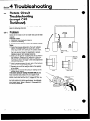
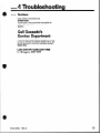
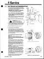
1
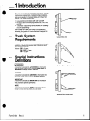
Service
Manual
SlidingArm
Paper Roll Clamps
Manual Number 667446
l
cascade@
corporation
Contents
Page
Number
INTRODUCTION, Section 1 ................
1-1
INSTALLATION INSTRUCTIONS, Section’2 . . 1-2
Truck System Requirements ...............
1-2
Prior to Installation. ......................
1-3
Installation .............................
1-4
Attachment Stop Blocks ...................
1-4
Prior to Operation. ......................
. 1-4
PERIODIC MAINTENANCE, Section 3 .......
1-5
TROUBLESHOOTING, Section 4 ............
1-6
SERVICE, Section 5 ......................
. 1-16
Clamp Removal and Installation ............
1-16
Arms.................................. 1-16
Arm Removal and Installation ............
1-16
Arm Disassembly and Reassembly,
Long-and-Short Arms .................
1-18
Arm Disassembly and Reassembly,
1-18
Link-type Swing Arms .................
Arm Disassembly and Reassembly,
Cam-type Swing Arms .................
1-19
Arm Disassembly and Reassembly,
1-20
C5P Swing Arm ......................
Arm Disassembly and Reassembly,
1-21
Old-style C4P and C4S Dockhands ......
Arm Disassembly and Reassembly,
New-style C4P and C4S Dockhands ..... 1-21
T-bar Arm Base/Arm Carrier Disassembly
1-22
and Reassembly. ....................
Sliding Arm Bushing Replacement.
1-22
Two-piece Style .....................
Sliding Arm Bushing Replacement,
1-23
One-piece Style .....................
1-23
Wear Bar installation. ..................
Cylinders, General Procedures .............
1-24
1-24
Cylinder Removal and installation. ........
1-25
Cylinder Disassembly. ..................
1-25
Cylinder inspection .....................
1-25
Cylinder Reassembly ...................
Cylinder Service. ........................
1-26
Restrictor Fittings. .......................
1-28
Restrictor Fitting Service. ...............
1-28
Restrictor Fitting Adjustment. ............
1-28
Revolving Connections. ...................
1-29
Revolving Connection, Cartridge-type
Check Valve Service .................
1-29
Revolving Connection, (and C5P Check
Valve) Removal and Installation. ........
1-30
Revolving Connection Service ............
1-31
Check Valve Service, C5P Clamps Only .... 1-32
Sideshifting Check Valve, C4S Dockhand. .... 1-32
Sideshifting Check Valve Removal and
installation .........................
1-32
Sideshifting Check Valve Service ..........
1-33
Rotator Drive Group ......................
1-33
Rotator Drive Group Removal and
installation .........................
1-33
Rotator Drive Group Disassembly and
Service ............................
1-34
Rotator Drive Group Reassembly .........
1-36
Motor. .................................
1-38
Motor Removal and installation. ..........
1-38
Motor Disassembly, Service, and
Reassembly ........................
1-39
Frame Assembly, all Models except C5P
and C4S ...........................
Sideshifting Dockhand ....................
1-41
Baseplate Removal .....................
1-41
Ring Gear/Bearing Assernbiy Removal. ... .1-41
Frame Assembly Service. ...............
1-42
Frame Reassembly ....................
1-43
Frame Assembly, C5P Models Only .........
1-44
Frame Disassembly and Reassembly. ..... 1-44
Frame Assembly Service. ...............
1-45
STANDARD LABOR TIMES, Section 6 ......
. 1-46
Form 5184
Rev. 0
Section
1 Introduction
This manual provides the installation instructions, periodic
maintenance requirements, troubleshooting procedures,
and service guides for Cascade Sliding Arm Paper Roll
Clamps. The models covered are:
l
l
l
Long-and-Short-Arm Models C3P, C4P, and C6P
Parallarm (Short-and-Swinging) Models C3P, C4P, C5P,
and C6P
“Dockhand” (equal-length arms) Models C4P (rotating)
and C4S (sideshifting)
Each Sliding Arm Paper Roll Clamp is a hydraulically
actuated, two-function lift truck attachment designed for
paper roll handling.
1.1
Truck System
Requirements
Long-and-Short
Arm
Pressure: Your lift truck should supply sufficient hydraulic
pressure to handle the heaviest load. PRESSUREMUST
NOT EXCEED 2000 PSI.
Volume: C3P-10 gpm
C4P, CSP-15 gpm
C6P-20 gpm
1.2
Special Instructions
Definitions
WARNING
Parallarm (Short-and-Swing
Arm)
A statement preceded by AWARNINGis information
that should be acted upon to prevent bodily injury. A
WARNING is always inside a ruled box.
CAUTION
A statement preceded by CAUTION is information that
should be acted upon to prevent machine damage.
IMPORTANT
A statement preceded by IMPORTANT is information
that possesses special significance.
NOTE
A statement preceded by NOTE is information that is
handy to know and may make your job easier.
Dockhand
Form 5184
Rev. 0
(Equal Length Arms)
1
2 Installation Instructions
Section
.
WARNING
truck/attachment combination is a
responsibility of the original truck
manufacturer and may be less than
Truck System
Requirements
2.1
l
l
l
l
Truck relief valve setting: 2000 psi maximum.
Volume: C3P-10 gpm
C4P, C5P-15 gpm
C6P-20 gpm
Recommended hose and fitting size: No. 8 (1/2 inch
ID) with minimum fitting orifices of 13/32 inch.
Truck carriage must conform to the Industrial Truck
Association (ITA) dimensional standards as shown in
the following chart.
,a
Mounting
l
Make sure the truck carriage is clean and the notches
are undamaged.
Form 5184
Rev. 0
Section
2.2
2 Installation Instructions
Prior to Installation
NOTE
1. Install the hydraulic hoses to the truck junction
blocks using the correct Cascade Attachment Installation Kit (C-663532 for C4S Sideshifting “Dockhands,”
C-663585 for all other clamps).
Connector
9O’Elbow
90”
Elbow
No. 8 Hose
/
I Connector
OR,
use hoses and fittings as shown in Figure 1 or 2. Be
careful not to pinch, twist, or otherwise damage the
hoses.
1
-’ i
I To Truck
! Junction
ibi
Function,
in order of
location
from
operator
&en
j ._ To Truck
Junction
Block
7
-. -
IMPORTANT
In order to conform to industry standard practice, the
hoses should be connected to the truck auxiliary valves
as indicated by the following chart.
Close
-~
..--ICheck Valve’
Figure 1. Plumbing Diagram, Model C4S
Sideshifting Dockhand
Attachment
Movement
Motion of the operator’s
Clockwise
Rearward or Up
hand
Rotate
I
Counterclockwise
Forward or Down
I
Clamp
Rearward or Up
Release
Forward or Down
NOTE
Clamp
9O’Swivel
Elbow
90’ Swivel
Elbow
Viewed
From the Driver’s Seat
Straight
Thd
Connect
90” Straight
..-U
\
/
i
CAUTION:
I
\
Connect
To Tryk
$;E;on
Figure 2. Plumbing
I
45’ Swivel
Elbow
Diagram,
+i
90” Swivel
Elbow
Clockwise
Clockwise
T
to Truck
Junction
Block
1
Models C3P, C4P, and C6P
2. Flush the-hoses as follows to prevent damage to the
rotator motor and the revolving connection (check
valve on sideshifting Dockhands).
a. Connect the hoses that go to the rotator motor
together.
b. Connect the hoses that go to the revolving
connection together.
c. On sideshifting Dockhands, connect each pair of
hoses from the truck junction blocks together.
d. Start the truck and actuate both truck control
valves in both directions for about 30 seconds to carry
any debris left in the hoses to the truck hydraulic tank
and filter.
Form 5184
Rev. 0
3
2 Installation Instructions
Section
Installation
2.3
0
Using a suitable hoist and chain, position the clamp as
shown and remove the lower mounting hooks.
0
Position the truck close enough so the hoses on the
junction blocks can be connected to the attachment.
0
Connect the hoses to the attachment as shown in
Figure 1 or 2.
0
Raise the truck carriage and engage the attachment
upper mounting hooks. Make sure the centering block
on the attachment aligns with the center notch on the
carriage.
Position Clamp
On Wood Block
and Remove
Lower Mounting
Hooks
IMPORTANT: Some models have a positioning block
welded to the upper left-hand mounting hook. Center
the attachment on the carriage, making sure the positioning block is engaged in a notch on the carriage.
0
Tilt the mast back and install the lower mounting
hooks. Lube-torgue the capscrews as follows:
I
I
/
Raise Carriaae
C3P 174-76 ft.-lb.
C4P Sideshlftlng
All others
Dockhand and C5P
64-69 ft.-lb.
85-90 ft.-lb.
Attachment stop
Blocks
2.4
Cascade recommends that steel’stop block kit
C-669344 be permanently welded on each side of the
truck carriage upper crossbar adjacent to each
attachment upper mounting hook. To perform the
installation:
Attachment
Upper
/Mounting
Hook
1. Position the blocks adjacent to the upper mounting
hooks. The blocks should not extend behind the flat of
the carriage upper crossbar (dimension A).
Steel Stop Block
2. Weld the blocks in place. Make sure you protect
adjacent hoses and hydraulic components from weld
splatter.
Prior to Operation
2.5
0
Check the cylinder anchor nuts to make sure they are
secure. If your clamp has old-style anchor nuts, make
sure the spring retainer is in place. If you have newstyle anchor nuts, make sure they are properly staked.
P
Make Sure
Spring
Retainer
is in Place
@ Before picking up a load, operate the attachment
through a full cycle to force any air from the system to
the truck hydraulic tank. Check for leaks.
@ Pick up a maximum load and operate the clamp. If the
clamp does. not function correctly, recheck the plumbing. If the clamp drops the load, contact Cascade’s
Service Department, telephone 800-547-5266 (toll-free),
or, in Oregon, call 666-1511.
WARNING
OLD-STYLE
CYLINDER
ANCHOR NUT
NEW-STYLE
CYLINDER
ANCHOR NUT
Form 5184
Rev. 1
Section
3.1
3 Periodic Maintenance
100 Hour Maintenance
Every time the lift truck is serviced or every 100 hours of
truck operation, whichever comes first, complete the
following maintenance procedures.
Cl Check the cylinder anchor nuts for security.
0 Check the edge of the contact plates for wear or sharp
nicks that could damage or tear paper rolls. Replace
the contact plates if necessary.
IMPORTANT:
After completing any service procedure, always test
each function through 5 complete cycles. First test
the clamp empty to bleed excess air trapped in the
system. Then test each function with a load to
make sure the clamp operates correctly before
returning it to the job.
0 Check the pivot pins securing the contact plates and
contact plate links. If a concentration of wear is
visible, replace the pins.
3.2
500 Hour Maintenance
After each 500 hours of lift truck operation, in addition to
the 100-hour maintenance procedures, perform the following procedures.
II Lubricate the ring gear/bearing assembly with wheel
bearing grease (except C4S sideshifting Dockhands).
Rotate the clamp one full turn during lubrication.
Cl Remove
retorque
to 65-70
Replace
the plug on the back of the baseplate and
all the ring gear/bearing assembly capscrews
ft.-lb. (except C4S sideshifting Dockhands).
the plug.
0 Remove the plug on the
case and fill to capacity
Lubricant (Cascade part
Keystone WG-1 (except
Replace the plug.
side of the rotator drive gearwith Cascade Rotator Drive
number C-656300) or
C4S sideshifting Dockhands).
q Retorque the mounting hook capscrews.
torque specifications
3.3
Use the
shown in Section 2.
1000 Hour Maintenance
After each 1000 hours of lift truck operation, in addition
to the 100-hour and 500-hour maintenance procedures,
perform the following procedures.
III Check the arm bushings. If they are worn, marred, or
deeply scratched; replace the bushings.
0 Check the swing-arm and Dockhand-arm pivot
bushings. If bushings are scored or worn, replace
them.
Cl Check swing-arm and Dockhand-arm pivot pins. If the
chrome plating is pitted or worn through, replace the
pins.
3.4
2000 Hour Maintenance
After each 2000 hours of lift truck operation, in addition
to the 100-hour, 500-hour, and 1000-hour maintenance
procedures, perform the following procedure.
0 Replace all sliding an-n bushings.
Form 5184
Rev. 0
5
4 Troubleshooting
Section
General Procedures
4.1
WARNING: Before servicing any
hydraulic component, relieve
pressure in the system. Open the
arms 1 or 2 inches, turn the truck off,
and open the truck auxiliary valves
several times in both directions,
After completing any service procedure, always test the unit through
several cycles. First test the attachment empty to bleed air trapped in
the system to the truck system. Then
test the attachment with a load to be
sure it operates correctly before
returning it to the job.
Stay clear of the load while testing.
Do not raise the load more than 3
inches off the floor while testing.
Truck System Requirements
4.1.1
Pressure Gauge
/
Pressure: Your lift truck should supply sufficient hydraulic
pressure to handle the heaviest load. PRESSURE MUST
NOT EXCEED 2000 PSI.
ivel Nut
n Tee
Volume: C3P-10
gpm
C4P, C5P-1.5 gpm
C6P-20
gpm
Pressure Gauge
4.1-2
i
Tools Required
In addition to a normal selection of hand tools, you will
need:
l
l
l
.
l
Needle Shutoff
Valve
Swivel Nut
Run Tee
/lose
/
Drain Hose
Two pressure gauges capable of measuring pressure
to 2500 psi.
Two No. 6 swivel nut run tees (37” JIC) suitable for
mounting gauges.
Two No. 8 swivel nut run tees (37’ JIG) suitable for
mounting gauges.
I
\
IMPORTANT:
Make Sure The
Arrow Points in
This Direction.
Male Connector
Two needle shutoff valves, rated for 2500 psi service;
minimum. (Recommended supplier for needle shutoff
valves: Marsh Instrument Co., Skokie, Ill.)
Two steel sleeves as shown by the accompanying
illustration
Install the gauges in the tees. Use No. 6 tees for
troubleshooting clamping circuits and use No. 8 tees for
troubleshooting rotator circuits.
1-i/w*
I
-17
Steel Sleeve
2-112”
For some tests, you will install the needle valves and
drain lines in conjunction with the No. 6 gauge
arrangements.
6
Form 5184
Rev. 0
.
I
:a
Troubleshooting
Section4
Get All The Facts BeforeYou
Begin Working On The
Clamp
4-3
It is important that you gather all the facts regarding the
problem before you begin service procedures. The best
way is to talk with the operator. Ask for a complete
description of the malfunction. The following guidelines
will help you decide where to begin your troubleshooting
procedures.
A. Clamp Circuit
l
Clamp drops the roll after it has been picked up.
l
Clamp will not carry rolls up to its rated capacity.
l
Clamp arms will not function properly.
If you encounter one of these problems, refer to
Paragraph 4.3.
B. Rotate Circuit (except C4S Dockhand)
l
Clamp will not rotate.
l
Clamp will not rotate rolls up to its rated capacity.
l
Clamp rotates in one direction only.
If you encounter one of these problems, refer to
Paragraph 4.4.
Form 5184
Rev. 0
7
Section
4 Troubleshooting
4.2
Plumbing
4.2.1
Hosing Diagram, All Except C4S dockhand
A
Restrictor
C:..:--
Note
Junction
Block
ARMS CLOSING
PRESSURE
Junction
Block
RETURN
Note
Al~yiliarv
Valve Ports
Junction
Block
A
Hose Reel
I
ARMS OPENING
PRESSURE
RETURN
8
-
Form 5184
Rev. C
.
Section
l
4.2-1
4 Troubleshooting
Hosing Diagram,All Except C4S Dockhand(Cont.)
Note: Auxiliary
Valve Ports
and Hose Reel Ports mav be
1 Reversed Fron n Those Shown. 1
Rotator
*-YMotor
Junction
Block
Check Valve
IC5P Only)
Revolving
Connection
ROTATE-(CLOCKWISE
PRESSURE
m
RETURN
-
SHOWN)
Hose
Reel
Ld
4.2-2
CircuitSchematic,All Except C4S Dockhand
1
w--II
Revolving
Connection
Rotator
“9
I1
-
-__
Junctioni
Block
.-
,
C5P ONLY
Revolving Connection
does
not have integral check valves;
check valves are separate
components.
I
-.
_-
Hose
Reel
r
I
Truck
Form 5184
Rev. 0
Hydraulic
Motor
9
Section
4.2-3
4 Troubleshooting
Hosing Diagram,C4S SideshiftingDockhand
Restrictor
Fitting
ARMS CLOSING
PRESSURE
7
RETURN
I
Junction
Block
Hose
Reel
1 \J
ARMS OPENING
PRESSURE
RETURN
10
I
,-
Block
I
“-1
Hose
Reel
Form 5184
Rev. 0
Section
4 Troubleshooting
4.2-3
Hosing Diagram, C4S Sideshifting Dockhand (Cont.)
Junction
Block
SIDESHIFTING
(SIDESHIFT LEFT SHOWN)
PRESSURE
-
RETURN
-
4.2-4 Circuit
Schematic,
C4S Sideshifting Dockhand
Cylinders
Ii
lifting
Valve
I
/
Truck
Form 5184
Rev. 0
Relief Valve
Truck
Hydraulic
Pump
11
4 Troubleshooting
Section
4.3
Clamp Circuit
Troubleshooting
There are four potential problem areas that could affect
clamping force.
l
Insufficient
l
External leaks.
hydraulic pressure.
l
Malfunctioning
l
Worn or defective
check valves.
cylinder seals.
To isolate the problem area, complete the following check
list in the exact sequence indicated.
General Pressure Test
0 To test the clamp system, rotate the attachment so the
arms are side-by-side (for vertical roll handling). Open
the arms fully.
•j Remove the bumper plate from the front of the
attachment.
0 Remove the arm cylinder rod-end nuts.
IMPORTANT: Refer to the procedures
Section 5, Paragraph 5.2-1, Step 2.
described in
0 Retract the cylinders far enough to slip the steel
sleeves over the cylinder rods.
0 Extend the cylinders and reconnect the rods to the
arms. It is not necessary to “lock” the nuts or install
the keepers.
0 Remove the supply hose to the rod end port of both
arm cylinders. Install the gauges into the open ports,
then connect the cylinder supply hoses to the gauge
tees.
0 Slowly retract the cylinders (arms moving together)
until the sleeves contact the cylinder ends. Make sure
the gauge assemblies do not interfere with the closing
arms. The cylinders are now blocked partially
extended.
•i Pull the clamp control handle to the “clamp”
and hold for a few seconds.
\
Slip On The Sleeves
position
Cl Return the handle to neutral. The gauges should
register within 100 psi of specified truck pressure. If
they do not, check the pressure delivered by the truck.
Refer to the truck service manual. Adjust and repair as
necessary. TRUCK PRESSURE MUST NOT EXCEED
2000 PSI. Recheck cylinder pressures.
End Restrictor
12
Form 5184
Rev. 0
Section
4 Troubleshooting
General PressureTest(Cont.)
I!
\
0 If the truck system is OK, watch the gauges. If either
or both registers a drop of more than 100 psi in one
minute, check for external leaks in the system. Refer
to the accompanying diagram. Repair the leaks and
recheck cylinder pressure. If there are no external
leaks, test the check valves as follows.
Cylinder
*
0 Remove the gauges from the cylinder rod-end ports.
Keep the gauges connected to the cylinder supply
hoses. Cap the open cylinder rod-end ports.
*
Check Valve
0 Attach the needle shutoff valves and drain lines to the
gauge tees. Put the drain lines into a suitable container. Open the needle valves no more than 1/2 to 1
full turn.
Cl With the truck idling, pull the clamp control handle to
“clamp.” Wait 4 or 5 seconds, then close the needle
valves tightly. Continue holding the clamp handle for a
moment to allow clamping circuit pressure to reach
the full truck relief setting.
I
Truck
Valve
L
POTENTIAL
EXTERNAL
LEAK POINTS
0 Watch the gauge.
l
l
If the gauges do not drop more than 100 psi in one
minute, the cylinder seals are leaking. Refer to Section
5, Paragraph 5.3 for service procedures.
If the gauges drop more than 100 psi in one minute,
the check valve is faulty. Refer to Section 5,
Paragraph 5.6 for service procedures (Paragraph 5.7
for C4S Dockhands).
Cl After making the necessary corrections, remove the
cylinder rod sleeves, reconnect all hoses, and replace
the bumper plate. Make sure the cylinder anchors are
secure. Refer to Section 5, Paragraph 5.2-1, Step 7 for
special instruction regarding cylinder anchor nuts.
q Cycle the attachment 4 or 5 times without and with a
load before returning the attach.ment to service.
Needle Shutoff
Call Cascade’s
Service Department
If you have carefully and accurately completed this check
list and you still have not solved the problem, call us. Our
Service Department is open from 10:00 AM to 8:00 PM
Eastern time.
Call 800-547-5266(toll free)
In Oregon,666-4511
Form 5184
Rev. 0
Restrictor
Fitting
Section
4.4
4 Troubleshooting
Rotate Circuit
Troubleshooting
(except C4S
Dockhand)
To isolate the problem area in the rotation system, complete the following check list.
Problem
4.4-1
Clamp will not rotate or will not rotate rolls up to its rated
capacity.
Probable causes:
l
Insufficient
0 Incorrect
l
truck hydraulic pressure.
roll handling.
Excessive back pressure in the truck hydraulic system.
Tests:
0 Check the pressure delivered by the truck hydraulic
system. A pressure drop of no more than 100 psi
below truck relief valve setting at the auxiliary valve
port is OK. If the pressure is not as specified, refer to
the truck service manual for adjustment or service.
PRESSURE MUST NOT EXCEED 2000 PSI.
0 Make sure the operator is gripping the roll as shown in
the illustration. Gripping a roll, especially a long one,
near its end, then attempting to rotate it requires a
tremendous amount of torque-often
times beyond the
capacity of the clamp.
Cl install a pressure gauge into each port of the hydraulic
motor (do not use the needle valve).
0 Securely grip a roll that weighs close to the capacity
of the clamp.
0 Rotate the roll and note the pressure readings on the
gauges during rotation.
LI\
Check Truck
System Pressure
Here
1
-Q
THIS
Torque
NOT THIS
If the lower pressure reading EXCEEDS 200 psi, you
have excessive back pressure in your supply circuit.
Check for restrictions such as numerous fittings and
elbows, hose sizes less than No. 8, clogged oil filter, etc.
Check For Pressure
If the lower pressure does NOT EXCEED 200 psi, and
the truck pressure is within specifications, the hydraulic
motor needs repair. Refer to Section 5, Paragraph 5.9-2
for service procedures.
14
Form 5184
Rev. 0
Section
a
4.4-2
4 Troubleshooting
Problem:
Clamp rotates in one direction
only.
Probable cause:
The pilot spool in the junction block that supplies the
rotator motor is jammed.
Solution:
Replace the junction block.
Call Cascade’s
ServiceDepartment
If you have carefully and accurately completed this check
list and you still have not solved the problem, call us. Our
Service Department is open from 10:00 AM to 8:00 PM
Eastern time.
Call800-447-5266
(toll free)
In Oregon,666-4511
Form 5184
Rev. 0
15
5 Service
Section
Clamp Removal and
Installation
5.1
0
Make sure the attachment is rotated so the arms are
positroned side-by-side (for vertical roll handling). Open
the arms completely.
0
Remove the lower mounting hooks. For reassembly,
lube-torque the lower mounting hook capscrews as
follows:
C3P
J
74-76 ft.-lb.
C4P Sideshifting Dockhand and C5P
Lower Carriage
and Back Truck
Away Slightly
64-69 ft.-lb.
All others 85-90 ft.-lb.
0
Position a wood block under the attachment frame.
Lower the mast carriage until the arm contact plates
are on the floor and the frame is resting on the block.
0
After making sure the attachment is securely positioned, continue lowering the mast carriage enough to
clear the upper mounting hooks. Back the truck away
a few inches to gain access to the hoses to the revolving connection (check valve on C4S sideshifting
Dockhands).
\
\
/aDisconnect
Hoses
~QiJ(J&
d
Lower Attachment
onto Block
\o
, %%:;fl::ki
See Step 2 For
Torque Values
WARNING
hoses, relieve pressure that might be
the truck off, open the truck auxiliary
control valves several times in both
0
Disconnect and cap the hoses to the attachment.
the hoses for ease in reconnecting.
0
For reinstallation, reverse the above procedures,
consult Installation Instructions, Section 2.
Tag
or
5.2
Arms
5.2-1
Arm Removal and Installation
Arm removal is easiest to perform with the attachment
mounted on the truck.
IMPORTANT: C5PSWING ARM CLAMPS ONLY. If you
are going to disassemble the swing arm of a C5P clamp,
first remove the arm from the arm carrier while it is still
on the attachment frame. Refer to Paragraph 5.2-5.
1. Rotate the clamp so the arms are positioned
side (for vertical roll handling).
16
side-by-
Form 5184
Rev. 0
Section
5.2-1
5 Service
Arm Removaland Installation(Cont.)
2. Fully extend the arms and remove the nuts retaining
the cylinder rods to the arm lugs. On old-style retaining
nuts, first remove the spring retainers.
Link
Bushing
Link Pin
Assembly
h
IMPORTANT: A new style retaining nut has a coneshaped locking washer swaged to the threads of the
nut. Locking is achieved when the washer is
“dimpled” into the groove in the end of the cylinder
rod. To “unlock” the nut, insert a punch or chisel into
the hole in the center of the cone-shaped washer and
pry up the dimple. If you’re careful, the nut may be
reused several times.
NOTE: Pressurizing the cylinders outward will increase
friction between the cylinder rod and the lug and may
make loosening the nuts easier.
3. Secure the arms with a suitable overhead
chain.
A
hoist and
WARNING: Make sure your
overhead hoist has a rated lifting
capacity of at least 1000 pounds.
4. LINK-TYPE SWING ARMS ONLY. Remove the links by
removing the link pin assemblies from the arms and
the attachment frame.
I
Link Pin Assembly
5. Retract the cylinder rods until they come out of
engagement with the arm lugs.
6. Pull the arms out of the clamp frame.
IMPORTANT: Each time the arms are removed, inspect the arm guide tubes on the revolving frame for
scoring. Minor scoring can be removed with a hone. If
the guide tubes are too badly damaged to use, the entire revolving frame must be replaced. Before installing
arm carriers, make sure the guide tubes are clean and
free of metal projections.
Make Sure
Washer
Lug
Sprilg
7. For reassembly, reverse the above procedures, except
for the following special instructions for cylinder
anchor nuts.
NOTE: When tightening cylinder anchor nuts,
pressurizing the cylinders outward will increase friction
between the cylinder rod and the lug and may make
tightening easier.
a. OLD-STYLE ANCHOR NUTS. Install the washer
onto the cylinder rod, then fit the cylinder rod into the
arm carrier. Install the sleeve, then thread on the nut.
Tighten the nut until the sleeve bottoms against the
washer. Back the nut off until it aligns with the slot in
the cylinder rod. Install the spring retainer. The
clearance between the lug and the washer should be
about 5/32 inch.
Sleeve
Nut
OLD-STYLE CYLINDER
ANCHOR NUT
NEW-STYLE CYLINDER
ANCHOR NUT
CAUTION: Do not attempt to remove the looseness or
damage to the assembly could result.
b. NEW-STYLE ANCHOR NUTS. Install the washer
onto the cylinder rod with the counterbore-side facing
outward (toward the nut), then fit the cylinder rod into
the arm carrier. Restrain the washer with a wrench
and torque the nut to: C3P, C4P-130-150
ft.-lb.,
C6P-205-235
ft.-lb. Lock the nut by staking the coneshaped washer with a case-hardened chisel. Be sure
the cone-shaped washer is driven into the slot in the
end of the cylinder rod.
CAUTION: Always use the hex-style washer with the
new-style anchor nut. DO NOT use the old-style
castellated nut with the hex-style washer.
Form 5184
Rev. 0
17
5 Service
Section
Arm Disassembly and Reassembly,
Long-and-ShortArms
52-2
Arm
The following procedures can be performed with the attachment on the truck and with the arms on the attachment. If the arms have been removed (Paragraph 5.2-1)
lay the arm assembly down with the arm vertical.
0
Remove the contact plate links by removing the link
pivot pin. The links are pivoted to the inside edge of
the contact plate to limit the travel of contact plate
articulation.
0
Remove the contact plate by removing the contact
plate pivot pin from the back of the contact plate. The
pin is secured by two pipe plugs.
0
For reassembly,
reverse the above procedures.
Arm Disassembly and Reassembly,
Link-type Swing Arms
5.2-3
Spring
h
The following procedures can be performed with the attachment on the truck and with the arms on the attachment. If the arms have been removed (Paragraph 5.2-1)
lay the assembly down with the arm vertical.
0
Remove the arm links (if they are not already
by removing the link pin assemblies from the
the attachment frame.
r
WARNING:
Secure the swing
with a suitable overhead hoist
chain.
IA
lx
.*A
Link
removed)
arms and
/a
1
0
arm
and
0
Remove the arm pivot pin assembly and separate the
arm from the arm base.
0
Remove the arm contact plate as described in
Paragraph 5.2-2.
0
For reassembly,
reverse the above procedures.
u
Contact Plate
To Reassemble,
Reverse Disassembly
Procedures
Link Pin
Assembl
Assembly
Remove
the Contact
Plate
M
6
Link-type
18
.-.Link
/
Contact Plate II
Contact Plate
’
“il
Link Pivot
Pin
9
Swing Arm Assembly
Plug A3
(typical)
Form 5184 Rev. 0
5 Service
Section
5.2-4
Arm Disassembly and Reassembly,
Cam-type Swing Arms
The following procedures can be performed with the attachment on the truck and with the arms on the attachment. If the arms have been removed (Paragraph 5.2-1)
lay the arm assembly down with the arm vertical.
0
Remove the two capscrews from the inside of the arm
base to relax the tension on the leaf spring assembly.
I
1
A
A
WARNING: Secure the swing arm
with a suitable overhead hoist and
chain.
@ Remove the arm pivot pin assembly and separate the
arm from the arm base.
0
Remove the two cam rollers from the top and bottom
of the frame.
0
Remove the contact plate as described in Paragraph
5.2-2.
0
Disassemble the leaf springs by removing the two
socket-head capscrews in the spring base.
NOTE: Your unit may have a different quantity of
springs than shown. During reassembly, make sure
you install the same number of springs you removed.
0
For reassembly, reverse the above procedures.
Lubricate the springs with graphite-base grease when
reassembling.
!
Remove the
Arm Pivot Pin
Cam-type Swing Arm Assembly (typical)
Link Pivot Pin
Remove the
Cam Rollers
Plate
Pivot Pin
Remove
the Springtension
Capscrews
0
1__,,P
ai
‘0
Reassembly
Form 5184
Rev. 0
-
v
Remove the
Contact Plate
19
5 Service
Section
Arm Disassembly and
Reassembly, C5P Swing Arm
5.2-5
IMPORTANT: The swing arm of a C5P clamp must be
disassembled as follows before removing the arm carrier
from the attachment.
0
Close the arms until the swing arm closes about 20°
0
Insert a steel drift pin through the hole in the back of
the arm base, then slowly close the arm until the drift
pin engages a hole in the spring retainer.
A
WARNING: Keep clear of the spring
when engaging or releasing the
dowel or drift pin.
0
Open the arm until the dowel in the spring retainer
can be removed.
0
Move the dowel to the hole in the spring retainer
closest to the drift pin.
0
Close the arm until the drift pin can be removed.
0
Remove the arm pivot pins and pull the swing arm
away from the arm base.
Remove the contact plates as described
5.2-2.
0
Remove the arm carrier as described in Paragraph
5.2-1.
@
For reassembly, reverse the above procedures, except for the following. special instructions for the
swing arm.
0
Install the arm carrier into the attachment frame.
Make sure the guide tubes are clean and free of
metal projections. Refer to Paragraph 5.2-1, Step 7.
@
Assemble the arm onto the arm base with the spring
relaxed (dowel removed).
@
Close the arm completely.
@
Insert a steel drift pin through the hole in the back of
the arm base and engage a hole in the spring
retainer.
A
20
ft.-lbs.
This Capscrewto
Insert Drift
1
Pin.
0
Open A
0
WARNING: Secure the swing arm
with a suitable overhead hoist and
chain.
0
@
to 440-450
Openprocess
the arm until
and repeat
the spring
the
A
@
Torque
Remove Dowel and
Insert in Hole Closest
to Drift Pin.
C5P Swing Arm Removal
in Paragraph
Arm Pivot
Contact
^.
-. Plate
WARNING: Keep clear of the spring
when engaging or releasing the
dowel or drift pin.
Open the arms and insert the dowel into the spring
retainer hole farthest from the drift pin.
@
Close the arm until the drift pin can be removed.
@
Repeat the process until one of the last two spring
retainer holes can be pinned by the dowel.
Contact
Plate
Form 5184
Rev. 0
5 Service
Section
5.2-6 Arm Disassembly and
Reassembly, Old-style C4P
and C4S Dockhands
Remove
the
Contact
-.
rrate
The following procedures can be performed with the attachment on the truck. If the arms have been removed
(Paragraph 5.2-1). lay the arm assembly down with the
arm vertical.
0
Remove the contact
plate as described in
Paragraph 5.2-2.
A
WARNING:
Secure the
arm with a suitable
overhead hoist and
chain.
Remove the torsion bar
from the arm pivot point.
0
Remove the torsion bar
retainer from the arm
pivot point.
0
Remove the top and
bottom pivot pins and
separate the arm from
the arm base.
0
Bar
Retainer
Arm Base
Bushings
e
~weR;ymbly,
Remove the
Pivot Pins
Disassembly
Procedures
For reassembly, reverse
the above procedures.
Old-Style Dockhand Arm
5.2-7
Arm Disassembly and
Reassembly, New-style C4P
and C4S Dockhands
eve
Zontact
The following procedures can be performed with the attachment on the truck. If the arms have been removed
(Paragraph 5.2-1) lay the arm assembly down with the
arm vertical.
Remove the contact
a
plate as described in
Paragraph 5.2-2.
b
A
WARNING: Secure the
arm with a suitable
overhead hoist and
chain.
Remove the
Torsion Bar
d
Remove the torsion bar
retainer from the arm
pivot joint.
Remove the bottom
pin/torsion bar assembly.
Remove the top pivot
pin and separate the
arm from the arm base.
For reassembly, reverse
the above procedures.
Form 5184
Rev. 0
0
For Reassembly;
Reverse
Disassembly
Procedures
New-Style Dockhand Arm
Q
Remove
the
Bottom
Pin/
Torsion
Bar
Assembly
21
5 Service
Section
T-bar Arm Base/Arm Carrier
Disassembly and
Reassembly
5.2-8
Your attachment may be equipped with either integral
arm bases or T-bar arm carriers. Integral arm bases
cannot be disassembled.
NOTE: Service replacement parts for all integral arm
bases are T-bar units which are interchangeable on your
attachment frame. Kits are available to convert integral
arm bases to the T-bar configuration. Consult the appropriate Cascade Parts Manual pages, or contact
Cascade Customer Service.
To disassemble
a T-bar arm base/arm
Remove and disassemble the arm as described in the
paragraph that applies to your attachment (5.2-1, 5.2-2,
5.2-3, 5.2-4, 5.2-5, 5.2-6, or 5.2-7).
0
Secure the arm base with a suitable overhead
and chain.
0
Remove the two T-bars and the cylinder anchor lug by
removing the retaining capscrews.
0
For reassembly,
hoist
reverse the above procedures.
Sliding Arm Bushing
Replacement, Two-piece Style
NOTE: An attachment with two-piece bushings may be
converted to the new style, one-piece configuration by the
installation of the appropriate One-Piece Bushing
Conversion Kit. Contact Cascade Customer Service for
information.
0
Remove the
Arm Assembly
carrier assembly:
0
5.2-9
0
* T-Bar Arm Carrier
emove the Bushings
Remove and discard the old long and short bushings.
To ease removal, spread the short bushing by inserting
a screwdriver blade into the bushing slot. Similarly, insert two screwdrivers into two opposing slots in the
long bushing to disengage the bushing retaining lip. It
may be necessary to drive off the long bushing with a
block and a hammer.
@ Install the long bushing. Spread the slots of the
bushing with screwdrivers as during removal. If the
bushing will not go over the arm carrier bar, heat it in
boiling water for 3 or 4 minutes to soften it. Make sure
the bushing retaining lip engages the groove in the
arm carrier bar.
0
Install the short bushing. Spread the bushing to ease
installation. Make sure the bushing fits into the outermost groove in the arm carrier bar.
0
Lubricate the bushings before assembling arm
carriers onto the attachment.
Short Bushing
Form 5184
Rev. 0
Section
5 Service
5.2-10
SlidingArm Bushing
Replacement,One-pieceStyle
5.2-11
Wear Bar Installation
Inspect the short arm tip for wear. It frequently wears excessively when the arm is dragged across the floor. To
reduce arm tip damage, install a wear bar as follows.
1. Order a wear bar (Cascade part number C-636736) or
make a wear bar from AISI 5160 HR (hot-rolled steel).
Cut the bar to match the width of the arm.
2. Weld the wear bar to the arm tip as shown. Use E7018
welding rod; pre-heat to 35O°F, post-heat to 900°F.
0.312
in.
Wear Bar
3. Make sure the welds are smooth to avoid paper roll
- damage during handling in close stacks.
4. Since the wear bar installation makes the arm slightly
thicker, make sure the operator knows so he can
compensate.
Weld All Around
Form 5184
Rev.0
23
Section
5 Service
Cylinders,General
Procedures
5.3
Frame
CylinderRemovaland
Installation
5.3-1
0
Rotate the attachment so the arms are positioned
by-slde (for vertical roll handling).
0
Extend the arms past the width of the frame.
0
Remove the cylinder rod anchor nuts.
side-
IMPORTANT: Refer to the procedures pertaining to
cylinder anchor nuts as described in Paragraph 5.2-1,
Step 2.
0
Retract the cylinder rods until they come out of
engagement with the arm lugs.
0
Remove the bumper plate.
WARNING
Plate
0
Remove and tag the hoses to the cylinders. Cap the
hoses and the cylinder ports.
@
Remove the cylinder shell anchor nuts (Paragraph
5.2-1, Step 2).
0
Lift the cylinders away from the clamp frame.
0
Installation
is a reverse of removal.
IMPORTANT: Refer to the procedures
anchor nuts, Paragraph 5.2-1, Step 7.
0
24
pertaining to
Operate the attachment through several full cycles to
force air in the system to the truck hydraulic tank.
Check for leaks.
Form 5184
Rev. 0
5 Service
Section
l
CylinderDisassembly
5.3-2
l
l
Use a pin spanner wrench to remove the threaded
washer that secures the retainer in the cylinder shell.
When servicing a cylinder, clamp it in a soft-jawed
vise. Clamp the cylinder and the rod on the major
diameter at the extreme end only. Never clamp the
cylinder rod sealing surface.
l
V-seals will slide off the piston easily. To gain access
to the rod seals, remove the self-adjusting brass
bushing (if equipped) from the retainer after the retainer has been removed.
Pin Type Spanner Wrench
CylinderInspection
5.3-3
l
Inspect the rod, piston, and retainer for nicks or burrs.
If deeply gouged, replace the part. Minor nicks and
burrs can be removed with an emery cloth.
NOTE: A minor nick is one that will not cause a
bypass of oil when the cylinder is operating.
l
l
Do Not Clamp Rod
on Threaded or Sealing
Surfaces, Clamp Only
at Extreme End of
Major Diameter.
Inspect the inside of the cylinder shell and remove any
minor nicks and burrs (see Note, above) with a butterfly hone. Replace the cylinder shell if it is deeply
gouged.
Inspect the self-adjusting brass bushing that fits inside
the retainer (if equipped). If the ID is scored, the
bushing should be replaced.
CylinderReassembly
5.3-4
l
l
l
l
Lubricate all new seals with a mixture of petroleum
jelly and hydraulic oil before installing.
Carefully note the direction of V-seals. If they are installed backwards, the seals will not seal properly.
Refer to the illustration of the cylinder you are
servicing.
Always reassemble the rod assembly by sliding the retainer on first, then the piston assembly. Install and
torque the piston retaining nut before sliding the rod
assembly back into the shell.
Clamp Shell Only
at Extreme
Ease End.
When reassembling a cylinder, always observe all
torque values as shown on the appropriate illustration.
Form5184
Rev. 0
25
Section
5 Service
5.4
CylinderService
Select the illustration that represents the cylinder you are
servicing and perform the following procedures. Read the
General Procedures, Paragraph 5.3, before proceeding.
0
Remove the setscrew from the threaded washer.
0
Q
Remove the threaded washer.
0
Remove the nut securing the piston to the rod.
0
Remove the piston, retainer, and spacer (if equipped)
and replace all seals.
0
Remove the self-adjusting brass bushing (if equipped)
from the retainer to gain access to the rod seal.
0
Reassembly is a reverse of disassembly.
Pull the rod assembly out of the shell.
Remove the Threaded Washer 0
Remove the
Rod Assembly
Remove the Nut
For Reassembly,
C3P - 130-150
C4P - 300-350
26
ft.-lb.
ft.-lb.
Remove the Piston, Spacer,
and Retainer and Replace
Ail Seals.
Form 5184
Rev. 0
Section
a
5.4
5 Service
CylinderService (Cont.)
Remove the Threaded
Washer
For Reassembly,
Lube-Toraue
to;
0
Remove the
Rod Assembly
\
Remove the Nut
pi%zid
’ - 130-150
ft.-lb.
C4P - 300-350
ft.-lb.
--^^_
^_^ I
CtiP
- JZS-3sJ
ft.-ID.
\
\n
Remove the
Bushing from
the Retainer
s
__
Remove the Setscrew
\ II
\
,
For Reasselmblv.
Lube-Torqr Je to:
C3P and Cf iP - 10-l
r.“rn
0 ,r
,b.+r-o-,Jft.-lb.
I
1
I
I
Remove the Piston, Spacer,
and Retainer and Replace
All Seals.
Washer
1 For Reassemblv.
I?
h
Removethe
Piston
and Retainer and
Replace All Seals
Rev.0
2 ft.-lb.
a
Remove the Threaded
Form 5184
I
Remove the Setscrew
Remove the
Bushing from
the Retainer.
27
5 Service
Section
Restrictor Fittings
5.5
An adjustable restrictor fitting is installed in the port of a
cylinder to control the flow of hydraulic oil, and,
therefore, arm speed.
RestrictorFitting Service
5.5-1
Restrictor
Fitting
WARNING: Before disassembling a
restrictor fitting, relieve pressure that
might be in the hydraulic system
Replace the O-Ring
Remove the Setscrew
auxiliary control valves several times
5.5-2
0
Remove the jam nut from the setscrew.
0
Remove the cap from the restrictor
0
Unthread and remove the setscrew.
0
Replace the O-ring:
0
For assembly, reverse the above procedures.
Lubricate the O-ring with STP.
Body
fitting body.
0
Assembly is the
Reverse of
Disassembly
RestrictorFitting Adjustment
Restrictor fittings should be adjusted so that when one
arm bottoms during opening or closing, the other arm is
no more than 2 inches from bottoming. Before adjusting,
make sure the truck hydraulic system provides the
specified volume output as follows:
C3P-10
gpm
C4P, C5P-15
gpm
C6P-20
gpm
To adjust:
1. Loosen the jam nut on each restrictor
2. Screw both setscrews
off two full turns.
3. Operate the attachment
moving slower.
fitting.
in until they bottom, then back
to determine
which arm is
4. Back off the setscrew on the slower arm until arm
speed is equalized.
5. Back off both setscrews equally until desired arm
speed is achieved without losing equalization.
6. While holding the setscrew with a screwdriver,
the jam nuts.
28
tighten
Form 5184
Rev. 0
5 Service
Section
l
RevolvingConnections
5.6
The revolving connection has two cartridge valves located
in the valve body except the C5P. The C5P does not have
check valves integral with the revolving connection. Instead, there are two separate check valve assemblies
mounted near the outside end of the attachment frame.
Refer to Paragraph 5.6-5 for service procedures.
The C4S Sideshifting Dockhand does not have a revolving
connection. Instead, it has a sideshifting check valve. To
service the sideshifting check valve, refer to Paragraph
5.7.
Back-Up Ring
RevolvingConnection,
Cartridge-typeCheck Valve
Service
5.6-4
Back-Up Ring
\
The following procedures can be performed with the
attachment on the truck.
0
Remove the cylinders as described in Paragraph
5.3-1.
0
Remove the four supply hoses and fittings from the
front of the revolving connection valve body.
0
Remove the two hex-head cartridge valves on the
front of the revolving connection. Thoroughly clean
the parts.
0
a
are not
Shaft
Inspect Cartridges
Replace all O-rings and backup rings.
CAUTION: Backup rings must be wound as shown to
avoid seal damage during cartridge installation.
O-rings must be installed on the pressure side of the
groove.
IMPORTANT: If leakage is visible between the shaft
and valve body, the shaft seals must be replaced. To
replace shaft seals, the revolving connection must be
removed from the attachment. Refer to the procedures in Paragraphs 5.6-2 and 5.6-3.
0
Form 5184
Installation of the cartridge valves is a reversal of
removal. Before installing each cartridge, lubricate
the O-rings.
Rev. 0
Remove Hoses
and Fittings
P
Inspect the cartridge valve assemblies for cut or
defective external O-rings.
NOTE: Internal cartridge valve components
serviceable.
0
O-Ring
0
Install
Cartridge
Valves
Section
5 Service
’
RevolvingConnection(and
C5P Check Valve) Removal
and Installation
5.6-2
To service the check valves
on ball-and-plunger-type
revolving connections or to
service the revolving connection shaft. the revolving
connection must be removed
from the attachment.
0
Remove the attachment
from the truck as described in Paragraph 5.1.
0
Remove the cylinders as
described in Paragraph
5.3-1.
0
Remove, cap, and tag the
cylinder supply hoses
from the revolving connection valve body.
0
Remove, cap, and tag the
truck hoses to the revolving connection shaft, extending out the back of
the attachment.
0
Remove the shaft keeper
bar (two locking bars on a
C5P).
0
Pull the revolving connection out of the attachment.
Remove the Revolving
Remove
Hoses
,
d
Remove the single retaining capscrew securing
each check valve to the
attachment frame.
0
Installation of the revolving connection is a reversal of removal.
CAUTION: ALL
REVOLVING CONNECTIONS EXCEPT C5P The
shaft location hole
marked “X” must be
engaged by the horizontal
keeper bar.
0
Remove Shaft
Keeper
?
;\
Remove the
Check Valve
(Both Sides1
/”
C5P Revolving Connection Assem
@ C5P CLAMPS ONLY. To
remove the two check
valve assemblies,
remove, cap, and tag the
hoses to each check
valve.
0
d
D
Remove the
Hoses
(Both Sides)
J& ;v
Revolvina
Check
Remove the
Locking Bars
Revolving
Connection
Install the attachment
onto the truck as
described in Section 2.
See CAUTION,
Step 9
Form 5184
Rev. 0
5 Service
Section
emove and Replace
Rings and Back-Up
RevolvingConnectionService
5.6-3
Rings
IMPORTANT: Service the revolving connection in a clean
work area.
0
Remove the snap ring(s) from the revolving
connection shaft.
0
Remove the shaft from the body. On C5P revolving
connections, also remove and inspect the shaft bearing.
CAUTION: Remove any paint or burrs from the shaft
end and snap ring groove(s) before pulling the shaft
out of the valve body to prevent damage to the valve.
0
Clean the parts and inspect the shaft bore for scoring.
If the bore is scored, the valve body must be replaced.
Note the position of the O-rings and backup rings,
then remove them from the valve shaft. Be careful
not to scratch the grooves.
0
8
Check the shaft grooves for rough edges or
scratches. Remove minor imperfections with fine
emery cloth. If the scratches cannot be removed,
replace the shaft.
NOTE: A minor imperfection is one that will not
cause a bypass of oil when the revolving connection
is operating.
0
Service cartridge-type check valves as described in
Paragraph 5.6-1. To service ball-and-plunger-type
check valves, remove the plugs or hose fittings
securing the ball checks and the plungers. Remove
the balls, springs, guides, and plungers. Thoroughly
clean the parts.
0
Inspect the valve seats for scoring or elongation. The
valve seats can be reseated by tapping a ball into its
seat with a brass punch. If the seat cannot be
reseated, the valve must be replaced.
Inspect the Seats
B”::“ger A
Ball and Plunger-type
Revolving Connection
22
l
q;;;;
Remove the Plugs
the Shaft
Grooves
Inspect the balls for nicks and scratches.
8.
Inspect the pilot bores. They should be smooth and
free of scoring. If you cannot smooth minor irregularities with an emery cloth, replace the valve.
@
With the ball and seat only in place, attach a hose
from
the truck junction block to each ball port to test
. . .
ror leakage.
A
@
Cartidge-type
Revolving Connection
Remoie the
Snap Ring
WARNlNG: Examine the pilot bores
with a mirror to avoid the possibility
of getting oil in the face.
Remove the
Snap Ring
P
Pressurize the line and examine each pilot bore for
leakage. If there is no leakage, reassemble the check
valves. If leakage is present, remove the hose and
reseat the balls by tapping them into their seats with
a brass punch. Retest. If the balls cannot be
reseated, the valve must be replaced.
Install new O-rings and backup rings on the revolving
connection shaft. Be careful not to distort the seals.
@
@
Form5184
Rev.0
C5P Revolving Connection
Remove and inspect
the Shaft and Bearing
Replace O-Rings
and Back-Up Rings
Reassembly of the revolving connection is a reversal
of disassembly. Apply STP to the shaft O-rings to
ease reassembly. Rotate the shaft into the body to
prevent “rolling” the O-ring seals. Be careful not to
damage the valve bore.
NOTE Ball-and-plunger-type revolving connection
valve bodies and shafts are not available as replacement parts. They must be replaced by cartridge-type
revolving connections, which are interchangeable
with ball-and-plunger types.
Service the Check Valves.
See Paragraph 5.6-1
NOTE
5 Service
Section
l
Check Valve Service,C5P
Clamps Only
5.6-4
Remove the Plug
5.7
5.7-1
32
@
Remove the plug securing the ball check and spring.
0
Remove the plug securing the plunger.
0
Inspect the valve seat for scoring or elongation. The
valve seat can be reseated by tapping the ball into its
seat with a brass punch. If the seat cannot be
reseated, the valve body must be replaced.
0
Inspect the ball for nicks and scratches.
0
Inspect the pilot bore. It should be smooth and free
of scoring. If you cannot remove minor irregularities
with an emery cloth, replace the valve body.
0
Reassembly of the check valve is a reversal of
disassembly.
Pilot
Bore
SideshiftingCheck
Valve, C4S Dockhand
SideshiftingCheck Valve
Removaland Installation
0
Remove the attachment
from the truck as
described in Paragraph
5.1.
0
Remove, cap, and tag
the cylinder supply
hoses from the check
valve.
0
Remove, cap, and tag
the truck hoses to the
check valve.
0
Remove the check valve
by removing the
capscrew securing the
valve to the attachment
frame.
0
Installation of the check
valve is a reversal of
removal.
0
Install the attachment
onto the truck as
described in Section 2.
Form 5184
Rev. 0
5 Service
Section
SideshiftingCheck Valve Service
5.7.2
IMPORTANT: Service the check valve in a clean work
area.
0
Remove the hose fittings from the valve body and
remove the balls, guides, and springs. Clean the
parts.
0
Remove the allen-head plugs and remove the
plungers and spacers. Clean the parts.
0
Inspect all parts. Worn guides and plungers, weak or
broken springs, and nicked balls should be replaced.
0
Inspect the pilot bores. They should be smooth and
free of scoring.
0
With the ball and seat only in place, attach a hose
from the truck junction block to each ball port and
test for leakage.
A
E$onents
WARNING: Examine the pilot bores
with a mirror to avoid the possibility
of getting oil in the face.
0
Pressurize the line and examine each pilot bore for
leakage. if there is no leakage, reassemble the check
valve. If leakage is present, remove the hose and
reseat the balls by tapping them into their seats with
a brass punch. Retest. If the balls cannot be
reseated, the valve must be replaced.
@
Reassembly of the sideshifting check valve is a
reversal of disassembly.
l
Remove
Rotator Drive Group
5.8
Your attachment may be equipped with either a cushioned rotator drive group or an uncushioned unit.
Cushioning is achieved by the installation of cone-shaped
spring washers on both sides of the worm, powered by
the rotator motor. The worm gear is in mesh with the
rotator ring gear. Therefore. shock loads applied to the attachment arms are transferred to the worm through the
worm gear and are absorbed by the spring washers.
Rotator DriveGroup Removal
and Installation
5.8.1
@
Remove the attachment from the truck as described
in Paragraph 5.1.
0
Remove the rotator gear drive case retaining
capscrews and remove the gearcase from the attachment baseplate.
WARNING
Remove Capscrews
rotate. Keep clear of the baseplate to
0
Service the rotator drive group as described in
Paragraphs 5.8-2 and 5.8-3.
0
Reinstallation of the rotator drive group is a reversal
of removal.
0
Install the attachment onto the truck as described in
Section 2.
Form 5184
Rev. 1
33
Section
5 Service
5.8-2 Rotator Drive Group
Disassembly and Service
Drain the lubricant from the gearcase. Lay the gearcase (pinion down) on 4 X 4’s placed on either side of
the pinion.
Remove the rotator motor as described in Paragraph
5.9-1. Motor service procedures are described in
Paragraph 5.9-2.
Remove the capscrews
retaining the gearcase cover.
On all models except the C5P, remove the capscrew
from the center of the cover and replace it with a
3/8-inch-16 UNC capscrew 2 inches long. Turn the
capscrew clockwise while lightly tapping the side of
the cover with a plastic-head hammer to loosen it.
C5P clamps do not have the center screw.
Remove the end cap and bearing. The end cap is
secured by capscrews except the C5P, which is
secured by a snap ring and plug.
Remove the worm and spring washers (if equipped).
Remove the snap ring from the pinion shaft.
Using a gear puller, remove the worm gear from the
pinion shaft.
Remove the Woodruff key from the pinion shaft.
Press the pinion out of the gearcase.
Press the pinion seal (if equipped) and bearing out of
the gearcase.
Clean and inspect the components. Replace any item
that is worn or galled. Remove any burrs with an
emery cloth or small hand grinder.
Remove Screw and Replace
with a 3/6”-16
UNCx2”
Capscrew.
Loosen the Cover by Turning
Capscrew Clockwise while
Lightly Tapping the
Side of the Cover.
Press Pinion
Out of Gearcase
Press Seal and Bearing
out of Gearcase
Use Gear Puller
to Remove Worm
Remove Worm
and Spring Washers
Bearing
Remove
Snap Ring
d
CAUTION:
Some units will have this style relief fitting
in the end cap. These units may have damaged ball thrust
bearings due to low rotator fluid.
Cascade has a drive box
lube kit available which provides new ball thrust bearings
and a new pressure relief fitting.
See Technical Bulletin 114
for comblete ordering instructions.
34
Form 5184
Rev. 1
Section
a
5.8-2
5 Service
Rotator DriveGroup
Disassemblyand Service(Cont.)
. .----.
r
m
Press Pinion
out of Gearcase
Elc.mn,m Wnnlir, rff
Press Bearing Out
nf
---.-I”-
G=arracP
:
Remove Worm Gear
P
Bearing
/
\I/ Remove
End
Lube-Torque
b Plua and
to:
C5P Unit
Remove Cover d ’
Form 5184
Rev.0
d
Drain Lubricant
35
5 Service
Section
Rotator DriweGroup
Reassembly
5.8-3
0
Press the
using the
C-664620.
flush with
bearing into the housing from the inside
special tool, Cascade part number
Make sure the bearing is fully seated and
the inside of the gearcase.
0
Support the bearing from the inside with the special
tool and press the pinion into the bearing from the
outside.
0
install the Woodruff key into the pinion shaft.
0
Press the worm gear onto the pinion shaft, making
sure you align it with the Woodruff key.
@
Press the bearing onto the pinion shaft.
0
Install the snap ring.
0
Assemble the spring washers, spacers (if equipped),
and ball thrust bearings (See Caution below) on the
worm shaft and install in the housing.
CAUTION: The ball thrust bearing must be
assembled on the worm with the thickest portion of
the outer race (the side stamped with the
manufacturer and part number) facing away from the
washers.
Spring
Washers
Small
Spay
Worm
\
Small
Spacer
Large
Spacer
-- ~yj-q/m=vy-~
Spring
Washers
Thrust
Bearing
Gear
l6 WASHER
CUSHION DRIVE
Assemble Washers,
Spacers, and Bearings
on Worm and install
in the Housing.
Note: Some Units
Do Not Have
Spring Washers.
Press Worm Gear
onto Pinion Shaft
Press Bearing
onto Pinion Shaft
38
Form 5184
Rev. 1
5 Service
Section
Rotator DriveGroup
Reassembly(Cont.)
5.8-3
0
Install the end cap. If the gap on cushion drive units
is greater than that shown, the spring washers are incorrectly stacked. Remove the worm and restack the
washers.
0
Alternately tighten the endcap capscrews 1/2 of a
turn. Lube torque the capscrews to 7-10 ft.-lbs. On
C5P units, install the plug and snap ring.
@
Install the cover.
@
Install the motor.
@
Fill the gearcase with 44 fluid ounces of Cascade
Rotator Fluid (Cascade part number C-656300).
NOTE: C-656300 = 32 fluid ounces.
@
Install the gearcase onto the attachment baseplate.
Capscrews l/2 of a Turn
ml
I
Fill Gearcase with
LubflCant
Install the Motor
3
Lube Torque Retaining
Nuts to: 15-20ftAbs.
I
Install Gearcase to Baseplate
Form 5184
Rev. 1
37
5 Service
Section
Motor
5.9
5.9-1Motor Removaland
Installation,Revolving
Clamps Only
The rotator motor can be removed for service with the
attachment on the truck.
WARNING
hoses, relieve pressure that might be
the truck off, open the truck auxiliary
control valves several times in both
0
Remove, cap, and tag the supply hoses to the motor.
0
Remove the motor from the rotator drive assembly by
removing the six retaining nuts. Slide the motor out
of engagement and remove the coupling and key
from the motor shaft. A small amount of rotator fluid
might spill when the motor is removed.
@
Clean the motor and gear case mating surfaces with
solvent, Apply LOCTITE515 sealer to these surfaces.
Install the motor and tighten the retaining nuts to a
torque of 15-20 ft.- Ibs. (Lubed).
b
Remove Nuts’
-1
CAUTION: Because the threaded part on the motor is
tapered, overtightening the fitting in the port will split the
housing. Fittings should be snug but not overtightened.
Install reducers and fittings as follows:
Thread hose fitting (A) into bushing(B) until tight. Fit the
assembly of the bushing and fitting (A + B) into the
housing (C).Tighten the bushing (B) only. Any attempt
to tighten the hose fitting after installation in the
bushing may result in a cracked housing.
CAUTION: If rotator fluid was spilled when the motor
was removed, perform the following:
0
Remove the plug at the top of the side cover.
0
Fill the gearcase to the plug hole level with Keystone
WG-1 lube (Cascade part no. C-656300). Install the
plug.
Fitting
38
Bushing
Housing
Form 5184
Rev. 1
Section
5.9-2
5 Service
Motor Disassembly and
Reassembly
Cascade only services the adapter and cover, the drive
shaft and the seal kit which includes the seal seat and seat
assembly and the 2 large O-rings. Due to cost, if any other
parts need replacement, it is cost effective to replace the
complete motor assembly. The instructions below are for
replacing the seal kit, drive shaft, adapter and cover only.
Remove Capscrews
For Reassembly Lube Torque
Opposite Capscrewsto 55 ft.-lbs.
IMPORTANT: Service the motor in a clean work area.
Clean the outside of the motor and dry thoroughly.
Remove any sharp edges or burrs.
Mark the sections of the motor with a punch or
scribe for matching during reassembly.
Remove the four capscrews from the motor cover.
With a fibre hammer, tap the cover to loosen and
remove it.
Inspect the seal seat. Replace only if the sealing face
is excessively worn or damaged. Remove it by inverting
the adapter and driving out the seat with a wooden
block. Press the new seat into the adapter.
To replace the drive shaft, remove the snap ring and
press off the gear in an arbor press. To reassemble,
coat the drive gear bore with white lead. Install one
snap ring and press the gear on the shaft until the gear
covers about 1/4 of the key slot. Hold the key in place
and press the gear the rest of the way onto the shaft
until it contacts the snap ring. Install the second snap
ring.
Form 5184
Rev. 1
the Drive Shaft
39
Section
5 Service
l
40
Form 5184
Rev. 0
5 Service
Section
Frame Assembly, all
Models except C5P
and C4S Sideshifting
Dockhand
5.10
Remove Mounting
Hooks
Install Eyebolts
Attach a Hoist Chain
to Each Eyebolt
Baseplate Removal
5.10-1
@
Remove the attachment as described in Paragraph
5.1.
0
Remove the revolving connection, Paragraph 5.6-2.
Remove the rotator drive group, Paragraph 5.6-1.
0
Remove the upper mounting hooks.
0
Remove the two baseplate retaining capscrews
closest to each upper mounting hook bolt pattern.
Replace the two capscrews with eyebolts. Attach a
hoist chain to each eyebolt. Lift the hoist chains to
take out the slack.
WARNING Be sure to attach a hoist
chain to each eyebolt before removing the remaining baseplate cap
screws. Make sure your overhead
crane has a rated capacity of at least
1000 pounds.
[t
0
Remove the remaining baseplate retaining
capscrews. Lift off the baseplate.
0
Remove the hub seal from the rotator hub.
Ring Gear/Bearing Assembly
Removal
5.10-2
0
Remove the baseplate assembly as described in
Paragraph 5.10-1.
0
Replace two ring gear retaining capscrews with
eyebolts. Attach a hoist chain to each eyebolt. Lift
the hoist chains to take out the slack.
A
0
Remove Rotator
Remove Baseplate
WARNING: Be sure to attach a hoist
chain to each eyebolt before removing the remaining ring gear capscrews. The ring gear is very heavy
and oily, so take care to prevent
pinching or dropping on fingers or
feet. Make sure your overhead crane
has a rated capacity of at least 1000
pounds.
Remove the remaining capscrews and lift the ring
gear/bearing assembly from the attachment.
Install Eyebolts and
Attach a Hoist Chain
to Each Eyebolt
Remove Remaining Capscrews
d
For Reassembly LubeTorque to: 65-70 ft.-lbs.
Form 5184
Rev.0
41
5 Service
Section
Frame Assembly Service
5.10-3
The ring gear and bearing are matched components and
must be replaced as an assembly. Whenever the frame
assembly is disassembled, the felt seals must be
replaced with new ones as follows.
0
Remove the old felt seals and clean the grooves.
@ To install a new seal, start one end of the seal strip in
the groove.
0
Push the seal to the bottom of the groove all the way
around the groove. If the seal is too short, stretch it
evenly around the groove to lengthen it.
0
Cut the two ends of the seal so they meet squarely.
0
Bond the ends of the seal with 3M-brand weatherstrip
adhesive No. 8001 or equivalent. After the adhesive
dries, lubricate the seal with SAE30 motor oil to swell
the seal into the groove.
Frame
Bumper Plate
\
I
Dust Seals
n
Guard
C3P Revolving Frame Assembly
ing Gear/Bearing
Assembly
Dust Seal
Frame
Bumper Plate
Ring Gear/Bearing
Assembly
Revolving Frame Assembly, C4P and C6P
42
Form 5184
Rev. 0
5 Service
Section
.
l
Use Hoist Chain to Place Ring
Gear on Frame. CAUTION:
The Letter Stamped on the
Ring Gear Must be Located
at one of These Arrows.
5.10-4Frame Reassembly
0
Attach the hoist chain to the ring gear eyebolts and lift
the ring gear/bearing assembly into position.
CAUTION: All ring gear/bearing assemblies have a
“heat treat overlap” zone. This zone is designated by
a stamped letter on the outer ring of the assembly.
When installing the ring gear/bearing assembly, the
“heat treat overlap” zone must be located in one of
the four locations shown.
0
Lube-torque the capscrews to 65-70 ft.-lb. in the order
shown.
NOTE: Some units have fewer than the 24 capscrews
shown here. On those units, lube-torque using a similar
pattern.
IMPORTANT: Apply a liberal quantity of NLGI consistency No. 0 grease to the teeth of the ring gear
before continued assembly.
0
Using the hoist chain, lift the baseplate into position on
the bearing race.
0
Lube-torque the capscrews in the order shown (some
units may have a different quantity of capscrews). Use
torque values as follows:
C3P and C4P
65-70 ft.-lb.
C6P
55-60 ft.-lb.
WARNING: The capscrews that
secure the baseplate to the bearing
race must be grade 5 minimum.
0
Lubricate and install the hub seal.
0
Reinstall the revolving connection. See Paragraph
5.6-2.
@ Reinstall the rotator drive group. See Paragraph 5.8-l.
0
Lubricate the bearing race through the grease fitting
on the ring gear/bearing assembly (baseplate on C3P
clamps).
@ Install the attachment on the truck as described in
Section 2.
Install Hub Seal
Lube Torque the
Cepscrews in the
Sequence Shown
:o
Form 5184
Rev. 0
5 Service
Section
Frame Assembly, C5P
Models Only
5.11
Frame Disassembly and
Reassembly
5.11-1
0
Remove the arms as described in Paragraphs 5.2-1
and 5.2-5.
0
Remove the attachment from the truck as described in
Paragraph 5.1. Lav the attachment on the floor with
the black side facing up.
0
44
Remove
Lower Brixket
Remove the revolving connection as described in
Paragraph 5.6-2.
0
Remove the rotator as described in Paragraph 5.8-1.
0
Remove the lower bracket.
0
Remove the upper hook bracket.
Form 5184
Rev. 0
Section
5.11-l
5 Service
Frame Disassembly and
Reassembly (Cont.)
Remove the upper revolving connection bracket.
Remove the guard.
Remove the capscrews securing the ring gear to the
ring gear retainer. Replace two capscrews with
eyebolts. Using a suitable overhead hoist and
chain, lift off the ring gear.
Remove the gear retainer using the same procedure
as the ring gear.
Remove the twelve nylon bearing segments from the
baseplate.
Remove the hub retainer plate.
Remove the baseplate.
Collect the needle bearings between the baseplate and
the hub. There are 86 of them.
Remove the twelve nylon bearing segments from the
other side of the baseplate.
Clean all components.Reassembly is a reverse of disassembly. Liberally
lubricate the 86 needle bearings with graphite-base
grease.
Install the attachment onto the truck as described in
Section 2.
Frame
Bumper Plate
L
Collect the
Needle Bearings
f
Remove
the Bearing
Segments
811-2
Frame Assembly Service
1. Install new felt seals as described in Paragraph 5.10-3.
2. Inspect the nylon bearing segments. If they are excessively worn or damaged, replace them.
d.
Remove
the Ring
Gear
Retainer
3. Inspect the needle bearings. If they are pitted or
damaged, replace them.
4. Inspect the faceplate and the baseplate. They must be
flat within 0.030 inch.
Form5184
Rev.0
45
Section
6.1
6.2
6 Standard Labor Times
Standard Labor Time is the average time required to perform each operation described in Section 5, Service.
Each Standard Labor Time is identified by the Service
Section paragraph number and title that corresponds to
that operation.
We strongly urge servicemen to read the applicable
Service Sections of the manual before repairs are initiated. If problem diagnosis is difficult, call the Cascade
Service Department at l-800-547-5266 (toll free), or, in
Oregon, call 666-1511.
The Standard Labor Times are based on the assumption a
qualified serviceman is working on a reasonably clean attachment with adequate tools. We realize the actual time
required to perform an operation may occasionally be
greater than that listed, especially if a “first time”
serviceman lacks the needed tools, or if a bolt is frozen.
But considering all factors that can affect the job,
Cascade can only honor warranty labor claims based on
these carefully evaluated averages.
To arrive at the total Standard Labor Time for a job, list
each operation and add the times. As an example, to
replace bushings, your list should look something like
this:
5.1
5.2-1
5.2-9
Clamp Removal and Installation
Arm Removal ‘and Installation
Arm Bushing Replacement
Total Standard Labor Time
1.0
1.0
10
3.0
Standard Labor Times
Paragraph Number
5.1
5.2-1
5.2-2
5.2-3
5.2-4
5.2-5
5.2-6
5.2-7
5.2-8
5.2-9
5.2-10
5.2-11
5.3-1
5.4
5.5-1
5.5-2
5.6-1
5.6-2
5.6-3
5.6-4
5.7-1
5.7-2
5.8-1
5.8-2
5.8-3
5.9-1
5.9-2
5.10-1
5.10-2
5.10-3
5.10-4
5.11-1
5.11-2
46
m
Times
1.0
‘Clamp Removal and Installation. ...........
1.0
Arm Removal and Installation. .............
Arm Disassembly and Reassembly,
1.0
Long and Short Arms ....................
Arm Disassembly and Reassembly,
1.0
Link-Type Swing Arms., ..................
Arm Disassembly and Reassembly,
1.4
Cam-Type Swing Arm ....................
Arm Disassembly and Reassembly,
.2.0
C5P Swing Arm ........................
Arm Disassembly and Reassembly,
.0.8
Old Style C4P and C4S Dockhands ........
Arm Disassembly and Reassembly,
.0.8
New Style C4P and C4S Dockhands .......
T-Bar Arm Base/Arm Carrier Disassembly
.0.8
and Reassembly .......................
Sliding Arm Bushing Replacement,
1 .O
Two Piece Style. ........................
Sliding Arm Bushing Replacement,
1.0
One Piece Style .........................
.0.5
Wear Bar Installation ...................
0.5
Cylinder Removal and Installation ..........
.0.8
Cylinder Service ........................
0.5
Restrictor Fitting Service .................
0.5
Restrictor Fitting Adjustment ..............
Revolving Connection, Cartridge-Type
,0.7
Check Valve Service. ...................
Revolving Connection (and C5P Check
1.O
Valve) Removal and Installation ............
.0.9
Revolving Connection Service ............
0.5
Check Valve Service, C5P Clamps Only .....
Sideshifting Check Valve Removal and
.0.5
Installation ............................
.0.6
Sideshifting Check Valve Service. .........
Rotator Drive Group Removal and Installation 0.5
Rotator Drive Group Disassembly and Service 1.5
1.5
Rotator Drive Group Reassembly. ..........
0.8
Motor Removal and Installation ............
Motor Disassembly, Service and Reassembly. 1.0
Frame Assembly, All Models Except
C5P and C4S Sideshifting Dockhand,
1.O
Baseplate Removal ......................
1.0
Ring Gear/Bearing Assembly Removal ......
1.0
Frame Assembly Service .................
.2.0
Frame Reassembly .....................
.3.0
Frame Disassembly and Reassembly ......
1.0
Frame Assembly Service .................
Form 5184
Rev. 0
AMERICAS
Cascade Corporation
U.S. Headquarters
2201 NE 201st
Fairview, OR 97024-9718
Tel: 800-CASCADE (227-2233)
Fax: 888-329-8207
Cascade Canada Inc.
5570 Timberlea Blvd.
Mississauga, Ontario
Canada L4W-4M6
Tel: 905-629-7777
Fax: 905-629-7785
Cascade do Brasil
Rua João Guerra, 134
Macuco, Santos - SP
Brasil 11015-130
Tel: 55-13-2105-8800
Fax: 55-13-2105-8899
EUROPE-AFRICA
Cascade Italia S.R.L.
European Headquarters
Via Dell’Artigianato 1
37030 Vago di Lavagno (VR)
Italy
Tel: 39-045-8989111
Fax: 39-045-8989160
Cascade (Africa) Pty. Ltd.
PO Box 625, Isando 1600
60A Steel Road
Sparton, Kempton Park
South Africa
Tel: 27-11-975-9240
Fax: 27-11-394-1147
ASIA-PACIFIC
Cascade Japan Ltd.
2-23, 2-Chome,
Kukuchi Nishimachi
Amagasaki, Hyogo
Japan, 661-0978
Tel: 81-6-6420-9771
Fax: 81-6-6420-9777
Cascade Korea
121B 9L Namdong Ind.
Complex, 691-8 Gojan-Dong
Namdong-Ku
Inchon, Korea
Tel: +82-32-821-2051
Fax: +82-32-821-2055
Cascade-Xiamen
No. 668 Yangguang Rd.
Xinyang Industrial Zone
Haicang, Xiamen City
Fujian Province
P.R. China 361026
Tel: 86-592-651-2500
Fax: 86-592-651-2571
Cascade Australia Pty. Ltd.
1445 Ipswich Road
Rocklea, QLD 4107
Australia
Tel: 1-800-227-223
Fax: +61 7 3373-7333
Cascade New Zealand
15 Ra Ora Drive
East Tamaki, Auckland
New Zealand
Tel: +64-9-273-9136
Fax: +64-9-273-9137
Sunstream Industries
Pte. Ltd.
18 Tuas South Street 5
Singapore 637796
Tel: +65-6795-7555
Fax: +65-6863-1368
Cascade India Material
Handling Private Limited
No 34, Global Trade Centre
1/1 Rambaugh Colony
Lal Bahadur Shastri Road,
Navi Peth, Pune 411 030
(Maharashtra) India
Phone: +91 020 2432 5490
Fax: +91 020 2433 0881