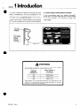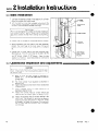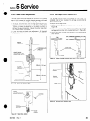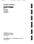
1
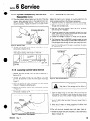
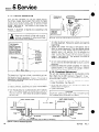
Service
Manual
30C, 55C, 80C Viewmast® LI
Triple Free-lift Roller Masts
Serial Numbers 658437 through 692673
Manual Number 667433 Rev. 1
cascade”
Cascade
is a Registered
Trademark
of
Cascade
Corporation
l
Viewmast
is a Registered
Trademark
of
Cascade
Corporation
I
4
0
Section
1 Introduction
This manual provides the installation instructions and maintenance, troubleshooting,
and service procedures for the
Cascade Viewmast® II a three-stage, full free-lift roller mast.
Viewmast® I I provides exceptional visibility for the lift truck
driver. The mast carriage and upright channels are all-roller
mounted, which results in smooth operation and long service
life. A unique, three-stage hoist cylinder provides fast operation
NAMEPLATE
and uniform lifting and lowering speeds of the carriage.
In any communication
about your Cascade Viewmast® I,
alwavs refer to the mast cataloq and serial numbers stamped
on the mast nameplate. If the-nameplate
is missing, these
numbers are also stamped on the left-hand side plate of the
upper crossbar.
/’
A WARNING
Do not install a Viewmast* I on a truck with a rated capacity
than the capacities shown by the accompanying chart.
CASCADE
VI EWMAST I I
greater
TRUCK CAPACITY
AT 24-INCH
LOAD CENTER
30C
3000 Pounds
55C
5500 Pounds
80C
8000 Pounds
Rated capacity of the truck/mast combination is a responsibility of the
orrginal truck manufacturer and may be less than shown on the mast
nameplate. Consult the truck nameplate.
667433
Rev. 1
1
Section
2 InstallationInstructions
2.1 Truck System Requirements
To achieve the maximum lifting capacity of the mast, the truck
relief valve should be set to relieve at the pressures indicated on
the chart below. This chart also indicates the hose and fitting size
to use between the truck control valve and the mast bootstrap
hose.
A
WARNING:
For proper truck stability or to
prevent interference, tilt restriction may be
required. Contact the truck manufacturer or
one of the Cascade Service Departments listed
on the back cover for the specific tilt
modification required. Note: To achieve the
proper tilt restriction, contact the lift truck
manufacturer, or your truck service manual.
Cascade
Viewmast
II
Minimum
Relief
Pressure
Maximum
Relief
Pressure
PSI
Hose
Sizes
Fitting
Thread
Sizes
#8
3/4-16
3OC Triple
1650 PSI
2000
55C Triple
1900 PSI
21OOPSI
#8
3/4-l
8OC Triple
1800 PSI
2200
#lO
718-14
PSI
6
IMPORTANT:
Standard
Viewmast® II masts are
compatible with SAE 1OW petroleum base oil per Mil.
Spec. M IL-O-5606 or MI L-02104 B only. Use of synthetic
or aqueous base hydraulic oil is not recommended. If fire
resistant hydraulic oil must be used, contact one of the
Cascade Service Departments listed on the back cover.
2.2
Mounting Bracket Installation
If it is necessary to install mounting brackets and crossmembers
to fit your truck, consult with the nearest Cascade Service
Department listed on the back cover. You must supply
drmensions A through F shown below in Figure 1. Failure to
Install the correct brackets and crossmembers can result in mast
structural failure, bodily injury and loss of warranty.
A
WARNING:
Failure to install the correct
brackets and crossmembers can result in
mast structural failure, bodily injury and loss of
warranty.
TRUCK
FRONT
Figure 1. Determining
2
Mounting
SIDE VIEW
VIEW
Bracket and Crossmember
COWL
Location.
667433
Rev.1
,
*
0
Section
2 InstallationInstructions
2.2 Mounting Bracket Installation (Cont.)
1. Mounting
bracket and crossmember
welding must be
performed by a qualified welder only, using the following
procedures:
a. Disassemble the outer channel from the mast prior to
welding. See Section 5.3-6 for disassembly procedures
b. Clean all surfaces to be welded. Remove paint, oil, grease
and other contaminants.
c. Locate the mounting brackets and crossmembers
mast channels.
on the
WARNING
Clamp in place with a “C” clamp. Protect the mast channel
inner surfaces from weld splatter.
d. Use only701 8 low hydrogen electrodes AWS E7018, 5/32”
diameter. Electrodes must be in good condition. Bake as
required to removeall moisture per electrode manufacturers
procedures
e. Use DC reverse polarity, or an AC welding machine. Set the
amperage at 175 amps.
f. Preheat the upright and mounting bracets to 100 F.
Montior with a Tempstick (crayon). Do not weld in a drafty
area.
Weld areas that will be vertical
seams when the mast is standing upright only.
DO NOT WELD ANY HORIZONTAL SEAMS.
WARNING:
g. Weld areas that will be vertical seams when the mast is
standing upright only. DO NOT WELD ANY HORIZONTAL
SEAMS. See Figure 2.
h. Weld the mounting brackets and crossmember with a .25
in. minimum fillet, holding a close arc. Weld in the flat
position only. Do not oscillate or use a wash bead pattern.
Make the weld in three passes. Let the weld slow cool.
WARNING
WELD ON VERTICAL
SEAMS ONLY.
I. Remove slag and inspect the weld. The following defects
are not allowed: undercut, overlap, stress cracks and
porosity. Clean the weld area and repaint with Cascade
paint part number 668209.
Figure 2.
Clamp Ground and Weld.
2. The measurement shown in Figure 3 should be taken after
welding and cooling the mast. This demenson must be
malntalned for the uprrghts to slide together.
3. Reassemble
the mast as described
TOP VIEW
in Section 5.3-8.
l-T===3
O”TE/R
E
4
UPRIGHT
MEASURE INSIDE TO INSIDE
OF OUTER UPRIGHT
AT TWO PLACES.
I
Figure 3.
667433
Rev. 1
Dimensional
Inspection
3
2 InstallationInstructions
Section
2.3
Mast Installation
1. Lubricate
mounting
2.
the bearing surfaces of the base and tilt cylinder
brackets with chassis grease.
7
Lift the mast by a link chain wrapped
twice around the
upper channel crossmembers.
Position the mast into place
on the lift truck and secure the base mountings.
HOSE
GUIDE
BOOTSTRAP
/HOSE
IMPORTANT
Prior
to connecting
the tilt
cylinders
to the mast, make sure
-
required to prevent
Refer to your truck
3. Connect
the tilt
the mast from “racking”
during
service manual for procedures.
cylinders
to the cylinder
anchor
HOSE CLAMP
tilting.
brackets.
&OUTER
UPRIGHT
4.
Before connecting
connect
the truck
actuate the control
oil.
the truck hose to the mast bootstrap,
hose to the truck
return
fitting
and
valve to flush the system with hydraulic
5. Connect
the lift truck
hose to the mast bootstrap
hose.
See Figure 4.
The lift truck
hose can be SA.E 100 R2
or R9. NOTE:
Use as few fittings as possible and always
use 45” elbows
instead of 90” elbows.
Keep the hose
lengths to a minimum.
when routing the hose.
2.4
Avoid
sharp
bends or pinch
LIFT TRUCK
. HOSE (FROM
TRUCK CONTROL
VALVE)
a-
points
Figure 4. Cylinder
and Truck Hose Connection
Operational Inspection and Adjustments
CAUTION
The factory
set adjustments
may not be correct for your
truck.
Check each of the following
before using the mast
for the first time.
q
Bleed air from
Section
5.1-7.
cylinder shell.
0
The hoist cylinder
Section 5.1-8.
0
Inspect the chains and check chain tension
in Section 5.4-l.
q
Check
crosshead
rollers for
described in Section 5.1-9.
0
Inspect
tracking
the cylinder
hose for correct
tension
and
over the rollers.
Refer to Section
5.3-13.
Inspect
the bootstrap
0
the mast cylinder
Do not use bleed
must
as described
in
screw on side of
sequence
as described
proper
hose for correct
in
as described
adjustment
tracking
as
in the
hose guides.
Adjustments
to the hose are made by
loosening the hose clamp shown in Figure 4. It may
be necessary to loosen the connector
fitting between
the lift truck hose and bootstrap
out the hoses.
hose to straighten
667433
Rev. 1
.
Section
3 Periodic Maintenance
For proper operation and an extended service life, your
Viewmast® II should be inspected and serviced regularly as part
of your normal lift truck maintenance schedule according to the
following outlines.
conditions or very corrosive atmospheres,
should be performed more frequently.
A
The recommended inspection intervals are for masts operating
under normal conditions. If the mast is operating in severe
these operations
WARNING: Never work on the mast with a load on
the forks orattachmentorwhileanyone
is nearthe lift
truck control handles.
Daily Inspection
3.1
Perform the following at the beginning
of each work shift:
1 Extend the carriaqe a few inches off the qround and make
sure the carriage-chains are under equartension.
Refer to
Section 5.4-l.
Extend themasttoitsfull
heighttomakesurethe
hoistcylinder
sequences properly.The primary plunger should extend fully,
then the master and slave plungers should extend together.
Make sure the mast channels and carriage extend freely
without binding. Refer to Section 5.1-8.
Cl Lower the mast and make sure the cylinder sequences
properly. The master and slave plungers should lower first,
then the primary plunger should lower. Make sure the mast
channels and carriage lower freely without binding. Refer to
Section 5.1-3.
’
While the mast is extended, inspect the upright channels for
proper lubrication. Refer to Section 5.3-8 step 1.
q
With the mast extended, make sure the hoist chains are under
equal tension. Refer to Section 5.4-l.
q
Make sure the cylinder hose is not twisted and is traveling
smoothly in the hose guides. Check the hose to besure it is not
scuffing. Minor adjustments to the hose can be made by
loosening the hose clampandtwisting
the hoseslightlytofit
in
the guides.
Be sure the urethane cushions at the base of the outer and
intermediate channels are not flattened or distorted.
Check crosshead roller clearance to assure proper operation
without binding. Refer to Section 5.1-9.
100 Hour Inspection
3.2
After each 100 hours of lift truck operation, in addition to the daily
Inspection:
0 Inspect and lubricate the full length of each pair of hoist
chains with SAE 40 oil.
CAUTION: The chains must be coated with a film of
lubricant at all times.
Zl Check each pair of hoist chains for wear and stretch. Refer to
Section 5.4.
3.3
500 Hour Inspection
After each 500 hours of lift truck operation. in addrtron to thedally
and 100 hour Inspection:
0 Check the clearances for load rollers. Refer to Section 5.3-l 2.
667433
Rev. 1
5
Section
4 Troubleshooting
The following table lists problems that.may be encountered on
your Quad Viewmast® II, the probable causes, and the recommended corrective action that should be taken to restore the
mast to normal operating condition.
NOTE: Any time oil is added to the truck
reservoir, check the hoist cylinder for possible
entrapment of air. Refer to Section 5.1-7.
SOLUTION
PROBLEM CAUSE
PROBLEM
.
Hoist cylinder doesn’t lift load
or won’t move-
. Empty
a)
a) Unplug hose or replace
Plugged inlet hose
b) Insufficient oil
b) Check truck hydraulic system for correct
oil level in tank, defective pump or pump
drive, leaks inthe lines or disconnected
control valve linkage. Repairor replace as
.-necessary.
c)
c) Replace defective plungers.
Bent or jammed plungers.
A WARNING: Extreme care should be used when working on a unit when the carriage
(with or without load) is in a raised position.
0 Loaded
a) Plugged piston check valve-master
may
a) Unplug check valve or replace.
b) Reversed piston check valve-master
may move.
b) reverse direction
arrow-up.
of check valve -
c) Truck relief setting low.
c) Raise truck relief setting to specified level.
Do not exceed: 30C - 2000 psi
55C-2100
psi
80C - 2200 psi
d) Over capacity.
d) Reduce load to specified capacity.
e) Mechanical bind due to bent plunger(s),
bad rollers and/or bad cross head rollers.
e) Remove mechanical bind by replacing/
freeing plungers and rollers.
A WARNING: Extreme care should be used when working on a unit when the carriage
(with or without load) is rn a raised position.
Mis-sequencing0 Empty or light load
Primary up - 1st
Slave up - 2nd
Master up -3rd, if at all.
0 Loaded
Prrmary up-l st
Master/Slave2nd
Slave stops short of full lift.
6
a) Sequence
rod adjusted too long.
b) Bent plungers.
a) Adjust sequence rod. (Turn clockwise.)
b) Repair or replace as necessary.
A WARNING: Extreme care should be used when working on a unit when the carriage
(with or without load) is in a raised position,
c) Master piston ball check not seating
properly.(Masterwill
moveduring primary
staae.)
c) Clean and/or replace piston ball check
assembly.
d) Master piston I.D. O-ring seal leaking.
(Master will move during primary stage.)
d) Replace C-ring and back-up ring
e) Relief valve defective. (Master will move
during primary stage.)
e) Replace relief valve-do
repair.
f) Master seal worn out. (Master will move
durina onmarv staae.)
f) Replace all cylinder seals.
9) Master prston check valve open.
9) Reolace check valve
h) Sequence rod out of adjustment. (Too
long.)
h) Adjust sequence
a) Piston sequence valve defective. (Master
will move during primary stage.)
a) Reparr or replace valve.
b) Master prston ball check not seating
properly.(Masterwill
moveduring primary
stage.)
b) Clean and/or replace piston ball check
assembly.
c) Master piston I.D. O-ring seal leaking.
(Master will move during primary stage.)
c) Replace O-ring and back-up rinq.
-
not adjust or
rod. (Clockwise,)
667433
Rev. 1
Section
4 Troubleshooting
,.
PROBLEM
0 Loaded (Continued)
SOLUTION
PROBLEM CAUSE
d) Master seal worn out. (Master will move
durina orimaw staae.)
d) Replace all cylinder seals.
e) Sequence
e) Adjust sequence rod. (Turn
counter-clockwised
rod stroke adjusted too short.
f) Repair or replace as necessary.
f) Bent plungers.
A
WARNING: Extreme care should be used when working on a unit when the carriage
(with or without load) is in a raised position.
0 Empty or loaded
Master up 1st-slow
Primary up-2nd (or during)
master)
Slave up-3rd
g) Check valve defective. (Open.)
g) Clean or replace as necessary.
h) Relief valve defective.(Master
times.)
h) Replace relief valve. Do not adjust or
repair.
moves at all
a) Relief valve open.
a) Replace relief valve - do not adjust or
repair.
a) External leak in pressure line.
a) Tighten or replace as necessary.
b) Truck valve defective-cycle
height to verifv.
b) Repair or replace truck valve.
Hoist cylinder driftsl
All plungers down
to full lift
c) External leaks at retainers.
c) Replace all cylinder seals.
0 Slave plunger down-Master
plunger up.
a) Relief valve defective.
a) Replace relief valve-do
repair.
b) Master piston check valve leaking.
b) Replace check valve.
Master plunger drifts up when
load is lifted, then stops.
(Approximately 1-2”.)
a) Air in cylinder.
a) Bleed air from cylinder
Spongy or jerky action.
a) Air in cylinder.
a) Bleed air from cylinder.
b) Sticky or defective truck relief valve.
b) Remove and check truck relief valve. If
contaminated oil caused the malfunctron
drain and flush the system, change the
filter, and refill with fresh oil.
A
WARNING: Extreme care should be
used when working on a unit when the
carriage (with or without load) is in a
raised position.
c) Bent or damaged
cylinder plunger(s).
c) Disassemble,
assembly.
not adjust or
check and repair cylrnder
A
WARNING: Extreme care should be used when working on a unit when the carriage
(with or without load) is in a raised posrtron.
d) Load rollers Improperly adjusted or
defective.
-
cl) Adjust or repair as necessary.
A
WARNING: Extreme care should be used when working on a unit when the carriage
(with or without load) is in a raised positron.
e) Mast channels improperly
lubricated.
e) Lubricate mast.
A WARNING: Extreme care should be used when working on a unit when the carriage
(with or without load) is in a raised position.
f) Low battery charge.
f) Charge battery.
g) Low pump volume.
g) Install accumulator.
h) Low oil level.
h) Fill oil reservoir and bleed cylinder,
i) Insufficient hydraulic tank capactty or
baffles.
i) Install larger tanks or baffles.
j)
j) Adjust sequence
improperly
k) Other.
667433
Rev. 1
sequencing
mast cylinder.
rod.
k) Contact Cascade Corporation.
7
.
Section
5 Service
5.1 Hoist Cylinder
5.1-l
Description
The hoist cylinder, shown in Figure 6, is a three-stage, displacement cylinder. It consists of a shell with three hollow, telescoping plunger assemblies, The slave plunger (smallest diameter)
telescopes into the primary plunger, and the primary plunger
telescopes into the master plunger (largest diameter).
The shell, master plunger, and primary plunger are threaded at
one end to receive retainers. A retainer is threaded into the
shell to limit the stroke of the master plunger. A retainer is
threaded onto the master plunger which secures an aluminum
bearing to limit the stroke of the primary plunger. A retainer
is threaded onto the primary plunger which secures an
aluminum bearing to limit the stroke of the slave plunger.
Each retainer has a Bi-Element seal assembly to provide a
high-pressure hydraulic
seal between the retainer and its
adjacent plunger. In addition, each retainer has a static (nonmoving) O-ring assembly and a plunger wiper.
A piston assembly is threaded onto the base of the master
plunger.
The piston has a Bi-Element seal assembly to
provide a high-pressure hydraulic seal between the piston and
the cylinder shell.
IMPORTANT:
During cylinder operation, the pressure produced in the cavity between the cylinder shell and the master
plunger is greater than that produced at the cylinder base
(truck pressure). Thus, the seal assembly on the master plunger
must be installed with the lip
piston
(item 35, Figure 6)
toward the plunger end of the cylinder.
spring that bears between the circular plate and the shoulder
of a special adjusting nut, threaded onto the upper end of the
rod. Access to the adjusting nut can be gained by removing
the bleed fitting threaded into a port at the top of the slave
plunger. To turn the nut, insert a 3/16-inch, long-handle,
Allen wrench. Refer to Section 5.1-8.
A lowering control valve is located at the supply port at the
base of the cylinder shell. It consists of a spacer, spring, and
special washer held in place by an elbow fitting threaded into
the port. The lowering control valve is a one-way flow limiter.
When the cylinder is extended, oil is free to flow unrestricted
around and through the special washer. However, when the
cylinder is lowered, the oil flow produced by the retracting
plungers forces the special washer toward the spacer. This
forces oil to flow through the orifice in the center of the
washer (as long as the washer is forced completely against the
spacer). This restriction allows the mast to lower at a controlled
speed, depending
upon the weight of the load.
5.1-2 Bi-Element
Seal Assembly
(Fig. 13)
The hoist cylinder assembly contains four Bi-Element seal
assemblies. See Figure 5. Each seal assembly is comprised of
a seal element and an anti-extrusion
element.
The seals are
used in combination with nylon back-up rings. The seals mus?
be installed in the cylinder assembly with the seal element
facing the highest pressure.
I
The master plunger piston also has a static O-ring seal to seal
between the piston and the master plunger.
A synthetic bearing is installed on the master plunger piston
and cast iron half-rings are installed at the base of the primary
and slave plungers.
The master plunger piston also serves as a housing for a poppetoperated check valve, a relief valve, and a sequence valve
assembly. The sequence valve assembly ensures the proper
sequencing of the cylinder plungers during extension and
retraction.
It is comprised of a spring-loaded ball and seat
assembly actuated by a spring-cushioned plunger. The sequence
valve plunger is actuated by a rod. The valve plunger is
attached to the rod at the rod’s lower end. The rod extends
through a square hole in the base of the primary plunger and
into the central cavity of the slave plunger and terminates near
the top of the slave plunger.
A spacer and circular plate are- installed at the top of the
sequence valve actuating rod. They are held in place by a
ANTI-EXTRUSION
ELEMENT
SEAL
ELEMENT
\
\
/
HIGHEST
PRESSURE
INSTALLED
Figure 5. Bi-Element
NOT
INSTALLED
Seal Assemblies
667433
Rev. 1
Rod Assy
Check
Valve
Assy.
Valve retaining washer (threaded)
39.
Bearing
O-ring plug
40.
Back-up ring
41.
Sequence valve plunger nut
O-ring
3.
Sequence valve plunger
42.
Primary plunger retainer
4.
Sequence valve plunger spring
43.
Seal
Relief valve
44.
Nylon ring
::
Spacer
Sequence
valve actuating rod
24.
25.
Relief valve O-ring
Primary plunger wiper
45.
26.
Primary plunger half-ring*
Bearing
46.
27.
Bearing
Slave plunger half-ring**
i:
Nylon ring
47.
Back-up ring
9.
Lowering control valve spacer
28.
Seal
O-ring
48.
29.
Lowering control valve spring
IO.
Sequence valve ball plug
Slave plunger retainer
49.
11.
Lowering control valve washer
30.
Sequence valve ball spring
50.
Seal
12.
Bleed screw
31.
Sequence valve ball spacer
Nylon ring
51.
13.
Bleed screw seal
32.
Sequence valve ball
Slave plunger wiper
14.
O-ring
33.
52.
Sequence valve rod plate
Bleed fitting
53.
15.
Back-up ring
34.
Sequence valve rod plate spring
Master pi unger piston
54.
16.
Master plunger retainer
35.
Sequence valve adjusting nut
Check valve poppet
55.
17.
Seal
36.
Adjusting nut cotter pin
Check valve
18.
Nylon ring
37.
Elbow fitting
E:
Check valve O-ring
19.
Master plunger wiper
38.
*‘3OC:
4 required with cylinders installed on all masts.
l 3OC: 2 required with cylinder installed on 68 and 74-inch masts;
4 required with cylinders installed on 80,86,92,98,104,
and
**55C:
2 required with cylinders installed on 68,74, and 80-inch masts;
11
11 l-inch masts.
4 required with cylinders installed on 83,92,101,107,114,119,
*5X:
2 required with cylinders installed on 68,74,80,
and 83-inct I masts;
124,129, and 134-inch masts.
4 required with yclinders installed on 92,101,107,114,119,
124,
**SOC: 4 required with cylinders installed on all masts.
129, and 134-inch masts.
“8OC: 4 required with cylinders installed on all masts.
21.
22.
23.
Master ~luncer
Primary plunger
Slave plunger
Figure 6. Exploded
667433
Rev.1
View of Hoist Cylinder
Assembly
9
Section
5 Service
5.1-3
Cylinder Operation
(Figure 7)
View A
The entire cylinder
assembly is filled with oil at the beginning
of its lifting sequence. Since the cylinder
is fully lowered, the
check valve is unseated by its actuating poppet in contact with
the base of the cylinder
shell. Since the sequence valve ball is
seated, oil in the cavity
between the cylinder
shell and the
master plunger (referred to as “sequencing
oil”) is trapped. The
master plunger
is thus prevented
from moving.
As a result,
when oil from the truck enters the cylinder
through
the inlet
port, it flows through
the angled port in the master plunger
piston and through
the unseated check valve to the primary
and slave plunger cavity.
View B
Since the area of the primary plunger piston is greater than that
of the slave plunger, the primary plunger begins to extend.
As
the primary
plunger
reaches the end of its stroke,
its base
contacts the spacer at the top of the sequence valve actuating
rod. Theactuating
rod thus shifts upward, pulling the sequence
valve plunger
upward
with it.
The sequence valve plunger
unseats the sequence valve ball. The point at which this event
occurs may be adjusted by turning the special adjusting nut at
the top of the sequence valve actuating rod.
View C
The trapped
sequence oil is at a pressure greater than that
from the truck.
(This pressure intensification
results because
the area of the piston that forms the cavity
between
the
cylinder
shell and the master plunger is less than the area of
the base of the master plunger piston. Remember that pressure
equals force divided by area. Since the area of the piston in the
sequence oil cavity is less, the pressure in the cavity is greater.)
Thus, as soon as the sequence valve ball is unseated, the previously
trapped
high-pressure
sequencing
oil flows past the
unseated sequence valve ball to the primary plunger cavity and
seats the unseated check valve. Oil from the truck can thus no
longer flow to the plunger cavities and truck pressure begins to
extend the master plunger.
View D
As the master plunger extends, the sequencing oil flows past
the unseated sequence valve ball and extends the slave plunger
from within
the extended
primary
plunger. This occurs until
the cylinder
is fully extended,
SLAVE
PLUNGER,
Srnce the volume of the sequencing oil cavity is nearly identical
to the volume of the slave plunger cavity,
master and slave
The volume
of oil
plungers
extend
at the same speed.
required
to lift the master plunger is approximately
twice that
required
to extend
the primary
plunger
(the first plunger to
extend),
Thus, the master plunger extends at half the speed
that the primary
plunger extended.
However, since the master
and slave plungers extend
simultaneously
at the same speed,
the combined speed of the master and slave plungers equals
the speed of the primary
plunger.
As a result, the cylinder
assembly extends (and lowers) at a constant speed throughout
its complete sequence of operation.
MASTER
PLUNGER
is included in the master
A relief valve (shown ln View C)
plunger
piston.
If the pressure of the sequencing
oil should
exceed a value preset by the relief valve, the valve will unseat
to allow pressure to be relieved to the base of the cylinder.
This could occur each time the cylinder
is extended
or when
excessive pressure build-up of thesequencing
oil, such as would
occure when the cylinder
is at rest, is heated by ambient air. A
check valve is located in the base of the slave plunger piston.
The check valvealiows
release of trapped oil which could occur
is oil leaks past the seal and gets caught between the piston
and retainer.
The lowering
sion.
10
VIEW A
of the
cylinder
assembly
is a reversal
PRIMARY
PLUNGER
\
\
\
SEQUENCING
01 L CAVITY
\
CYLINDER
SHELL
CHECK VALVE
(UNSEATED)
\
SEQUENCE
VALVE BALL
(SEATED)
\
INLET
PORT
’
3
CHECK VALVE’
POPPET
of extenlure 7. Hoist Cylinder Sequence of Operation
667433
Rev. 1
Section
5 Service
1
VIEW D
SLAVE
PLUNGER
VIEW C
SLAVE
PLUNGER
\
PRIMARY
PLUNGER
PRIMARY
PLUNGER
(FULLY
EXTENDED)
VIEW B
\
SLAVE
PLUNGER
k/
PRIMARY
/PLUNGER
MASTER
PLUNGER
d
\
CHECK
VALVE
(SEATED)
MASTER
PLUNGER
/
0
SEQUENCE
VALVI
BALL (UNSEATED
,ADJUSTlNG
NUT
,SPACER
SEQUENCE
#‘ACTUATING
VALVE
ROD
SEQUENCE
VALVE
BALL dUNSEATED
CYLINDER
-MASTER
PLUNGER
SEQUENCE
/PLUNGER
UPWARD)
/SEQUENCE
/
OIL
/SHELL
VALVE
(SHIFTED
,CHECK
VALVE
(SEATED1
‘MASTER
PLUNGER
PISTON
SEQUENCE
VALVE
BALL
(UNSEATED)
667433
Rev. 1
MASTEi
RELIEF
PLUNGER
VALVE
11
5 Service
Section
5.1-4
Cylinder Removal
1. Make sure the hoist cylinder
Iowered.
is fully
Always lubricate new seals,
O-rings, and wipers with petroleum
jelly or hydraulic oil prior to installation.
CAUTION:
SLAVE
PLUNGER-/
(
WARNING:
RETAINER
2. Loosen the bleed screw no more
1
than required to bleed off any hydraulic pressure that may remain in
the cylinder.
The bleed screw is
located on the side of the cylinder
shell just below the large piston re
tainer. Tighten the screw securely.
UJ
3. Remove the carriage according to
the removal procedures specified in
Carriage Section 5.2.
4. Remove the pad at the top of the
cylinder crosshead.
RETAINER
TORQUE
TO
100-150
FT.-LB.
-
BACK-UP RING*
MASTER PLUNGER
5. Remove the snap ring that retains
the crosshead assembly to the hoist
cylinder rod.
6. Remove the crosshead.
7. Wash the cylinder assembly with
solvent to remove any foreign material on the shell. Especially clean
around the plunger retainers. Blow
dry with compressed air. If you are
going to replace the seals, O-rings,
and/or wipers in the plunger retainers
only, you can do so with the cylinder
in place on the mast according to
the following
procedures (refer to
Figure 8).
a. Unthread
retainers.
the cylinder
(
:YLlNDER
THREADED
WASHER
TnRfll
.-..--- IF Tn
.40-50
FT.-LB.
1
FT.-LB.
55--70
BACK.UP
SHELL
5
II
I55C & 8OC)
L
I
17.5-g
FT.-LB.]
8. Remove
cylinder.
CHECK VALVE
SEAL*
1
\
RING*
/
150-55
INCLUDED
IN SERVICE
FT.-LB.
1
KIT
Figure 8. Hoist Cylinder Components
the bootstrap hose from the base of the
Be prepared to collect oil. Do not remove the
elbow fitting from the cylinder base. To gain access to
the hose fitting, you may have to lift the intermediate
channel upright high enough to expose the base of the
cylinder. Use another lift truck, hoist, crane, or some
other suitable lifting device.
12
O-RING*
NYLON
TO
*ITEMS
If you are going to replace components in addition
to those described above, the cylinder must be
removed from the mast. Continue
as follows.
RING*
LO-RING*
1
TORQUE
SCREWI
<-----J,BACK-UP
Do not remove any of
plungers.
c. Install the retainers as described
in section 5. 1-5 steps 12 through
15. Tighten all retainers to the
torque values shown in Figure 8.
A-BLEED
l3OC)
and remove all three
b. Replace the seals, O-rings, and/or
wipers in the retainers as required.
Carefully
note their positions
(see Figure 8).
Avoid excessive
stretching of the O-ring on the
large diameter retainer.
LY
RING*
9. Cap the fitting at the base of the cylinder with a highpressure steel cap (a plastic cap will not afford sufficient
protection to the threads if the fitting is “banged” during
cylinder removal). Plug the bootstrap hose.
10. Using a lifting strap and hoist, remove the cylinder
the mast.
11. Lay the completely
NOTE:
collapsed cylinder
from
on 4 X 4’s.
Cut 2 (two) 2” deep U-Cuts in each 4 X 4.
667433
Rev.
1
0
Service
Section 5
5.1-5 Cylinder Disassembly, Service and Reassembly
1. Use a claw type spanner wrench to unthread
plunger retainer. (Item 16, Figure 6.)
the master
2. Slide the master, primary, and slave plungers out of the
cylinder shell as an assembly.
3. Remove the seal and nylon ring from the piston at the base
of the master plunger using the following procedures. Be
careful not to scratch the seal groove diameter.
a. Pry the seal up from its groove with a dull screwdriver.
b. Cut the seal off the piston groove with wirecutters or a
knife. Make sure the knife does not scratch the groove
or the plunger.
b. Remove the nut retaining the sequence valve plunger and
spring. Remove the sequence valve plunger and spring.
See Figure 9.
c. Depress the sequence valve plug protruding through a
hole near the base of the master plunger with a screwdriver or a punch. Then,-using a spanner wrench in the
holes provided in the piston, unthread and remove the
piston from the plunger. See Figure 10. You may need a
helper to hold the plunger with a strap wrench. When
you have turned the piston the first 180°, use your
screwdriver or punch to prevent the sequence valve plug
1
SCREWDRIVER
c. Remove the nylon ring.
IMPORTANT
When cylinder components are disassembled and seals,
O-rings, and wipers are removed, thoroughly
wash all
metallic parts in solvent. Blow dry with compressed air.
Carefully inspect the plungers, cylinder bore, piston, and
disassembled valve components.
Replace if seriously
scored, grooved, pitted, or worn. Minor damage to the
cylinder bore and plungers can be removed with 400 grit
polishing cloth (wash after polishing). Place components
in a clean container until reassembly.
4. Install the new seal and back-up ring on the piston, carefully
Avoid excessive
noting their position
(see Figure 8).
stretching of the seal. Using a lubricant such as STP or
hydraulic oil will ease seal installation.
MASTER
PLUNGER
WRENCH
\STRAP
/’
Figure 10.
WRENCH
Removing the Piston from the Master Plunger
5. Replace the bearing on the piston at the base of the master
plunger.
from snapping into the
hole on the other side of. the
plunger. Be prepared to catch the sequence valve plug,
spring, spacer, and ball when the plug clears the plunger.
6. Remove the relief valve located on the bottom of the master
olunger piston. See Figure 9. It is recommended that the
relief valve be replaced. Tighten to a torque of 15-20 ft.-lbs.
d. Replace the O-ring and back-up ring on the piston, carefully noting their position. See Figure 8. Avoid excessive stretching of the O-ring during installatron.
7. If vou are aoina
- to replace the check valve and/or the 0-rino
and back-up ring between the master piston and its plunger,
do so now according to the following procedures. If any of
these components are not to be replaced, proceed to Step 8.
e. If you are not going to replace the check valve, proceed
to Step g.
a. Remove the O-ring plug from
piston.
See Figure 9.
MASTER
the base of the master
PLUNGER
-4
MASTER
PISTON
If you are going to replace the check valve, remove the
threaded washer retaining the valve. The washer is staked
in one place. Remove the valve. (If the poppet behind
the valve falls out, it is symmetrical and can be reinstalled
either way.) Replace the check valve using a new O-ring.
See Figure 11.
THREADED
WASHER
PLUNGER
SEQUENCE
VALVE PLUNGER
SPRING
CHECK
VALVE
’
+J
PISTON
POPPET
awe 9. Sequence Valve Plunger Assembly and Relict Valve
667433
Rev. 1
13
5 Service
Section
5.1-5
Cylinder Disassembly,
Reassembly (Cont.)
Service and
PLACE THE
IMPORTANT
PISTON
IN THE CYLINDER
LOADER
SHELL.
Make sure you install the check valve with the arrow
(stamped on the valve body) pointing toward the rod end
f.
Install and torque the threaded washer to 40-50 ft.-lb.
(30C), 65-70 ft.-lb. (55C and 80C).
See Figure 8.
Stake the washer in place to secure it.
NOT ALLOW
CYLINDER
g. Assemble the sequence valve ball, ball spacer, spring, and
plug in place onto the master plunger as shown in Figure
12. Then thread the piston onto the master plunger. As
the piston is threaded on, the sequence valve plug will
snap into one of the two holes in the plunger. With a
LOWER
GE OF LOADER
TO
PISTON
BALL SPACER
SPRING
PLUG
igure 12. Sequence Valve Ball Assembly
screwdriver or punch, push the plug in and keep turning
the piston until it seats. Then back off no more than 1/2
turn until the plug snaps into one of the holes. Use the
tools and procedures shown in Figure 10.
h. install the sequence valve plunger spring and plunger in
the hole in the base of the master piston. See Figure 13.
Install and torque the retaining nut to 7.5-9 ft.-lb.
&PPLY A THICK
FILM
3F PETROLEUM
JELLY.
Figure 14.
9. Slide the master/primary/slave
plunger assembly all the way
into the cylinder shell but don’t tighten the large-diameter
retainer. See Figure 14.
10. Unthread and remove the upper two retainers, then remove
the large-diameter retainer.
Do not remove any of the
cylinder
i.
Install the O-ring plug and torque to 50-55 ft.-lb. See
Figure 13. Figure 13 illustrates the correct orientation
of the sequence valve components when the piston is
assembled onto the master plunger.
I
MASTER
PLUNGER
--I
I
PLUG
SEQUENCE
VALVE
PLUNGER
SPRING
Master Plunger Loader
plungers.
11. Replace the seals, o-rings and wipers in the retainers.
Lubricate the new seals with petroleum iellv orior to installation
Note the correct seal locations. See Figure 8. Avoid
excessive stretching of the o-ring on the large-diameter
retainer.
12. Place the second largest retainer loader over the end of the
master plunger.
Apply petroleum jelly to the loader and
inner surface of the master plunger retainer.
Load the retainer onto the master plunger then remove the loader.
Tighten the retainer to a torque of 200-250
ft.-lbs.
See Figure 15.
’
BALL
SPACER
BALL’
MASTER
PISTON
/
PLUNGER
Figure 13. Sequence Valve Assembly,
Master Plunger
Located at the Base of the
8. Place the largest diameter piston loader in
See Figure 14. The loader must cover all
not contact the thread relief chamfer. The
fins can be trimmed with a sharp knife if
is needed. The piston will not enter the
contacts the thread relief chamfer. Apply
the master plunger seals and loader I.D.
14
-.
the cylinder shell.
of the threads but
length of the stop
more engagement
shell if the loader
petroleum jelly to
---
.
.
.
13. Place the third largest retainer loader over the end of
primary plunger. Apply petroleum jelly to the loader
inner surface of the primary plunger retainer.
Load
retainer onto the primary plunger. Tighten the retainer
torque of 100-150 ft.-lbs. See Figure 15.
667433
the
and
the
to a
Rev. 1
,
Section
5 Service
5.1-5
Cylinder Disassembly,
Reassembly (Cont.)
5.1-7
Service and
Bleeding the Cylinder
Before the mast is put in service, air must be bled from the
hoist cylinder according to the following procedures.
14. Place the smallest retainer loader over the end of the slave
plunger. Apply petroleum jelly to the loader and inner surface of the slave plunger retainer. Load the retainer onto
the slave plunqer. Tighten the retainer to a torque of I00150 ft.-lbs. See Figure 16.
1. Assemble the forks (or attachment)
onto the mast carriage.
2. Without a load on the forks, extend and retract the mast
through one complete cycle.
3. With the mast fully lowered,
tank and top off if necessary.
check the truck
hydraulic
4. Extend and retract the mast completely at least four more
times. This action will force air in the system to the cylinder
center cavity under the bleed fitting.
SLA
PLUNGER
Flgure 16.
Retamer
5. Extend
the carriage to about
10 inches off the ground.
6. The Customer User Kit (661506) includes a metal hex tube
wrench (661507) and a length of clear plastic hose (661922).
Slide the plastic hose through the hex tube wrench and onto
the bleed fitting located at the top of the cylinder crosshead. Put the other end of the tube in a container to collect
oil. See Figure 18.
Loader
15. Reinstall the cylinder to the mast by reversing the removal
instructions in Section 5.1-4.
CLEAR PLASTIC
HOSE 661922
.
CAUTION:
Be sure the cylinder is properly seated in the
mast support casting, with the pin in the hole.
HEX TUBE
”
WRENCH
CYLINDER
J
MAST
SUPPORT
ICASTING
.030” TYP.
5.1-6
Lowering Control Valve Service
1. Remove the hoist cylinder
Section 5.1-4.
from the mast as specified
in
2. Remove the elbow fitting from the base of the hoist
cylinder. Be prepared to catch the valve spacer and spring.
Remove the lowering control valve special washer. See
Figure 17.
3. Clean and inspect the valve components
inlet port. Replace any defective parts.
4. Replace the lowering
in Figure 17..
control
and the cylinder
valve components
as shown
5. Reinstall the cylinder to the mast by reversing the removal
instructions in Section 5.1-4.
HOIST
TO CONTAINER
I
I
I
CYLINDER
BASE
,,
1
Figure 18.
Hoist Cylinder
A
Bleed Kit
WARNING
Stay clear of the carriage ana the forks or
attachment.
7. Open the bleed fitting no more than 1/4 turn with the hex
tube wrench. The weight of the carriage will force air and
hydraulic oil out of the cylinder through the bleed fitting.
8. If the carriage reaches the bottom of its travel before all
the air is bled, close the bleed fitting and repeat Steps 5
through 7.
SPECIAL
9. When the oil stream no longer contains air bubbles, close
the bleed fitting and torque to 25-27 ft.-lb.
10.Top
’
Figure 17.
667433
ELBOW
FITTING
Lowering Control Valve Assembly
Rev. 1
off
the truck
hydraulic
tank with
clean, fresh oil.
11. Extend and retract the mast completely. If the mast doesn’t
operate smoothly or if it appears to be “spongy”, repeat
Steps 2 through 10.
15
Section
.
5 Service
5.1-8
+
Cylinder Sequencing
CROSSHEAD
When the mast is actuated from the fully lowered position,
the primary plunger should extend from within the master
plunger to the end of its stroke. Then the master and slave
plungers should extend simultaneously
to the end of their
See Figure 19. The lowering of the plungers is a
strokes.
reversal of extension.
However,
following
if adjustment
procedures.
A
is required,
do so according
1 1 BOTTOMS
the forks or attachment, or while anyone is near
the lift truck control handles.
Figure 20.
I
1.v
J
Turning the Adjusting
Nut Counterclockwise
5. Operate the cylinder with about a half-capacity
load to
check for proper sequencing. If the slave plunger extends
too fast and the master plunger does not extend at all, the
sequence valve is not opening. Turn the adjusting nut
clockwise one turn only. Reinstall the bleed fitting and
retest. Continue this process until the cylinder sequences
properly.
See Figure 19. The adjusting nut should be
turned 10 turns maximum.
SLAVE
PLUNGER
k-
MASTER
PLUNGER
6. As soon as the cylinder sequences properly, turn the adjusting nut clockwise one more turn only to assure a positive
adjustment.
CYLINDER
/SHELL
7. Extend and retract the cylinder completely. If it does not
operate smoothly or if it appears to be “spongy”, bleed air
from the cylinder as specified in Section 5.1-7.
:I-
5.1-9
Sequence of Hoist Cylinder Plunger Extension
The sequencing of the hoist cylinder is controlled by an interna’ sequence valve. The sequence valve is preset at the factory
and should not require adjustment.
However, if the cylinder IS
disassembled, the sequence valve can be adjusted according to
the following procedures.
1. Remove the bleed fitting
at the top of the slave plunger.
2. Insert a 3/l 6-inch, long-handle, hex socket wrench 662611
into the bleed hole and engage the adjusting nut.
3. Turn the adjusting nut counterclockwise
until it bottoms.
The nut is crimped slightly to prevent free-turning so it
may be a little stiff. Don’t force the nut after it bottoms.
See Figure 20.
,MAST
1
1
4. Turn the adjusting nut clockwise two full turns to provide
an initial adjustment. Remove the wrench and install the
bleed fitting.
PRIMARY
PLUNGER
I
WRENCH
to the
WARNING
Never work on the hoist cylinder with a load on
THE PRIMARY
PLUNGER
SHOULD
EXTEND
FIRST, THEN THE
MASTER AND
SLAVE PLUNGERS
Figure 19.
HEX SOCKET
Crosshead Adjustment
The sum total clearance between the tire shoulders and the
Mast I-Beam must be .060” as shown in Figure 21. If one
tire is touching the I-Beam (which is acceptable) the other tire
should have .060” clearance.
Adjust the Crosshead to attain the clearance
1. Loosen the setscrew. See Figure 21.
as follows.
2. Use an open end wrench to turn the hex nut to attain the
clearance shown in Figure 21.
3. Tighten the setscrew.
CAUTION
Insufficient tightening can result in the tire loosening
the crosshead jamming between the I-Beams.
MAST
I-BEAM FLANGE
I-BEAM
FLANGE
and
I
\
A + B = .060”
UIDE
SETSCREW
CAUTION:
Figure 21.
16
The tire should never touch the guide at these points.
Triple Lift Crosshead Adjustment
667433
Rev. 1
.
Section
0
5.2
5 Service
Carriage
5.1-1
Description
5.2-2
The carriage, shown in Figure 22, is the structure to which
hook-type forks or the attachment is attached. The carriage
travels within the channels of the mast inner upright on six,
shim-adjustable load rollers. The two upper load rollers are
secured to their stub shafts by keepers; the four lower load
rollers are held in place by the inner channel when the carriage
is assembled onto the mast. All six load rollers are interchangeable. A pair of non-adjustable
chain anchors are used to
connect the carriage chains to the carriage.
/CARRIAGE
Carriage Removal
The carriage may be removed with the mast installed on ‘the
truck according to the following procedures.
1. Block the carriage off the ground and lower the mast to
slacken the carriage chains. Connect a sling to the carriage
and secure it with some suitable lifting device.
2. Remove the snap rings that retain the chain anchors to the
carriage lower fork bar. Remove the chain anchors.
WELDMENT
NOTE: Stub shafts are replaceable
per Technical Bulletin 126.
ROLLER
SHIM
(QTY. AS REQUIRED)
ROLLER
(6 REQUIRED)
KEEPER
SHIM
KEEPER
/
/
(QTY.
AS REQUIRED)
(2 REQUIRED)
CAPSCREW
(4 REQ’D.)
(2 REQ’D.)
CARRIAGE
HOIST CHAIN
lure zz.
667433
The
Carriage
Rev. 1
Assembly
17
5 Service
Section
5.2-2
Carriage
Removal (Cont.)
3. Back out
the two carriage stop screw assemblies. A stop
screw assembly is comprised
of a nut welded to a sockethead capscrew.
See Figure 23. By backing out the nut that
extends through the carriage side plate, the socket head of
the screw will clear the stop block on the inner channel up
right. You may have to extend the carriage to gain access to
the stop screw assemblies.
4. Power the hoist cylinder
to extend until the inner upright
channel
clears the carriage
load rollers.
Back the truck
away from the carriage. (If the hoist cylinder is inoperative,
raise the inner uoriaht channel with a hoist. crane, or some
other suitable lifting device.)
l
Check
strands
l
Check for
show signs
anchors,or
If wear is
l
Check for worn,
Replace or adjust
5.2-4
I,
CARRIAGE
SIDE
PLATE
for
protruding
of chains.
or
turned
pins.
Replace
both
chain side wear. If pins and outside
plates
of wear, check for misalignment
of sheaves,
other components.
Correct the misalignment.
excessive,
replace
both strands of chains.
broken,
or
as required.
misaligned
chain
anchors.
Carriage Installation
(with the mast installed on the truck)
Make sure the inner upright
channel
with chassis lube or Kendall
599474).
See Figure 24.
members
SR-12X
are lubricated
(Cascade part number
STOP
BLOCK
ION INNER
CARRIAGESTOP SCREW
ASSEMBLY
INNER
UPRIGHT
CHANNEL
-0AD
/
ROLLER
LUBRICATE
I-lgore Z3.
Carnage Stop Screw Assembly
INDICATED
BY THE
HEAVY
LINE
5.2-3
Cleaning and Inspection
3. Inspect the roller bearings by turning
the rollers on their
shafts.
Roller
assemblies
with
roughness
or noticeable
restrictlons
to turning should be replaced.
4. Inspect all welds between
the carriage side plates
carriage fork bars, If any weld seams are cracked,
the carriage.
and the
replace
6. Inspect the carriage hoist chains. If inspection
reveals that
one strand of a pair of chains requires replacement,
both
strands of the pair should be replaced.
Check for rust and corrosion.
l
Check
plates,
for cracked side plates. If you
replace both strands of chains.
l
Check
for
tight
joints.
or corrosion, loosen
oil. If they cannot
caused by bent pins
replace both strands
18
If tight
joints
find
igure 24.
cracked
3. With a sling, position
blocks in front
of the
by
them with SAE 30 oil or penetrating
be loosened
or if tight joints are
or plates or by peened plate edges,
of chains,
the carriage
mast.
assembly
in place
on
5. Lift the carriage the full length of the inner upright channel
and check side play and freedom of movement.
Adjust load
roller clearance as specified in step 2.
6. Thread
Tighten
in the carriage stop screw assemblies.
to a torque of 100-110
ft.-l bs.
CAUTION:
can cause
side
rust
(typical)
Raise the inner upright
sufficiently
for the carriage load
rollersto
be fitted within the inner upright channels.
Lower
the inner upright over the carriage.
7. Install
are caused
Mast Lubrication
FULL
OF EACH
2. Assemble
the load rollers onto their stub shafts using an
appropriate
number of shims.
See Figure 22.
The shims
should be installed to provide
a total clearance no looser
than 0.030 inch at the tightest point throughout
the travel
Refer to Section
5.3-12 for load roller
of the carriage.
shimming.
4.
5. Inspect the stub shafts. If they are damaged or if there are
cracks at the base of the stub shafts, the carriage must be
replaced or repaired.
Refer to Technical
Bulletin
126 for
stub shaft replacement.
l
FOR THE
LENGTH
1. Remove the load rollers and thoroughly
clean the carriage
assembly with cleaning solvent. Note the number of shims
on the rollers so that an appropriate
number of shims can
be installed during reassembly.
2. Inspect the rollers for excessive wear or damage. Roller
assemblies
with
visible
flat
spots or cracks should
be
replaced.
ONLY
WHERE
8.
Lower
Failure to thread in the stop screw assemblies
the mast uprights
to sequence
incorrectly.
the carriage
the
as shown
See Figure 41,
hoist chains.
carriage. and check
in paragraph 5.2-5.
9. Check the total freedom
scribed in Section 5.3-10,
and adjust
of the
step 7.
carriage
the
load
movement
667433
chains
as de-
Rev. 1
Section
5 Service
5.2-5
Carriage Chain Adjustment
The carriage hoist chains should be adjusted so that when the
unloaded mast is fully lowered, the carriage is positioned as
shown in Figure 25.
To adjust the carriage chains:
1. Locate the carriage chain anchors on the inner upright.
Figure 26.
See
CARRIAGECHAIN
2. Adjust one carriage chain anchor nut to achieve the correct
carriage position when fully lowered as shown in Figure 25.
3. Adjust the other carriage chain anchor nut to achieve equal
chain tension.
5-IN.
3 IN.
UNDERCLEARANCE
6-IN.
UNDERCLEARANCE,
OR
UNDERCLEARANCE,
A=2
IN
A=3
IN
CHAIN
ANCHOR
NUT
Figure 25.
5.3
Correct
Carriage Positions when Mast is Fully Lowered
Figure 26.
-
-
I
I
Carriage Chain Adjusting Nut
Mast Upright Assembly
5.3-1
Upright Description
The Cascade Viewmast®
II is comprised of three upright
assemblies: outer, intermediate, and inner. See Figure 27.
1. Outer Upright Assemblv
The outer upright assembly is mounted to the truck. A pair
of shim-adjustable load rollers is attached to canted stub
shafts located near the top of the upright. A pair of
urethane cushions is attached to the lower crossmember to
cushion the intermediate
upright when the mast is fully
lowered. A pair of non-adjustable chain anchors is located
near the top of the upright to which the bootstrap hoist
chains are attached.
2. Intermediate
Upright Assembly
The intermediate
upright assembly telescopes within the
outer upright assembly. A pair of shim-adjustable
load
rollers is attached to canted stub shafts near the top of the
upright and a pair is attached near the bottom of the upright. In addition, a pair of chain sheaves is located near the
bottom of the intermediate
upright to provide a rolling
surface for the bootstrap hoist chain.
667433
Rev. 1
A pair of bushing blocksare bolted to steel blocks welded on
both sides of the upright near the bottom.
The bushing
blocks stabilize the intermediate upright assembly when the
mast is extended and tilted back. A cushion is attached to
the intermediate upright lower crossmember to cushion the
inner upright when the mast is fully lowered.
The hoist
cylinder rests on a cradle which is integral with the lower
crossmember of the intermediate upright assembly.
3. Inner Upright Assemblv
The inner upright assembly telescopes within the intermediate upright assembly. A pair of shim-adjustable load
rollers is attached to canted stub shafts near the bottom of
the assembly. A pair of adjustable chain anchors is located
near the bottom of the inner upright assembly to which the
bootstrap hoist chains are attached. In addition, a pair of
adjustable chain anchors is located on the lower crossmember of the inner upright to which the carriage hoist chains
are attached.
4. Mast Operation
Figure 28 illustrates the operation of the Cascade Viewmast®lL
19
5 Service
Section
OUTER
NOTE: Upright stub shafts are replaceable
per Technical Bulletin 126.
INTERMEDIATE
INNEk
UPRIGHT
1.
2.
3.
4.
5.
6.
7.
8.
9.
IO.
Figure 27.
20
Exploded
Roller (8 required1
Shim
Chain anchor block (2 required)
Capscrew (4 required)
Lockwasher (4 required)
Dowel pin (2 required)
Chain anchor (4 required)
Nut (4 required)
Cotter pin (4 required)
Pin (6 required)
11. Cotter pin (I 2 required)
12. intermediate upright cushion
13. Capscrew (6 required)
14. Outer upright cushion (2 required)
15. Sheave (2 required)
16. Snap ring (2 required)
17. Bootstrap hoist chain (2 required)
18. Bushing blocks (2 required)
19. Capscrew (2 required)
20. Lockwasher (6 required)
View of Mast Upright Assembly
667433
Rev. 1
5 Service
Section
0
5.3-1
Upright Description (Cont.)
CARRIAGE
Iv
LIFTING
PAD
CARRIAGE
INTERMEDIATE
UPRIGHT
CARRIAGE
CHAIN
OUTER
/
BOOTSTRAP
HOIST CHAIN
INTERMEDIATE
UPRIGHT
CROSSHEAD
LIFTING PAD
u
I
I
INTERMEDIATE
/
UPRIGHT SHEAVES
A.
FULLY
LOWERED
The carriage chains are anchored to the inner upright.
They are looped around the
crosshead sheaves and attached
to the carriage.
The bootstrap chains are anchored to the top of the outer
upright. They are looped around the intermediate upright
sheaves and attached
to the
inner upright.
The hoist cylinder shell rests
on a cradle which is integral
with the lower crossmember of
the Intermediate upright.
B.
FREE-LIFT
When the hoist cylinder
is
powered from the fully lowered
position, the carriage is drawn
upward within the inner upright at a speed twice that of
the hoist cylinder. The freelift portion of the extending
sequence ends when the crosshead lifting pad contacts the
upper crossmember of the inner upright.
C.
FULLY
EXTENDED
Continued
hoist cylinder extension causes the inner upright and carriage to be drawn
upward with the crosshead lifting pad. The extending inner
upright also causes the bootstrap chains to draw the intermediate upright and hoist cylinder shell upward. The speed
of the extending intermediate
upright is half that of the inner
upright.
Thus phase of mast extension
continues until the mast IS fully
extended.
(The sequencing of
the hoist cylinder is independent of mast operation; that is,
the master plunger does not
necessarily reach the end of
its stroke at the end of the
free-lift
portion
of mast extensron.
The lowering of the mast is a
reversal of extension.
Figure 28.
667433
Mast Operation
Rev. 1
21
5 Service
Section
5.3-2
Crosshead Description
The crosshead, shown in Figure 29, is attached to the top of
the hoist cylinder. Rollers attached to the crosshead move
‘within guides on the inner upright assembly to guide the hoist
cylinder as it extends and retracts. A pair of chain sheaves
attached to the crosshead provide a rolling surface for the
carriage hoist chains.
HOSE
GUIDE
BOOTSTRAP
HOSE
CAPSCREW
TORQUE
TO 6-7
\
FT.-LB.
HOSE CLAMP
LOCKWASHER
_ LIFTING
PAD
P
/
SETSCREW
/
,’
I
NYLON
PELLET
I I
I-
OUTER
UPRIGHT
m
\
I
iR
---JRkh’lll
i
CROSSHEAD
CHAIN
L
SHEAVE
MARKED
Fi gure 30.
ROLLER
5.3-3
I
ASSEMBLY
Crosshead Assembly
Mast Removal
A
WARNING
Never work on the mast with a load on the
forks or attachment or while anyone is near
the lift truck control handles.
1. Make sure the mast is fully lowered. Make sure the mast is
straight up (not tilted forward or backward).
2
Rear View of Mast Assembly
6. Disconnect
brackets.
“OUTSIDE”
SNAP RING ’
Figure 29.
‘I-AUXILIARY
JUMPER HOSE
IBETWEEN
TRUCK
CONTROL
VALVE
AND
BOOTSTRAP
HOSE
Remove the forks or attachment from the mast carriage.
Remove any auxiliary equipment that would interfere with
mast removal.
the tilt
cylinders from the tilt cylinder
7. Disconnect the mast base mounting
anchor
brackets.
8. Lift off the mast and set it on a work surface with the
carriage up. If the mast is equipped with a hose reel, block
under the mast sufficiently to clear the reel, or remove the
reel. Make sure the mast assembly does not rest on the
bootstrap hose guides. Remove the hose guides if necessary.
5.3-4
Carriage Removal
(with mast removed from the truck)
1. Connect a sling to the carriage and secure it with
suitable lifting device.
some
2. Remove the pins that secure the carriage hoist chains to the
chain anchors located on the lower fork bar. See Figure 31,
CARRIAGE
HOIST CHAI
3. Remove the truck auxiliary hose from the hoist cylinder
bootstrap hose. See Figure 30. Be prepared to collect oil.
Plug the bootstrap hose and cap the truck auxiliary hose.
4. Loosen the hoist cylinder bteed screw no more than
required to bleed off any hydraulic pressure that may
remain in the cylinder. The bleed screw is located on the
cylinder shell just below the largest piston retainer. Tighten
the screw.
5. Wrap a link chain twice (minimum) around the three upper.
mast channel crossmembers and secure with a hoist, crane,
or some other suitable lifting device.
22
CHAIN
ANCHOR
’ COTTER
PIN
Figure 31.
Carriage Hoist Chain Anchor
667433
Rev. 1
.
,
5 Service
Section
5.3-4
Carriage Removal (Cont.)
(with mast removed from the truck)
5.3-6
Upright Disassembly
(with mast removed from the truck)
Refer to Figure 34.
3. Unthread the two carriage stop screw assemblies. A stop
screw assembly is comprised of a nut welded to a socket-.
head capscrew. See Figure 32. By backing out the nut that
extends through the carriage side plate, the socket head of
the screw will clear the stop block on the inner channel
upright.
Disassembly of the mast uprights with the mast mounted on the truck
is NOT recommended.
A
WARNING:
’
1. Remove the carriage and hoist cylinder.
5.3-4 and 5.3-5.
-
Refer to Sections
2. Manually extend the mast until the bootstrap
anchor blocks on the inner upright are exposed.
3. Remove the pins that secure the bootstrap
the chain anchors on the inner upright.
hoist chain
hoist chains to
4. Remove the bootstrap chain anchors from the inner upright.
STOP
BLOCK
ION INNER
CHANNEL)
CARRIAGESTOP SCREW
ASSEMBLY
lr
-I-
i
INNER
UPRIGHT
CHANNEL
5. Roll the inner upright toward the top of the mast until the
inner upright load rollers are exposed by the cutouts at the
top of the intermediate upright.
6. Using a sling and hoist or some other appropriate
lifting
device, lift the inner upright out of the intermediate upright
and set it on a work surface.
7. Roll
until
outs
hoist
the intermediate upright toward the top of the mast
the intermediate load rollers are exposed by the cutat the top of the outer upright. Pull on the bootstrap
chains to keep them straight.
CAUTION:
Pull on the bootstrap
hoist chains to keep them
straight.
Figure 32.
8. Using a sling and hoist or someother suitable lifting device,
lift the intermediate upright out of the outer upright. As
soon as the chain sheaves at the bottom of the intermediate
upright are clear of the outer upright cutouts, pull the
bootstrap hoist chains off the sheaves. ‘See figure 33. Set
the intermediate upright on a work surface.
Carriage Stop Screw Assembly
4. With the lifting device secured to the carriage, remove the
carriage out the bottom of the mast assembly.
9. Remove the bootstrap
chain anchors.
5. Remove the carriage hoist chains from the inner upright
lower crossmember.
hoist chains from the outer upright
INTERMEDIATE
UPRIGHT
6. For carriage cleaning and inspection, refer to Section 5.2-3.
\
5.3-5
Crosshead and Cylinder Removal
(with mast removed from the truck)
the bootstrap hose from the base of the hoist
Be prepared to collect oil. Do not remove the
elbow fitting from the cylinder base. Cap the fitting with a
high-pressure steel cap (a plastic cap will not afford sufficient protection to the threads if the fitting is “banged”
during cylinder removal).
INTERMEDIATE
UPRIGHT
CHAIN
SHEAVE
INTERMEDIATE
UPRIGHT
LOAD
ROLLER
1. Remove
cylinder.
------
2. Connect a sling around the hoist cylinder and secure it with
some suitable lifting device.
3. Remove .the pad at the top of the cylinder
crosshead.
4. Pull the carriage hoist chains through the crosshead sheaves.
5. Remove the snap ring that retains the crosshead assembly
to the hoist cylinder
rod and remove the crosshead.
6. With the lifting
from the mast.
device secured to the sling, lift the cylinder
7. For cylinder service, refer to Section 5.1.
667433
Rev.1
OUTER
Figure 33.
UPRIGHT
Bootstrap
Hoist Chain Routing
23
Section
5.3-7
5 Service
Cleaning and Inspection
1. Remove the load rollers and chain sheaves from the up
rights, carriage, and crosshead. Note the number of shims
on the rollers so that an appropriate number of shims can
be installed during reassembly.
4. Inspect the load rollers and chain sheaves. Roller and
sheave assemblies with visible flat spots, excessive wear, or
cracks should be replaced.
crosshead
5. Inspect the load roller and chain sheave bearings by turning
them on a shaft. Roller and sheave assemblies with roughnessor noticeable restrictions to turning should be replaced.
3. Inspect the rolling surfaces of the upright channels. Excessive wear, grooves, or scoring could be the result of faulty
load rollers and/or improper mast lubrication.
6. Inspect the rollers on the crosshead. If they do not turn
freely or are damaged or excessively worn, replace the roller
assemblies.
Torclue the roller nut to 30-35
ft.-lbs.
2. Thoroughly
clean the upright,
assemblies with cleaning solvent.
carriage,
and
HO~STC;~~c~
BOOTSTRAP
INTERMEDIATE
UPRIGHT
INTERMEDIATE
UPRIGHT
CUTOUT
INNER UPRIGHT
-ROLLER
d.P-iY
COTTER
PIN
ANCHORS
COTTER
PIN
BOOTSTRAP
CHAIN
ANCHOR
Figure 34.
24
667433
Rev. 1
,
Section
5.3-7
5 Service
Cleaning and inspection (Cont.)
7. Inspect the stub shafts. An assembly with a damaged stub
shaft or a cracked stub shaft base should be repaired or
replaced.
Refer to Technical Bulletin 126 for stub shaft
replacement.
BUSHING
BLOCKS
\
INTERMEDIATE
UPRIGHT CHAIN
,SHEAVE
INTERMEDIATE
UPRIGHT
\
8. Inspect the cushions on the lower crossmember of the
upright channels. If the cushions are damaged, crushed, or
missing, replace them.
9. Inspect the crosshead lifting pad. If it is damaged or
crushed, replace it.
10. Inspect the bootstrap hoist chains. Refer to Section 5.4-1.
5.3-8
Upright Reassembly
(with uprights lying horizontal)
1. Lubricate the full length of each upright channel with chassis
lube or Kendall SR-12X (Cascade part no. 599474) as shown
in Figure 35.
2. Assemble the upright load rollers onto their stub shafts
using an appropriate
number of shims. See Fiugre 34.
These shims should be installed to provide a clearance no
looser than 0.030 inch at the tightest point throughout the
travel of the member.
Refer to Section 5.3-12 for load
roller shimming.
I
OU-iER
Figure 36.
UPRIGHT
intermediate
3. Assemble the mast chain sheaves on their stub shafts at the
base of the intermediate upright. See Figure 34.
INNER
UPRIGHT
UPRIGHTCHANNEL
SECTION
LOAD
ROLLER:
I
\
Upright Installation
CHAIN
ANCHOR
\
BOOTSTRAP
HOIST
CHAIN ANCHOR BLOCK
I
/
LUBRICATE
ONLY WHERE INDICATED
BY THE HEAVY
LINE FOR THE FULL
LENGTH OF EACH UPRIGHT.
Figure 35.
Mast Lubrication
(tYPical)
4. Connect the bootstrap hoist chains to the outer upright
anchors using new cotter pins.
5. Using a sling and hoist or some other appropriate lifting
device, position the intermediate upright over the outer
upright as shown in Figure 36.
6. Position the bootstrap hoist chains over the intermediate
upright sheaves as shown in Figure 36.
7. Lower the intermediate
upright onto the outer upright.
Hold the hoist chains out the top of the outer upright to
keep them straight. Roll the intermediate upright part way
down the outer upright.
Adjust load roller clearance as
specified in Adjustment Section 5.3-12.
8. Using a sling and hoist or some other suitable lifting device,
position the inner upright so that the inner upright load
rollers fit into the cutouts at the top of the intermediate
upright. Lower the inner upright onto the intermediate
upright. See Figure 37.
667433
Rev. 1
I
OUTER
UPRIGHT
Figure 37.
Inner Upright
BOOTSTRAP
HOIST
CHAIN
INTERMEDIATED
UPRIGHT
Installation
9. Attach the bootstrap hoist chain anchor blocks to the inner
upright. Torque to 60-65 ft.-lbs. See Figure 37.
10. Attach the bootstrap hoist chains to their anchors on the
inner upright using new cotter pins.
11. Manually retract the upright assembly. Check for side play
and freedom of movement. Adjust load roller clearance as
specified in the Adjustment Section 5.3-12.
12. The intermediate upright bushing blocks can be adjusted to
four positions. See Figure 36. Adjust the bushing blocks to
the tightest position that allows free travel of the uprights.
Tighten the capscrews to a torque of 35-40 ft.-lbs.
25
5 Service
Section
5.3-9
Crosshead and Cylinder Installation
(with uprights lying horizontal)
1. Assemble the crosshead chain sheaves in place on the
head assembly. See Figure 38.
hb\8
CARRIAGE
CHAIN ANCHOR
?iJvYlw2
Cross-
;-PIN
I II
iI
------COTTER
PIN
CAPSCREW
Figure39.
Carriage Hoist Chain Installation
Assembly [Inner Upright)
CROSSHEAD
MARKEd
“OUTS1 DE”
I
SNAP
Figure38.
ROLiER
ASSEMBLY
RING
Crosshead Assembly
2. Connect the carriage hoist chains to the brackets on the
inner upright assembly. See Figure 39.
3. Connect a sling around the hoist cylinder
with a suitable lifting device.
and secure it
4. Position the hoist cylinder in place in the bracket at the
base of the intermediate
upright. Make sure the elbow
fitting at the base of the cylinder fits into the cutout in
the cylinder mounting bracket without binding.
5. Position the crosshead assembly in place at the top of the
hoist cylinder. Make sure the crosshead rollers fit into their
guides on the inner upright channels.
6. Secure the crosshead to the cylinder
snap ring. Refer to Figure 38.
::
rod using the retaining
i.
5:
6.
7.
8.
7. Install the crosshead lifting pad. Refer to Figure 38.
5.3-10
Carriage Installation
(with uprights lying horizontal)
1. Assemble the carriage load rollers onto their stub shafts
using an appropriate number of shims. See Figure 40. The
shims should be installed to provide a clearance no greater
_-_
than ,030 inch at the tightest spot throughout
Its travel.
Refer to Section 5.3-12 for load roller shimming.
2. Make sure the carriage stop screw assemblies are retracted to
clear the inner upright stop blocks. See Figure 32.
3. Connect
26
a sling to
the
carriage.
With a suitable
lifting
1
1::
11.
Carriage weldment
Roller (6 req’di
Roller shim (as req’d)
Keeper shim (as req’d)
Keeper (2 req’d)
Capscrew (4 req’d)
Chain anchor (2 req’d)
Snap ring (2 req’di
Pin (2 req’d)
Cotter pin (4 raq’d)
Carriage hoist chain
NOTE: Items (3) and 14) should be removed/replaced
equal numbers.
Figure 40.
in
The Carriage Assembly
device, position the carriage in place through the bottom
the inner upright.
of
4. Roll the carriage the full length of the inner upright channel
and check side play and freedom of movement. Adjust the
load roller clearances as specified in Section 5.3-12.
667433
Rev. 1
L
Section
0
5 Service
5.3-l 0 Carriage
Installation
(Cont.)
5. Thread in the carriage stop screw assemblies. See Figure 41.
Torque to 100-110 ft.-lb.
PLATE
AFTER
8. Lower the carriage. Stand on left end of lower carriage bar.
Measure distance between left bottom of carriage bar and
Stand on right end of lower carriage bar and
ground.
measure distance at same point as before. The difference
between the two measurements should not exceed 1/4”+ .06.
See Figure 43.
LEFT
SIDE
THE
INNER
UPRIGHT
CHANNEL
Figure41.
LOWER
CARRIAGE
BAR
Carriage Stop Screw Assembly
6. Roll the carriage hoist chains over the crosshead sheaves
and connect the chains to the carriage lower fork bar. See
Figure 42.
CARRIAGE
HOIST CHAIN
:
,
’
igure 43.
5.3-12
MEASURE
THIS DISTANCE
TWICE
Measuring Carriage Looseness
Load Roller Shimming
Each pair of load rollers on the uprights and carriage should be
shimmed so that a total clearance no greater than 0.030 inch
occurs at the tightest point throughout
the travel of the
member. See Figure 44.
I
Install a pair of load rollers and use an equal number of shims
on each side of the assembly (within oneshim).
A standard
shim (631881) is 0.030 inch thick.
CHAIN
ANCHOR
v
I:
To check
as shown
upright.
the XXX
the clearance, pry between the upright and load roller
below so the opposite load roller is tight against the
Measure the clearance for the pair of load rollers at
shown. Repeat for each pair of rollers
PIN
Figure 42.
Carriage Hoist Chain Anchor
5.3-11
Mast Installation
1. Clean and lubricate
cylinder
mounting
the bearing surfaces of the base and tilt
brackets with wheel bearing grease.
2. Lift the mast by a link chain wrapped
three upper channel crossmembers.
twice around the
3. Position the mast into place on the lift truck
the base mountings.
MEASURE
CLEARANCE
HERE
:
II
and secure
4. Connect the bootstrap
hose to the base of the hoist
cylinder. If the hose guides were removed during disassembly, install them now.
LOAD
ROLLERS
IRS
IMPORTANT
Prior to connecting
ly. Adjust
5. Connect the
brackets.
6. Connect
the tilt
tilt
the truck
the tilt cylinders to the
cylinders
cylinders
auxiliary
7. Perform the mast operational
described in Section 2.4.
667433
Rev. 1
to
as required
the tilt
to
cylinder
hose to the bootstrap
anchor
hose.
inspection and adjustments as
Measurements typical for each pair of rollers.
Figure 44.
Roller Clearance
27
,
5 Service
Section
Hoist Chains
5.4
5.4-1
Inspection and Tension
Each pair of hoist chains have been factory-lubricated using heat
and pressure to force the lubricant thoroughly into the chain
links. Avoid removal or contamination of this factory applied
lubricant. Do not wash, sand blast, etch, steam clean, or
paint the chains on initial mast installation.
Hoist chains must be adjusted wrth equal tension to ensure
proper load distribution and mast operation. To determineequal
tension, extend the unloaded mast to put the chains under
tension. Press the center of a strand of chain with your thumb.
Then press at the same place on the other chain of the pair. Each
chain in a pair should have equal “give”. Do this with all hoist
chains. If they do not have equal tension perform the Mast or
Carriage chain adjustment in paragraphs 5.4-3 and 5.4-4.
Inspect the hoist chains. If inspection reveals thatone strand of a
pair of chains requires replacement, both strands of the pair
should be replaced.
l
Check for rust and corrosion.
0
Check for cracked side plates. If you find cracked side
plates, replace both strands of chains.
l
0
1.
To check the carriage hoist chains, raise the carriage a few
inches off the ground to put tension on the chains.
2.
To check the mast hoist chains, the mast must be extended
sufficiently to expose the chains.
If the chains are removed from the mast, you can check chain
stretch without using the chain wear scale. lfthe overall length of
a hoist chain exceeds 103% of its original length, the chains
should be replaced in pairs. The following table provides the
length of the hoist chains when new and their limits of stretch.
HOIST
0
Check for chain srde wear. If pins and outsrde plates show
signs of wear. check for misalignment of sheaves, anchors,
or other components. Correct the misalignment, If wear is
excessive. replace both strands of chains.
0
Check for worn, broken, or misaligned
Replace or adjust as requrred.
5.4-2
chain
anchors.
66.3
72.7
79.2
85.6
Chains
will
If the hoist chains stretch beyond the recommended amount,
they should be replaced In pairs.
Chain stretch can be
measured wrth the chain wear scale 661923 Included with the
Customer User Kit. Measure the charns as shown In Figure 45
according to the InstructIons pnnted on the chain wear scale.
wrthout a load on the carnage
-
80
86
92
98
104
88.1
94.4
100.6
108.1
90.8
97.2
103.6
111.4
111
1
1
II
65.6
71.9
1
55C VIEWMAST®
68
74
107
114
119
124
129
134
63.8
69.8
75.8
78.8
87.8
96.8
102.8
110.3
114.8
119.3
125.3
129.8
68
74
80
87
95
102
112
122
132
142
149
650
71.0
77.0
83.0
91.0
99.0
109.0
119.0
1290
139.0
1470
80
83
92
101
*Chain
j
76.9
83.1
894
94.4
100.6
108.1
65.7
71.8
66.8
72.8
78.8
80.3
90.8
98.3
104.3
111.8
116.3
120.8
126.8
1313
78.0
81 .l
90.4
99.7
105.8
113.6
118.2
122.8
129.0
133.6
690
I
73.1
79.3
85.5
93.7
101.9
112.3
122.6
132.9
143.2
151.4
CHAIN
103.6
111.4
68.8
74.9
81 1
82.7
93.5
101.2
107.4
115.1
119.7
124.4
130.6
135.2
II
66.9
71 1
77.3
83.4
91.7
75.0
810
890
970
1030
1130
1250
1350
145.0
99.9
1061
116.4
1510
1555
length ~srfieasured trom holecentertoholecenterofend
[‘JEW CHAIN
67.6
74.0
79.2
85.6
92.1
97.2
II
80C VIEWMAST®
Measuring Chain Stretch
Regular Inspection and lubrication of the hoist
Increase their service life and reduce downtime.
TABLE
30C VIEWMAST®
64.4
70.6
76.9
83.1
68
74
Check for tight joints. If tight joints are caused by rust or
corrosion, loosen them wrth SAE 40 oil or penetrating oil. If
they cannot be loosened or if tight joints are caused by bent
pins or plates or by peened plate edges, replace both
of chains.
Check for protruding or turned pins. Replace both strands
of chains.
CHAIN
1 Length of
Length of
overal retracted
bootstrap
103% limit
carriage
103% limit
channel length
(inches) chain when
(inches)
chain when
I;..
new (inches)
new (inches)
128.8
1391
149.4
lmks
LENGTH-
\
Chain Wear Scale 661923
STRETCHEDCHAIN
CARRIAGE
CHAIN
\
Figure 45.
28
Checking Chain Stretch
BOOTSTRAP
CHAIN
:
667433
Rev. 1
5 Service
Section
5.4-3
5.4-4
Mast Chain Adjustment
Carriage Chain Adjustment
The mast chain should be adjusted so that when the unloaded
mast is fully lowered, all upright channels are even with each
other at the bottom within 1/8 inch. See Figure 46.
The carriage chains should be adjusted so that when the
unloaded mast is fully lowered, the carriage is positioned as
shown in Figure 48.
1. To adjust, raise the mast until the mast chain adjusting nut
is just above the outer upright.
See Figures 46 and 47.
Tighten or loosen the adjusting nut to adjust one chain to
achieve the equal dimension. Adjust the other mast chain
until equal tension is achieved.
2. Lower the mast and check your adjustment.
All channels
should be even with each other at the bottom within l/8 inch.
To adjust the carriage chains:
1. Locate the carriage chain anchors on the inner upright. See
Figure 49.
2. Adjust one carriage chain anchor nut to achieve the correct
carriage position when fully lowered as shown In Figure 48.
3. Adjust the other carriage chain anchor nut to achieve eaual
chain tension.
3 IN.
UNDERCLEARANCE
5-IN.
6-IN.
r
UNDERCLEARANCE,
OR
UNDERCLEARANCE,
7
A=2
IN.
A=3
IN.
INNER
UPRIGHT
INTERMEDIATE
UPRIGHT
HOIST CHAIN
ADJUSTING
NUTS
Figure 48.
-I
Correct
Carriage Positions when Mast is Fully
Lowered
CARRIAGE
CHAIN
‘k.
EQUAL
Figure 46.
Triple Lift Adjusting
CHAIN
ADJUSTING
f l/8
inch
CHAIN
Nuts
NUT
COTTER
PIN
Figure 49.
Carriage Chain Adjusting
Nut
CHAIN
ANCHOR
‘HOIST
CHAIN
Figure 47.
667433
Mast Chain Anchor
Rev. 1
29
Section
6.1
6 Standard Labor Times
Determining Labor Times
Standard Labor Time is the average time required to perform
each operation described in Section 5 Service. Each Standard
Labor Time is identified by the Service Section paragraph
number and title that corresponds to that operation.
The Standard Labor Times are based on the assumption a
qualified serviceman is working on a reasonably clean mast
with adequate tools, We realize the actual time required to
perform an operation may occasionally be greater than that
Isted. especially if a “first time” serviceman lacks the needed
tools. or if a bolt is frozen. But considering all factors that can
affect the lob. Cascade can only honor warranty labor claims
based on these carefully evaluated averages.
We strongly urge servicemen to read the applicable Service
Sections of the manual before repairs are initiated. If prnblem
diagnosis is difficult. call one of the Cascade Service
Departments listed on the back cover.
To arrive at the total Standard Labor Time for a job, list each
operation and add the ttmes. As an example, to replace
bushings, your list should look something like this:
5.2-2
5.2-4
Carriage Removal
Carriage Installation
Total Standard Labor Time (hours)
6.2
2.0
Standard Labor Times
Paragraph Number
Cylinder Removal (mast mounted on truck) ....
Cylinder Retainer Seal Replacement
Steps 1-7. .....................................
5.1-5 CylinderDisassembly,Serviceand
Reassembly.
Lowering Control Valve Service ................
5.1-6
Bleeding the Cylinder .........................
5.1-7
5.1-8 Cylinder Sequencing ..........................
5.1-9 Crosshead Adjustment ........................
5.2-2 Carnage Removal (mast mounted on truck). ...
5.2-4 Carriage Installation (mast mounted on truck).
5.2-5 Carnage Chain Adjustment ....................
5.3-3 Mast Removal .................................
5.3-4 Carnage Removal .............................
5.3-5 Crosshead and Cylrnder Removal .............
5.3-6 Upright Drsassembly ..........................
5.3-8 Upright Reassembly ...........................
5.3-9 Crosshead and Cylinder lnstallatron ...........
5.3-10 Carnage lnstallatron ...........................
5.1-4
5.1-4
30
1 .o
1.o
Times
(hours)
1.0
1.0
3.0
0.5
0.3
0.3
0.5
1 .0
1 .0
0.5
1 .0
0.3
0.5
1.5
3.0
0.5
0.3
667433
Rev. 1
l
Do you have questions you need
answered right now? Call your
nearest
Cascade
Service
Department.
Cascade Corporation
P.O. Box 20187
2201 N.E. 201 st Ave.
Portland. OR 97230
Tel.: 503/666-1511
800-227-2233
(Toll Free)
Telex: 3060411
Cable: Cascade Ptl
Cascade N.V.
European Headquarters
P.O. Box 50086
1305 AB A/mere-Haven
Achterwerf 240
1357 CB Almere-Haven
The Netherlands
Tel.: 03240-92911
Telex: 40838 case nl
Cascade N.V.
Benelux Sales and Service
P.O. Box 170
1110 AD Diemen
Weesperstraat 110
1112 AP Diemen
The Netherlands
Tel.: 020-906411
Telex: 14495 cast nl
Cascade GmbH
Klosterhofweg 52
4050 Monchengladbach
B.R. Deutchland
Tel.: 02166-602091
Telex: 0852812
Cascade Scandinavia
Hydraulik A.B.
MuskBtaatan
17-(E.8-9)
25255 tielsrngborg
Sweden
Tel.: 042-151135
Telex.: 72565 caschbg s
Cascade France S.A.R.L.
11. rue Jean Charcot
Zone lndustrielle Sud
B.P. 22
91421 Morangls Cedex
France
Tel.: 06-9091139
Telex: cascade 690016f
Cascade (Iberia) S.A.
Nave Ind;stnal
I
Calle Cromo 99/Nave G
Hospitalet de Llobregat
(Barcelona)
Spain
Tkl.: 93-3350567
Telex: 54018 cast e
Cascade (UK) Ltd.
15, Orgreave Crescent
Dore House Industrial
Handsworth
;;;Me;
S13 9NQ
Tel.: 0742-697524151617
Telex: 547254 cascsh g
Cascade Hydraulics Ltd.
7615 Klmbel Street
Mlsslssauga. Ontano
Canada L5S-1 A8
Tel 4161677-9695
Direct Parts Line 4161677-9686
4161677-9684
re/Ac: 06-968715
Cascade Materials Handling
(Aust.) Ply. Ltd.
(Incorporated
in N.S.W.)
P.O. Box 67
Ermington. 2115 N.S.W
Australia
Tel.. 02-648-2571
Te/Ac: (790)24302
Cable: Cascaus
Cascade Materials Handling
(Aust.) Pty. Ltd.
44E Wlnterlon Road
Clayton. Victona 3168
Australia
Tel.: 03-543-4344
Cable Casmel
Cascade (Africa) Pty. Ltd.
P.O. Box 625
15 Power Street
lsando 1600
South Afrrca
Tel.: 01 l-36-561 l/2/3/4/5
Te/Ac (960)8-8869
3
Estate
Cascade Japan Ltd.
4-1,l -Chome,
Shin Senri Hrgashamachi
Toyonaka, Osaka 565
Japan
Tel.: 06-835-2900
Te/Ac: 781-5287115 Cascade
Cable: Cascadecfe. Osaka
0 Cascade 1984
3-84
P/N 667433 R-1
J