1
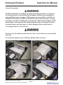
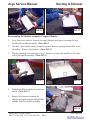
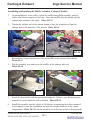
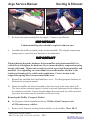
Argo Service Manual Ducting & Exhaust SECTION DE Ducting & Exhaust Table of Contents General Instructions............................................................................. DE-2 Removing the Muffler (Conquest Models Prior to C19672).................................................... DE-3 Disassembling the Muffler Assembly (Conquest Models Prior to C19672).................................................... DE-5 Assembling the Muffler Assembly (Conquest Models Prior to C19672).................................................... DE-6 Removing the Muffler (Conquests from C19672).............................. DE-7 Installing the Muffler (Conquests from C19672)............................... DE-8 Removing the Muffler (Response, Vanguard2 & Vanguard)............ DE-8 Installing the Muffler (Response, Vanguard2 & Vanguard)............. DE-10 Remove the Muffler (Bigfoot Models).................................................DE-11 Installing the Muffler (Bigfoot Models).............................................. DE-11 Spark Arrestor Information & Maintenance..................................... DE-11 Removing the Intake Duct (Response, Bigfoot, Vanguard2 & Vanguard).................................... DE-12 Installing the Intake Duct (Response, Bigfoot, Vanguard2 & Vanguard).................................... DE-13 Removing the Intake Duct (Conquest Models)...................................DE-13 Installing the Intake Duct (Conquest Models)....................................DE-14 Removing the Exhaust Ducting (Response, Bigfoot, Vanguard2 & Vanguard).................................... DE-14 Installing the Exhaust Ducting (Response, Bigfoot, Vanguard2 & Vanguard Models)........................DE-14 Ontario Drive & Gear Limited PH.(519)- 662-2840 FAX (519)- 662-2421 www.odg.com DE-1 Ducting & Exhaust Argo Service Manual General Instructions Detailed information on standard workshop and safety procedures, and general servicing operations is not included in this manual, which has been prepared to assist qualified service personnel. ODG assumes no responsibility or liability for PERSONAL INJURY or VEHICLE DAMAGE which results from any servicing procedure performed, including those instructions outlined in this manual. Before performing a servicing operation, an individual must have determined to his/her satisfaction that a personal injury or vehicle damage will not result from the servicing procedure or tools selected. Do not service the exhaust system when it is hot! Severe burns can occur to hands and arms. Eye protection must be worn at all times during vehicle servicing. Ontario Drive & Gear Limited PH.(519)- 662-2840 FAX (519)- 662-2421 DE-2 www.odg.com Argo Service Manual Ducting & Exhaust Removing the Muffler (Conquest Models) On Conquests manufactured prior to C19672: 1. Remove the 2 fasteners in the top of the heat shield. Photo DE-1 Depending on the age of the vehicle, a few earlier models utilized a fiberglass heat shield. This part is no longer available but is fully exchangeable with the newer version. Collect the 2 spacers that are installed beneath each fastener 2. Remove the 2 fasters securing the manifold cover to the muffler shield assembly and remove the manifold cover. Photo DE-2 & 3 DE-1 DE-2 DE-3 DE-4 3. The lower shroud is secured by 2 more fasteners. Remove the 2 fasteners and lift the lower shroud from the vehicle. Photo DE-4 4. Disconnect the muffler at the manifold. Photo DE-5 The muffler and exhaust manifold are joined together with 2 bolts, 4 flatwashers, 2 compression springs and 2 locking style nuts. Refer to the illustration in the appropriate parts manual for a breakdown and orientation of the hardware. Ontario Drive & Gear Limited PH.(519)- 662-2840 FAX (519)- 662-2421 www.odg.com DE-3 Ducting & Exhaust Argo Service Manual DE-5 5. DE-6 There are 2 fasteners securing the the entire muffler assembly to the lower body. These are located at the lower body under the front wheel. It may prove easier to remove the front wheel to access the fastener heads with a socket or wrench. Photo DE-6 & 7 DE-7 DE-8 6. Pull the muffler and shroud assembly into the engine compartment area enough for the tailpipe to clear the outside exhaust screen. Turn the assembly 90 degrees and shove it back over the wheel well temporarly until the exhaust manifold has been removed. Photo DE-8 7. Unbolt the exhaust manifold and remove it from the engine. Photo DE-9 8. Slide the muffler asssembly towards the engine compartment and up and out of the vehicle. Photo DE-10 Compress the rubber shock mounted lower support to narrow the width of the assembly while pulling up, and out from the compartment. Ontario Drive & Gear Limited PH.(519)- 662-2840 FAX (519)- 662-2421 DE-4 DE-9 www.odg.com Argo Service Manual Ducting & Exhaust DE-10 DE-11 Disassembling the Muffler Assembly (Conquest Models) 1. On a clean work surface, remove the single fastener and spacer securing the heat shield to the muffler assembly. Photo DE-11 2. The above heat shield removed exposes another fastener securing the muffler to the shrouding. Remove this fastener. Photo DE-12 3. Flip the assembly over and remove the 2 fasteners securing the muffler on the other side of the shield assembly. Photo DE-13 DE-12 4. Slide the muffler assembly from the heat shield. Photo DE-14 5. Remove the fastener securing the tailpipe and spark arrestor and pull the tailpipe from the muffler assembly. DE-13 DE-14 Ontario Drive & Gear Limited PH.(519)- 662-2840 FAX (519)- 662-2421 www.odg.com DE-5 Ducting & Exhaust Argo Service Manual Assembling and Installing the Muffler Assembly (Conquest Models) 1. On an uncluttered work surface, orient the muffler heat shield assembly with the rubber shock lower support, to the back. Insert the muffler into the shroud with the exhaust inlet situated to the right. Photo DE-15 2. Turning the tailpipe end of the shroud around to face the assembler will put the tailpipe also to the right side of the shroud. Photo DE-16 DE-15 DE-16 3. Reinstall the 2 lower fasteners to secure the muffler at the bottom of the shroud. Photo DE-17 4. Flip the assembly over and secure the muffler at the exhaust inlet end. Photo DE-18 DE-17 DE-18 5. Secure the heat shield with the appropriate hardware. Refer to your illustrated parts manual for correct hardware and orientation. Photo DE-19 6. Install the assembly into the vehicle at 90 degrees, compressing the rubber mounted lower support to ease the installation and provide enough clearance in the engine compartment. Photo DE-20 Set the assembly on to the front wheel well temporarily Ontario Drive & Gear Limited PH.(519)- 662-2840 FAX (519)- 662-2421 DE-6 www.odg.com Argo Service Manual Ducting & Exhaust DE-19 7. DE-20 Re-fasten the exhaust manifold to the engine. Torque to specification. IMPOR TANT IMPORT Exhaust manifold gaskets should be replaced with new ones 8. Assemble the muffler assembly to the exhaust manifold. The original compression springs may be reused but new hardware is recommended. IMPOR TANT IMPORT When tightening down the hardware between muffler and exhaust manifold, it is critical not to overtighten the hardware. By no means should the compression spring become coil bound. Tighten only enough to provide a good seal between muffler and manifold. Over tightening can cause undue stress at the muffler inlet due to the twisting and turning of the vehicle under application. Correct tension at the compression spring allows for movement in this area. 9. Reinstall the manifold heat shield and lower cover. Use the appropriate hardware as illustrated in your parts manual. 10. Fasten the muffler and shroud assembly to the lower body at the front wheel well. The lower rubber mounted support is slotted to provide adjustment for the tailpipe at the exhaust screen hole. Ensure that the tailpipe does not touch any of the surrounding screen area and secure the assembly to the lower body. Removing the Muffler (Conquest Models) On Conquest vehicles manufactured from C19686, all 6x6 Conquests and all 35th anniversary vehicles: 1. Remove the 4 fasteners securing the heat shield over the muffler. Photo DE-21 Ontario Drive & Gear Limited PH.(519)- 662-2840 FAX (519)- 662-2421 www.odg.com DE-7 Ducting & Exhaust Argo Service Manual 2. Disconnect the 2 extension springs connecting the tailpipe to the muffler and remove the tailpipe. Photo DE-22 3. Unfasten the muffler at the engine and remove. DE-21 DE-22 Installing the Muffler (Conquest Models ) 1. Install the muffler to the engine exhaust manifold and torque to specifications. IMPOR TANT IMPORT New exhaust gaskets are recommended when ever servicing the muffler system. 2. Install the tailpipe/spark arrestor to the muffler, connecting with 2 extension springs. 3. Install the heat shield over the muffler, securing with 4 fasteners. Refer to the illustrated parts manual for correct hardware and orientation. Removing the Muffler (Response, Vanguard2 & Vanguard Models) 1. Remove the exhaust duct cover. On 6x6 Vanguards manufactured prior to S8131: i. Remove the 3 fasteners securing the exhaust duct cover and remove the cover. This exhaust shroud system utilizes a duct below the muffler. See the appropriate illustrated parts manual for component structure on these earlier models. On vehicles manufactured from S8131, SN8138, RB12075 and prior to S13434, N13436, R19647: i. Remove the 3 fasteners that secure the exhaust duct cover and remove the cover. Photo DE-23 On vehicles manufactured from S13434, N13436, and R19647: i Remove the 4 fasteners that secure the exhaust duct cover and remove the cover. Ontario Drive & Gear Limited PH.(519)- 662-2840 FAX (519)- 662-2421 DE-8 www.odg.com Argo Service Manual Ducting & Exhaust 2. Disconnect the extension springs. On models manufactured prior to R19647, S13434 & N13436: i. Remove the extension springs connecting the muffler to the exhaust manifold. Photo DE-24 DE-23 DE-24 On models manufactured from R19647, S13434 & N13436: i. Disconnect the extension springs connecting the tailpipe to muffler and pull the tailpipe out of the vehicle from the engine compartment. Photo DE-25 3. Remove the muffler. On vehicles manufactured from S6999, SN8138, RB12075 and prior to S13434, N13436, R19647: i. Pull the muffler from the exhaust ducting. Photo DE-26 DE-25 i. DE-26 On models manufactured from R19647, S13434 & N13436: Unfasten the muffler from the engine and remove. Ontario Drive & Gear Limited PH.(519)- 662-2840 FAX (519)- 662-2421 www.odg.com DE-9 Ducting & Exhaust Argo Service Manual Installing the Muffler (Response, Vanguard2 and Vanguard Models) 1. Install the muffler On vehicles manufactured from S6999, SN8138, RB12075 and prior to S13434, N13436, R19647: i. Assemble the muffler into the exhaust ducting aligning the tailpipe with the outlet hole in the exhaust screen. The tailpipe should be facing slightly down and towards the rear of the vehicle. Photo DE-27 ii Connect the extension springs between the muffler and exhaust manifold. On 6x6 Vanguard vehicles produced prior to S8131, the outlet pipe of the muffler is straight cut. This tailpipe protrudes straight out of the exhaust screen. Refer to the illustration in the appropriate parts manual for vehicles manufactured in this serial number range. All vehicles manufactured from RB12075, SN7841, S8131 and prior to R19647, S13434 & N13436 are as in Photo DE-27. DE-27 DE-28 On models manufactured from R19647, S13434 & N13436: i. Reassemble the muffler to the engine and torque to specifications. ii Slip the tailpipe, from the engine compartment side, through the exhaust screen hole and connect at the muffler with 2 extension springs. Photo DE-28 2. Reinstall the exhaust duct cover using the appropriate hardware refering to the illustrated parts manual. 6x6 Vangards manufactured prior to S8131, utilize a shroud below the muffler as well. Ontario Drive & Gear Limited PH.(519)- 662-2840 FAX (519)- 662-2421 DE-10 www.odg.com Argo Service Manual Ducting & Exhaust Removing the Muffler (Bigfoot Models) 1. Remove the four fasteners securing the muffler heat shield and remove the shield. 2. Disconnect the extension springs between the tailpipe and muffler and pull the tailpipe from the engine compartment. 3. Remove the muffler at the engine Installing the Muffler (Bigfoot Models) IMPOR TANT IMPORT Always replace exhaust gaskets when servicing the muffler system. 1. Attach the muffler at the engine and torque to specifications 2. Slip the tailpipe, from the engine compartment side, through the exhaust screen hole and connect at the muffler with 2 extension springs. 3. Assemble the heat shield to the top of the muffler using the 4 fasteners required. Spark Arrestors Cleaning the Spark Arrestor (Only for equipped models) Models Equipped with Spark Arrestors. Conquest All Models Response Models manufactured from R19647 Bigfoot Models manufactured from BF13028 Vanguard2 Models manufactured from N13436 Vanguard Models manufactured from S13434 Conquest 6x6 Models manufactured from C12747 After operating the engine, do not touch any part of the exhaust system until it has sufficient time to cool! 1. Keep a record of the number of hours of engine use. The spark arrester should be removed, cleaned and inspected every 50 hours of operation. Ontario Drive & Gear Limited PH.(519)- 662-2840 FAX (519)- 662-2421 www.odg.com DE-11 Ducting & Exhaust Argo Service Manual 2. Remove the tail pipe assembly by disconnecting the springs from the muffler attached to the tail pipe. 3. The screen-type spark arrester assembly is located inside the tail pipe. It is fastened with one (1) slotted washer-head hex screw. Find the screw on the side of the outlet tube. 4. Remove the screw and save it for step 9. 5. Take off the screen-type spark arrester assembly. 6. Shake loose particles out of the screen assembly. 7. Clean the screen with a wire brush. (Soak it in oil solvent if necessary.) 8. If any breaks in the screen or weldments are discovered, replace the assembly. 9. Return the screen assembly to the outlet tube and refasten it with the screw from Step 4. Removing the Intake Duct (Response, Bigfoot, Vanguard2 & Vanguard Models) 1. Locate the 2 fasteners securing the intake duct to the hood frame assembly and remove. There are 2 spacers assembled with the fasteners. Photo DE-29 2. Undo the fuel line from the nylon clips securing it to the intake duct. 3. Pull the ducting from the vehicle. Navigate it towards the front of the vehicle pulling it up, and out. Photo DE-30 DE-29 DE-30 6x6 Vanguards manufactured prior to S8131 will have a spring attached at the rear of the intake and connected to a small molly hook that is riveted to the lower body wheel well. See the appropriate illustrated parts manual. Ontario Drive & Gear Limited PH.(519)- 662-2840 FAX (519)- 662-2421 DE-12 www.odg.com Argo Service Manual Ducting & Exhaust Installing the Intake Duct (Response, Bigfoot, Vanguard2 & Vanguard Models) 1. Install the intake duct inserting it closest to the front of the vehicle. This is where the widest available area allows it to be pushed into the vehicle. Position it in front of the engine flywheel fan assembly. 2. Fasten the intake duct to the hood support assembly using the spacers and 2 fasteners. On 6x6 Vanguards manufactured prior to S8131, reconnect the extension spring from the intake duct to the molly hook on the lower body. 3. Secure the fuel line to the nylon clips at the intake duct. Removing the Intake Duct (Conquest Models) Conquest models maufactured prior to CB17117 utilize a sheet metal style intake duct. Intake ducts on Models manufactured from the above serial number, are made of moulded plastic. Earlier sheet metal ducts are no longer available, but the newer style is fully exchangeable. However, optional parts are necessary when ordering your replacement. To remove the intake duct on Conquest models, the upper body must be split from the lower body. 1. Peel off the rubber bumper assembly from the vehicle. You need only strip it off far enough off to drill out the specified rivets. 2. Using a 3/16" drill bit, remove the rivets starting from the front center of the vehicle to approximately the dash area. Photo DE-31 DE-31 3. Separate the upper and lower body, supporting it apart using a couple of 2x4 pieces of wood. 4. Locate the fasteners securing the intake duct to the lower body and remove. 5. Raise the upper body from the lower high enough to accommodate the height of the duct as you pull it out from between the two. Ontario Drive & Gear Limited PH.(519)- 662-2840 FAX (519)- 662-2421 www.odg.com DE-13 Ducting & Exhaust Argo Service Manual Installing the Intake Duct (Conquest Models) 1. Slip the intake duct between upper and lower body. 2. Position the duct so that both duct and lower body mounting holes are aligned. 3. Install the hardware required to fasten the duct to the lower body 4. Re-rivet the upper body to the lower using washers on the underside of the vehicle. Reinstall the rubber bumper. Removing the Exhaust Ducting (Response, Bigfoot, Vanguard2 & Vanguard Models 1. Perform the servicing procedure, Removing the Muffler (Response, Vanguard2 & Vanguard Models) or: Perform the servicing procedure, Removing the Muffler (Bigfoot Models) 2. Remove the 2 fasteners securing the exhaust ducting to the hood support brace. Photo DE-32 3. The exhaust ducting is secured at the other end by 2 body rivets located at the upper body beneath the rubber bumper. Photo DE-33 Peel back the bumper and drill out both rivets. DE-32 4. DE-33 Pull the duct assembly in towards the engine compartment and up and out of the vehicle. Installing the Exhaust Ducting (Response, Bigfoot, Vanguard2 & Vanguard Models) 1. Insert the ducting into the engine compartment. Slip the exhaust duct support between the upper and lower body aligning the holes in the support, with the rivet holes of the previously removed rivets. 2. Insert 2 body rivets through the body and shroud support, and secure with 2 washers below. Ontario Drive & Gear Limited PH.(519)- 662-2840 FAX (519)- 662-2421 DE-14 www.odg.com Argo Service Manual Ducting & Exhaust 3. Fasten the duct at the upper hood brace assembly 4. Perform the servicing procedure, Installing the Muffler (Response, Vanguard2 and Vanguard Models) or: Installing the Muffler (Bigfoot Models) 5. Reinstall the bumper. Removing the Exhaust Ducting (Conquest from C19686, all 6x6 Conquests and all 35th anniversary vehicles) 1. Perform the servicing procedure, Removing the Muffler (Conquest) on page DE-7 of this service guide. 2. Remove the 2 fasteners securing the exhaust ducting to the hood support brace. See Photo DE-32 previous page. 3. The exhaust ducting is secured at the other end by a body rivet located at the upper body beneath the rubber bumper. See Photo DE-33 previous page Peel back the bumper and drill out both rivets. 4. Pull the duct assembly in towards the engine compartment and up and out of the vehicle. Installing the Exhaust Ducting (Conquest from C19686, all 6x6 Conquests and all 35th anniversary vehicles) 1. Insert the ducting into the engine compartment. Slip the exhaust duct support between the upper and lower body aligning the holes in the support, with the rivet holes of the previously removed rivets. 2. Insert 2 body rivets through the body and shroud support, and secure with 2 washers below. Fasten the duct at the upper hood brace assembly 3. 4. Perform the servicing procedure, Installing the Muffler (Conquest) on page DE-8 of this service guide. 5. Reinstall the bumper. Ontario Drive & Gear Limited PH.(519)- 662-2840 FAX (519)- 662-2421 www.odg.com DE-15