1
Go To Table Of Contents
Next
Canis Major
Veterinary Tables
®
Model Numbers:
CMWO
Service and
Parts Manual
CMWS
CMDT-45
CMDT-WS-45
CMDT-60
CMDT-WS-60
FOR USE BY MIDMARK TRAINED TECHNICIANS ONLY
SF-1902
Style B
Part No. 004-0542-00 Rev. B (11/13/13)
Back
OPERATION &
TROUBLESHOOTING
Section C
Symbols ...................................... iii
Ordering Parts ............................ iii
Serial Number Location ............. iii
Specifications
CMWO & CMWS ......................... iv
CMDT (WS) ................................. v
Model Identification /
Scheduled Maintenance ............ vi
Warranty Information ................. vii
Back Panel ..................................... C-2
Table Top ....................................... C-3
Safety Pan (Dry Table Only) ......... C-4
WIRING DIAGRAMS
EXPLODED VIEWS / PARTS LISTS
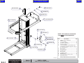
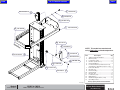
Wet Tables
CMDT-45, CMDT-WS, CMDT-60,
CMDT-WS-60, CMDT-GC-60 ......... A-2
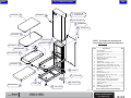
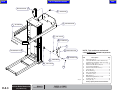
Dry Tables
CMWO, CMWS ............................... A-3
COMPONENT
TESTING & REPLACEMENT
Actuator & Control Box ................ B-2
Foot Control .................................. B-5
Rocker Switch ............................... B-8
Safety Switch ................................. B-10
Hand Control ................................. B-12
Limit Switch ................................... B-14
Receptacle ..................................... B-16
Pump .............................................. B-18
Screen and Water Hose ................ B-20
Water Sensor ................................. B-22
Spray Nozzle and Hose Assy ........ B-25
Scale ............................................... B-26
Scale (Calibration) ......................... B-27
Scale (Transformer) ....................... B-30
Scale (Load Cells) .......................... B-31
Scale (Display Check) ................... B-32
ACCESS PROCEDURES
Section D
GENERAL INFORMATION
Section E
General Information
Section A
Section B
Table Of Contents
Next
CMWO
Dry Table w/o Scale............ D-2*
CMWS
Dry Table with Scale .......... D-3*
CMDT-45 / CMDT-60
Wet Table w/o Scale ........... D-4*
Electrical Box w/o Scale .... D-5*
CMDT-WS-45 / CMDT-WS-60
Wet Table with Scale .......... D-6*
Electrical Box with Scale ... D-7*
CMWO/CMWS .................... E-2*
CMDT-45 / CMDT-WS-45 .... E-3*
CMDT-60 / CMDT-WS-60 .... E-3*
CMDT-GC-60 ....................... E-3*
* Indicates multiple pages due to model / serial number break(s)
© Midmark Corporation 2007
SF-1902 Rev. 2/22/12
Back
General Information
Go To Table Of Contents
Next
General Information
Symbols
DANGER
Indicates an imminently hazardous situation which
will result in serious or fatal injury if not avoided. This
symbol is used only in the most extreme conditions.
WARNING
Indicates a potentially hazardous situation which
could result in serious injury if not avoided.
CAUTION
Indicates a potentially hazardous situation which may
result in minor or moderate injury if not avoided. It may also be
used to alert against unsafe practices.
Equipment Alert
Indicates a potentially hazardous situation
which could result in equipment damage if not avoided.
Ordering Parts
The following information is required when ordering parts:
• Serial number & model number
• Part number for desired part.
[Refer to Exploded Views / Parts Lists section]
Non-warranty parts orders may be faxed to Midmark using
the Fax Order Form in the back of this manual.
For warranty parts orders, call Midmark's Technical Service
Department with the required information.
Hours:
8:00 am until 5:00 pm EST [Monday - Friday]
Phone:
1-(800)-Midmark
Serial Number Location
(Model CMW* shown)
(Model CMDT** similar)
In Section A, test the components in the order indicated.
(ex. 1st then, 2nd )
Refer to Section B for component testing procedures.
The symbols below may be used in this manual to represent
the operational status of table functions and components.
Indicates the function / component is working properly.
No action required.
Indicates the function / component is working,
but a problem exists.
Serial / Model
Number Location
Indicates the function / component is not working at all.
VA1516i
© Midmark Corporation 2007 SF-1902 Rev. 04/09
iii
Back
Go To Table Of Contents
Next
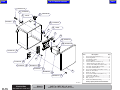
General Information
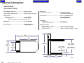
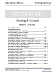
Specifications
(Model CMWO / CMWS)
Patient Weight (maximum) ................................. 300 lbs (136 kgs)
Range of Motion & Dimensions ........................ See illustration on this page
Weight of Table:
w/o packaging & skid ....................................... 315 lbs (142 kg)
w/ packaging & skid ......................................... 372 lbs (169 kg)
(Add 5 lbs (2.2 kg) for units equipped with a scale)
Power Cord: ........................................................ 7 ft. (213 cm) long
Electrical Rating: ................................................ Dedicated Circuit
115 VAC, 60 Hz, 10A
Duty Cycle:
Actuator motor run time: ................................... Intermittent Operation
(1 minute ON / 9 minutes off)
Classifications: ................................................... Class 1, Type B Applied Part,
Ordinary Equipment,
Intermittent Operation
Table Speed:
150 lb patient ................................................. < 40 seconds
<150 lb or >150 lb. patient ............................ 29 to 45 seconds
Usage Enviornment:
Ambient Temperature Range: ....................... 10°C to +40°C (+23°F to 104°F)
Relative Humidity .......................................... 30% to 75% (non-condensing)
Atmospheric Pressure ................................... 700hPa to 1060hPa (0.69atm to 1.05atm)
55.5"
(141 cm)
46.5"
(118.1 cm)
25.5"
(64.8 cm)
60"
(152.4 cm)
21.1"
(53.6 cm)
5.5" (14 cm)
(Max. w/ Pad)
or
5" (12.7 cm)
(Max. w/o Pad)
9"
(22.9 cm)
iv
© Midmark Corporation 2007 SF-1902 Rev. 8/11
44" (111.8 cm)
(Max. w/ Pad)
or
43.5" (110.5 cm)
(Max. w/o Pad)
35"
(88.9 cm)
VA102100i
Back
Go To Table Of Contents
Next
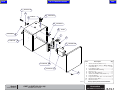
General Information
Specifications
(Models: CMDT-45 / CMDT-WS-45 / CMDT-60 / CMDT-WS-60 )
Patient Weight (maximum) ................................. 300 lbs (136 kgs)
Range of Motion & Dimensions ........................ See illustration on this page
Weight of Table
(CMDT-45 / CMDT-WS-45):
w/o packaging & skid ....................................... 366 lbs (166 kg)
w/ packaging & skid ......................................... 435 lbs (197 kg)
Duty Cycle:
Actuator motor run time: ................................... Intermittent Operation
(1 minute ON / 9 minutes off)
Pump motor run time: ...................................... Intermittent Operation
(thermal protection)
Classifications: ................................................... Class 1, Type B Applied Part,
Ordinary Equipment,
Intermittent Operation
Weight of Table
(CMDT-60 / CMDT-WS-60):
w/o packaging & skid ....................................... 395 lbs (179 kg)
w/ packaging & skid ......................................... 465 lbs (211 kg)
Table Speed:
150 lb patient ................................................. < 40 seconds
<150 lb or >150 lb. patient ............................ 29 to 45 seconds
Usage Enviornment:
Ambient Temperature Range: .......................10°C to +40°C (+23°F to 104°F)
Relative Humidity .......................................... 30% to 75% (non-condensing)
Atmospheric Pressure ...................................700hPa to 1060hPa (0.69atm to 1.05atm)
Power Cord: ........................................................ 4 ft. (121 cm) long
Electrical Rating: ................................................ Dedicated Circuit
115 VAC, 60 Hz, 10A
GFI Receptacle Rating: ...................................... Class A, 2P, 125 VAC, 60HZ
61"
(154.9 cm)
46.5"
(118.1 cm)
60"
(152.4 cm)
25.3"
(64.3 cm)
43.5" (Max.)
(118.1 cm)
62.5"
(158.8 cm)
9.5"" (Min.)
(24.1 cm)
77"
(195.6 cm)
Water Inlet Height
Drain Outlet Height
13"
(33 cm)
11"
(27.9 cm)
VA101000i
© Midmark Corporation 2007 SF-1902 Rev. 8/11
v
Back
Go To Table Of Contents
Next
General Information
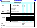
Cleaning
Weekly
Clean stainless steel surfaces with a mild cleaning
agent and rinse and towel dry.
Mechanical Operation
CMDT-WS-60
X
X
X
X
X
X
X
X
X
X
X
X
X
X
X
X
X
X
X
X
Visually inspect components for damage that could
cause problems during procedures or unsafe operation.
X
X
X
X
X
X
Check all mechanical functions using foot control or
hand switches.
X
X
X
X
X
X
X
X
X
X
Wipe painted metal & plastic surfaces with a clean
soft cloth and a mild cleaner.
Clean stainless steel surfaces with a mild cleaning
agent and rinse and towel dry.
Check all mechanical functions using hand control.
Check tabletop safety stop operation.
X
X
Check water system for leaks.
Semi-Annually
X
X
(NOTE: Periodic application of common furniture wax will
ease cleaning and maintain the luster of the surfaces.)
Obvious Damage
CMDT-60
Inspect and clean debris trap bbeneath tabletop.
CMDT-WS-45
Dailly
Cleaning
Service, Adjust, Repair
and/or Replace as Required
(Refer to Service & Parts Manual)
CMDT-45
Inspection
or
Service
CMWS
Interval
CMWO
Scheduled Maintenance
Canis Major Veterinary Tables
Replace any missing or illegible labels.
X
X
X
X
X
X
Lubricate
Lubricate lift mechanism columns (earlier units only).
X
X
X
X
X
X
Hardware
All fasteners must be present and fastened securely.
X
X
X
X
X
X
Inspect power cord and all visible wiring for damage.
X
X
X
X
X
X
Be sure all electrical connections are tight.
X
X
X
X
X
X
Labels / Decals
Electical System
Date of Service:
_____ / _____ / _______
Code:
_____________________________________
Model: ______________________________________________
Location: ______________________________________________________________________________
________________________________________________________________________________________
________________________________________________________________________________________
Serial Number: _______________________________________
Service Technician:
(print name)
(signiture)
vi
___________________________________________________________________
___________________________________________________________________
© Midmark Corporation 2007 SF-1902
Comment: ___________________________________________
_____________________________________________________
_____________________________________________________
_____________________________________________________
_____________________________________________________
Back
Go To Table Of Contents
Next
General Information
Warranty Information
SCOPE OF WARRANTY
Midmark Corporation (“Midmark”) warrants to the original purchaser its new Animal Care
products and components (except for components not warranted under “Exclusions”)
manufactured by Midmark to be free from defects in material and workmanship under
normal use and service. Midmark’s obligation under this warranty is limited to the repair
or replacement, at Midmark’s option, of the parts or the products the defects of which
are reported to Midmark within the applicable warranty period and which, upon
examination by Midmark, prove to be defective.
Additional Information
Failure to follow the guidelines listed below will void the
warranty and/or render the table unsafe for use.
•
If a malfunction is detected, do not use the table until
necessary repairs are made.
•
Do not attempt to disassemble table, replace
components, or perform adjustments unless you are
a Midmark authorized service technician.
•
Do not use another manufacturer's parts to replace
malfunctioning components. Use only Midmark
replacement parts
APPLICABLE WARRANTY PERIOD
The applicable warranty period, measured from the date of delivery to the original user,
shall be one (1) year for all warranted products and components except tabletop mat
which shall be ninety (90) days.
EXCLUSIONS
This warranty does not cover and Midmark shall not be liable for the following: (1) repairs
and replacements because of misuse, abuse, negligence, alteration, accident, freight
damage, or tampering; (2) products which are not installed, used, and properly cleaned
as required in the Midmark “Installation” and or “User’s” Manual for this applicable product;
(3) products considered to be of a consumable nature; (4) accessories or parts not
manufactured by Midmark; (5) charges by anyone for adjustments, repairs, replacement
parts, installation, or other work performed upon or in connection with such products
which is not expressly authorized in writing in advance by Midmark.
EXCLUSIVE REMEDY
Midmark’s only obligation under this warranty is the repair or replacement of defective
parts. Midmark shall not be liable for any direct, special, indirect, incidental, exemplary,
or consequential damages or delay, including, but not limited to, damages for loss of
profits or loss of use.
NO AUTHORIZATION
No person or firm is authorized to create for Midmark any other obligation or liability in
connection with the products.
THIS WARRANTY IS MIDMARK’S ONLY WARRANTY AND IS IN LIEU OF ALL OTHER
WARRANTIES, EXPRESS OR IMPLIED. MIDMARK MAKES NO IMPLIED
WARRANTIES OF ANY KIND INCLUDING ANY WARRANTIES OF MERCHANTABILITY
OR FITNESS FOR ANY PARTICULAR PURPOSE. THIS WARRANTY IS LIMITED TO
THE REPAIR OR REPLACEMENT OF DEFECTIVE PARTS.
© Midmark Corporation 2007 SF-1902
vii
Back
Go To Table Of Contents
Section A
Troubleshooting
Next
Function / System
Wet Tables
Go To Page:
Page
CMDT-45, CMDT-WS, CMDT-60,
CMDT-WS-60, CMDT-GC-60 ................. A-2
Dry Tables
CMWO, CMWS ..................................... A-3
© Midmark Corporation 2007 SF-1902
A-1
Back
Go To Table Of Contents
Next
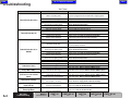
Troubleshooting
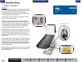
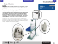
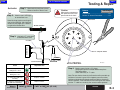
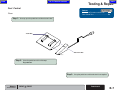
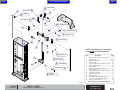
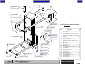
Theory of Operation
Refer To:
Troubleshooting
Wet tables
With the table's power cord properly connected, facility supply
voltage (115 VAC) is supplied thru the cord to the GFI (Ground
Fault Interruption) receptacle and into the electrical box.
Current flows to the water sensor, pump, timer, power supply
for scale (if applicable) and control box.
Go ToPage
Page:
Wet Table ............................................. A-4
Scale .................................................... A-6
Receptacle
The control box reduces the voltage and supplies 24 VDC to
the limit switch and hand control.
The current in the hand control continuously flows back to the
control box thru separate wires for table function. When a
direction is selected from the hand control, this "signal voltage"
is removed from the wire corresponding to the selected function. When the signal voltage is removed, the control box
activates the actuator lifting the table up or down.
(Older version shown)
Hand Control
Water
Sensor
When the sprayer hand control is activated for water, it flows
in through a hot and cold water intake connection. Hot and cold
water flow together though a mixing valve which is factory set
at 70° F (21°C) but can be adjusted up to 120° F (49°C).
Mixed water then flows through to a shut-off valve and then on
to the sprayer.
Water is collected in a stainless steel pan and drains through a
screen and out the drain hose. Water flows down thru the drain
hose and activates the water sensor which starts the pump.
The water then travels through the pump and out into the drain.
Whenever the water sensor senses water running past it the
pump will be activated.
Screen
When the sensor no longer senses water, the timer is activated
which keeps the pump running for 3 seconds and empties the
table plumbing of water.
VA108500
A-2
Wet Table Operation
© Midmark Corporation 2007 SF-1902 Rev. 8/11
Models:
Serial Numbers:
CMDT-45
CMDT-WS-45
CMDT-60
CMDT-WS-60
CMDT-GC-60
ALL
ALL
ALL
ALL
ALL
Back
Go To Table Of Contents
Next
Troubleshooting
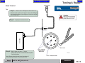
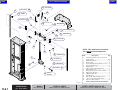
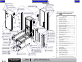
Theory of Operation
Go To Page
Page:
Refer To:
Troubleshooting
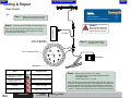
Dry Tables
With the table's power cord properly connected, facility supply voltage (115 VAC)
is supplied thru the cord to the receptacle for scale power supply (if applicable)
and control box.
Dry Table .............................................. A-5
Scale .................................................... A-6
The control box reduces the voltage and supplies 24 VDC to the lift actuator and
energizes the safety and rocker (up/down) switches.
Rocker
Switch
The current in the rocker switches and foot control continuously flows back to the
control box through separate wires for table raise and lower function. When a
direction is selected and the rocker switch is activated, the "signal voltage" is
interrupted from the wire corresponding to the selected function. When the signal
voltage is interrupted, the control box activates the actuator moving the table
either up or down.
The table has a safety pan directly beneath the table top. If an obstruction is
encountered as the table top is descending the safety switches will activate and
the table will stop. In this instance the table will always rise when the up switch is
activated. (unless the table is in the full up position.)
Control
Box
Actuator
VA104700
Models:
Serial Numbers:
CMWO
CMWS
ALL
ALL
Dry Table Operation
© Midmark Corporation 2007 SF-1902
A-3
Back
Go To Table Of Contents
Next
Troubleshooting
Wet Table
Problem
Probable Cause
Correction
Table is not getting power.
Table Will Not Go Down
Verify unit is plugged into and wall outlet that is supplying power.
Wires or cord damaged.
Obstruction
Hand Control not getting power.
Control cord is damaged.
Limit switch not set properly.
Table is at maximum height.
Visually check wires and cords for power supply.
Check for Obstacles under the table.
Verify hand control plug is fully inserted and making proper connection.
Refer to: Section B Hand Control
Replace control cord. Refer to: Section B Control Box
Adjust limit switch. Refer to: Section B Limit Switch
Try moving table down and then back up.
Table is not getting power.
Verify unit is plugged into a wall outlet that is supplying power.
Control cord is damaged.
Replace control cord. Refer to: Section B Control Box
Wires or cord is damaged.
Visually check power supply and cords for damage.
Table is not getting power.
Verify unit is plugged into a wall outlet that is supplying power.
Table Will Not Go UP
Press the reset button on the GFI receptacle.
Try to move table up and down.
Receptacle needs reset.
Table Will Not Go UP or
DOWN
Hand control not getting power.
Replace control cord. Refer to: Section B Control Box
Control cord is damaged.
Wires or cord is damaged.
Visually check power supply and cords for damage.
Hand control not getting power.
Limit switch not set properly.
Actuator not working.
Verify hand control plug is fully inserted and making proper connection.
Refer to: Section B Hand Control
Adjust limit switch. Refer to: Section B Limit Switch
Check actuator. Refer to: Section B Actuator
Clean screen. Refer to: Section B Screen
Clean screen and drain hose. Refer to: Section B Screen
Check water sensor. Refer to: Section B Water Sensor
Table Won't Drain
Screen is clogged.
Drain is clogged.
Water sensor may need replaced.
Pump Won't Start
Water sensor set to high.
Adjust water sensor and timer. Refer to: Section B Water Sensor
Pump Won't Shut Off and
Continues to run without
Water
Water sensor set to low.
Adjust water sensor and timer. Refer to: Section B Water Sensor
Water sensor may need replaced.
Check water sensor. Refer to: Section B Water Sensor
Has old style 1 1/2" fitting.
Replace with new 3" fitting.
Refer to: Section B Spray Nozzle and Hose Assembly
Water Sensor Light is On but
Pump not On
Pump may need replaced.
Check Pump. Refer to: Section B Pump
Pump Running But Not
Pumping Water
Pump may need replaced.
Check Pump. Refer to: Section B Pump
Spray Hose Leaking
A-4
Verify hand control plug is fully inserted and making proper connection.
Refer to: Section B Hand Control
Wet Table
Troubleshooting
© Midmark Corporation 2007 SF-1902
Models:
Serial Numbers:
CMDT-45
CMDT-WS-45
ALL
CMDT-60
ALL
ALL
CMDT-WS-60
CMDT-GC-60
ALL
ALL
Back
Go To Table Of Contents
Next
Troubleshooting
Dry Table
Problem
Probable Cause
Table is not getting power.
Verify unit is plugged into and wall outlet that is supplying power.
Control cord is damaged.
Wires or cord damaged.
Replace control cord. Refer to: Section B Control Box
Visually check power supply and cord for damage.
Table Will Not Go DOWN
On Dry Tables: Safety switch is activated.
Foot control not getting power.
Loose connection rocker switch.
Table is at maximum height.
Table is not getting power.
Control cord is damaged.
Table Will Not Go UP
Wires or cord damaged.
Foot control not getting power.
Loose connection in rocker switch.
Table is not getting power.
Wires or cord damaged.
Control cord is damaged.
Table Will Not Go UP or DOWN
Foot control not getting power.
Loose connection in rocker switch.
Actuator not working.
Models:
Serial Numbers:
CMWO
CMWS
ALL
ALL
Correction
Verify area around table is clear of obstacles. There are four switches, two on
each side, which act as contact points for the safety pan. When the pan is
pushed up it hits one or more of these switches which in turn breaks the
electrical connection and stops the table. Usually jiggling the pan will free-up
the offending switch. Refer to: Section B Safety Switch
Verify foot control plug is fully inserted and making proper connection.
Refer to: Section B Foot Control
Check rocker switch connections. Refer to: Section B Rocker Switch
Try moving table down and then back up.
Verify unit is plugged into and wall outlet that is supplying power.
Replace control cord. Refer to: Section B Control Box
Visually check power supply a cord for damage.
Verify foot control plug is fully inserted and making proper connection.
Refer to: Section B Foot Control
Check rocker switch connections. Refer to: Section B Rocker Switch
Verify unit is plugged into and wall outlet that is supplying power.
Visually check power supply a cord for damage.
Replace control cord. Refer to: Section B Control Box
Verify foot control plug is fully inserted and making proper connection.
Refer to: Section B Foot Control
Check rocker switch connections. Refer to: Section B Rocker Switch
Check actuator. Refer to: Section B Actuator
Dry Table
Troubleshooting
© Midmark Corporation 2007 SF-1902
A-5
Back
Go To Table Of Contents
Next
Troubleshooting
Scale
Problem
No Display
Probable Cause
Table is not getting power or has a loose connection.
Transformer may need replaced.
Incorrect weights
Display Segment's Missing, Illegible
(Faint) or Flickering
On
and Off
Obstruction.
Scale needs reset.
Scale needs calibrated.
Transformer may need replaced.
Platform not level.
Display "Locked" and not Changing
Excessive load.
Remove excess load.
Scale needs rebooted.
Unplug the scale power supply for a minute to reset, and try to zero
again.
Scale needs calibrated.
Calibrate scale. Refer to: Section B Scale Calibration
Scale needs rebooted.
Unplug the scale power supply for a minute to reset, and try to zero
again.
Scale needs calibrated.
Calibrate scale. Refer to: Section B Scale Calibration
Weight on the scale platform exceeds 300 lbs.
Remove excess load.
Load placed on scales too heavy on a corner.
Center load on the scale platform.
Examination table top out of place.
ZERO & Unit keys Do Not Work
Scale needs reset.
6FDOH'RHVQ¶W:RUN3URSHUO\$IWHU
Replacing Scale Board and or Load
Cells
Scale needs calibrated.
A-6
© Midmark Corporation 2007 SF-1902 Rev 2/22/12
Disconnect display and plug into the other receptacle. Unplug the
Calibrate scale. Refer to: Section B Scale Calibration
Check transformer. Refer to: Section B Scale (Transformer)
Verify the platform is level and supported evenly at corners.
Remove source of motion.
Load cell needs replaced or load cell cable damaged.
Scale
Troubleshooting
Check transformer.
Verify there is nothing interfering with the scale platform underneath
and on all sides. Check display for correct units, lbs or kg.
Motion on scale.
The scale is underloaded.
Displays "LoLdX"
Verify unit is plugged into a wall outlet that is supplying power.
Wire harness from the scale display to the main PC board Verify wire harness is fully connected to display. Refer to: Section
is not fully docked.
B Scale (Display)
ZERO Key Does NOT
Reset Zero
Displays "HiLoAd"
Displays"HiLdX"
Correction
Models:
Serial Numbers:
Reposition cover (if applicable) or table top.
Uninstall and reinstall table. Refer to: Section C Table Top
Check load cell. Refer to: Section B Scale (Load Cells)
Disconnect display and plug into the other receptacle. Unplug the
scale power supply for a minute to reset, and try again.
Calibrate scale. Refer to: Section B Scale Calibration
ALL ( If Applicable - Scale is an Accessory)
Back
Go To Table Of Contents
Section B
Testing & Repair
Next
Go To Page:
Components
Page
Actuator & Control Box ......................... B-2
Foot Control .......................................... B-5
Rocker Switch ....................................... B-8
Safety Switch ....................................... B-10
Hand Control ......................................... B-12
Limit Switch .......................................... B-14
Receptacle ............................................ B-16
Pump .................................................... B-18
Screen and Water Hose ........................ B-20
Water Sensor ........................................ B-22
Spray Nozzle and Hose Assembly ...... B-25
Scale .................................................... B-26
Scale (Calibration) ............................... B-27
Scale (Transformer) ............................. B-30
Scale (Load Cells) ................................ B-31
Scale (Display Check) ......................... B-32
© Midmark Corporation 2007 SF-1902
B-1
Back
Go To Table Of Contents
Next
Testing & Repair
*Replacement instructions are
provided with the part.
They are also available on documark.com,
or by clicking on the link in the blue box.
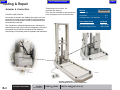
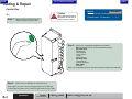
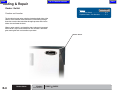
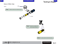
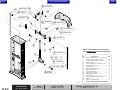
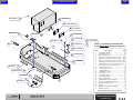
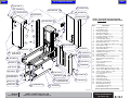
Actuator & Control Box
Function and Location
The actuator is located in the middle of the column and is the
lift mechanism for the work surface. When the hand control or
foot control is activated there is 24 VDC current flow from the
control box to the actuator.
Go To Page:
Refer to:
Page
Actuator Test ........................................ B-3
Control Box ........................................... B-4
Exploded Views / Part Numbers ............ E-1
www.midmark.com:
File Name
Actuator Replacement............... 003-1796-00
The control box is mounted inside the column and serves to
control outputs to the various electrical components. The control
box reduces the 125 VAC line voltage to 24 VDC. When the
indicator light is illuminated, power is supplied to the control box.
Control Box Replacement .......... 003-1797-00
VA106400
VA105500
Only Dry Table Shown
Same Component and Location in Wet Table
B-2
Actuator & Control Box
© Midmark Corporation 2007 SF-1902 Rev. 9/12
Models:
Serial Numbers:
CMWO & CMWS
All
CMDT & CMDT-WS (45 & 60)
All
Back
Go To Table Of Contents
Next
Testing & Repair
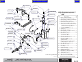
Actuator
Step 1: Remove back panel from column.
Refer to: Section C Back Panel
Caution
When testing components
with power on use care to
prevent electrical shock.
Test
Step 2: Check to see if LED light
Go To Page:
Refer to:
Page
Control Box ........................................... B-4
Section C: Access Procedures ............. C-1
on control box is on.
Metal Band
Note: You have to place your finger in
front of the LED light. See if the light
shines on your finger nail. If there is
no light check Control Box.
Rocker Switches
7
Step 3: Unplug the "T" cable from
1
2
8
the rocker switch cord.
3
6
"T" Cable
4
Control Box
5
Test 2 - Jump #4 and #8
Actuator
To Foot Control
Action
Status
Test 1- Jump #8 and
Ground on Metal Band
Required Action
Table Moves Up and Down
During Test 1 and 2
Check both Rocker Switches
Table Does NOT Move
During Test 1 or 2
Check "T" Cable for Continuity
"T" Cable Does NOT have
Continuity
Replace "T"Cable
"T" Cable Has Continuity and
Table Still Does NOT Move
Replace Actuator
Models:
Serial Numbers:
CMWO & CMWS
All
VA106500
Step 4: Bend a paper clip into a "U" shape.
Hold paper clip with insulated needle nose pliers.
Test holes shown.
Check Continuity in "T" cable.
Note: The two checks shown in the illustration will move table up
and down if actuator is good. If this happens one of the rocker
switches might be bad and needs replaced. Refer to: Section B
Rocker Switches. If the table doesn't move during the two checks,
and the "T" cable has continuity, the actuator needs replaced.
CMDT & CMDT-WS (45 & 60)
All
Actuator
© Midmark Corporation 2007 SF-1902
B-3
Back
Go To Table Of Contents
Next
Testing & Repair
Control Box
Go To Page
Page:
Refer to:
Section C: Access Procedures ............. C-1
Caution
Test
When testing components
with power on use care to
prevent electrical shock.
Step 1: Remove back panel from column.
Exploded Views / Part Numbers ............ E-1
Refer to: Section C Back Panel
Step 3: Check each component plugged into control box.
Refer to Section B (B-1) for test procedure locations.
Wet Table Only
• Receptacle
• Hand Control
• Limit Switch
• Pump
• Water Sensor
Dry Table Only
• Foot Control
• Rocker Switches
Both Tables
• Actuator
Note: If all components test bad, then the control box needs to be replaced.
VA110200
Step 2: Check to see if LED light on control box is on.
Note: Light is very dim. Place your finger under front of LED light.
If control box has power you will see LED light reflect off your finger.
B-4
Control Box
© Midmark Corporation 2007 SF-1902
Models:
Serial Numbers:
CMWO & CMWS
All
CMDT & CMDT-WS (45 & 60)
All
Back
Go To Table Of Contents
Next
Testing & Repair
Foot Control
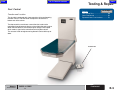
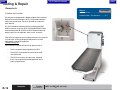
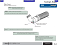
Function and Location
The dry table is equipped with a foot control for raising and lowering
the work surface. The connection receptacle is located at the
bottom rear of the column.
Go To Page:
Refer to:
Page
Foot Control Test .................................. B-6
Clean Foot Control ................................ B-7
Exploded Views / Part Numbers ............ E-1
The foot control has continuous current flow that travels to the
control box through separate wires to raise or lower the work surface.
When the foot control is activated the signal voltage is interrupted
which sends a signal to the control box activating the actuator.
The actuator is then energizes moving the work surface either up or
down.
Foot Control
Models:
Serial Numbers:
CMWO & CMWS
All
Foot Control
© Midmark Corporation 2007 SF-1902 Rev. 4/09
B-5
Back
Go To Table Of Contents
Testing & Repair
Next
Rocker Switches
Foot Control
Go To Page
Page:
Refer to:
Control Box ........................................... B-4
Test
Step 1: Remove back panel from column.
Rocker Switches ................................... B-8
Section C: Access Procedures ............. C-1
Refer to: Section C Back Panel
Caution
Step 2: Check to see if LED light on control box is on.
When testing components
with power on use care to
prevent electrical shock.
Control Box
Note: You have to place your finger in front of the LED
light. See if the light shines on your finger nail. If there
is no light check Control Box.
"T" Cable
Test 1- Jump #8 and
Ground on Metal Band
Step 3: Unplug the foot control
plug from the "T" cable.
Test 2 - Jump #4 and #8
5
4
3
6
8
2
7
Foot Control
VA106900
1
Metal Band
Action
Status
Required Action
Table Moves Up and Down
During Test 1 and 2
Check both Rocker Switches
Table Does NOT Move
During Test 1 or 2
Check "T" Cable for Continuity
"T" Cable Does NOT have
Continuity
Replace "T"Cable
"T" Cable Has Continuity and
Table Still Does NOT Move
Replace Foot Control
B-6
Foot Control
© Midmark Corporation 2007 SF-1902
Models:
Serial Numbers:
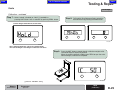
Step 4: Bend a paper clip into a "U" shape.
Hold paper clip with insulated needle nose pliers.
Test holes shown.
Check Continuity in "T" cable.
Note: The two checks shown in the illustration will move table up
and down if Foot Control is good. If this happens one of the rocker
switches might be bad and needs replaced. Refer to: Section B
Rocker Switches. If the table doesn't move during the two checks,
and the "T" cable has continuity, the Foot Control needs replaced.
CMWO & CMWS
All
Back
Go To Table Of Contents
Next
Testing & Repair
Foot Control
Go To Page:
Refer to:
Page
Foot Control Function and Location ....... B-5
Foot Control Test .................................. B-6
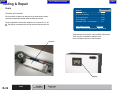
Clean
Step 1: Unsnap apart the pedal box and the electronic box.
Pedal Box
Electronic Box
VA108000
Step 2: Clean the pedal box with a mild soap.
Dry pedal box.
Step 3: Snap the pedal box and the electronic box together.
Models:
Serial Numbers:
CMWO & CMWS
All
Foot Control
© Midmark Corporation 2007 SF-1902
B-7
Back
Go To Table Of Contents
Next
Testing & Repair
Rocker Switch
Go To Page:
Refer to:
Page
Test Rocker Switch ............................... B-9
Function and Location
Exploded Views / Part Numbers ............ E-1
The dry table has two rocker switches located on both sides of the
column. These switches have continuous current flowing through
them that travels to the control box through separate wires for the
tables raise and lower functions.
When a rocker switch is activated the signal voltage is interrupted
which sends a signal to the control box. The actuator is then energizes moving the work surface either up or down.
Rocker Switch
B-8
Rocker Switch
© Midmark Corporation 2007 SF-1902
Models:
Serial Numbers:
CMWO & CMWS
All
Back
Go To Table Of Contents
Next
Testing & Repair
Rocker Switch
Go To Page:
Refer to:
Page
Section C: Access Procedures ............. C-1
Test
Exploded Views / Part Numbers ............ E-1
Step 1: Remove back panel from column.
Warning
Refer to: Section C Back Panel
When testing components
with power on use care to
prevent electrical shock.
Step 2: Disconnect rocker switch wires.
Test Table UP
Test Each Rocker Switch...
Step 3: Bend a paper clip into a "U" shape.
Hold paper clip with insulated needle nose pliers.
Test Red and Green wires to move table up.
Test Orange and Red wires to move table down.
Note: If table moves up and down replace disconnected
rocker switch.
If table does not move up or down reconnect rocker switch
and repeat test on opposite rocker switch.
Models:
Serial Numbers:
CMWO & CMWS
All
Test Table DOWN
Step 4: Connect rocker switches.
Replace back panel.
VA107800
Rocker Switch
© Midmark Corporation 2007 SF-1902
B-9
Rev. 11/14/12
Back
Go To Table Of Contents
Next
Testing & Repair
Safety Switch
Go To Page:
Refer to:
Page
Test Safety Switch ............................... B-11
Function and Location
Exploded Views / Part Numbers ............ E-1
The Dry Table has a safety feature that is designed to disable the
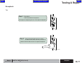
down function when an obstruction is encountered beneath the work
surface.
The feature consist of four micro switches, two on either side, which
are activated by the safety pan.
(Older version shown)
B-10
Models:
Safety Switch
© Midmark Corporation 2007 SF-1902
Serial Numbers:
Rev. 4/09
CMWO & CMWS
All
Back
Go To Table Of Contents
Next
Testing & Repair
Safety Switch
Go To Page:
Refer to:
Page
Section C: Access Procedures ............. C-1
Test
Step 1: Verify there are no obstructions under table.
Jiggling the safety pan will almost always
free up an offending safety switch.
Note: Check to see if table will move down. If not
continue with Step 2.
Mat
Top Cover
Step 2: Remove table top cover and safety pan.
Refer to: Section C Table Top Cover & Safety Pan
Safety Pan
Safety
Switch
By-Pass Safety Switch...
Step 3: • Disconnect wires from switch.
• Bend a paper clip into a "U" shape. Hold paper
clip with insulated needle nose pliers.
• Insert paper clip ends into wire terminals.
Note: Table should move down when switch is jumped.
Bypass each safety switch to find nonworking switch.
Models:
Serial Numbers:
CMWO & CMWS
All
VA107900
Safety Switch
© Midmark Corporation 2007 SF-1902
B-11
Rev. 4/09
Back
Go To Table Of Contents
Next
Testing & Repair
Hand Control
Go To Page
Page:
Refer to:
Hand Control Test ................................. B-11
Exploded Views / Part Numbers ............ E-1
Function and Location
The only control available for the wet table is the hand control which
is used to raise and lower the work surface.
The location to connect the hand control to the table is on the top
left side of the column.
The hand control has continuous current flow that travels to the
control box through separate wires.
When a direction is selected, the signal voltage is interrupted. This
sends a signal to the control box activating the actuator, lifting the
work surface up or down.
VA106300
B-12
Hand Control
© Midmark Corporation 2007 SF-1902
Models:
Serial Numbers:
CMDT & CMDT-WS (45 & 60)
All
Back
Go To Table Of Contents
Next
Testing & Repair
Hand Control
Hand Control
Go To Page
Page:
Refer to:
Control Box ........................................... B-4
Test
Step 1: Check to see if LED light on control box is on.
Note: You have to place your finger in front of the LED light.
See if the light shines on your finger nail. If there is no light
check Control Box.
Caution
When testing components
with power on use care to
prevent electrical shock.
Step 2: Unplug the hand control cord.
6
7
Control Box
5
8
4
1
2
3
Metal Band
Step 3: Bend a paper clip into a "U" shape.
Test 1- Jump #8
and Ground on
Metal Band
VA106800
Hold paper clip with insulated needle nose pliers.
Test holes shown.
Note: The two checks shown in the illustration will
move table up and down if hand control is OK.
Models:
Serial Numbers:
CMDT & CMDT-WS (45 & 60)
All
Test 2 - Jump #4 and #8
Hand Control
© Midmark Corporation 2007 SF-1902
B-13
Back
Go To Table Of Contents
Next
Testing & Repair
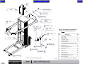
Limit Switch
Go To Page
Page:
Refer to:
Limit Switch Adjustment ....................... B-15
Exploded Views / Part Numbers ............ E-1
Function and Location
The limit switch is located on the inside of the column and prevents
the work surface from lowering beyond a certain point. The control
box reduces the voltage supplied to the switch to 24 VDC.
(Older version shown)
Models:
Limit Switch
Serial Numbers:
B-14
© Midmark Corporation 2007 SF-1902
Rev. 4/09
CMDT & CMDT-WS (45 & 60)
All
Back
Go To Table Of Contents
Next
Testing & Repair
Limit Switch
Refer to:
Page
Go To Page:
Section C: Access Procedures ............. C-1
Exploded Views / Part Numbers ............ E-1
Adjustment
Step 1: Raise Table to maximum height.
Step 2: Remove back panel from column.
Refer to: Section C Back Panel
Step 3: Remove bottom nut on limit switch bracket.
Step 4: Swing bracket forward to adjust limit switch.
Tighten nut.
VA107600
Step 5: Lower table to verify limit switch adjusted height.
Adjust again if necessary.
Install back panel.
Models:
Serial Numbers:
CMDT & CMDT-WS (45 & 60)
All
Limit Switch
© Midmark Corporation 2007 SF-1902
B-15
Back
Go To Table Of Contents
Next
Testing & Repair
Receptacle
Go ToPage
Page:
Refer to:
Receptacle Test .................................... B-17
Exploded Views / Part Numbers ............ E-1
Function and Location
The wet table is equipped with a Duplex receptacle with 125VAC,
Ground Fault Circuit Interrupter (GFCI). This provides additional
safety from ground faults. These can be used for variety electronic devices.
The GFCI should be checked monthly by pressing the TEST
button to see that it trips the GFIC. Pressing the RESET button
should restore power to the GFCI. A GFCI receptacle does not
protect against circuit overloads, short circuits, or shocks.
If the GFCI has tripped and can no longer be reset, it has reached
it's "end of life" and will no longer provide power. It must be
replaced with a new GFCI receptacle.
Troubleshooting Tips
VA106900
GFCI’s contain a lockout feature that will prevent reset if:
•
There is no power being supplied to the GFCI.
•
The GFCI is miswired due to reversal of the LINE
and LOAD leads.
•
The GFCI cannot pass its internal test, indicating
that it may not be able to provide protection in the
event of a ground fault.
B-16
Receptacle
© Midmark Corporation 2007 SF-1902
Models:
Serial Numbers:
CMDT & CMDT-WS (45 & 60)
All
Back
Go To Table Of Contents
Next
Testing & Repair
Receptacle
Test
Step 1: Plug table in.
Press reset button on receptacle.
Verify light on receptacle goes out, if not replace receptacle.
Te
st
Re
s
et
Step 2: Plug an electrical device such as a lamp
or radio to each outlet and verify it will turn on.
If electrical device does not turn on, replace receptacle.
Te
st
Re
s
et
VA106700
Models:
Serial Numbers:
CMDT & CMDT-WS (45 & 60)
All
Receptacle
© Midmark Corporation 2007 SF-1902
B-17
Back
Go To Table Of Contents
Next
Testing & Repair
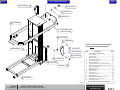
Pump
Go ToPage
Page:
Refer to:
Test Pump ............................................ B-19
Exploded Views / Part Numbers ............ E-1
Function and Location
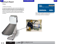
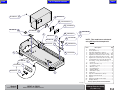
The wet table is equipped with a pump, located at the bottom rear of
the column. The pump is activated by a water sensor located prior to
the inlet of the pump. When the water sensor stops detecting water
movement, the system timer allows the pump to run three additional
seconds. This will ensure the table has been drained completely.
The pump is powerful enough to move waste liquids to a floor, sink
or wall drain.
Pump
B-18
© Midmark Corporation 2007 SF-1902
Models:
Serial Numbers:
www.midmark.com:
File Name
Pump Replacement .................... 003-1801-00
*Replacement instructions are provided with the part.
They are also available on documark.com,
or by clicking on the link in the blue box.
CMDT & CMDT-WS (45 & 60)
All
Back
Go To Table Of Contents
Next
Testing & Repair
Pump
Go To Page:
Refer to:
Page
Section C: Access Procedures ............. C-1
Step 1: Remove back panel from column.
Test
Refer to: Section C Back Panel
Note: If pump is running and not pumping water, replace pump.
If water sensor light is on but pump isn't running, continue with Step 2.
Used on unit Serial Number
DMM-1070-D/T-05 thru
DMM-1288-D/T-09
8
7
5
6
OUT
4
0
6
2
5
MODE
D
10
9
4
PWR
3
RANGE
1S
11
1
Step 2: Set meter to V.
2
3
BLACK
JUMPER
JUMPER
WHITE
Caution
When testing components
with power on use care to
prevent electrical shock.
2
3
RANGE
1S
10
Reading
Status
Pump OK
< 115 Volts
Replace Pump
Models:
CMDT & CMDT-WS (45 & 60)
All
11
0
3
9
2
Required Action
115 Volts
Serial Numbers:
OUT
7
8
Step 3: Check voltage.
6
1
6
MODE
D
PWR
4
5
5
4
NOTE: Only Pump wires are
shown for clarity.
Used on unit Serial Number
V732680 thru Present
VA108200
Pump
© Midmark Corporation 2007 SF-1902
B-19
Rev. 5/09
Back
Go To Table Of Contents
Next
Testing & Repair
Screen & Water Hose
Go ToPage
Page:
Refer to:
Clean Screen ........................................ B-21
Function and Location
The water screen is located behind the transparent end cap located
underneath the drain pan. Water collected in a drain pain is strained
through the screen and serves to catch hair, teeth, needles and
other solids.
The screen may need to be cleaned several times a day depending
on types of procedures preformed on the table. A clean screen will
allow the table to drain properly and protects the pump, water hose
and drain line from obstructions and damage.
The 3” water hose connects between the drain pan’s drain assembly
and the PVC elbow assembly which houses the water sensor and
then connects to the pump inlet. The pump outlet hose connects to
the 1/2” female outlet fitting on the back of the table. Water then
drains to the facility’s waste water system from this location.
Drain
Underneath Table
VA108300
Water Hose
Screen
Screen & Water Hose
B-20
© Midmark Corporation 2007 SF-1902
Models:
Serial Numbers:
CMDT & CMDT-WS (45 & 60)
All
Back
Go To Table Of Contents
Next
Testing & Repair
Screen & Water Hose
Drain
Clean
Step 1: Remove screen from underneath table.
Screen
Step 2: Remove any solid waste.
Rinse screen with water.
VA108500
Step 3: Install screen back into drain piping.
Models:
Serial Numbers:
CMDT & CMDT-WS (45 & 60)
All
Screen & Water Hose
© Midmark Corporation 2007 SF-1902
B-21
Back
Go To Table Of Contents
Next
Testing & Repair
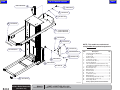
Water Sensor
Go To Page:
Refer to:
Page
Adjustment (Old) ................................. B-23
Adjustment (Current) ........................... B-24
Function and Location
Exploded Views / Part Numbers .......... E-1
The water sensor is located at the rear of the table prior to the inlet
of the pump. As water flows down thru the drain hose, it activates
the water sensor which starts the pump. Whenever the sensor
monitors water running past it the pump will remain activated.
www.midmark.com:
File Name
Serial Numbers DMM-1475-D/T Thru Present
*Use Water Sensor Replacement 003-1939-00
Serial Numbers DMM-1070-D/T Thru DMM-1474-D/T-06
When the sensor no longer detects water, the timer is activated
which continues to run the pump for 3 seconds. This allows any
remaining water to be purged out of the system.
*Use Water Sensor Replacement 003-1939-00
*Replacement instructions are provided with the part.
They are also available on documark.com,
or by clicking on the link in the blue box.
(Older version shown)
B-22
Models:
Water Sensor
© Midmark Corporation 2007 SF-1902
Serial Numbers:
Rev. 4/09
CMDT & CMDT-WS (45 & 60)
All
Back
Go To Table Of Contents
Next
Testing & Repair
Water Sensor
Go To Page:
Refer to:
Page
Section C: Access Procedures ............. C-1
Adjustment (Older version only)
Step 1: Remove back panel from column.
Refer to: Section C Back Panel
Step 2: Look for the LED light on water sensor.
Note: Water sensor light comes on when it detects water movement.
VA108600
LED Light
Green Light Stays On All The Time
Shows Power To The Sensor
Adjustment Screw
Step 3: Turn the adjustment screw clockwise until the LED light and pump turn on.
Step 4: Slowly continue turning the adjustment screw counterclockwise
for two to three additional turns after the light turns off.
Step 5: Run some water into the pump.
Note: It should cycle on and off as the water is drained.
If not, try readjusting the sensor. If it still isn't working,
replace the water sensor.
Models: CMDT & CMDT-WS (45 & 60)
Serial Numbers:
All
Water Sensor
© Midmark Corporation 2007 SF-1902
B-23
Rev. 4/09
Back
Go To Table Of Contents
Next
Testing & Repair
Water Sensor
Adjustment (Current version only)
Step 1: Remove back panel from column.
Refer to: Section C Back Panel
Go ToPage
Page:
Refer to:
Section C: Access Procedures ............. C-1
Step 2: Open small door on water sensor to access adjustment screw.
Adjust counter-clockwise to decrease sensitivity and clockwise to increase sensitivity.
Step 3: Run some water into the pump.
Note: It should cycle on and off as the water is drained.
If not, try readjusting the sensor. If it still isn't working,
replace the water sensor.
Water Sensor
B-24
© Midmark Corporation 2007 SF-1902 Rev. 2/22/12
Models:
Serial Numbers:
CMDT & CMDT-WS (45 & 60)
All
Back
Go To Table Of Contents
Next
Testing & Repair
Spray Nozzle and Hose Assembly
Refer to:
Page
Go To Page:
Exploded Views / Part Numbers .......... E-1
Check
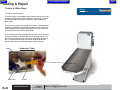
Step 1: If spray hose is leaking, replace with new
nozzle and hose assembly with 3" red fittings .
VA108700
Models:
Serial Numbers:
CMDT & CMDT-WS (45 & 60)
All
Water Sprayer
© Midmark Corporation 2007 SF-1902
B-25
Back
Go To Table Of Contents
Next
Testing & Repair
Scale
Go To Page:
Refer to:
Page
Calibrate Scale ............................B-27-B-29
Scale (Transformer) ............................. B-30
Function and Location
The scale which is optional on both the dry and wet tables incorporates four load sensors located under the table top surface.
Scale (Load Cells) ................................ B-31
Sca;e (Display) .................................... B-32
The scale provides a continuous weight that is accurate to + or - 0.1
lbs. The display is located on the front of the of the column near the
top.
Exploded Views / Part Numbers .......... E-1
www.midmark.com:
File Name
*Scale Transformer Replacement...003-1799-00
*Replacement instructions are provided with the part.
They are also available on midmark.com,
or by clicking on the link in the blue box.
Load Cell
Display
B-26
Scale
© Midmark Corporation 2007 SF-1902
Models:
Serial Numbers:
Accessory
Optional
Back
Go To Table Of Contents
Next
Testing & Repair
Scale
NOTE: 50 lb Weight is Required for Calibrating Scale.
Selections shown in graphics are factory default settings.
Refer to:
Page
Section C: Access Procedures ............ C-1
Calibration
Step 1: Lift back left corner of
table top to access
calibration button on
the PC board.
Step 2: Press the "CAL" button on the
PC board and lower table top
back in to position.
Step 3: Select "USA" (100%) or "CAN" (2% zero range) by pressing UNIT button.
Lock in selection by pressing ZERO button.
VA108800
C = Center of Zero
UNITS
lb
kg
ZERO
Continue on Next Page with Step 4
VA108900
Models:
Serial Numbers:
Accessory
Optional
Scale
(Calibration)
© Midmark Corporation 2007 SF-1902
B-27
Rev. 4/09
Back
Go To Table Of Contents
Next
Testing & Repair
Scale
Calibration - continued
Step 4: Select "lbs"[*] or "kg" by pressing UNIT button.
Lock in selection by pressing ZERO button.
Step 5: Select "RANGE" [*] (enable) or "norAng" (disable) by pressing
Note: To have both unit types available for use, select unit button
until the selection arrow is above both "lbs" and "kg", then lock in
selection by pressing ZERO button.
UNIT button. Lock in selection by pressing ZERO button.
C = Center of Zero
C = Center of Zero
lb
lb
kg
kg
UNITS
ZERO
ZERO
UNITS
VA109100
RANGE = 0-30 lbs by 0.1 lbs
30-70 lbs by 0.2 lbs
75-300 by 0.5 lbs
VA108900
Arrow Changes Selection Between "lbs" or "kg".
norAng= 0-300 lbs by 0.1 lbs
Step 6: Select "POLLED" [*] (polled) or "CONT" (continuous) by pressing
UNIT button. Lock in selection by pressing ZERO button.
Output Settings
POLLED = The Computer Requests the Output
by Sending the Scale a "CR" Character (OD HEX).
C = Center of Zero
lb
CONT = The Output is Automatically
Transmitted Every 0.5 Seconds.
kg
ZERO
UNITS
VA109200
[*] Denotes "FACTORY" setting
B-28
Scale
(Calibration)
© Midmark Corporation 2007 SF-1902
Models:
Serial Numbers:
Rev. 4/09
Accessory
Optional
Continue on Next Page with Step 7
Back
Go To Table Of Contents
Next
Testing & Repair
Scale
Go To Page:
Calibration - continued
Step 7: Select "nohold" (disabled) or "Hold" [*] (enabled) by
pressing UNIT button. Lock in selection by pressing ZERO button.
Step 8: To Establish Zero Reference Point, unload the
dead load count by pressing the ZERO button.
nohold = Weight will be Normal, but Unstable.
C = Center of Zero
C = Center of Zero
lb
UNITS
kg
lb
kg
C = Center of Zero
ZERO
lb
kg
ZERO
UNITS
ZERO
UNITS
VA109400
VA109300
Hold = Selecting Hold after 3 Seconds of Stable Weight
will Lock the Weight in after Weight is Removed from Scale.
Step 9: Press the UNIT button to toggle through calibration weights to 50.
Load 50 lb weight as evenly as possible.
When the amount stabilizes at 50lbs, press ZERO to span the scale.
Remove weight, calibration is completed.
C = Center of Zero
UNITS
lb
kg
ZERO
VA109500
[*] Denotes "FACTORY" setting
Models:
Serial Numbers:
Accessory
Optional
Scale
(Calibration)
© Midmark Corporation 2007 SF-1902
B-29
Rev. 2/22/12
Back
Go To Table Of Contents
Next
Testing & Repair
Scale (Transformer)
Go ToPage
Page:
Refer to:
Calibrate Scale ..................................... B-27
Test
Scale (Load Cells) ................................ B-31
Scale (Display) .................................... B-32
Step 1: Remove table top to access PC board for scale.
Section C: Access Procedures ............ C-1
Exploded Views / Part Numbers ............ E-1
Refer to: Section C Table Top
Scale Display
Load
Cells
Caution
When testing components
with power on use care to
prevent electrical shock.
PC Board
Step 3: Check for 12VDC output on
Step 2: Unplug transformer from PC board.
the end of transformer cable .
Reading
NOTE: If replacing the transformer, verify the black
wire with the faint white line is connected to the red wire.
B-30
Scale
(Transformer)
© Midmark Corporation 2007 SF-1902
Models:
Serial Numbers:
Rev. 2/22/12
Accessory
Optional
Status
Required Action
12 VDC
Transformer OK
< 12 VDC
Replace Transformer
Back
Go To Table Of Contents
Next
Testing & Repair
Scale (Load Cells)
Go To Page:
Refer to:
Page
Calibrate Scale ..................................... B-27
Test
Scale (Transformer) ............................. B-30
Scale (Display) .................................... B-32
Step 1: Remove table top to access load cells for scale.
Refer to: Section C Table Top
Load
Cells
Section C: Access Procedures ............ C-1
Exploded Views / Part Numbers ............ E-1
Scale Display
PC Board
Step 2: Unplug all four load cells at PC board.
Check each Load Cell...
Step 3: Plug in one load cell.
Press on cell to load.
Note: Verify each test shows up and down reading on display.
If not, replace bad load cell. If they all test ok, continue wiith Step 4.
Caution
When testing components
with power on use care to
prevent electrical shock.
Calibrate..
Step 4: Unplug one load cell at a time and claibrate with other three load cells connected.
Note: When the defective cell is removed, the unit will calibrate and weigh correctly.
Models:
Serial Numbers:
Accessory
Optional
Scale
(Load Cells)
© Midmark Corporation 2007 SF-1902 Rev. 2/22/12
B-31
Back
Go To Table Of Contents
Next
Testing & Repair
Scale (Display)
Step 3: Locate back of scale display (behind electrical box.
Verify wire harness from PC board is connected.
Check
Go ToPage
Page:
Refer to:
Calibrate Scale ..................................... B-27
Scale (Transformer) ............................. B-30
Scale (Load Cells) ................................ B-31
Top View
Section C: Access Procedures ............ C-1
Exploded Views / Part Numbers ............ E-1
Step 1: Unplug table from wall outlet.
Wire Harness
Connection
Step 2: Remove back panel from column.
Refer to: Section C Back Panel
VA1724i
B-32
Scale
(Display)
© Midmark Corporation 2007 SF-1902
Models:
Serial Numbers:
Rev. 2/22/12
Accessory
Optional
Back
Go To Table Of Contents
Section C
Access Procedures
Next
Go To Page:
Removing & Installing:
Page
Back Panel ........................................... C-2
Table Top .............................................. C-3
Safety Pan (Dry Table Only) ................. C-4
© Midmark Corporation 200x SF-xxxx
C-1
Back
Go To Table Of Contents
Next
Access Procedures
Back Panel
Removal
Step 1: Remove screws and washers.
Go To Page
Page:
Refer To:
Exploded Views / Part Numbers:
Removal/Installation
CMW* (O & S) ................................... E-2
CMDT* (60, WS-60, 45, WS-45) ......... E-3
Installation
Step 1: Install screws and washers.
Dry Tables
Wet Tables
VA109800
C-2
Back Panel
© Midmark Corporation 2007 SF-1902
Models:
Serial Numbers:
ALL
Back
Go To Table Of Contents
Next
Access Procedures
Table Top
Go To Page:
Refer To:
Page
Exploded Views / Part Numbers:
Removal/Installation
CMW* (O & S) ................................... E-2
CMDT* (60, WS-60, 45, WS-45) ......... E-3
Wet Tables
DryTables
Wet Table Top Removal
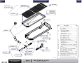
Step 1: Remove grate(s) and drain pan.
Note: Older model tables have one piece grate.
Dry Table Removal
Step 1: Remove mat and table top.
VA109900i
Wet Table Top Installation
Step 1: Install drain pan and grate(s).
Models:
Serial Numbers:
ALL
Dry Table Top Installation
Step 1: Install table top and mat.
Table Top
© Midmark Corporation 2007 SF-1902 Rev. 8/11
C-3
Back
Go To Table Of Contents
Next
Access Procedures
Safety Pan
Go To Page
Page:
Refer To:
Exploded Views / Part Numbers:
Removal/Installation
CMW* (O & S) ................................... E-2
Removal
Step 1: Lift mat off table top.
Lift table top off rubber mounts.
Removal
Step 2: Unplug scale connections
from PC board. (If Applicable)
Unscrew safety pan from
platform and remove.
Installation
Step 1: Screw safety pan to platform.
Plug scale connections
into PC board. (If applicable)
VA110000
Installation
Step 2: Seat table top on rubber mounts.
Place mat on table top.
C-4
Safety Pan
© Midmark Corporation 2007 SF-1902
Models:
Serial Numbers:
CMWO
CMWS
ALL
ALL
Back
Go To Table Of Contents
Section D
Wiring Diagrams
Next
Model
Dry Tables:
Page
Go To Page:
CMWO w/o Scale.................................. D-2
CMWS with Scale ................................. D-3
Wet Tables:
CMDT-45, CMDT-60 w/o Scale ............. D-4
Electrical Box (w/o scale) ..................... D-5
CMDT-WS-45, CMDT-WS-60 with Scale D-6
Electrical Box (with scale) ..................... D-7
© Midmark Corporation 2007 SF-1902
D-1
Back
Go To Table Of Contents
Next
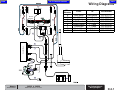
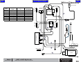
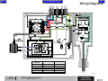
Wiring Diagrams
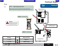
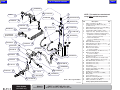
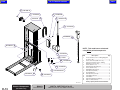
B
Wire
Harness
A
B
C
D
E
F
G
From:
To:
Part Number
Limit Switch
Limit Switch
Limit Switch
Rocker Switch
Control Box
Control Box
Control Box
Limit Switch
Limit Switch
Limit Switch
"T" Cable
"T" Cable
Limit Switchs
Outlet
015-0737-23
015-0737-23
015-0737-23
015-2215-00
015-2218-00
015-2207-00
015-2186-00
Limit Switches
A
Rocker Switches
C
D
Control Box
E
F
"T" Cable
Actuator
G
Foot Control
D-2
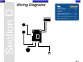
Dry Table w/o Scale
Wiring Diagram
© Midmark Corporation 2007 SF-1902 Rev. 3/08
Models:
Serial Numbers:
CMWO & CMWS
DMM-1280-05 thru DMM-1450-06
Back
Go To Table Of Contents
Next
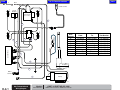
Wiring Diagrams
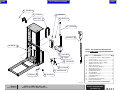
B
Wire
Harness
A
B
C
D
E
F
G
Limit Switches
A
Rocker Switches
C
From:
To:
Part Number
Limit Switch
Limit Switch
Limit Switch
Rocker Switch
Control Box
Control Box
Control Box
Limit Switch
Limit Switch
Limit Switch
"T" Cable
"T" Cable
Limit Switchs
Outlet
015-0737-23
015-0737-23
015-0737-23
015-2215-00
015-2218-00
015-2207-00
015-2186-00
D
Control Box
E
F
"T" Cable
Actuator
G
Foot Control
Models:
Serial Numbers:
CMWO & CMWS
DMM-1451-06 thru Present
Dry Table w/o Scale
Wiring Diagram
© Midmark Corporation 2007 SF-1902 Rev. 3/08
D-2.1
Back
Go To Table Of Contents
Next
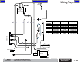
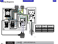
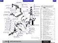
Wiring Diagrams
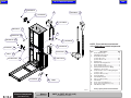
A
C.
N.C.
Rocker
Switches
GREEN
C
ORANGE
ORANGE
RED
C.
N.C.
015-0737-23
015-0737-23
015-0737-23
015-2200-00
015-2215-00
015-2218-00
015-2207-00
029-4142-00
C.
Limit Switch
Limit Switch
Limit Switch
Scale Display
"T" Cable
"T" Cable
Limit Switchs
Outlet
N.C.
Limit Switch
Limit Switch
Limit Switch
PC Board
Rocker Switch
Control Box
Control Box
Control Box
C.
Part Number
N.C.
To:
B
Scale Display
Load Cells
From:
Limit Switches
Wire
Harness
A
B
C
D
E
F
G
H
YELLOW (103")
PC
Board
BROWN
E
BLUE
D
Control Box
F
"T" Cable
G
Actuator
WHITE
BLACK
GREEN
BLACK
WHITE
GREEN
Scale
Transformer
H
H
Foot Control
D-3
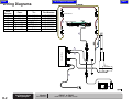
Dry Table with Scale
Wiring Diagram
© Midmark Corporation 2007 SF-1902 Rev. 1/11
Models:
Serial Numbers:
CMWO & CMWS
DMM-1280-05 thru DMM-1450-06
VA100200i
Back
Go To Table Of Contents
Next
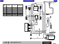
Wiring Diagrams
Limit Switches
Load Cells
B
Scale Display
A
Rocker
Switches
C
PC
Board
Wire
Harness
A
B
C
D
E
F
G
H
From:
To:
Part Number
Limit Switch
Limit Switch
Limit Switch
PC Board
Rocker Switch
Control Box
Control Box
Control Box
Limit Switch
Limit Switch
Limit Switch
Scale Display
"T" Cable
"T" Cable
Limit Switchs
Outlet
015-0737-23
015-0737-23
015-0737-23
015-2200-00
015-2215-00
015-2218-00
015-2207-00
029-4142-00
D
E
Control Box
F
G
"T" Cable
Actuator
Scale
Transformer
H
H
Foot Control
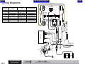
Models:
Serial Numbers:
CMWO & CMWS
DMM-1451-06 thru Present
Dry Table with Scale
Wiring Diagram
© Midmark Corporation 2007 SF-1902 Rev. 1/11
D-3.1
Back
Go To Table Of Contents
Next
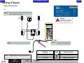
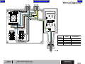
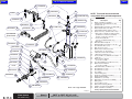
Wiring Diagrams
From:
To:
Part Number
Control Box
Electrical Box
Pump
Control Box
Control Box
Control Box
Electrical Box
Limit Switch
Water Sensor
Electrical Box
Timer
Hand Control
Electrical Box
Outlet
015-2288-00
002-1179-00
015-2289-00
015-2275-00
015-2285-00
015-2270-00
015-1139-01
Refer to
Electrical
Box
(w/o Scale)
Control Box
Limit Switch
Wire
Harness
A
B
C
D
E
F
G
Hand
Control
Actuator
Water Sensor
Pump
D-4
Wet Table w/o Scale
Wiring Diagram
Models:
Serial Numbers:
© Midmark Corporation 2007 SF-1902 Rev. 3/08 Rev. 7/5/12
CMDT & CMDT-WS (45 & 60)
DMM-1070-D/T-05 thru DMM-1474-D/T-06
Back
Go To Table Of Contents
Next
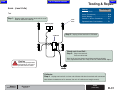
Wiring Diagrams
Hand
Control
Refer to
Electrical
Box
(w/o Scale)
E
D
F
G
Wire
Harness
A
B
C
D
E
F
G
C
From:
To:
Part Number
Control Box
Electrical Box
Pump
Control Box
Control Box
Control Box
Electrical Box
Limit Switch
Water Sensor
Electrical Box
Timer
Hand Control
Electrical Box
Outlet
015-2288-00
015-2262-00
015-2289-00
015-2275-00
015-2285-00
015-2270-00
015-1139-01
Control Box
Limit Switch
B
A
Actuator
Water Sensor
Pump
Models:
Serial Numbers:
CMDT & CMDT-WS (45 & 60)
DMM-1475-D/T-06 thru DMM-1237-D/T-08
Wet Table w/o Scale
Wiring Diagram
© Midmark Corporation 2007 SF-1902 Rev. 7/5/12
D-4.1
Back
Go To Table Of Contents
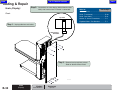
Next
Wiring Diagrams
To:
Part Number
Limit Switch
Water Sensor
Electrical Box
Timer
Hand Control
Electrical Box
Outlet
015-2288-00
015-2436-00
015-2289-00
015-2275-00
015-2285-00
015-2270-00
015-1139-01
Refer to
Electrical
Box
(w/o Scale)
B
E
D
F
G
C
Control Box
Limit Switch
Wire
From:
Harness
A
Control Box
B
Electrical Box
C
Pump
D
Control Box
E
Control Box
F
Control Box
G
Electrical Box
Hand
Control
A
Actuator
Water Sensor
Pump
D-4.2
Wet Table w/o Scale
Wiring Diagram
© Midmark Corporation 2007 SF-1902 Rev. 7/5/12
Models:
Serial Numbers:
CMDT & CMDT-WS (45 & 60)
DMM-1238-D/T-08 thru Present
Back
Go To Table Of Contents
Next
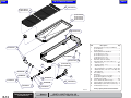
Wiring Diagrams
A
B
C
D
GFI Receptacle
Water
Sensor
Timer
Wire
Harness
A
B
C
D
E
From:
Part Number
Water Sensor
Pump Motor
Timer Cord
Power Cord
Electrical Cord
015-2436-00
015-2289-00
015-2275-00
015-2270-00
015-1139-01
E
Models:
Serial Numbers:
CMDT & CMDT-WS (45 & 60)
DMM-1070-D/T-05 thru DMM-1xxx-D/T-09
Electrical Box
(units w/o scale)
© Midmark Corporation 2007 SF-1902 Rev. 5/08
D-5
Back
Go To Table Of Contents
Next
Wiring Diagrams
C
B
D
RED
A
RED
GREEN /
YELLOW
GREEN /
YELLOW
RED
RED
Wire
Harness
A
B
C
D
E
From:
Part Number
Water Sensor
Pump Motor
Timer Cord
Power Cord
Electrical Cord
015-2436-00
015-2289-00
015-2275-00
015-2270-00
015-1139-01
E
VA150201i
D-5.1
Electrical Box
(units w/o scale)
© Midmark Corporation 2007 SF-1902
Models:
Serial Numbers:
CMDT & CMDT-WS (45 & 60)
V730066 thru Present
Back
Go To Table Of Contents
Next
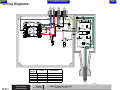
Wiring Diagrams
PC Board
PC Board
Control Box
Electrical Box
Control Box
Pump
Control Box
Electrical Box
Electrical Box
Scale Display
Hand Control
Limit Switch
Electrical Box
Electrical Box
Timer
Outlet
015-2279-00
015-2200-00
015-2285-00
015-2288-00
015-2270-00
015-2289-00
015-2275-00
015-1139-01
Scale
Display
Refer to
Electrical Box
(w/o Scale)
Control Box
PC
Board
Limit Switch
Part Number
Load Cell
To:
Load Cell
From:
Load Cell
Wire
Harness
A
B
C
D
E
F
G
H
Load Cell
Hand Control
Actuator
Water Sensor
Pump
Models:
Serial Numbers:
CMDT & CMDT-WS (45 & 60)
DMM-1070-D/T-05 thru DMM-1474-D/T-06
Wet Table with Scale
Wiring Diagram
© Midmark Corporation 2007 SF-1902 Rev. 7/5/12
D-6
Back
Go To Table Of Contents
Next
Wiring Diagrams
Scale
Display
Load Cell
Load Cell
Hand Control
Refer to
Electrical Box
(w/o Scale)
F
BROWN
Control Box
B
BLUE
C
A
Wire
Harness
A
B
C
D
E
F
G
H
I
Limit Switch
Load Cell
Load Cell
G
H
D
Actuator
E
Water
Sensor
I
Pump
VA104300i
D-6.1
Wet Table with Scale
Wiring Diagram
© Midmark Corporation 2007 SF-1902 Rev. 7/5/12
Models:
Serial Numbers:
CMDT & CMDT-WS (45 & 60)
DMM-1475-D/T-06 thru DMM-1237-D/T-08
From:
To:
Part Number
PC Board
Water Sensor
Control Box
Electrical Box
Control Box
Pump
PC Board
Control Box
Electrical Box
Scale Display
Electrical Box
Hand Control
Limit Switch
Electrical Box
Electrical Box
Electrical Box
Timer
Outlet
015-2200-00
015-2373-00
015-2285-00
015-2288-00
015-2270-00
015-2289-00
015-2279-00
015-2275-00
015-1139-01
Back
Go To Table Of Contents
Next
Wiring Diagrams
PC Board
Water Sensor
Control Box
Electrical Box
Control Box
Pump
PC Board
Control Box
Electrical Box
Scale Display
Electrical Box
Hand Control
Limit Switch
Electrical Box
Electrical Box
Electrical Box
Timer
Outlet
015-2200-00
015-2436-00
015-2285-00
015-2288-00
015-2270-00
015-2289-00
015-2279-00
015-2275-00
015-1139-01
Refer to
Electrical Box
(w/o Scale)
F
G
Limit Switch
A
B
C
D
E
F
G
H
I
Scale
Display
C
A
Control Box
BROWN
B
BLUE
Part Number
Load Cell
To:
Load Cell
From:
Load Cell
Wire
Harness
Load Cell
Hand Control
H
D
Actuator
E
Water
Sensor
I
Pump
VA104301i
Models:
Serial Numbers:
CMDT & CMDT-WS (45 & 60)
DMM-1238-D/T-08 thru Present
Wet Table with Scale
Wiring Diagram
© Midmark Corporation 2007 SF-1902 Rev. 7/5/12
D-6.2
Back
Go To Table Of Contents
Next
Wiring Diagrams
D
C
B
A
E
BLACK
GREEN / YELLOW
BLACK
BLUE
BROWN
8
7
5
6
OUT
3
Water
Sensor
Timer
4
BLACK
BLACK
PWR
BLUE
4
2
BROWN
BLACK
5
GREEN
WHITE
0
6
MODE
D
GFI Receptacle
WHITE
BLACK
RANGE
1S
BLACK
WHITE
GREEN / YELLOW
9
10
11
1
2
3
WHITE
BROWN
GREEN
BLUE
BROWN
BLACK
BLUE
WHITE
BLACK
WHITE
BLACK
JUMPER
WHITE
GREEN
BLACK
JUMPER
BLACK
BLACK
Wire
Harness
A
B
C
D
E
F
WHITE
BLACK
WHITE
Scale
Receptacle
F
VA100500i
Scale
Transformer
D-7
Electrical Box
(units with scale)
© Midmark Corporation 2007 SF-1902 Rev. 5/08
Models:
Serial Numbers:
CMDT & CMDT-WS (45 & 60)
DMM-1070-D/T-05 thru DMM-1xxx-D/T-09
From:
Part Number
Water Sensor
Scale
Pump Motor
Timer Cord
Power Cord
Electrical Cord
015-2436-00
015-2279-01
015-2289-00
015-2275-00
015-2270-00
015-1139-01
Back
Go To Table Of Contents
Next
Wiring Diagrams
A
D
RED
B
C
E
RED
RED
GREEN /
YELLOW
GREEN /
YELLOW
GREEN /
YELLOW
GREEN / YELLOW
RED
RED
BLACK / WHITE STRIPE
BLACK / WHITE
STRIPE
RED
GREEN /
YELLOW
Wire
Harness
A
B
C
D
E
F
From:
Part Number
Water Sensor
Scale
Pump Motor
Timer Cord
Power Cord
Electrical Cord
015-2436-00
015-2279-01
015-2289-00
015-2275-00
015-2270-00
015-1139-01
F
VA150101i
Models:
Serial Numbers:
CMDT & CMDT-WS (45 & 60)
V730066 thru Present
Electrical Box
(units with scale)
© Midmark Corporation 2007 SF-1902
D-7.1
Back
Go To Table Of Contents
Next
Back
Section E
Go To Table Of Contents
Exploded Views &
Parts Lists
Next
Go To Page:
Model:
Page
CMWO / CMWS: .................................. E-2
CMDT-**, CMDT-**-** ........................... E-3
© Midmark Corporation 2007
SF-1902
E-1
Back
Go To Table Of Contents
Next
CMW* (O & S)
Lift Mechanism: ................... E-6*
Covers and Fasteners: ........ E-4*
Column Electrical
Components: ....................... E-7*
Column Roller
Mechanism: .......................... E-5*
Tabletop Electrical
Components: ....................... E-8*
NOTE: This model was maufactured using both White
and Pebble Grey painted components, please make sure
that you are refering to the correct corresponding page.
E-2
© Midmark Corporation 2007 SF-1902 Rev. 4/09
* Indicates multiple pages due to a model / serial number break for the parts illustration
Back
Go To Table Of Contents
Next
CMDT- (60,WS-60, 45, WS-45)
Optional Features
Grill Cover ................... E-xx
Electrical Box: ...................... E-15*
Electrical Box w/ Scale: ....... E-16*
Water System: ...................... E-11*
Lift Mechanism: ................... E-6*
Column Roller
Mechanism: .......................... E-9*
Electrical Components: ...... E-13*
Covers and Fasteners: ........ E-10*
Table Top Components: ...... E-12*
Scale Components: ............. E-14*
NOTE: This model was maufactured using both White
and Pebble Grey painted components, please make sure
that you are refering to the correct corresponding page.
* Indicates multiple pages due to a model / serial number break for the parts illustration
E-3
© Midmark Corporation 2007 SF-1902 Rev. 10/08
Back
Go To Table Of Contents
5
002-1092-00
Next
1
a) 050-7182-00
b) 050-7182-01
2
050-7125-00-393
3
053-0858-04
4
040-0010-144
6
050-7150-00
042-0014-51
045-0001-141
9
NOTE: This model was maufactured
using White painted components.
10
8
041-0006-03
050-7145-00-393
Item
7
1
050-7144-00-393
11
2
3
4
016-0945-04
19
053-0013-00
17
040-0010-170
050-7102-00
5
6
7
8
9
10
11
12
13
14
15
16
18
12
053-1813-00
13
041-0312-11
16
14
15
040-0010-169
17
18
19
016-1133-00
VA110100i
E-4
Covers and Fasteners
(dry tables only)
© Midmark Corporation 2007 SF-1902 Rev. 11/09
Models:
Serial Numbers:
CMWO & CMWS
DMM-1280-05 thru DMM-1450-06
Description
Qty.
Column Cover:
a) units withscale ......................................... 1
b) units without scale ................................... 1
Back Cover ................................................... 1
Nylon Washer (#10) ................................... 13
Stainless Steel Round Head Screw
(#10-32 x 3/4") ........................................... 13
Stat-Mat Kit .................................................. 1
Stainless Steel Tabletop Cover ................... 1
PC Board Cover (units with scale only) ..... 1
ESNA Nut (#6-32) [units with scale only] ... 2
Shoulder Bolt (#10-32 x 1" x 1") ................. 4
Washer ......................................................... 4
Safety Pan ................................................... 1
Stainless Steel Leg Cover ........................... 1
Truss Head Screw (#10-32 x 1/2") ............ 4
Nut (5/16-18) ............................................... 2
Leveling Foot (5/16"-18) .............................. 2
Stainless Steel Hex Socket Flat Head
Screw (#10-32 x 1/2") [apply thread
locking adhesive] ......................................... 8
Skid Pad ....................................................... 2
Cover Edge Guard ....................................... 1
Bumper (units without scales only) ............ 12
Always Specify Model & Serial Number
Back
Go To Table Of Contents
5
002-1092-00
061-0860-01
Next
1
a) 050-7182-00
b) 050-7182-01
2
050-7125-00-393
18
3
053-0858-04
4
6
050-7150-00
042-0014-51
045-0001-141
041-0006-03
040-0010-144
9
NOTE: This model was maufactured
using White painted components.
10
8
Item
050-7145-00-393
050-7144-00-393
016-0945-04
1
7
11
2
3
4
19
20
053-0013-00
17
040-0010-170
12
053-1813-00
13
041-0312-11
050-7102-00
5
6
7
8
9
10
11
12
13
14
15
16
16
14
15
17
18
19
20
040-0010-169
016-1133-00
Description
Qty.
Column Cover:
a) units withscale ......................................... 1
b) units without scale ................................... 1
Back Cover ................................................... 1
Nylon Washer (#10) ................................... 13
Stainless Steel Round Head Screw
(#10-32 x 3/4") ........................................... 13
Stat-Mat ........................................................ 1
Stainless Steel Tabletop Cover ................... 1
PC Board Cover (units with scale only) ....... 1
ESNA Nut (#6-32) [units with scale only] .... 2
Shoulder Bolt (#10-32 x 1" x 1") .................. 4
Washer ......................................................... 4
Safety Pan .................................................... 1
Stainless Steel Leg Cover ........................... 1
Truss Head Screw (#10-32 x 1/2") .............. 4
Nut (5/16-18) ................................................ 2
Leveling Foot (5/16"-18) .............................. 2
Stainless Steel Hex Socket Flat Head
Screw (#10-32 x 1/2") [apply thread
locking adhesive] ......................................... 8
Skid Pad ....................................................... 2
Midmark Logo Nameplate ............................ 1
Cover Edge Guard ....................................... 1
Bumper (units without scales only) ............ 12
Always Specify Model & Serial Number
VA102200i
Models:
Serial Numbers:
CMWO & CMWS
DMM-1451-06 thru DMM-1908-08
Covers and Fasteners
(dry tables only)
© Midmark Corporation 2007 SF-1902 Rev. 11/09
E-4.1
Back
Go To Table Of Contents
5
002-1092-00
061-0860-01
Next
1
a) 050-7182-00
b) 050-7182-01
2
050-7125-00-216
18
3
053-0858-04
4
6
050-7150-00
042-0014-51
045-0001-141
041-0006-03
040-0010-144
9
NOTE: This model was maufactured
using Pebble Grey painted components.
10
8
Item
050-7145-00-216
050-7144-00-216
016-0945-04
7
1
11
2
3
4
19
20
053-0013-00
17
040-0010-170
053-1813-00
13
041-0312-11
050-7102-00
5
6
7
8
9
10
11
12
13
14
15
16
12
16
14
15
17
18
19
20
040-0010-169
016-1133-00
VA102200i
E-4.2
Covers and Fasteners
(dry tables only)
© Midmark Corporation 2007 SF-1902 Rev. 11/09
Models:
Serial Numbers:
CMWO & CMWS
DMM-1909-08 thru DMM-2028-09
Description
Qty.
Column Cover:
a) units withscale ......................................... 1
b) units without scale ................................... 1
Back Cover ................................................... 1
Nylon Washer (#10) ................................... 13
Stainless Steel Round Head Screw
(#10-32 x 3/4") ........................................... 13
Stat-Mat Kit .................................................. 1
Stainless Steel Tabletop Cover ................... 1
PC Board Cover (units with scale only) ..... 1
ESNA Nut (#6-32) [units with scale only] ... 2
Shoulder Bolt (#10-32 x 1" x 1") ................. 4
Washer ......................................................... 4
Safety Pan ................................................... 1
Stainless Steel Leg Cover ........................... 1
Truss Head Screw (#10-32 x 1/2") ............ 4
Nut (5/16-18) ............................................... 2
Leveling Foot (5/16"-18) .............................. 2
Stainless Steel Hex Socket Flat Head
Screw (#10-32 x 1/2") [apply thread
locking adhesive] ......................................... 8
Skid Pad ....................................................... 2
Midmark Logo Nameplate ............................ 1
Cover Edge Guard ....................................... 1
Bumper (units without scales only) ............ 12
Always Specify Model & Serial Number
Back
Next
Go To Table Of Contents
5
002-1092-00
061-0860-01
1
a) 002-1811-00
b) 002-1811-01
2
050-7125-00-216
18
3
045-0001-31
4
6
050-7150-00
042-0014-57
045-0001-141
041-0006-03
9
NOTE: This model was maufactured
using Pebble Grey painted components.
10
8
050-7145-00-216
050-7730-00-216
040-0010-109
Item
7
1
11
2
3
4
016-0945-04
5
6
7
8
9
10
11
12
13
14
15
16
19
13
119891
17
053-1813-00
4
C1269
050-7729-00-216
12
16
14
15
040-0010-106
17
18
19
016-1133-00
Description
Qty.
Column Cover:
a) units with scale (shown) .......................... 1
b) units without scale ................................... 1
Back Cover ................................................... 1
External Tooth Lockwasher (#10) ................ 1
Round Head Screw
(#10-24 x 3/8") ........................................... 17
Stat-Mat Kit .................................................. 1
Stainless Steel Tabletop Cover ................... 1
PC Board Cover (units with scale only) ....... 1
ESNA Nut (#6-32) [units with scale only] .... 2
Shoulder Bolt (#10-32 x 1" x 1 1/4") ............ 4
Washer ......................................................... 4
Safety Pan .................................................... 1
Frame Bottom Cover .................................... 1
Bumper (units without scales only) ............ 12
Nut (5/16-18) ................................................ 2
Leveling Foot (5/16"-18) .............................. 2
Stainless Steel Hex Socket Flat Head
Screw (#10-32 x 1/2") [apply thread
locking adhesive] ......................................... 8
Skid Pad ....................................................... 2
Midmark Logo Nameplate ............................ 1
Cover Edge Guard ....................................... 1
Always Specify Model & Serial Number
VA1503i
Models:
Serial Numbers:
CMWO & CMWS
V730066 thru V962624
Covers and Fasteners
(dry tables only)
© Midmark Corporation 2007 SF-1902 Rev.4/14
E-4.3
5
002-1092-00
061-0860-01
1
a) 002-1811-00
b) 002-1811-01
2
050-7125-00-216
18
3
045-0001-31
4
042-0014-57
9
6
050-7150-00
045-0001-141
025-0042-09
8
041-0006-03
040-0010-109
NOTE: This model was maufactured
using Pebble Grey painted components.
10
20
Item
050-7145-00-216
050-7730-00-216
016-0945-04
1
7
11
2
3
4
5
6
7
8
9
10
11
12
13
14
15
16
19
13
119891
17
053-1813-00
4
C1269
050-7729-00-216
12
16
14
15
17
18
19
20
040-0010-106
016-1133-00
VA150301i
E-4.4
Covers and Fasteners
(dry tables only)
© Midmark Corporation 2007 SF-1902 Rev.4/14
Models:
Serial Numbers:
CMWO & CMWS
V730066 thru Present
Description
Qty.
Column Cover:
a) units with scale (shown) .......................... 1
b) units without scale ................................... 1
Back Cover ................................................... 1
External Tooth Lockwasher (#10) ................ 1
Round Head Screw
(#10-24 x 3/8") ........................................... 17
Stat-Mat Kit .................................................. 1
Stainless Steel Tabletop Cover ................... 1
PC Board Cover (units with scale only) ....... 1
ESNA Nut (#6-32) [units with scale only] .... 2
Shoulder Bolt (#10-32 x 1" x 1 1/4") ............ 4
Washer ......................................................... 4
Safety Pan .................................................... 1
Frame Bottom Cover .................................... 1
Bumper (units without scales only) ............ 12
Nut (5/16-18) ................................................ 2
Leveling Foot (5/16"-18) .............................. 2
Stainless Steel Hex Socket Flat Head
Screw (#10-32 x 1/2") [apply thread
locking adhesive] ......................................... 8
Skid Pad ....................................................... 2
Midmark Logo Nameplate ............................ 1
Cover Edge Guard ....................................... 1
Compression Spring .................................... 4
Always Specify Model & Serial Number
Back
Go To Table Of Contents
Next
8
4
6
N.L.A.
3
7
2
17
040-0312-06
045-0001-27
045-0001-143
1
N.L.A.
7
N.L.A.
8
9
N.L.A.
N.L.A.
11
N.L.A.
N.L.A.
12
NOTE: This model was maufactured
using White painted components.
N.L.A.
Item
N.L.A.
5
10
14
15
16
1
2
3
4
5
6
7
8
9
10
11
12
13
14
15
16
17
N.L.A.
045-0001-142
016-0149-30
016-1141-02
041-0750-03
13
(*) N.L.A. denotes "No Longer Available
Description
Qty.
Tabletop Platform Weldment ....................... 1
Washer (5/16") ............................................. 8
Lockwasher (5/16") ...................................... 8
Hex Bolt (5/16"-18 x 1") ............................... 8
Column Weldment ....................................... 1
L.H. Roller Bracket ....................................... 1
Screw ......................................................... 16
Nylon Slide Pads .......................................... 8
Slide Pads Mounting Bracket ...................... 4
R.H. Roller Bracket ...................................... 1
Set Screw ................................................... 16
Nut ................................................................ 4
Nut (3/4"-16) ................................................. 4
Lockwasher (3/4") ........................................ 6
Bronze Bushing ............................................ 4
Radial Bearing Dia Roller (1-7/8") ............... 4
Canis Major Decal ........................................ 1
Always Specify Model & Serial Number
VA103500i
Models:
Serial Numbers:
CMWO & CMWS
DMM-1280-05 thru DMM-1422-06
Column Roller Mechanism
(dry tables only)
© Midmark Corporation 2007 SF-1902
E-5
Back
Go To Table Of Contents
050-7138-00-393
4
6
3
2
15
040-0312-06
045-0001-27
045-0001-143
1
061-0990-00
10
Next
030-1724-00-393
016-1141-01
9
016-0149-10
NOTE: This model was maufactured
using White painted components.
030-1711-00-393
8
5
7
041-0375-14
12
13
14
Item
050-7138-01-393
045-0001-142
016-0149-30
016-1141-02
041-0750-03
1
2
3
4
5
6
7
8
9
10
11
12
13
14
15
11
Description
Always Specify Model & Serial Number
VA102300i
E-5.1
Column Roller Mechanism
(dry tables only)
© Midmark Corporation 2007 SF-1902
Rev. 10/08
Models:
Serial Numbers:
CMWO & CMWS
DMM-1423-06 thru DMM-1908-08
Qty.
Tabletop Platform Weldment ....................... 1
Washer (5/16") ............................................. 8
Lockwasher (5/16") ...................................... 8
Hex Bolt (5/16"-18 x 1") .............................. 8
Column Weldment ....................................... 1
L.H. Roller Bracket (sold as bracket only,
[assembled for illustration purposes only]) .. 1
R.H. Roller Bracket ...................................... 1
Nut (3/8"-24) ................................................. 4
Bronze Bushing ............................................ 4
Column Roller .............................................. 4
Nut (3/4"-16) ................................................. 6
Lockwasher (3/4") ........................................ 6
Oilite Bushing ............................................... 6
Radial Bearing Dia Roller (1-7/8") ............... 6
Canis Major Decal ........................................ 1
Back
Go To Table Of Contents
050-7138-00-216
4
6
3
2
15
Next
045-0001-27
045-0001-143
1
061-0990-00
10
040-0312-06
030-1724-00-216
016-1141-01
9
016-0149-10
NOTE: This model was maufactured
using Pebble Grey painted components.
030-1711-00-216
8
5
7
041-0375-14
12
13
14
Item
050-7138-01-216
045-0001-142
016-0149-30
7
8
9
10
11
12
13
14
15
016-1141-02
041-0750-03
1
2
3
4
5
6
11
Description
Qty.
Tabletop Platform Weldment ....................... 1
Washer (5/16") ............................................. 8
Lockwasher (5/16") ...................................... 8
Hex Bolt (5/16"-18 x 1") .............................. 8
Column Weldment ....................................... 1
L.H. Roller Bracket (sold as bracket only,
[assembled for illustration purposes only]) .. 1
R.H. Roller Bracket ...................................... 1
Nut (3/8"-24) ................................................. 4
Bronze Bushing ............................................ 4
Column Roller .............................................. 4
Nut (3/4"-16) ................................................. 6
Lockwasher (3/4") ........................................ 6
Oilite Bushing ............................................... 6
Radial Bearing Dia Roller (1-7/8") ............... 6
Canis Major Decal ........................................ 1
Always Specify Model & Serial Number
VA102300i
Models:
Serial Numbers:
CMWO & CMWS
DMM-1909-08 thru DMM-2028-09
Column Roller Mechanism
(dry tables only)
© Midmark Corporation 2007 SF-1902 Rev. 4/09
E-5.2
Back
Next
Go To Table Of Contents
050-7138-00-216
2
3
1
040-0312-86
4
061-0990-00
6
030-1862-00-216
016-1141-01
8
016-0149-10
7
030-1852-00-216
9
5
11
12
050-7138-01-216
NOTE: This model was maufactured
using Pebble Grey painted components.
10
Item
045-0001-142
1
2
016-0149-30
3
4
5
6
7
8
9
10
11
12
016-1141-02
13
VA1504i
13
Description
Qty.
Canis Major Decal ........................................ 1
L.H. Roller Bracket (sold as bracket only,
[assembled for illustration purposes only]) .. 1
Hex Bolt (5/16"-18 x 1") .............................. 8
Table Frame Weldment, Dry 45" ................. 1
Tower Frame Weldment .............................. 1
Column Roller(includes item 7) .................... 4
• Nut (3/8"-24) .............................................. 6
Bronze Bushing ............................................ 4
R.H. Roller Bracket ...................................... 1
Lockwasher (3/4") ........................................ 6
Oilite Bushing ............................................... 6
Radial Bearing Dia Roller, 1-7/8"
(includes item 12) ......................................... 6
• Nut (3/4"-16) .............................................. 6
Always Specify Model & Serial Number
E-5.3
Column Roller Mechanism
(dry tables only)
© Midmark Corporation 2007 SF-1902
Models:
CMWO & CMWS
Serial Numbers:
V730066 thru Present
Back
Go To Table Of Contents
12
016-1135-00
5
15
Next
016-1134-00
13
13
122357
14
041-0375-10
11
14
10
042-0014-50
6
7
3
6
4
030-1720-00-393
040-0010-31
053-1821-00
8
9
NOTE: This model was maufactured
using White painted components.
9
3
045-0001-00
Item
1
2
1
041-0010-10
8
9
042-0638-00
050-7097-00
9
2
3
4
5
6
7
8
9
10
11
12
13
14
15
5
Part of
Actuator
Description
Qty.
24 Volt Lift Actuator (refer to "Electrical
Components") .......................................... Ref
ESNA Nut (#10-32) ...................................... 4
Washer (#10) ............................................... 8
Socket Hd. Cap Screw (#10-32 x 1 1/2") .... 4
Actuator Guide Angle ................................... 2
Bearing Block ............................................... 2
Upper Actuator Mounting Bracket ............... 1
Quick Release Pin ....................................... 2
Flange Bushing (comes with actuator) ....... 4
Cap Screw (3/8"-16) ..................................... 1
ESNA Nut (3/8"-16") .................................... 1
Idler Sprocket ............................................... 1
Drive Chain (#40 [includes item 14) ............ 1
• Connector Link Assembly (#40) ................ 2
Keps Lock Nut (#10-32) ............................... 6
Always Specify Model & Serial Number
VA102500i
Models:
Serial Numbers:
CMWO & CMWS
DMM-1280-05 thru DMM-1453-06
Lift Mechanism
(dry tables only)
© Midmark Corporation 2007 SF-1902 Rev. 5/08
E-6
Back
Go To Table Of Contents
12
016-1135-00
5
15
Next
016-1134-00
13
13
122357
14
041-0375-10
11
14
10
042-0014-50
6
7
3
6
4
030-1720-00-393
040-0010-31
053-1821-00
8
9
NOTE: This model was maufactured
using White painted components.
9
3
045-0001-00
Item
1
2
8
9
2
3
4
5
6
7
8
9
10
11
12
13
14
15
042-0638-00
050-7097-00
9
1
041-0010-10
5
Part of
Actuator
Description
24 Volt Lift Actuator (refer to "Electrical
Components") .......................................... Ref
ESNA Nut (#10-32) ...................................... 4
Washer (#10) ............................................... 8
Socket Hd. Cap Screw (#10-32 x 1 1/2") .... 4
Actuator Guide Angle ................................... 2
Bearing Block ............................................... 2
Upper Actuator Mounting Bracket ............... 1
Quick Release Pin ....................................... 2
Flange Bushing (comes with actuator) ....... 4
Cap Screw (3/8"-16") ................................... 1
ESNA Nut (3/8"-16") .................................... 1
Idler Sprocket ............................................... 1
Drive Chain (#40 [includes item 14) ............ 1
• Connector Link Assembly (#40) ................ 2
Keps Lock Nut (#10-32) ............................... 6
Always Specify Model & Serial Number
VA103300i
E-6.1
Models:
Lift Mechanism
(dry & wet tables)
© Midmark Corporation 2007 SF-1902
Serial Numbers:
Rev. 10/08
Qty.
CMWO & CMWS
CMDT & CMDT-WS (45 & 60)
DMM-1454-06 thru DMM-1908-08
DMM-1070-D/T-05 thru DMM-1241-D/T-08
Back
Go To Table Of Contents
12
016-1135-00
5
15
Next
016-1134-00
13
13
122357
14
041-0375-10
11
14
10
042-0014-50
6
7
3
6
4
030-1720-00-216
040-0010-31
053-1821-00
8
9
NOTE: This model was maufactured
using Pebble Grey painted components.
9
3
045-0001-00
1
2
Item
041-0010-10
8
9
2
3
4
5
6
7
8
9
10
11
12
13
14
15
042-0638-00
050-7097-00
9
1
5
Part of
Actuator
VA103300i
Models:
Serial Numbers:
CMWO & CMWS
DMM-1909-08 thru DMM-2028-09
CMDT & CMDT-WS (45 & 60)
DMM-1242-D/T-08 thru DMM-1288-D/T-09
Description
Qty.
24 Volt Lift Actuator (refer to "Electrical
Components") .......................................... Ref
ESNA Nut (#10-32) ...................................... 4
Washer (#10) ............................................... 8
Socket Hd. Cap Screw (#10-32 x 1 1/2") .... 4
Actuator Guide Angle ................................... 2
Bearing Block ............................................... 2
Upper Actuator Mounting Bracket ............... 1
Quick Release Pin ....................................... 2
Flange Bushing (comes with actuator) ....... 4
Cap Screw (3/8"-16") ................................... 1
ESNA Nut (3/8"-16") .................................... 1
Idler Sprocket ............................................... 1
Drive Chain (#40 [includes item 14) ............ 1
• Connector Link Assembly (#40) ................ 2
Keps Lock Nut (#10-32) ............................... 6
Always Specify Model & Serial Number
Lift Mechanism
(dry & wet tables)
© Midmark Corporation 2007 SF-1902 Rev. 4/09
E-6.2
Back
Next
Go To Table Of Contents
12
016-1135-00
5
15
13
122357
041-0375-10
016-1134-00
13
14
11
14
042-0007-12
10
042-0014-50
6
7
4
6
030-1720-00-216
040-0010-147
053-1821-00
8
2
NOTE: This model was maufactured
using Pebble Grey painted components.
2
3
1
9
Item
122357
8
2
045-0001-00
2
3
4
5
6
7
8
9
10
11
12
13
14
15
042-0638-00
050-7097-00
2
1
5
Part of
Actuator
Description
VA1505i
E-6.3
Lift Mechanism
(dry & wet tables)
© Midmark Corporation 2007 SF-1902
Qty.
24 Volt Lift Actuator (refer to "Electrical
Components" [includes item 2]) ............... Ref
• Flange Bushing (part of actuator) ............. 4
Washer (#10) ............................................... 4
Pan Hd. Cap Screw (#10-32 x 1 1/2") ......... 4
Actuator Guide Angle ................................... 2
Bearing Block ............................................... 2
Sprocket Carrier Bracket ............................. 1
Quick Release Pin ....................................... 2
Keps Nut (#10-32) ........................................ 4
Cap Screw (3/8"-16") ................................... 1
ESNA Nut (3/8"-16") .................................... 1
Idler Sprocket ............................................... 1
Drive Chain (#40 [includes item 14) ............ 1
E Ring ........................................................... 4
Keps Lock Nut (#10-32) ............................... 6
Always Specify Model & Serial Number
Models:
CMWO & CMWS
Serial Numbers:
CMDT & CMDT-WS (45 & 60)
V730066 thru Present
V732680 thru Present
Back
Go To Table Of Contents
2
002-1102-00
040-0010-144
1
3
002-1103-00
4
9
016-1136-02
9
015-2219-00
Next
015-2191-00
NOTE: This model was maufactured
using White painted components.
5
015-2219-01
Item
6
10
045-0001-21
7
041-0006-03
11
040-0006-73
1
2
3
015-0082-06
8
12
041-0250-01
13
122357
24
015-0083-01
13
23
040-0006-23
14
4
5
6
7
8
9
10
11
12
13
14
015-2218-00
15
20
21
22
25
26
16
040-0006-12
015-2188-00
040-0006-23
002-1105-00
17
18
19
16
17
18
19
20
21
22
23
24
25
040-0008-07
050-7092-00-393
015-1577-00
102980
15
029-4142-00
26
015-0013-01
Description
Qty.
Actuator Kit (refer to "Wiring Diagram"
in Section "D") .............................................. 1
Screw, Pan Head (#10-32 x 1/2") ................ 4
Actuator Controller Kit (refer to
"Wiring Diagram" in Section "D") .............. 1
E-Chain & Mounting Bracket ......................... 1
Foot Control Pedal Box Assembly ................ 1
Foot Control Electronic Box Assembly ......... 1
Washer (#6) .................................................. 2
Screw (#6-32 x 3/4") ..................................... 2
Rocker Switch ............................................... 2
ESNA Nut (#6-32) ......................................... 4
Grounding Braid (refer to
"Wiring Diagram" in Section "D") ................. 1
Nylon Insert Lock Nut (1/4"-20) ................... 2
Screw (#6-32 x 1/2") .................................... 4
Foot Control Receptacle Cable (refer to
"Wiring Diagram" in Section "D") ............. Ref
Power Box Assembly (Incl. items 15 thru 22
[used only on units equipped with scale]) ... 1
• Modified Receptacle Cover Assembly ...... 1
• Receptacle Assembly ............................... 1
• Electrical Enclosure .................................. 1
• Electrical Enclosure Cable Clamp ............ 1
• Screw, Flat Head (#8-32 x 3/8") ............... 4
• Mounting Tab ............................................ 4
• Screw, Pan Head (#6-32 x 1/2") ............... 3
• Receptacle ................................................ 1
ESNA Nut (#8) ............................................. 4
Scale Transformer Kit (refer to "Wiring
Diagram" in Section "D") .............................. 1
Cable Tie ...................................................... 1
Always Specify Model & Serial Number
VA104001i
Models:
Serial Numbers:
CMWO & CMWS
DMM-1280-05 thru DMM-1453-06
Column Electrical Comp.
(dry tables only)
© Midmark Corporation 2007 SF-1902
Rev. 6/19/13
E-7
Back
Go To Table Of Contents
2
Next
040-0010-144
1
002-1102-00
3
002-1103-00
9
4
016-1136-02
9
015-2219-00
015-2191-00
NOTE: This model was maufactured
using White painted components.
5
Item
015-2219-01
6
045-0001-21
10
040-0006-23
040-0006-12
122357
041-0006-03
11
8
040-0006-73
1
12
7
2
3
015-0082-06
041-0250-01
23
13
22
040-0006-23
24
14
015-2218-00
4
5
6
7
8
9
10
11
12
13
14
15
16
19
21
20
015-2188-00
17
015-0083-01
18
015-1577-00
26
102980
002-1105-00
050-7092-00-393
040-0008-07
15
16
17
18
19
20
21
22
23
24
25
015-0013-01
25
26
029-4142-00
Description
Always Specify Model & Serial Number
VA103401i
E-7.1
Column Electrical Comp.
(dry tables only)
© Midmark Corporation 2007 SF-1902
Models:
Serial Numbers:
Rev. 6/19/13
CMWO & CMWS
DMM-1454-06 thru DMM-1908-08
Qty.
Actuator Kit (refer to "Wiring Diagram"
in Section "D") .............................................. 1
Screw, Pan Head (#10-32 x 1/2") ................ 4
Actuator Controller Kit (refer to
"Wiring Diagram" in Section "D") .............. 1
E-Chain & Mouning Bracket ........................ 11
Foot Control Pedal Box Assembly ................ 1
Foot Control Electronic Box Assembly ......... 1
Screw (#6-32 x 3/4") ..................................... 2
Washer .......................................................... 2
Rocker Switch ............................................... 2
ESNA Nut (#6-32) ......................................... 4
Grounding Braid (refer to
"Wiring Diagram" in Section "D") ................. 1
Nylon Insert Lock Nut (1/4"-20) ................... 2
Screw (#6-32 x 1/2") ................................... 5
Foot Control Receptacle Cable (refer to
"Wiring Diagram" in Section "D") ............. Ref
Power Box Assembly (Incl. items 15 thru 22
[used only on units equipped with scale]) ... 1
• Modified Receptacle Cover Assembly ...... 1
• Receptacle Assembly ............................... 1
• Electrical Enclosure .................................. 1
• Electrical Enclosure Cable Clamp ............ 1
• Screw, Flat Head (#8-32 x 3/8") ............... 4
• Mounting Tab ............................................ 4
• Screw, Pan Head (#6-32 x 1/2") ............... 3
• Receptacle ................................................ 1
ESNA Nut (#8) ............................................. 4
Scale Transformer Kit (refer to "Wiring
Diagram" in Section "D") .............................. 1
Cable Tie ...................................................... 1
Back
Go To Table Of Contents
2
Next
040-0008-79
1
002-1102-00
3
002-1103-00
9
4
016-1136-02
9
015-2219-00
NOTE: This model was maufactured
using Pebble Grey painted components.
015-2191-00
5
Item
015-2219-01
6
045-0001-21
10
040-0006-78
040-0006-23
040-0006-12
122357
041-0006-03
11
8
2
3
015-0082-06
12
7
1
041-0250-01
23
13
22
24
040-0006-23
14
4
5
6
7
8
9
10
11
12
13
14
015-2218-00
15
16
19
21
20
040-0008-07
015-2188-00
17
015-0083-01
18
015-1577-00
26
102980
002-1105-00
050-7092-00-216
15
16
17
18
19
20
21
22
23
24
25
015-0013-01
25
26
029-4142-00
Description
Qty.
Actuator Kit (refer to "Wiring Diagram"
in Section "D") .............................................. 1
Screw, Pan Head (#10-32 x 1/2") ................ 4
Actuator Controller Kit (refer to
"Wiring Diagram" in Section "D") .............. 1
E-Chain & Mounting Bracket ......................... 1
Foot Control Pedal Box Assembly ................ 1
Foot Control Electronic Box Assembly ......... 1
Screw (#6-32 x 3/4") ..................................... 2
Washer .......................................................... 2
Rocker Switch ............................................... 2
ESNA Nut (#6-32) ......................................... 4
Grounding Braid (refer to
"Wiring Diagram" in Section "D") ................. 1
Nylon Insert Lock Nut (1/4"-20) ................... 2
Screw (#6-32 x 1/2") ................................... 5
Foot Control Receptacle Cable (refer to
"Wiring Diagram" in Section "D") ............. Ref
Power Box Assembly (Incl. items 15 thru 22
[used only on units equipped with scale]) ... 1
• Modified Receptacle Cover Assembly ...... 1
• Receptacle Assembly ............................... 1
• Electrical Enclosure .................................. 1
• Electrical Enclosure Cable Clamp ............ 1
• Screw, Flat Head (#8-32 x 3/8") ............... 4
• Mounting Tab ............................................ 4
• Screw, Pan Head (#6-32 x 1/2") ............... 3
• Receptacle ................................................ 1
ESNA Nut (#8) ............................................. 4
Scale Transformer Kit (refer to "Wiring
Diagram" in Section "D") .............................. 1
Cable Tie ...................................................... 1
Always Specify Model & Serial Number
VA103401i
Models:
Serial Numbers:
CMWO & CMWS
DMM-1909-08 thru DMM-2028-09
Column Electrical Comp.
(dry tables only)
© Midmark Corporation 2007 SF-1902
E-7.2
Rev. 6/19/13
Back
Next
Go To Table Of Contents
1
002-1102-00
2
040-0008-79
3
002-1103-00
4
10
016-1136-02
10
015-2219-00
5
11
045-0001-21
12
122357
7
8
13
9
040-0006-54
4
5
6
7
8
9
10
11
040-0006-23
14
015-0002-00
21
15
22
23
25
015-2218-00
18
015-0013-01
20
015-1577-00
040-0010-109
102980
17
050-7790-00-216
21
22
23
24
25
26
16
26
20
029-4142-00
12
13
14
15
16
17
18
19
015-2188-00
015-0083-01
24
2
045-0001-31
Item
2
3
040-0006-78
040-0006-97
015-0082-06
1
6
015-2219-01
NOTE: This model was maufactured
using Pebble Grey painted components.
015-2191-00
19
002-1105-00
Description
Actuator Kit (refer to "Wiring Diagram"
in Section "D") .............................................. 1
Screw, Pan Head (#8-32 x 1/2") .................. 6
Actuator Controller Kit (refer to
"Wiring Diagram" in Section "D") .............. 1
E-Chain & Mounting Bracket ......................... 1
Foot Control Pedal Box Assembly ................ 1
Foot Control Electronic Box Assembly ......... 1
Washer .......................................................... 2
Screw (#6-32 x 5/8") ..................................... 2
Screw, Flat Head (#6-32 x 5/16") .................. 2
Rocker Switch ............................................... 2
Grounding Braid (refer to
"Wiring Diagram" in Section "D") ................... 1
Nylon Insert Lock Nut (#10-32) ..................... 2
Screw (#6-32 x 1/2") .................................... 5
Strain Relief Bushing .................................... 1
Foot Control Receptacle Cable (refer to
"Wiring Diagram" in Section "D") ................ Ref
Strain Relief Bracket ..................................... 1
Screw (#8-24 x 3/8") ..................................... 2
Cable Tie ....................................................... 1
Scale Transformer Kit ([used only on units
equipped with scale]refer to "Wiring
Diagram" in Section "D") ............................... 1
Power Box Assembly (Incl. items 15 thru 22
[used only on units equipped with scale]) ..... 1
• Screw, Pan Head (#6-32 x 3/8") ................. 2
• Junction Box Cover (Incl. gasket) .............. 1
• Receptacle Assembly ................................ 1
• 1 Gang Electrical Box ................................ 1
• Romex Connector ...................................... 1
Lockwasher ................................................... 2
Always Specify Model & Serial Number
VA1507i
E-7.3
Column Electrical Comp.
(dry tables only)
© Midmark Corporation 2007 SF-1902 Rev. 6/19/13
Models:
Serial Numbers:
CMWO & CMWS
V730066 thru Present
Qty.
Back
Go To Table Of Contents
041-0006-02
17
19
053-0110-16
20
050-7184-00-312
21
002-1091-00
16
015-2203-00
Next
015-2202-00
18
10
5
045-0001-03
045-0001-141
050-7147-00
040-0250-27
8
002-1354-00
7
11
14
016-1142-00
NOTE: This model was maufactured
using White painted components.
12
13
15
045-0001-49
Item
4
9
041-0006-02
015-2192-00
040-0006-105
1
2
3
4
5
6
7
8
015-2199-00
3
9
10
11
12
13
14
15
16
17
18
19
20
21
1
2
6
Description
Qty.
Limit Switch .................................................. 4
Screw (#6-32 x 1") ....................................... 8
Keps Nut w/Starwasher (#6-32) .................. 8
Left Rear Load Cell (location ref.only) ..... Ref
Right Rear Load Cell (location ref.only) .. Ref
Left Front Load Cell (location ref.only) .... Ref
Right Front Load Cell (location ref.only) . Ref
Load Cell Kit (incl. four load cells {item 9}
& mounting comp. {items 9 thru 15]) .......... 1
• Load Cell .................................................... 4
• Screw (1/4"-20 x 1.5") .............................. 8
• Lockwasher (1/4") .................................... 8
• Washer (1/4") ............................................ 8
• Load Cell Spacer ....................................... 4
• Vibration Mount .......................................... 4
• Flat Washer (3/8") ..................................... 4
PC Board ..................................................... 1
Keps Nut w/Starwasher (#6-32) ................. 8
Display Scale PC Board .............................. 1
Spacer .......................................................... 4
Display Board Mount Assembly .................. 1
Display Overlay ........................................... 1
Always Specify Model & Serial Number
VA102600i
Models:
Serial Numbers:
CMWO & CMWS
DMM-1280-05 thru DMM-1908-08
Tabletop Electrical Comp.
(dry tables only)
© Midmark Corporation 2007 SF-1902 Rev. 5/10
E-8
Back
Go To Table Of Contents
041-0006-02
17
053-0110-16
19
20
050-7184-00-312
21
002-1091-00
16
015-2203-00
015-2202-00
18
10
5
045-0001-03
045-0001-141
050-7147-00
Next
040-0250-27
8
002-1354-00
7
11
14
016-1142-00
12
13
15
NOTE: This model was maufactured
using Pebble Grey painted components.
045-0001-49
Item
4
9
041-0006-02
015-2192-00
040-0006-105
1
2
3
4
5
6
7
8
015-2199-00
3
9
10
11
12
13
14
15
16
17
18
19
20
21
1
2
6
VA102600i
E-8.1
Tabletop Electrical Comp.
(dry tables only)
© Midmark Corporation 2007 SF-1902
Rev. 5/10
Models:
Serial Numbers:
CMWO & CMWS
DMM-1909-08 thru DMM-2028-09
Description
Qty.
Limit Switch .................................................. 4
Screw (#6-32 x 1") ...................................... 8
Keps Nut w/Starwasher (#6-32) ................. 8
Left Rear Load Cell (location ref.only) .... Ref
Right Rear Load Cell (location ref.only) .. Ref
Left Front Load Cell (location ref.only) ... Ref
Right Front Load Cell (location ref.only) . Ref
Load Cell Kit (incl. four load cells {item 9}
& mounting comp. {items 9 thru 15]) .......... 1
• Load Cell .................................................... 4
• Screw (1/4"-20 x 1.5") .............................. 8
• Lockwasher (1/4") .................................... 8
• Washer (1/4") ............................................ 8
• Load Cell Spacer ....................................... 4
• Vibration Mount .......................................... 4
• Flat Washer (3/8") ..................................... 4
PC Board ..................................................... 1
Keps Nut w/Starwasher (#6-32) ................. 8
Display Scale PC Board .............................. 1
Spacer .......................................................... 4
Display Board Mount Assembly .................. 1
Display Overlay ........................................... 1
Always Specify Model & Serial Number
Back
Next
Go To Table Of Contents
18
041-0006-02
20
053-0110-16
21
050-7184-00-312
015-2202-00
22
002-1091-00
17
015-2203-00
19
040-0250-181
9
045-0001-03
10
4
11
016-1142-00
8
12
045-0001-49
13
015-2199-00
002-1354-00
NOTE: This model was maufactured
using Pebble Grey painted components.
7
5
Item
14
15
053-2099-00
1
2
3
4
5
6
7
8
050-7147-00
053-2099-01
3
053-1664-00-000
9
10
11
12
13
14
15
16
17
18
19
20
21
22
16
015-2451-00
040-0006-106
1
6
2
Description
Qty.
Push Button Switch ...................................... 4
Screw (#6-32 x 1") ....................................... 8
Wire Guide Channel ..................................... 1
Left Rear Load Cell (location ref.only) ..... Ref
Right Rear Load Cell (location ref.only) .. Ref
Left Front Load Cell (location ref.only) .... Ref
Right Front Load Cell (location ref.only) . Ref
Load Cell Kit (incl. four load cells {item 13}
& mounting comp. {items 9 thru 14) ........... 1
• Screw (1/4"-20 x 1.5") .............................. 8
• Lockwasher (1/4") .................................... 8
• Vibration Mount .......................................... 4
• Flat Washer (3/8") ..................................... 4
• Load Cell .................................................... 4
• Load Cell Spacer ....................................... 4
Wire Guide Channel .................................... 2
PC Board Standoff ....................................... 6
Scale I/O & Controller PCB Kit .................... 1
Keps Nut w/Starwasher (#6-32) ................. 8
Display Scale PC Board .............................. 1
Spacer .......................................................... 4
Display Board Mount Assembly .................. 1
Display Overlay ........................................... 1
Always Specify Model & Serial Number
VA1506i
Models:
Serial Numbers:
CMWO & CMWS
V730066 thru Present
Tabletop Electrical Comp.
(dry tables only)
© Midmark Corporation 2007 SF-1902 Rev. 5/10
E-8.2
Back
Go To Table Of Contents
Next
8
4
6
N.L.A.
040-0312-06
7
3
2
18
045-0001-27
045-0001-143
1
N.L.A.
7
N.L.A.
8
a) N.L.A.
b) N.L.A.
9
N.L.A.
11
N.L.A.
N.L.A.
12
NOTE: This model was maufactured
using White painted components.
N.L.A.
Item
1
N.L.A.
5
10
14
15
16
045-0001-142
016-1141-02
13
053-1907-00
(*) N.L.A. denotes "No Longer Available
E-9
7
8
9
10
11
12
13
14
15
16
17
18
016-0149-30
041-0750-03
17
2
3
4
5
6
N.L.A.
Column Roller Mechanism
(wet tables only)
© Midmark Corporation 2007 SF-1902
Models:
Serial Numbers:
CMDT & CMDT-WS (45 & 60)
DMM-1070-D/T-05 thru DMM-1108-D/T-06
Description
Always Specify Model & Serial Number
VA103600i
Qty.
Tabletop Platform Weldment:
a) 45" length ................................................. 1
b) 60" length ................................................. 1
Washer (5/16") ............................................. 8
Lockwasher (5/16") ...................................... 8
Hex Bolt (5/16"-18 x 1") ............................... 8
Column Weldment ....................................... 1
L.H. Roller Bracket (sold as bracket only,
[assembled for illustration purposes only]) .. 1
Screw ......................................................... 16
Nylon Slide Pads .......................................... 8
Slide Pads Mounting Bracket ...................... 4
R.H. Roller Bracket ...................................... 1
Set Screw ................................................... 16
Nut ................................................................ 6
Nut (3/4"-16) ................................................. 6
Lockwasher (3/4") ........................................ 6
Oilite Bushing ............................................... 4
Radial Bearing Dia Roller (1-7/8") ............... 4
Tube End Caps (1-1/2" x 2") ........................ 2
Canis Major Decal ........................................ 1
Back
Go To Table Of Contents
050-7138-00-393
6
4
3
2
16
Next
040-0312-06
045-0001-27
045-0001-143
061-0990-00
1
10
a) 030-1738-00-393
b) 030-1749-00-393
016-1141-01
9
016-0149-10
NOTE: This model was maufactured
using White painted components.
030-1745-00-393
5
8
041-0375-14
7
050-7138-01-393
Item
1
12
13
14
2
3
4
5
6
016-0149-30
016-1141-02
041-0750-03
15
045-0001-142
11
7
8
9
10
11
12
13
14
15
16
053-1907-00
Description
Qty.
Tabletop Platform Weldment:
a) 45" length ................................................. 1
b) 60" length ................................................. 1
Washer (5/16") ............................................. 8
Lockwasher (5/16") ...................................... 8
Hex Bolt (5/16"-18 x 1") ............................... 8
Column Weldment ....................................... 1
L.H. Roller Bracket (sold as bracket only,
[assembled for illustration purposes only]) .. 1
R.H. Roller Bracket ...................................... 1
Hex Nut (3/8"-24) ......................................... 4
Oilite Bushing ............................................... 4
Column Roller .............................................. 4
Nut (3/4"-16) ................................................. 6
Lockwasher (3/4") ........................................ 6
Oilite Bushing ............................................... 6
Radial Bearing Dia Roller (1-7/8") ............... 4
Tube End Caps (1-1/2" x 2") ........................ 2
Canis Major Decal ........................................ 1
Always Specify Model & Serial Number
VA103700i
Models:
Serial Numbers:
CMDT & CMDT-WS (45 & 60)
DMM-1109-D/T-06 thru DMM-1241-D/T-08
Column Roller Mechanism
(wet tables only)
© Midmark Corporation 2007 SF-1902 Rev. 10/08
E-9.1
Back
Go To Table Of Contents
050-7138-00-216
6
4
3
2
16
Next
040-0312-06
045-0001-27
045-0001-143
061-0990-00
1
10
a) 030-1738-00-216
b) 030-1749-00-216
016-1141-01
9
016-0149-10
NOTE: This model was maufactured
using Pebble Grey painted components.
030-1745-00-216
5
8
041-0375-14
7
050-7138-01-216
Item
1
12
13
14
2
3
4
5
6
016-0149-30
016-1141-02
041-0750-03
15
045-0001-142
11
7
8
9
10
11
12
13
14
15
16
053-1907-00
VA103700i
E-9.2
Column Roller Mechanism
(wet tables only)
© Midmark Corporation 2007 SF-1902 Rev. 4/09
Models:
Serial Numbers:
CMDT & CMDT-WS (45 & 60)
DMM-1242-D/T-08 thru DMM-1288-D/T-09
Description
Qty.
Tabletop Platform Weldment:
a) 45" length ................................................. 1
b) 60" length ................................................. 1
Washer (5/16") ............................................. 8
Lockwasher (5/16") ...................................... 8
Hex Bolt (5/16"-18 x 1") ............................... 8
Column Weldment ....................................... 1
L.H. Roller Bracket (sold as bracket only,
[assembled for illustration purposes only]) .. 1
R.H. Roller Bracket ...................................... 1
Hex Nut (3/8"-24) ......................................... 4
Oilite Bushing ............................................... 4
Column Roller .............................................. 4
Nut (3/4"-16) ................................................. 6
Lockwasher (3/4") ........................................ 6
Oilite Bushing ............................................... 6
Radial Bearing Dia Roller (1-7/8") ............... 4
Tube End Caps (1-1/2" x 2") ........................ 2
Canis Major Decal ........................................ 1
Always Specify Model & Serial Number
Back
Next
Go To Table Of Contents
a) 030-1861-00-216
b) 030-1749-00-216
23
040-0312-86
2
050-7138-00-216
3
4
1
061-0990-00
5
045-0001-21
7
016-1141-01
6
9
NOTE: This model was maufactured
using Pebble Grey painted components.
040-0006-78
Item
016-0149-10
1
8
2
10
030-1853-00-216
050-7138-01-216
22
11
045-0001-142
14
21
12
053-1907-00
13
15
19
C1269
041-0312-04
16
016-0149-30
016-1141-02
053-1813-00
040-0010-106
20
18
016-1133-00
17
040-0010-109
3
4
5
6
7
8
9
10
11
12
13
14
15
16
17
18
19
20
21
22
23
Description
Qty.
Tabletop Platform Weldment:
a) 45" length ................................................. 1
b) 60" length ................................................. 1
L.H. Roller Bracket (sold as bracket only,
[assembled for illustration purposes only]) .. 1
Whiz Lock Bolt (5/16"-18 x 7/8") .................. 8
E-Chain .................................................... Ref
Lockwasher (#6) .......................................... 2
Screw (#6 -32 x 5/8") ................................... 2
Radial Bearing Roller (includes item 8) ....... 4
• Nut (3/8-24) ................................................ 4
Oilite Bearing ................................................ 4
R.H. Roller Bracket ...................................... 1
Lockwasher (3/4") ........................................ 6
Oilite Bearing ................................................ 6
Radial Bearing Roller (includes item 14) ..... 6
• Nut (3/4-16) ................................................ 6
Skid Pad ....................................................... 2
Screw (#10-24 x 1/2") .................................. 8
Screw (#10-24 x 3/8") .................................. 4
Leveling Foot ................................................ 2
Acorn Nut (5/16"-18) .................................... 2
Hex Nut (5/16"-18) ....................................... 2
Tube End Caps (1-1/2" x 2") ........................ 2
Column Weldment ....................................... 1
Canis Major Decal ........................................ 1
Always Specify Model & Serial Number
VA1508i
Models:
Serial Numbers:
CMDT & CMDT-WS (45 & 60)
V732680 thru Present
Column Roller Mechanism
(wet tables only)
© Midmark Corporation 2007 SF-1902
E-9.3
Back
Go To Table Of Contents
Next
004-0542-00E28-E30
004-0542-00E4_3-4_4
1
040-0006-27
2
11
053-0858-05
050-7284-00-393
3
10
050-7281-00-393
12
4
040-0010-144
053-0858-04
050-7282-00
13
050-7283-01-393
12
NOTE: This model was maufactured
using White painted components.
6
030-1748-00-393
Item
11
1
18
12
8
18
11
8
050-7283-00-393
31
30
9
030-1747-00-393
14
5
a) 002-1818-00
b) 002-1818-01
050-7263-00
15
042-0075-01
16
040-0008-37
1
2
3
4
5
6
7
8
9
10
11
12
13
14
15
16
17
18
19
061-0860-01
29
041-0010-10
045-0001-00
053-1906-00
8
7
28
040-0010-147
25
040-0010-170
24
045-0001-00
8
27
a) 050-7276-02-393
b) 050-7276-00-393
041-0010-10
20
26
053-1813-00
040-0010-169
21
23
050-7297-00-393
22
19
24
a) 050-7276-03-393
b) 050-7276-01-393
18
17
E-10
© Midmark Corporation 2007 SF-1902
Rev. 4/14
Models:
Serial Numbers:
22
23
24
25
26
045-0001-42
27
28
29
30
31
050-7262-00
053-0394-04
VA102900i
Covers and Fasteners
(wet tables only)
20
21
CMDT & CMDT-WS (45 & 60)
DMM-1070-D/T-05 thru DMM-1241-D/T-08
Description
Qty.
Screw (#6-32 x 1/2") .................................... 5
Nylon Washer (#6) ....................................... 5
Hand Control Hanger ................................. 11
Spray Nozzle Bracket .................................. 1
Wet Table Left Side Cover ........................... 1
Receptacle Bracket (left side) ...................... 1
Plain Washer (#10) ...................................... 4
Uni-Torque Nut (#10-32) ............................ 12
Spray Valve Holder Bracket (right side) ...... 1
Wet Table Back Cover ................................. 1
Screw, Truss Phillips Hd. (#10-32 x 1/2") .. 42
Nylon Washer (#10) ................................... 38
Wet Table Right Side Cover ........................ 1
Upper Water Shield ...................................... 1
Sound Deadener (electrical tape) .......... 88.5"
Self Drill Screw (#8-1/2") .............................. 3
Lower Water Shield ...................................... 1
Washer (#10) ............................................... 8
Flat Head Phillips Screw (#10-32 x 1/2")
[apply thread locking adhesive] ................... 8
Skid Pad ....................................................... 2
R.H. Lower Platform Cover:
a) 45" platform .............................................. 1
b) 60" platform .............................................. 1
Grommet (units with scale) .......................... 1
Cross Member Bracket (units w/o scale) .... 1
Screw, Truss Phillips Hd. (#10-32 x 1/2") .... 6
Screw, Pan Hd. (#10-32 x 1 1/4") ................ 4
L.H. Lower Platform Cover:
a) 45" platform .............................................. 1
b) 60" platform .............................................. 1
Cable Sheild Spacer .................................... 4
Plain Washer (#10) ...................................... 6
Uni-Torque Nut (#10-32) .............................. 6
Midmark Logo Nameplate ............................ 1
Wet Table Main Shroud:
a) units with scale (shown) .......................... 1
b) units without scale ................................... 1
Always Specify Model & Serial Number
Back
Go To Table Of Contents
1
Next
040-0006-27
2
11
053-0858-05
10
050-7284-00-216
3
050-7281-00-216
12
4
040-0010-144
053-0858-04
050-7282-00
13
050-7283-01-216
12
NOTE: This model was maufactured
using Pebble Grey painted components.
6
030-1748-00-216
Item
11
1
18
12
8
18
11
8
050-7283-00-216
31
30
9
030-1747-00-216
14
5
a) 002-1818-00
b) 002-1818-01
050-7263-00
15
042-0075-01
16
040-0008-37
1
2
3
4
5
6
7
8
9
10
11
12
13
14
15
16
17
18
19
061-0860-01
29
041-0010-10
045-0001-00
053-1906-00
8
7
28
040-0010-147
25
040-0010-170
24
045-0001-00
8
27
a) 050-7276-02-216
b) 050-7276-00-216
041-0010-10
20
26
053-1813-00
040-0010-169
21
23
050-7596-00-216
22
19
24
a) 050-7276-03-216
b) 050-7276-01-216
18
17
20
21
22
23
24
25
26
045-0001-42
27
28
29
30
31
050-7262-00
053-0394-04
Description
Qty.
Screw (#6-32 x 1/2") .................................... 5
Nylon Washer (#6) ....................................... 5
Hand Control Hanger ................................. 11
Spray Nozzle Bracket .................................. 1
Wet Table Left Side Cover ........................... 1
Receptacle Bracket (left side) ...................... 1
Plain Washer (#10) ...................................... 4
Uni-Torque Nut (#10-32) ............................ 12
Spray Valve Holder Bracket (right side) ...... 1
Wet Table Back Cover ................................. 1
Screw, Truss Phillips Hd. (#10-32 x 1/2") .. 42
Nylon Washer (#10) ................................... 38
Wet Table Right Side Cover ........................ 1
Upper Water Shield ...................................... 1
Sound Deadener (electrical tape) .......... 88.5"
Self Drill Screw (#8-1/2") .............................. 3
Lower Water Shield ...................................... 1
Washer (#10) ............................................... 8
Flat Head Phillips Screw (#10-32 x 1/2")
[apply thread locking adhesive] ................... 8
Skid Pad ....................................................... 2
R.H. Lower Platform Cover:
a) 45" platform .............................................. 1
b) 60" platform .............................................. 1
Grommet (units with scale) .......................... 1
Cross Member Bracket (units w/o scale) .... 1
Screw, Truss Phillips Hd. (#10-32 x 1/2") .... 8
Screw, Pan Hd. (#10-32 x 1 1/4") ................ 4
L.H. Lower Platform Cover:
a) 45" platform .............................................. 1
b) 60" platform .............................................. 1
Cable Sheild Spacer .................................... 4
Plain Washer (#10) ...................................... 8
Uni-Torque Nut (#10-32) .............................. 8
Midmark Logo Nameplate ............................ 1
Wet Table Main Shroud:
a) units with scale (shown) .......................... 1
b) units without scale ................................... 1
Always Specify Model & Serial Number
VA102900i
Models:
Serial Numbers:
CMDT & CMDT-WS (45 & 60)
DMM-1242-D/T-08 thru DMM-1288-D/T-09
Covers and Fasteners
(wet tables only)
© Midmark Corporation 2007 SF-1902 Rev. 4/14
E-10.1
Back
1
Next
Go To Table Of Contents
3
040-0010-109
2
4
050-7282-00
050-7283-00-216
5
050-7281-00-216
1
7
030-1748-00-216
050-7254-00-216
6
050-7284-00-216
050-7283-01-216
8
1
NOTE: This model was maufactured
using Pebble Grey painted components.
Item
1
2
3
4
5
6
7
8
9
10
11
12
13
14
15
16
1
24
9
a) 002-1818-00
b) 002-1818-01
10
23
061-0860-01
13
045-0001-00
053-1906-00
15
045-0001-31
050-7263-00-216
11
041-0010-161
12
050-7262-00-216
053-0394-04
22
21
13
16
a) 050-7276-02-216
b) 050-7276-00-216
20
19
18
122357
a) 050-7276-03-216
b) 050-7276-01-216
14
17
040-0010-147
17
18
19
20
21
22
23
24
045-0001-42
050-7596-00-216
040-0010-74
VA1509i
E-10.2
Covers and Fasteners
(wet tables only)
© Midmark Corporation 2007 SF-1902 Rev. 4/14
Models:
Serial Numbers:
CMDT & CMDT-WS (45 & 60)
V732680 thru Present
Description
Qty.
Screw, Pan Hd. (#10-24 x 3/8") ................. 47
Hand Control Hanger ................................. 11
Spray Nozzle Bracket .................................. 1
Wet Table Left Side Cover ........................... 1
Receptacle Bracket (left side) ...................... 1
Spray Valve Holder Bracket (right side) ...... 1
Wet Table Back Cover ................................. 1
Wet Table Right Side Cover ........................ 1
Lockasher (#10) ........................................... 1
Upper Water Shield ...................................... 1
Screw, Pan Hd. (#10-24 x 1/4") ................... 4
Lower Water Shield ...................................... 1
Keps Nut w/ ext. Lockwasher (#10-32) ..... 12
Plain Washer ................................................ 4
Grommet (units with scale) .......................... 1
R.H. Lower Platform Cover:
a) 45" platform .............................................. 1
b) 60" platform .............................................. 1
Cross Member Bracket (units w/o scale) .... 1
Screw, Pan Hd. (#10-32 x 3/8") .................. 4
Screw, Pan Hd. (#10-32 x 1 1/4") ................ 4
L.H. Lower Platform Cover:
a) 45" platform .............................................. 1
b) 60" platform .............................................. 1
Cable Sheild Spacer .................................... 4
Plain Washer (#10) ...................................... 4
Midmark Logo Nameplate ............................ 1
Wet Table Main Shroud:
a) units with scale (shown) .......................... 1
b) units without scale ................................... 1
Always Specify Model & Serial Number
Back
Go To Table Of Contents
3
014-0622-00
014-0218-03
32
137973
Next
2
1
014-0614-00
014-0600-00
30
050-7235-00-393
29
040-0010-173
2
30
4
014-0619-00
8
014-0597-03
31
014-0167-00
26
5
Item
014-0612-00
28
014-0611-00
27
a) 014-0597-02
b) 002-1164-00
NOTE: This model was maufactured
using White painted components.
7
24
014-0613-00
014-0621-00
1
2
3
4
5
6
7
8
014-0597-00
6
002-1106-00
014-0608-00
053-0390-05
014-0597-01
9
10
11
12
13
14
9
10
041-1004-00
11
25
15
16
12
23
11
014-0183-01
053-1911-00
014-0618-00
14
15
18
17
16
17
19
22
13
014-0607-00
20
N.L.A.
19
18
22
016-0885-02
21
014-0609-02
014-0609-01
014-0606-00
002-1179-00
050-7236-00
N.L.A = No Longer Available
VA103200i
Models:
Serial Numbers:
CMDT & CMDT-WS (45 & 60)
DMM-1070-D/T-05 thru DMM-1474-D/T-06
19
20
21
22
23
24
25
26
27
28
29
30
31
Description
Qty.
Elbow (1/4" MPT x 1/4" MPT) ...................... 2
Temp Control Valve Outlet Hose (48") ........ 1
Bulkhead Fitting (1/4 NPT x 1/2 STR THD) 1
Water Shutoff Valve (1/4" NPT) ................... 1
Female Elbow Fitting (3/8"m to 3/8"f) .......... 1
Spray Hose Assy. (includes items 7 & 9) .... 1
• Spray Valve w/ Handle (includes items 8)
a) aluminum construction (standard) ........ 1
b) brass construction (special) .................. 1
• • Bonnet Assembly Kit
(for use on aluminum units only) ............. 1
• Spray Hose ................................................ 1
Wet Table Water Pump Kit .......................... 1
Bulkhead Fitting (1/2" NPT x 1 1/8"-14) ...... 2
Clear Breather Hose (1/4") ....................... 60"
Male Connector (1/4") .................................. 1
Water Reservior Gasket
(1.75" ID x 2.5" OD) .................................. 2
Hose Barb Adapter(1-1/4" MPT X 1-1/2") ... 1
Water Reservior Washer
(1.75" ID x 2.5" OD) ..................................... 2
Water Sensor and Reservoir Kit
(includes item 18) ......................................... 1
Water Sensor & Sensor Cable Kit (refer
to "Wiring Diagram" in Section "D") ............. 1
Male Elbow Barb (1/2 NPT X 1/2") .............. 2
Clear Drain Hose (3/4") ............................... 6"
Clear Drain Hose (3/4") ............................. 17"
Hose Clamp ................................................. 4
Female Fitting (3/4") .................................... 1
Garden Hose Adapter (1/2" MPT) ............... 2
Gripping Bulkhead Nut ................................. 2
Flexible Hose (1/2" NPT) ............................. 2
Male Elbow (1/2" NPT X 1/2" COMP) ......... 2
Temperature Control Valve .......................... 1
Screw (#10-32 x 1/4") .................................. 4
Mixer Valve Retaining Bracket .................... 2
Adapter (1/2" NPT X 3/8" COMP) ................ 1
Always Specify Model & Serial Number
Water System
(wet tables only)
© Midmark Corporation 2007 SF-1902 Rev. 4/09
E-11
Back
Go To Table Of Contents
3
014-0622-00
32
137973
014-0218-03
2
1
014-0614-00
014-0600-00
31
2
8
014-0167-00
30
050-7235-00-393
29
040-0010-173
26
5
28
014-0611-00
014-0612-00
27
a) 014-0597-02
b) 002-1164-00
7
NOTE: This model was maufactured
using White painted components.
Item
1
2
30
4
014-0619-00
014-0597-03
Next
24
014-0613-00
3
4
5
6
7
014-0621-00
8
014-0597-00
6
014-0597-01
002-1106-00
014-0608-00
053-0390-05
9
10
11
12
13
14
9
10
041-1004-00
11
25
15
16
12
23
11
014-0183-01
053-1911-00
18
19
22
13
22
14
21
014-0618-00
15
18
17
16
20
N.L.A.
002-1179-00
17
014-0607-00
19
016-0885-02
014-0609-02
014-0609-01
014-0606-00
050-7236-00
N.L.A. = No Longer Available
VA104200i
E-11.1
Models:
Water System
(wet tables only)
© Midmark Corporation 2007 SF-1902
Serial Numbers:
Rev. 4/09
CMDT & CMDT-WS (45 & 60)
DMM-1475-D/T-06 thru DMM-1237-D/T-08
19
20
21
22
23
24
25
26
27
28
29
30
31
32
Description
Qty.
Elbow (1/4" MPT x 1/4" MPT) ...................... 2
Temp Control Valve Outlet Hose (48")
{includes item 1} ........................................... 1
Bulkhead Fitting (1/4 NPT x 1/2 STR THD) 1
Water Shutoff Valve (1/4" NPT) ................... 1
Female Elbow Fitting (3/8"m to 3/8"f) .......... 1
Spray Hose Assy. (includes items 7 & 9) .... 1
• Spray Valve w/ Handle (includes items 8)
a) aluminum construction (standard) ........ 1
b) brass construction (special) .................. 1
• • Bonnet Assembly Kit
(for use on aluminum units only) ............. 1
• Spray Hose ................................................ 1
Wet Table Water Pump Kit .......................... 1
Bulkhead Fitting (1/2" NPT x 1 1/8"-14) ...... 2
Clear Breather Hose (1/4") ....................... 60"
Male Connector (1/4") .................................. 1
Water Reservior Gasket
(1.75" ID x 2.5" OD) .................................. 2
Hose Barb Adapter(1-1/4" MPT X 1-1/2") ... 1
Water Reservior Washer
(1.75" ID x 2.5" OD) .................................. 2
Water Sensor and Reservoir Kit
(includes item 18) ......................................... 1
Water Sensor Kit (Does not include cable,
refer to "Wiring Diagram" in Section "D") .... 1
Male Elbow Barb (1/2 NPT X 1/2") .............. 2
Clear Drain Hose (3/4") ............................... 6"
Clear Drain Hose (3/4") ............................. 17"
Hose Clamp ................................................. 4
Female Fitting (3/4") .................................... 1
Garden Hose Adapter (1/2" MPT) ............... 2
Gripping Bulkhead Nut ................................. 2
Flexible Hose (1/2" NPT) ............................. 2
Male Elbow (1/2" NPT X 1/2" COMP) ......... 2
Mixing Valve ................................................. 1
Screw (#10-32 x 1/4") .................................. 4
Mixer Valve Retaining Bracket .................... 2
Adapter (1/2" NPT X 3/8" COMP) ................ 1
Elbow (1/4" MPT x 1/4" MPT) ...................... 1
Always Specify Model & Serial Number
Back
Go To Table Of Contents
3
014-0622-00
35
014-0218-03
2
1
137973
014-0614-00
34
2
014-0600-00
8
014-0167-00
33
050-7235-00-393
NOTE: This model was maufactured
using White painted components.
32
040-0010-173
Item
33
4
014-0619-00
014-0597-03
Next
29
5
1
2
31
014-0611-00
014-0612-00
30
a) 014-0597-02
b) 002-1164-00
7
27
014-0613-00
3
4
5
6
7
014-0621-00
8
014-0597-00
6
014-0597-01
053-0390-05
12
014-0183-01
13
053-1911-00
014-0618-00
041-1004-00
11
014-0608-00
N.L.A.
9
10
002-1106-00
002-1179-00
9
10
11
12
13
14
28
26
11
22
25
14
15
20
21
25
016-0885-02
24
014-0609-02
19
16
20
17
18
21
014-0607-00
23
015-2436-00
040-0004-28
22
15
16
17
18
19
014-0609-01
014-0606-00
015-0013-03
050-7236-00
N.L.A. = No Longer Available
22
23
24
25
26
27
28
29
30
31
32
33
34
35
Description
Qty.
Elbow (1/4" MPT x 1/4" MPT) ...................... 2
Temp Control Valve Outlet Hose (48")
{includes item 1} ........................................... 1
Bulkhead Fitting (1/4 NPT x 1/2 STR THD) 1
Water Shutoff Valve (1/4" NPT) ................... 1
Female Elbow Fitting (3/8"m to 3/8"f) .......... 1
Spray Hose Assy. (includes items 7 & 9) .... 1
• Spray Valve w/ Handle (includes items 8)
a) aluminum construction (standard) ........ 1
b) brass construction (special) .................. 1
• • Bonnet Assembly Kit
(for use on aluminum units only) ............. 1
• Spray Hose ................................................ 1
Wet Table Water Pump Kit .......................... 1
Bulkhead Fitting (1/2" NPT x 1 1/8"-14) ...... 2
Clear Breather Hose (1/4") ....................... 60"
Male Connector (1/4") .................................. 1
Water Sensor and Reservoir Kit
(includes items 15, 16 & 18) ........................ 1
• Water Reservoir PVC Assembly ............... 1
• Water Sensor Smart Level ........................ 1
Screw (#4-40 x 1/2) Add Silicone Sealant ... 2
• Cable Tie .................................................... 1
Water Reservoir Gasket
(1.75" ID x 2.5" OD) .................................. 2
Hose Barb Adapter(1-1/4" MPT X 1-1/2") ... 1
Water Reservoir Washer
(1.75" ID x 2.5" OD) .................................. 2
Male Elbow Barb (1/2 NPT X 1/2") .............. 2
Clear Drain Hose (3/4") ............................... 6"
Clear Drain Hose (3/4") ............................. 17"
Hose Clamp ................................................. 4
Female Fitting (3/4") .................................... 1
Garden Hose Adapter (1/2" MPT) ............... 2
Gripping Bulkhead Nut ................................. 2
Flexible Hose (1/2" NPT) ............................. 2
Male Elbow (1/2" NPT X 1/2" COMP) ......... 2
Mixing Valve ................................................. 1
Screw (#10-32 x 1/4") .................................. 4
Mixer Valve Retaining Bracket .................... 2
Adapter (1/2" NPT X 3/8" COMP) ................ 1
Elbow (1/4" MPT x 1/4" MPT) ...................... 1
Always Specify Model & Serial Number
VA104201i
Models:
Serial Numbers:
CMDT & CMDT-WS (45 & 60)
DMM-1238-D/T-08 thru DMM-1241-D/T-08
Water System
(wet tables only)
© Midmark Corporation 2007 SF-1902 Rev. 4/09
E-11.2
Back
Go To Table Of Contents
3
014-0622-00
35
014-0218-03
2
1
137973
014-0614-00
34
2
014-0600-00
8
014-0167-00
33
050-7235-00-216
NOTE: This model was maufactured
using Pebble Grey painted components.
32
040-0010-173
Item
1
2
33
4
014-0619-00
014-0597-03
Next
29
5
31
014-0611-00
014-0612-00
30
a) 014-0597-02
b) 002-1164-00
7
27
014-0613-00
3
4
5
6
7
014-0621-00
8
014-0597-00
6
014-0597-01
053-0390-05
12
014-0183-01
13
053-1911-00
014-0618-00
041-1004-00
11
014-0608-00
N.L.A.
9
10
002-1106-00
002-1179-00
9
10
11
12
13
14
28
26
11
22
25
14
15
20
21
25
016-0885-02
24
014-0609-02
19
16
20
17
18
21
014-0607-00
23
015-2436-00
040-0004-28
22
014-0609-01
014-0606-00
015-0013-03
050-7236-00
N.L.A. = No Longer Available
VA104201i
E-11.3
Water System
(wet tables only)
© Midmark Corporation 2007 SF-1902 Rev. 4/09
Models:
Serial Numbers:
15
16
17
18
19
CMDT & CMDT-WS (45 & 60)
DMM-1242-D/T-08 thru DMM-1288-D/T-09
22
23
24
25
26
27
28
29
30
31
32
33
34
35
Description
Qty.
Elbow (1/4" MPT x 1/4" MPT) ...................... 2
Temp Control Valve Outlet Hose (48")
{includes item 1} ........................................... 1
Bulkhead Fitting (1/4 NPT x 1/2 STR THD) 1
Water Shutoff Valve (1/4" NPT) ................... 1
Female Elbow Fitting (3/8"m to 3/8"f) .......... 1
Spray Hose Assy. (includes items 7 & 9) .... 1
• Spray Valve w/ Handle (includes items 8)
a) aluminum construction (standard) ........ 1
b) brass construction (special) .................. 1
• • Bonnet Assembly Kit
(for use on aluminum units only) ............. 1
• Spray Hose ................................................ 1
Wet Table Water Pump Kit .......................... 1
Bulkhead Fitting (1/2" NPT x 1 1/8"-14) ...... 2
Clear Breather Hose (1/4") ....................... 60"
Male Connector (1/4") .................................. 1
Water Sensor and Reservoir Kit
(includes item 15, 16 and 18) ..................... 1
• Water Reservoir PVC Assembly ............... 1
• Water Sensor Smart Level ........................ 1
Screw (#4-40 x 1/2) Add Silicone Sealant ... 2
• Cable Tie .................................................... 1
Water Reservoir Gasket
(1.75" ID x 2.5" OD) .................................. 2
Hose Barb Adapter(1-1/4" MPT X 1-1/2") ... 1
Water Reservoir Washer
(1.75" ID x 2.5" OD) .................................. 2
Male Elbow Barb (1/2 NPT X 1/2") .............. 2
Clear Drain Hose (3/4") ............................... 6"
Clear Drain Hose (3/4") ............................. 17"
Hose Clamp ................................................. 4
Female Fitting (3/4") .................................... 1
Garden Hose Adapter (1/2" MPT) ............... 2
Gripping Bulkhead Nut ................................. 2
Flexible Hose (1/2" NPT) ............................. 2
Male Elbow (1/2" NPT X 1/2" COMP) ......... 2
Mixing Valve ................................................. 1
Screw (#10-32 x 1/4") .................................. 4
Mixer Valve Retaining Bracket .................... 2
Adapter (1/2" NPT X 3/8" COMP) ................ 1
Elbow (1/4" MPT x 1/4" MPT) ...................... 1
Always Specify Model & Serial Number
Back
Next
Go To Table Of Contents
2
014-0622-00
3
1
014-0184-01
10
A
014-0218-03
014-0600-00
11
4
A
10
002-1355-00
014-0619-00
5
7
37
014-0597-03
12
014-0167-00
a) 014-0597-02
b) 002-1164-00
8
014-0614-00
9
014-0597-01
16
014-0611-00
050-7235-00-216
13
14
040-0010-109
014-0612-00
15
NOTE: This model was maufactured
using Pebble Grey painted components.
Item
1
2
3
4
5
6
7
014-0613-00
8
014-0597-00
6
122357
17
045-0001-00
002-1106-00
35
014-0608-00
33
053-0390-07
32
014-0574-00
34
36
041-4004-00
19
18
33
31
20
002-1179-00
053-1911-00
24
25
014-0618-00
Models:
104499
21
014-0609-02
22
015-2436-00
23
Serial Numbers:
20
29
28
27
26
014-0607-00
23
30
014-0183-01
014-0621-00
30
31
32
33
34
35
36
37
014-0609-01
014-0606-00
015-0013-01
V732680 thru Present
Qty.
Elbow (1/4" MPT x 1/4" MPT) ....................... 2
Bulkhead Fitting (1/4 NPT x 1/2 STR THD) .. 1
Elbow (1/4" MPT x 1/4" MPT) ....................... 1
Water Shutoff Valve (1/4" NPT) .................... 1
Female Elbow Fitting (3/8"m to 3/8"f) ........... 1
Spray Hose Assy. (includes items 7 & 9) ..... 1
• Spray Valve w/ Handle (includes items 8)
a) aluminum construction (standard) ........ 1
b) brass construction (special) .................. 1
• • Bonnet Assembly Kit
(for use on aluminum units only) ............. 1
• Spray Hose ................................................ 1
Temp Control Valve Outlet Hose (48") ........ 1
Adapter (1/2" NPT X 3/8" COMP) ................ 1
Mixer Valve Retaining Bracket .................... 2
Screw (#10-24 x 1/4") .................................. 4
Temperature Control Valve .......................... 1
Male Elbow (1/2" NPT X 1/2" COMP) ......... 2
Flexible Hose (1/2" NPT) ............................. 2
Garden Hose Adapter (1/2" MPT) ............... 2
Bulkhead Fitting (3/4") ................................. 1
Gripping Bulkhead Lock Nut (1/2" NPT) ...... 2
Hose Clamp ................................................. 4
Vinyl Tube (1/2" ID X 3/4" OD x 18") ........... 1
Vinyl Tube (1/2" ID X 3/4" OD x 6") ............. 1
Male Elbow (1/2 NPT X 1/2" Barb) .............. 2
Water Sensor Smart Level ........................... 1
Cable Tie ...................................................... 2
Water Reservoir Washer ............................. 2
Hose Barb Adapter(1-1/4" MPT X 1-1/2") ... 1
Water Reservoir Gasket .............................. 2
Water Sensor and Reservoir Kit
(includes item 24 and 25) ............................ 1
Male Connector (1/4") .................................. 1
Brass Tube Support ..................................... 1
TFE Tube (3/16" ID) ..................................... 1
Female Elbow (1/2 NPT X 1/2" Barb) .......... 2
Wet Table Water Pump Kit .......................... 1
Plain Washer ................................................ 4
Keps Nut w/ ext. Lockwasher (#10-32) ......... 4
Optional - Backflow Preventer ..................... 1
Always Specify Model & Serial Number
050-7236-00
CMDT & CMDT-WS (45 & 60)
9
10
11
12
13
14
15
16
17
18
19
20
21
22
23
24
25
26
27
28
29
Description
VA1510i
Water System
(wet tables only)
E-11.4
© Midmark Corporation 2007 SF-1902 Rev. 9/25/13
Back
Go To Table Of Contents
17
a) 002-1234-00
b) 002-1233-00
Next
002-1486-00
1
2
16
a) 030-1753-01
b) 030-1753-03
c) 030-1753-00
d) 030-1753-02
053-0013-00
Item
014-0624-00
1
3
2
053-1924-00
15
040-0010-169
11
014-0625-02
014-0625-03
a) 014-0604-01
b) 014-0604-02
5
6
10
014-0625-01
12
3
4
5
6
7
8
9
10
11
12
14
4
9
014-0625-04
7
8
13
014-0625-07
014-0625-06
11
13
14
15
16
17
016-0885-00
014-0625-05
Description
Always Specify Model & Serial Number
VA103101i
E-12
Table Top Components
(wet tables only)
© Midmark Corporation 2007 SF-1902 Rev. 1/18/12
Models:
Serial Numbers:
CMDT & CMDT-WS (45 & 60)
DMM-1070-D/T-05 thru DMM-1288-D/T-09
Qty.
Grate Kit (replaces one-piece weldment):
a) 45" tabletop .............................................. 1
b) 60" tabletop .............................................. 1
Tabletop Drain Pan Weldment:
a) 45" tabletop w/ scale ............................... 1
b) 45" tabletop w/o scale ............................. 1
c) 60" tabletop w/ scale ................................ 1
d) 60" tabletop w/o scale ............................. 1
Tub Drain (includes Gasket) ........................ 1
Tub Drain Filter (incl. items 5 thru 11) ......... 1
• PVC Nut (1.5") ...................................... Ref
• Sealing Gasket (1.5") ........................... Ref
• PVC Nut (1.5") ...................................... Ref
• Clear Sight Glass (1.75" OD x .09" tk.) Ref
• Rubber Gasket (1.18" ID x 1.75" OD) . Ref
• Drain Strainer .......................................... Ref
Hose Clamp (2") ............................................ 1
Drain Hose:
a) 45" tabletop (55" hose length) ................. 1
b) 60" tabletop (65" hose length) ................... 1
PVC Elbow Assembly ................................ Ref
Screw, Flat Head (#10-24" x 3/8") ............... 10
Tabletop Spacer (units without scale only) ... 5
Rubber Bumper (units without scales only) ... 4
4" Filler Grate Accessory .............................. 1
Back
Next
Go To Table Of Contents
a) 002-1234-00
b) 002-1233-00
19
a) 030-1831-01
b) 030-1831-00
1
030-1830-00
002-1486-00
3
a) 030-1753-01
b) 030-1753-03
c) 030-1753-00
d) 030-1753-02
4
2
18
119891
Item
1
2
3
5
014-0624-01
4
053-1924-00
17
040-0010-106
14
13
014-0625-02
5
6
7
8
9
10
11
12
13
14
a) 014-0604-01
b) 014-0604-02
7
014-0625-03
014-0625-01
16
12
8
13
11
6
014-0625-04
15
014-0625-07
9
10
016-0885-00
014-0625-06
15
16
17
18
19
014-0625-05
Description
Qty.
Grate Kit (includes Items 2 & 3)
a) 45" tabletop .............................................. 1
b) 60" tabletop .............................................. 1
• Front Grate Weldment .............................. 1
• Back Grate Weldment:
a) 45" tabletop ........................................... 1
b) 60" tabletop ........................................... 1
Tabletop Drain Pan Weldment:
a) 45" tabletop w/ scale ............................... 1
b) 45" tabletop w/o scale ............................. 1
c) 60" tabletop w/ scale ............................... 1
d) 60" tabletop w/o scale ............................. 1
Tub Drain (includes Gasket) ...................... 1
Tub Drain Filter (incl. items 7 thru 12) ........ 1
• PVC Nut (1.5") ...................................... Ref
• Sealing Gasket (1.5") ........................... Ref
• PVC Nut (1.5") ...................................... Ref
• Clear Sight Glass (1.75" OD x .09" tk.) Ref
• Rubber Gasket (1.18" ID x 1.75" OD) . Ref
• Filter ....................................................... Ref
Hose Clamp (2") .......................................... 2
Drain Hose (apply sealant #S074-00002):
a) 45" tabletop (55" hose length) ................. 1
b) 60" tabletop (65" hose length) ................ 1
PVC Elbow Assembly .............................. Ref
Screw, Flat Head (#10-24" x 3/8") ............ 10
Tabletop Spacer (units without scale only) 5
Rubber Bumper (units without scales only) 4
4" Filler Grate Accessory ............................ 1
Always Specify Model & Serial Number
VA151102i
Models:
Serial Numbers:
CMDT & CMDT-WS (45 & 60)
V732680 thru V941469
Table Top Components
(wet tables only)
E-12.1
© Midmark Corporation 2007 SF-1902 Rev. 1/18/12
Back
Next
Go To Table Of Contents
a) 002-1234-00
b) 002-1233-00
19
a) 030-1831-01
b) 030-1831-00
1
030-1830-00
002-1486-00
3
a) 030-1753-01
b) 030-1753-03
c) 030-1753-00
d) 030-1753-02
4
2
18
119891
Item
1
2
3
5
014-0624-01
4
053-1924-00
17
040-0010-106
14
13
014-0625-02
5
6
7
8
9
10
11
12
13
14
a) 014-0604-01
b) 014-0604-02
7
014-0625-03
014-0625-01
16
12
8
13
11
6
014-0625-04
15
014-0625-07
9
10
016-0885-00
014-0625-06
15
16
17
18
19
014-0625-05
Description
Qty.
Grate Kit (includes Items 2 & 3)
a) 45" tabletop .............................................. 1
b) 60" tabletop .............................................. 1
• Front Grate Weldment .............................. 1
• Back Grate Weldment:
a) 45" tabletop ........................................... 1
b) 60" tabletop ........................................... 1
Tabletop Drain Pan Weldment:
a) 45" tabletop w/ scale ............................... 1
b) 45" tabletop w/o scale ............................. 1
c) 60" tabletop w/ scale ............................... 1
d) 60" tabletop w/o scale ............................. 1
Tub Drain (includes Gasket) ...................... 1
Tub Drain Filter (incl. items 7 thru 12) ........ 1
• PVC Nut (1.5") ...................................... Ref
• Sealing Gasket (1.5") ........................... Ref
• PVC Nut (1.5") ...................................... Ref
• Clear Sight Glass (1.75" OD x .09" tk.) Ref
• Rubber Gasket (1.18" ID x 1.75" OD) . Ref
• Filter ....................................................... Ref
Hose Clamp (2") .......................................... 2
Drain Hose (apply sealant #S074-00002):
a) 45" tabletop (55" hose length) ................. 1
b) 60" tabletop (65" hose length) ................ 1
PVC Elbow Assembly .............................. Ref
Screw, Flat Head (#10-24" x 3/8") ............ 10
Tabletop Spacer (units without scale only) 5
Rubber Bumper (units without scales only) 4
4" Filler Grate Accessory ............................ 1
Always Specify Model & Serial Number
VA151102i
E-12.2
Table Top Components
(wet tables only)
© Midmark Corporation 2007 SF-1902 Rev. 1/18/12
Models:
Serial Numbers:
CMDT & CMDT-WS (45 & 60)
V941470 thru V962624
Back
Next
Go To Table Of Contents
a) 002-1234-00
b) 002-1233-00
19
a) 030-1831-01
b) 030-1831-00
1
a) 030-1753-01
b) 030-1753-00
4
2
030-1830-00
002-1486-00
3
18
119891
Item
1
5
014-0683-01
2
3
053-1924-00
17
040-0010-106
14
13
014-0625-02
16
5
6
7
8
9
10
11
12
13
14
a) 014-0604-01
b) 014-0604-02
7
014-0625-03
014-0625-01
4
12
8
13
11
6
014-0625-04
15
014-0625-07
9
10
016-0885-00
014-0625-06
15
16
17
18
19
014-0625-05
Description
Qty.
Grate Kit (includes Items 2 & 3)
a) 45" tabletop .............................................. 1
b) 60" tabletop .............................................. 1
• Front Grate Weldment .............................. 1
• Back Grate Weldment:
a) 45" tabletop ........................................... 1
b) 60" tabletop ........................................... 1
Tabletop Drain Pan Weldment:
a) 45" tabletop .............................................. 1
b) 60" tabletop .............................................. 1
Tub Drain (includes Gasket) ...................... 1
Tub Drain Filter (incl. items 7 thru 12) ........ 1
• PVC Nut (1.5") ...................................... Ref
• Sealing Gasket (1.5") ........................... Ref
• PVC Nut (1.5") ...................................... Ref
• Clear Sight Glass (1.75" OD x .09" tk.) Ref
• Rubber Gasket (1.18" ID x 1.75" OD) . Ref
• Filter ....................................................... Ref
Hose Clamp (2") .......................................... 2
Drain Hose (apply sealant #S074-00002):
a) 45" tabletop (55" hose length) ................. 1
b) 60" tabletop (65" hose length) ................ 1
PVC Elbow Assembly .............................. Ref
Screw, Flat Head (#10-24" x 3/8") ............ 10
Tabletop Spacer (units without scale only) 5
Rubber Bumper (units without scales only) 4
4" Filler Grate Accessory ............................ 1
Always Specify Model & Serial Number
VA151103i
Models:
Serial Numbers:
CMDT & CMDT-WS (45 & 60)
V962625 thru Present
Table Top Components
(wet tables only)
E-12.3
© Midmark Corporation 2007 SF-1902 Rev. 1/18/12
Back
Go To Table Of Contents
6
040-0006-73
7
015-2295-01
016-1136-02
4
5
040-0006-23
2
040-0010-144
1
015-2189-00
015-2248-00
041-0006-03
Next
15
8
NOTE: This model was maufactured
using White painted components.
3
015-2185-00
Item
14
112357
13
12
11
015-0082-06
9
10
1
2
3
041-0006-02
4
5
6
7
8
9
10
11
12
13
14
015-2208-00
050-7259-00-393
041-0250-01
VA104100i
E-13
Electrical Components
(wet tables only)
© Midmark Corporation 2007 SF-1902 Rev. 6/19/13
Models:
Serial Numbers:
CMDT & CMDT-WS (45 & 60)
DMM-1070-D/T-05 thru DMM-1241-D/T-08
Description
Qty.
Linear Actuator (refer to "Wiring Diagram"
in Section "D") .............................................. 1
Screw, Pan Head (#10-32" x 1/2") ............... 4
Actuator Controller (refer to "Wiring
Diagram" in Section "D") .............................. 1
Screw (#6-32 x 1/2") .................................... 4
E-Chain & Mounting Bracket ......................... 1
Screw (#6-32 x 3/4") ..................................... 2
GFCI Duplex Receptacle .............................. 1
Hex Nylon Nut (#6-32) ................................... 2
Grounding Braid ............................................ 1
Hex Nylon Nut (1/4"-20) ................................ 8
Limit Switch Bracket ..................................... 1
Limit Switch .................................................. 1
Kep Nut w/ Starwasher (#6-32) ..................... 2
Keps Lock Nut (#10-32) ................................ 2
Always Specify Model & Serial Number
Back
Go To Table Of Contents
6
Next
040-0006-73
7
015-2295-01
016-1136-02
4
5
040-0006-23
2
040-0010-144
1
015-2189-00
015-2248-00
041-0006-03
15
8
NOTE: This model was maufactured
using Pebble Grey painted components.
3
015-2185-00
Item
14
13
12
11
015-0082-06
9
10
1
112357
2
3
041-0006-02
4
5
6
7
8
9
10
11
12
13
14
015-2208-00
050-7259-00-216
041-0250-01
Description
Qty.
Linear Actuator (refer to "Wiring Diagram"
in Section "D") .............................................. 1
Screw, Pan Head (#10-32" x 1/2") ............... 4
Actuator Controller (refer to "Wiring
Diagram" in Section "D") .............................. 1
Screw (#6-32 x 1/2") .................................... 4
E-Chain & Mounting Bracket ......................... 1
Screw (#6-32 x 3/4") ..................................... 2
GFCI Duplex Receptacle .............................. 1
Hex Nylon Nut (#6-32) ................................... 2
Grounding Braid ............................................ 1
Hex Nylon Nut (1/4"-20) ................................ 8
Limit Switch Bracket ..................................... 1
Limit Switch .................................................. 1
Kep Nut w/ Starwasher (#6-32) ..................... 2
Keps Lock Nut (#10-32) ................................ 2
Always Specify Model & Serial Number
VA104100i
Models:
Serial Numbers:
CMDT & CMDT-WS (45 & 60)
DMM-1242-D/T-08 thru DMM-1288-D/T-09
Electrical Components
(wet tables only)
E-13.1
© Midmark Corporation 2007 SF-1902 Rev. 6/19/13
Back
Next
Go To Table Of Contents
1
040-0006-78
015-2248-00
3
2
5
015-2208-00
5
16
15
040-0006-106
016-1136-02
17
045-0001-00
040-0010-144
6
7
14
040-0006-54
NOTE: This model was maufactured
using Pebble Grey painted components.
040-0008-79
002-1102-00
112357
4
015-2295-00
Item
9
1
2
3
13
050-7259-00-216
8
12
002-1103-00
4
5
7
8
9
10
015-0082-06
11
10
11
12
13
14
15
16
17
18
122357
Description
Always Specify Model & Serial Number
VA1512i
E-13.2
Electrical Components
(wet tables only)
© Midmark Corporation 2007 SF-1902
Models:
Serial Numbers:
Rev. 6/19/13
CMDT & CMDT-WS (45 & 60)
V732680 thru Present
Qty.
Screw (#6-32 x 5/8") ..................................... 2
GFCI Duplex Receptacle .............................. 1
Control Box Assembly:
a) units with scale .................................... Ref
b) units without scale ............................... Ref
Hand Control ................................................ 1
E-Chain & Mounting Bracket ......................... 1
Screw (#6-32 x 5/16") ................................... 4
Screw, Pan Head (#8-32" x 1/2") .................. 4
Actuator Controller (refer to "Wiring
Diagram" in Section "D") .............................. 1
Linear Actuator (refer to "Wiring Diagram"
in Section "D") .............................................. 1
Hex Nylon Nut (1/4"-20) ............................... 1
Grounding Braid ........................................... 1
Limit Switch Bracket .................................... 1
Keps Lock Nut (#10-32) ............................... 2
Limit Switch .................................................. 1
Screw, Pan Head (#6-32 x 1") ..................... 2
Screw, Pan Head (#10-32" x 1/2") ............... 3
Plain Washer (#10) ...................................... 3
Back
Go To Table Of Contents
2
1
041-0006-03
050-7145-00-393
015-2203-00
053-0110-16
3
041-0010-10
050-7275-00-393
4
Next
24
23
041-0006-02
25
002-1091-00
015-2202-00
27
5
6
26
053-0394-05
NOTE: This model was maufactured
using White painted components.
050-7184-00-312
9
050-7277-00-393
040-0006-27
Item
7
1
2
3
4
5
6
7
8
11
8
22
8
15
040-0010-170
040-0250-177
16
045-0001-03
17
045-0001-141
14
041-0250-01
21
016-1142-00
18
20
045-0001-49
9
10
11
12
13
10
7
015-2199-00
12
13
002-1354-00
050-7147-00
19
VA103000i
Models:
Serial Numbers:
CMDT & CMDT-WS (45 & 60)
DMM-1070-D/T-05 thru DMM-1241-D/T-08
14
15
16
17
18
19
20
21
22
23
24
25
26
27
Description
Qty.
Hex Nylock Nut (#6-32) .............................. 2
Scale Summing Board Cover ...................... 1
Summing PC Board ..................................... 1
Uni-Torque Lock Nut (#10-32) ................... 4
Cross Member Bracket ............................... 1
Grommet ...................................................... 6
Cable Channel:
45" length tabletop ....................................... 1
60" length tabletop ....................................... 2
Screw, Pan Hd. (#6-32 x 1/2):
45" length tabletop ..................................... 12
60" length tabletop ..................................... 24
Left Rear Load Cell (location ref.only) ..... Ref
Right Rear Load Cell (location ref.only) .. Ref
Left Front Load Cell (location ref.only) .... Ref
Right Front Load Cell (location ref.only) . Ref
Load Cell Kit (incl. four load cells {item14}
& mounting comp. {items 15 thru 20}) ....... 1
• Load Cell .................................................... 4
• Hex Bolt (1/4-20 x 1 1/2") ......................... 8
• Lockwasher (1/4") .................................... 8
• Washer (1/4") .......................................... 12
• Load Cell Spacer ....................................... 4
• Flat Washer (3/8") ..................................... 4
• Vibration Mount .......................................... 4
Nylock Hex Nut (1/4"-20) ............................ 4
Screw, Truss Head (#10-32 x 1/2") ........... 4
Keps Nut w/Starwasher (#6-32) ................. 8
Display Scale PC Board .............................. 1
Spacer .......................................................... 4
Display Board Mount Assembly .................. 1
Display Overlay ........................................... 1
Always Specify Model & Serial Number
Scale Components
(wet tables only)
© Midmark Corporation 2007 SF-1902 Rev. 5/10
E-14
Back
Go To Table Of Contents
041-0006-03
2
1
050-7145-00-216
015-2203-00
053-0110-16
3
041-0010-10
045-0001-00
4
Next
24
23
041-0006-02
25
002-1091-00
015-2202-00
27
28
6
26
053-0394-05
NOTE: This model was maufactured
using Pebble Grey painted components.
050-7184-00-312
Item
9
050-7596-00-216
1
2
3
4
5
6
7
5
050-7277-00-216
7
8
040-0006-27
8
11
10
7
22
8
040-0010-170
15
040-0250-177
16
045-0001-03
17
045-0001-141
14
041-0250-01
21
016-1142-00
18
20
045-0001-49
9
10
11
12
13
015-2199-00
12
13
002-1354-00
050-7147-00
19
Always Specify Model & Serial Number
VA103002i
E-14.1
Models:
Scale Components
(wet tables only)
© Midmark Corporation 2007 SF-1902
Serial Numbers:
Rev. 5/10
14
15
16
17
18
19
20
21
22
23
24
25
26
27
28
Description
CMDT & CMDT-WS (45 & 60)
DMM-1242-D/T-08 thru DMM-1288-D/T-09
Qty.
Hex Nylock Nut (#6-32) .............................. 2
Scale Summing Board Cover ...................... 1
Summing PC Board ..................................... 1
Uni-Torque Lock Nut (#10-32) ................... 4
Cross Member Bracket ............................... 1
Grommet ...................................................... 6
Cable Channel:
45" length tabletop ....................................... 1
60" length tabletop ....................................... 2
Screw, Pan Hd. (#6-32 x 1/2):
45" length tabletop ..................................... 12
60" length tabletop ..................................... 24
Left Rear Load Cell (location ref.only) ..... Ref
Right Rear Load Cell (location ref.only) .. Ref
Left Front Load Cell (location ref.only) .... Ref
Right Front Load Cell (location ref.only) . Ref
Load Cell Kit (incl. four load cells {item14}
& mounting comp. {items 15 thru 20) ........ 1
• Load Cell .................................................... 4
• Hex Bolt (1/4-20 x 1 1/2") ......................... 8
• Lockwasher (1/4") .................................... 8
• Washer (1/4") .......................................... 12
• Load Cell Spacer ....................................... 4
• Flat Washer (3/8") ..................................... 4
• Vibration Mount .......................................... 4
Nylock Hex Nut (1/4"-20) ............................ 4
Screw, Truss Head (#10-32 x 1/2") ........... 4
Keps Nut w/Starwasher (#6-32) ................. 8
Display Scale PC Board .............................. 1
Spacer .......................................................... 4
Display Board Mount Assembly .................. 1
Display Overlay ........................................... 1
Washer ......................................................... 4
Back
Next
Go To Table Of Contents
1
040-0006-53
2
050-7145-00-216
015-2203-00
015-2202-00
045-0001-00
26
5
122357
041-0006-02
002-1091-00
4
053-2099-00
22
24
053-0110-16
3
23
25
a) 053-2099-00
b) 053-2099-01
27
050-7184-00-312
21
6
NOTE: This model was maufactured
using Pebble Grey painted components.
053-2099-01
9
050-7596-00-216
053-1664-00-000
Item
1
2
3
4
5
6
7
8
9
10
11
12
13
7
8
10
11
26
20
040-0010-74
15
040-0250-181
16
045-0001-03
12
14
016-1142-00
17
19
045-0001-49
015-2199-00
13
002-1354-00
050-7147-00
18
14
15
16
17
18
19
20
21
22
23
24
25
26
27
Description
Qty.
Screw, Pan Head (#6-32 x 1/4") ................. 2
Scale Summing Board Cover ...................... 1
Summing PC Board ..................................... 1
Wire Guide Channel (8") ............................. 3
Keps Nut w/ ext. Lockwasher (#10-32) ..... 4
Plain Washer (1/4") ..................................... 4
Scale Board Tray Assembly ....................... 1
PC Board Standoff ....................................... 6
Left Rear Load Cell (location ref.only) .... Ref
Right Rear Load Cell (location ref.only) .. Ref
Left Front Load Cell (location ref.only) ... Ref
Right Front Load Cell (location ref.only) . Ref
Load Cell Kit (incl. four load cells {item14}
& mounting comp. {items 15 thru 19}) ....... 1
• Load Cell .................................................... 4
• Hex Bolt (1/4-20 x 1 1/2") ......................... 8
• Washer (1/4") .......................................... 12
• Load Cell Spacer ....................................... 4
• Flat Washer (3/8") ..................................... 4
• Vibration Mount .......................................... 4
Screw, Pan Head (#10-32 x 3/8") ............... 4
Wire Guide Channel (18") ........................... 1
Keps Nut w/Starwasher (#6-32) ................. 8
Display Scale PC Board .............................. 1
Spacer .......................................................... 4
Display Board Mount Assembly .................. 1
Display Overlay ........................................... 1
Wire Guide Channel:
a) 8" [45" tabletop] ....................................... 2
b) 18" [60" tabletop] ..................................... 2
Always Specify Model & Serial Number
VA1513-00i
Models:
Serial Numbers:
CMDT & CMDT-WS (45 & 60)
V732680 thru Present
Scale Components
(wet tables only)
© Midmark Corporation 2007 SF-1902 Rev. 5/10
E-14.2
Back
Go To Table Of Contents
1
040-0010-172
2
015-0082-06
3
041-0006-01
Next
17
015-0777-03
P14718
4
16
014-0462-01
15
122357
3
2
15
14
13
015-2271-00
045-0001-79
040-0006-105
5
Item
1
2
3
4
5
6
7
8
9
10
11
12
13
14
15
16
17
14
015-2281-00
8
015-2280-00
9
040-0006-78
10
015-2272-00
11
015-2273-00
6
12
040-0008-101
7
Description
Always Specify Model & Serial Number
VA102800i
E-15
Electrical Box
(wet tables w/o scale only)
© Midmark Corporation 2007 SF-1902
Rev. 11/09
Models:
Serial Numbers:
CMDT & CMDT-WS (45 & 60)
DMM-1070-D/T-05 thru DMM-1288-D/T-09
Qty.
Screw, Pan Head (#10-32 x 1") ................... 1
Grounding Braid ....................................... Ref
Lock Washer (#10) ..................................... 2
Hex Nut (#6-32) ........................................... 6
Junction Box (incl. items 6 & 7) .................. 1
• Electrical Enclosure Box Cover ............... 1
• Screw, Pan Phillips Head (#8 x 5/8") ....... 4
3 Position Terminal Block Jumper .............. 2
4 Position Terminal Block ............................ 2
Screw, Pan Phillips Head (#6-32 x 3/4") .... 4
Electronic Timer Base ................................. 1
Electronic Timer ........................................... 1
Screw, Pan Phillips Head (#6-32 x 1") ....... 2
Lockwasher (#6-32) .................................... 8
Keps Lock Nut (#10-32) .............................. 2
Nut (1/2"-13) ................................................ 2
Strain Relief Bulkhead Fitting ...................... 2
Back
Next
Go To Table Of Contents
1
040-0010-172
2
3
4
P14718
015-0777-03
5
014-0462-01
6
041-0006-02
8
122357
2
6
015-2277-00
9
7
040-0006-105
Item
015-2272-00
10
015-2273-00
1
2
11
3
4
5
6
7
8
9
10
11
9
VA1514i
Models:
Serial Numbers:
CMDT & CMDT-WS (45 & 60)
V732680 thru Present
Description
Qty.
Screw, Pan Head (#10-32 x 1") .................. 1
Grounding Wirers (refer to "Wiring Diagram"
in Section "D") .......................................... Ref
Lock Washer (#10) ..................................... 1
Strain Relief Bulkhead Fitting ...................... 3
Nut (1/2"-13) ................................................ 3
Keps Lock Nut (#10-32) .............................. 2
Screw, Pan Phillips Head (#6-32 x 1") ....... 2
Hex Nut (#6-32) ........................................... 4
Large Junction Box (incl. cover & screws) 1
Electronic Timer Base ................................. 1
Electronic Timer ........................................... 1
Always Specify Model & Serial Number
Electrical Box
(wet tables w/o scale only)
© Midmark Corporation 2007 SF-1902 Rev. 11/13
E-15.1
Back
Go To Table Of Contents
4
Next
041-0006-01
1
040-0010-172
015-2278-00
2
20
18
015-0082-06
3
015-2282-00
19
17
040-0006-93
015-0777-03
P14718
16
21
014-0462-01
15
002-1105-00
122357
3
14
2
10
15
14
13
040-0006-78
045-0001-79
040-0006-105
Item
015-2277-00
1
2
3
4
5
6
7
8
9
10
11
12
13
14
15
16
17
18
19
20
21
5
14
015-2281-00
8
015-2280-00
9
040-0006-78
10
015-2272-00
11
015-2273-00
6
12
040-0008-101
7
VA102701i
E-16
Electrical Box
(wet tables with scale only)
© Midmark Corporation 2007 SF-1902 Rev. 11/13
Models:
Serial Numbers:
CMDT & CMDT-WS (45 & 60)
DMM-1070-D/T-05 thru DMM-1288-D/T-09
Description
Qty.
Screw, Pan Head (#10-32 x 1") .................. 1
Grounding Braid ....................................... Ref
Lock Washer (#10) ..................................... 2
Hex Nut (#6-32) ........................................... 8
Junction Box (incl. items 6 & 7) .................. 1
• Electrical Enclosure Box Cover ............... 1
• Screw, Pan Phillips Head (#8 x 5/8") ....... 4
3 Position Terminal Block Jumper .............. 2
4 Position Terminal Block ............................ 2
Screw, Pan Phillips Head (#6-32 x 3/4") .... 6
Electronic Timer Base ................................. 1
Electronic Timer ........................................... 1
Screw, Pan Phillips Head (#6-32 x 1") ....... 2
Lockwasher (#6-32) .................................... 8
Keps Lock Nut (#10-32) .............................. 2
Nut (1/2"-13) ................................................ 2
Strain Relief Bulkhead Fitting ...................... 2
Junction Box (1-7/8" x 4 x 2-1/8) ................ 1
Screw (#10-32 x 5/8") ................................. 2
Single Receptacle ........................................ 1
Scale Transformer Kit (refer to "Wiring
Diagram" in Section "D") .............................. 1
Always Specify Model & Serial Number
Back
Next
Go To Table Of Contents
1
040-0010-172
2
3
4
P14718
015-0777-03
5
014-0462-01
6
8
041-0006-02
122357
2
6
015-2277-00
9
7
040-0006-105
Item
14
1
2
015-2282-00
015-2272-00
015-2278-00
015-2273-00
15
040-0006-93
12
13
3
4
5
6
7
8
9
10
11
12
10
11
002-1105-00
9
13
14
VA1515i
Models:
Serial Numbers:
CMDT & CMDT-WS (45 & 60)
V732680 thru Present
Description
Qty.
Screw, Pan Head (#10-32 x 1") .................. 1
Grounding Wirers (refer to "Wiring Diagram"
in Section "D") .......................................... Ref
Lock Washer (#10) ..................................... 1
Strain Relief Bulkhead Fitting ...................... 3
Nut (1/2"-13) ................................................ 3
Keps Lock Nut (#10-32) .............................. 2
Screw, Pan Phillips Head (#6-32 x 1") ....... 2
Hex Nut (#6-32) ........................................... 4
Large Junction Box (incl. cover & screws) 1
Electronic Timer Base ................................. 1
Electronic Timer ........................................... 1
Scale Transformer Kit (refer to "Wiring
Diagram" in Section "D") .............................. 1
Screw, Pan Phillips Head (#6-32 x 5/8") ..... 4
Small Junction Box ...................................... 1
Always Specify Model & Serial Number
Electrical Box
(wet tables with scale only)
© Midmark Corporation 2007 SF-1902 Rev. 11/13
E-16.1
Back
Go To Table Of Contents
Next
COMMENTS
The Technical Publications Department of Midmark Corporation takes pride in its manuals. We are sure that our manuals will fill all your needs when you are performing scheduled maintenance, servicing, or repairs on a Midmark product. However, if you find any errors or feel there should be a change, addition, or deletion to the
manuals, please let us know. We will correct any errors that we are made aware of and we will review requests for changes, additions, or deletions to the manuals and
incorporate those requests deemed appropriate. If you see something in one of our manuals that you like or dislike, please let us know. Also, if there is something you
feel we could do to produce a better manual, please let us know.
If an error is found, please list the page and paragraph/figure in which the error was found along with a brief description of what the error is. If the correction to the error
is known, please include that information also. If a change, addition, or deletion is being requested, please list the page and paragraph/figure needing the change, along
with a brief description of how you feel the paragraph/figure should be changed.
Please fax or mail a copy of this completed comment sheet to:
Page Number
Paragraph/Figure
Midmark Corporation
ATTN: Technical Publications Dept.
60 Vista Drive
Versailles, Ohio 45380
Fax: (937) 526-5542
Description
Back
Go To Table Of Contents
SERVICE PARTS FAX ORDERING FORM
IMPORTANT NOTES:
1) FAX number to send to:
937-526-5542
(Do not tear out this page. Photo copy this page for use only.)
DATE:
4) All underlined headings should be
filled in prior to submittal.
/
/
am
pm
TIME:
METHOD OF SHIPPMENT:
PRIORITY:
NON-EMERGENCY ORDER {to ship
within 72 hours if part(s) are in stock.}
DEALER P.O. #:
3) All emergency orders must be
received @ Midmark by 1:00 pm EST.
EMERGENCY ORDER {to ship within
24 hours if part(s) are in stock.}
[see note 3]
MODEL #:
ACCOUNT #:
SERIAL #:
SALES ORDER #
(if applicable)
NAME:
SHIP TO:
ADDRESS:
CITY:
STATE:
ZIP:
CONTACT:
PHONE:
FAX #:
LINE #
PART NUMBER
QTY.
DESCRIPTION
COLOR
(if applicable)
ADDITIONAL COMMENTS:
ATTENTION: CUSTOMER SERVICE DEPARTMENT
2) Use this form for all non-warranty
orders only. Warranty orders must
be telephoned in (1-800-643-6275).
Next
CREDIT CARD INFORMATION
CARD TYPE __________________________ _
CARD #_________-_________-_________-_________
NAME ON CARD ___________________________________________
EXP. DATE ______ / ______ / ________
SIGNATURE__________________________________________________________
Back
Go To Table Of Contents
Next
Back
Go To Table Of Contents
Subject to change without notice.
Refer to "Documents & Downloads" at
www.Midmark.com for the latest revision.
Midmark Corporation
60 Vista Drive
P.O. Box 286
Versailles, OH 45380-0286
937-526-3662
www.midmark.com