1
Service Manual
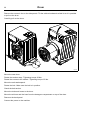
Washer extractor
W575S, W585S, W5105S, W5130S, W5180S,
W5250S, W5330S
Type W3...
Original instructions
438 9038-70/EN
2013.03.27
Contents
Contents
1 Symbols ............................................................................................................................... 5
2 Technical data ...................................................................................................................... 6
2.1 Drawing ........................................................................................................................ 6
2.1.1 W575S, W585S, W5105S, W5130S..................................................................... 6
2.1.2 W5180S ................................................................................................................ 7
2.1.3 W5250S, W5330S ................................................................................................ 8
2.2 Technical data............................................................................................................... 9
2.3 Connections.................................................................................................................. 9
2.4 Sound levels ................................................................................................................. 9
3 Machine presentation......................................................................................................... 10
4 Function check ....................................................................................................................11
5 Door and door lock............................................................................................................. 12
5.1 Door lock .................................................................................................................... 12
6 Motor and motor control ..................................................................................................... 16
6.1 Motor control unit........................................................................................................ 16
6.2 Replacement of motor ................................................................................................ 17
7 Heating............................................................................................................................... 19
7.1 Replacement of heating element................................................................................ 19
8 Drum .................................................................................................................................. 20
8.1 Replacement of drum ................................................................................................. 20
8.2 Replacement of the belt.............................................................................................. 23
8.2.1 Belt tension ......................................................................................................... 23
8.2.2 Adjusting the belt tension.................................................................................... 24
8.3 Replacing bearings..................................................................................................... 26
8.3.1 Remove the pulley .............................................................................................. 27
8.3.2 Demount the bearing .......................................................................................... 28
9 Drain................................................................................................................................... 37
9.1 Drain valve.................................................................................................................. 37
10 Detergent container.......................................................................................................... 40
10.1 Replacement of detergent container ........................................................................ 41
11 Control panel .................................................................................................................... 42
11.1 Control system.......................................................................................................... 42
11.1.1 Description ........................................................................................................ 42
11.1.2 Connections ...................................................................................................... 43
11.1.3 Replacement of control system CPU ................................................................ 44
11.2 Control knob ............................................................................................................. 49
11.2.1 Replacement of control knob ............................................................................ 49
11.3 USB connection ........................................................................................................ 51
12 I/O modules...................................................................................................................... 52
12.1 General..................................................................................................................... 52
12.2 Replacement of I/O module...................................................................................... 53
12.3 Functions for I/O-cards ............................................................................................. 56
12.3.1 External coin meter/Central payment (2A)........................................................ 56
12.3.2 Central payment (2B)........................................................................................ 57
12.3.3 Central payment (2C)........................................................................................ 58
12.3.4 Outputs for detergent signals and inputs for pause signals, "empty" signal
and price reduction (2D) .................................................................................... 59
Contents
12.3.5 Central booking/payment (2F) .......................................................................... 60
12.3.6 Machines with I/O module type 3...................................................................... 61
13 Troubleshooting................................................................................................................ 62
13.1 General..................................................................................................................... 62
13.2 Error code................................................................................................................. 63
13.3 Description of error codes and causes ..................................................................... 69
MAIN COMMON .......................................................................................................... 69
MAIN WASHER ........................................................................................................... 70
MAIN DRYER .............................................................................................................. 77
13.3.1 MAIN BARRIER ................................................................................................ 85
13.3.2 MAIN W&D........................................................................................................ 86
13.3.3 MAIN DRYER ................................................................................................... 87
DRUM MOTOR COMMON .......................................................................................... 89
DRUM MOTOR EWD .................................................................................................. 90
13.3.4 DRUM MOTOR KEB......................................................................................... 95
FAN MOTOR COMMON............................................................................................ 106
INTERNAL COM........................................................................................................ 107
INTERNAL COM. I/O TYPE 10.................................................................................. 109
INTERNAL COM. I/O TYPE 6.....................................................................................112
13.3.5 EXTERNAL COM. CMIS..................................................................................113
EXTERNAL COM. PAYMENT.....................................................................................114
EXTERNAL COM. CMIS.............................................................................................115
13.3.6 INTERNAL .......................................................................................................116
14 Maintenance....................................................................................................................117
14.1 Inspect the interior of the machine ..........................................................................117
The manufacturer reserves the right to make changes to design and component specifications.
Symbols
1 Symbols
Caution
Caution, hot surface
Read the instructions before using the machine
5
Technical data
6
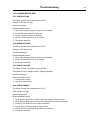
2 Technical data
2.1 Drawing
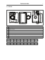
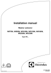
2.1.1 W575S, W585S, W5105S, W5130S
I
M
A
3
B
1
10
G
4
5
11
J
6
8
9
2
C
K
H
L
F
D
N
E
7
O
fig.7649A
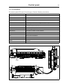
1
Operating panel
2
Door opening, W575S, W585S: ⌀ 310 mm, W5105S, W5130S: ⌀ 365 mm
3
Detergent container
4
Cold water
5
Hot water
6
Water re-use
7
Drain valve
8
Liquid detergent supply
9
Electrical connection
10
Steam connection
mm
A
B
C
D
E
F
G
H
W575S
660
1094
1131
355
686
835
80
1034
W585S
660
1157
1132
355
726
836
80
1035
W5105S
720
1187
1200
365
697
920
80
1119
W5130S
720
1326
1201
365
787
920
80
1119
I
J
K
L
M
N
O
W575S
217
124
1014
914
278
101
199
W585S
217
124
1015
915
278
103
199
W5105S
224
124
1099
999
278
105
212
W5130S
224
124
1099
999
278
103
212
mm
Technical data
7
2.1.2 W5180S
I
M
1
A
3
B
G
4
P
10
5
6
J
8
9
2
C
L
F
D
K
H
N
E
O
7
fig.7783
1
Operating panel
2
Door opening, W5180S
3
Detergent container
4
Cold water
5
Hot water
6
Water re-use
7
Drain valve
8
Liquid detergent supply
9
Electrical connection
10
Steam connection
mm
W5180S
mm
W5180S
A
B
C
D
E
F
G
H
751
1431
1344
435
875
1048
81
1249
I
J
K
L
M
N
O
P
297
132
1229
1129
278
104
231
217
Technical data
8
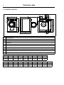
2.1.3 W5250S, W5330S
I
M
A
B
1
3
J
4
G
P
5
6
10
8
1
Q
2
C
L
F
D
K
H
N
E
7
O
fig.7650A
1
Operating panel
2
Door opening, W5250S, W5330S: ⌀ 435 mm
3
Detergent container
4
Cold water
5
Hot water
6
Water re-use
7
Drain valve
8
Liquid detergent supply
9
Electrical connection
10
Steam connection
mm
A
B
C
D
E
F
G
H
W5250S
830
1594
1425
470
949
1129
80
1328
W5330S
910
1679
1464
500
1034
1034
80
1367
I
J
K
L
M
N
O
P
Q
W5250S
327
233
1288
1203
278
100
264
162
287
W5330S
347
247
1327
1247
278
104
210
162
287
mm
Technical data
9
2.2 Technical data
W575S
W585S
W5105S
W5130S
W5180S
W5250S
W5330S
kg
129
135
145
175
228
287
330
litres
75
85
105
130
180
250
330
Drum diameter
mm
520
520
595
595
650
725
795
Drum speed during wash
rpm
49
49
49
49
44
44
42
Drum speed during
extraction
rpm
830
830
776
776
742
702
641
200
200
200
200
200
200
200
kW
5.4
5.4
5.4
7.5
13
18
23
kW
7.5
7.5
7.5
10
Weight, net
Drum volume
G-factor, max.
Heating: Electricity
kW
10
Heating: Steam
x
x
x
x
x
x
x
Heating: Hot water
x
x
x
x
x
x
x
Frequency of the dynamic
force
Hz
13.8
13.8
12.9
12.9
12.4
11.7
11.2
Floor load at max
extraction
kN
1.6 ± 2.4
1.7 ± 2.6
1.9 ± 3.0
2.3 ± 3.8
3.0 ± 4.8
3.8 ± 5.9
4.3 ± 6.9
W575S
W585S
W5105S
W5130S
W5180S
W5250S
W5330S
2.3 Connections
Water valves
DN
BSP
20
3/4”
20
3/4”
20
3/4”
20
3/4”
20
3/4”
20
3/4”
20
3/4”
Recommended water
pressure
kPa
200–600
200–600
200–600
200–600
200–600
200–600
200–600
Functioning limits for
water valve
kPa
50–1000
50–1000
50–1000
50–1000
50–1000
50–1000
50–1000
Capacity at 300 kPa
l/min
20
20
20
20
30
60
60
mm
75
75
75
75
75
75
75
Draining capacity
l/min
170
170
170
170
170
170
170
Steam valve connection
DN
BSP
15
1/2”
15
1/2”
15
1/2”
15
1/2”
15
1/2”
15
1/2”
15
1/2”
Recommended steam
pressure
kPa
300–600
300–600
300–600
300–600
300–600
300–600
300–600
Functioning limits for
steam valve
kPa
50–800
50–800
50–800
50–800
50–800
50–800
50–800
Drain valve
⌀ outer
2.4 Sound levels
The sound power level of the machine is determined by using ISO 3747:2012.
According to test code IEC 60704-2-4 the sound power level at extraction and during washing
are according to the table:
W575S
W585S
W5105S
W5130S
W5180S
W5250S
W5330S
Wash
dB(A)
64
64
63
63
70
67
68
Extraction
dB(A)
75
75
71
72
74
76
75
Machine presentation
10
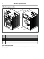
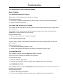
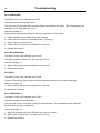
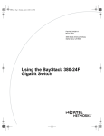
3 Machine presentation
7
6
5
1
4
2
3
8
fig.7749
①
1
Door
2
Motor
3
Heating unit
4
Drum
5
Detergent container
6
Control panel with Control system
7
I/O modules
8
Drain
After a repair has been made
Whenever a repair has been made, a function check must be performed before the machine can
be used again.
Function check
11
4 Function check
May only be carried out by qualified personnel.
A function check must be made when the installation is finished and before the machine can be
ready to be used.
Open the manual water valves.
Add detergent in the compartment for main wash and start a program.
• Check that the drum rotates normally and that there are no unusual noises.
• Check that there are no leaks in water supply/drain connections.
• Check that water passes through the detergent container.
• Check that the door cannot be opened during a program.
Ready to use
If all tests are OK the machine is now ready to be used.
If some of the tests failed, or deficiencies or errors are detected, please contact your local service
organisation or dealer.
12
Door and door lock
5 Door and door lock
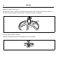
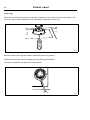
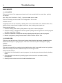
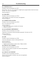
5.1 Door lock
The door lock consists of:
• An actuator that locks the door lock and also has one built-in micro switch. The actuator is
bi-stable, i.e., it has two stable positions: locked door and unlocked door. The actuator must
receive a pulse to lock and unlock the door lock.
• A micro switch that is closed when the door is closed.
• An emergency opening button that can be used to open the door lock in an emergency .
②
fig.7750
Door and door lock
13
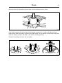
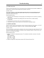
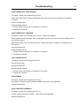
Replacement of door lock
Disconnect the power to the machine.
Demount the front panel.
③
fig.7751
14
Door and door lock
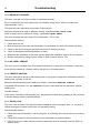
Demount the door.
Demount the trim panel.
Disconnect the door lock cables and demount the door lock.
④
fig.7753
Mount the new door lock and connect the cables.
Mount the trim panel.
Mount the door and the front panel.
Door and door lock
15
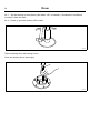
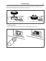
Emergency opening of door lock
The door can be opened by pressing the emergency opening button.
To access the emergency opening button, remove the front panel. The emergency opening button
can be reached between the left side panel and the trim panel. If not accessible, remove also
the trim panel.
⑤
fig.7752
16
Motor and motor control
6 Motor and motor control
Take care when measuring the motor control system since all components have a potential difference of
approximately 300V in relation to protective earth and neutral.The components will contain dangerous
voltages when the green LED on the motor control board is on. The motor control system will remain live for
30-60 seconds after cutting the power to the machine and the motor has stopped running.
6.1 Motor control unit
The motor control unit communicates with the control system via a serial (input/output) interface.
With the aid of the motor control unit the control system can control not only the speed of the motor
at any given point, but also the acceleration or deceleration rate at which the motor is to achieve the
speed required. The motor control unit constantly feeds information on current status (both normal
status and on any abnormalities arising) back to the control system.
The motor control unit can also supply data on the different torque and effect of the motor at
constant speed when accelerating and deceleration. These data are used both for calculating the
weight of the load and for detecting any unbalance.
The voltage on the motor control circuit has a potential difference of approx. 300 V in relation to incoming
neutral and earth. Because of this, be careful when measuring. Use unearthed oscilloscopes. If the motor
control unit has a green LED, this will remain lit for as long as there are hazardous voltages present in
components.
Motor and motor control
17
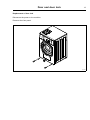
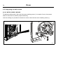
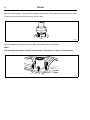
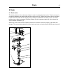
6.2 Replacement of motor
Disconnect the power to the machine.
Demount the rear panel.
Remove the belt.
Demount the cover panel to the motor cable.
Disconnect the motor cable and unscrew the earth screw.
⑥
fig.7765
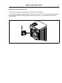
Demount the motor.
⑦
fig.7766
18
Motor and motor control
Mount the new motor.
Connect the motor cable and refit the earth screw.
Mount the cover panel to the motor cable.
Fasten the belt. Make sure the belt is in position.
Check the belt tension.
Mount the rear panel.
Heating
19
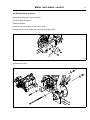
7 Heating
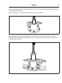
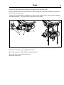
7.1 Replacement of heating element
Disconnect the power to the machine.
Demount the front panel.
Remove the cover to the heating elements.
Disconnect the connectors to the heating elements.
⑧
fig.7767
Loosen the bolt to the heating element and gently push on the middle of the heating element
to release the flange.
Remove the heating element and insert the new heating element.
⑨
fig.7756
Push on the middle of the heating element to get the flange in position.
Fasten the bolt. Use tightening torque 6 Nm.
Reconnect the connectors to the heating element, use the electric schematic supplied with the
machine.
20
Drum
8 Drum
8.1 Replacement of drum
Disconnect the power to the machine.
Demount the back panel.
Demount the drain and hoses to the drum. Drain and type of hoses are depending on machine
model, (for more information refer to the spare parts list).
Demount the air hose and the hose from the detergent compartment on top of the drum.
Remove the belt.
Demount the anti-rotationpanel.
⑩
fig.7784
Drum
21
Unscrew the screws to the tension strap.
⑪
fig.7785
22
Drum
Remove the screws in the on the side panels. Tilt the cabinet backwards a little bit so it is possible
to pull out the drum.
Carefully pull out the drum.
⑫
6x
fig.7786
Mount the new drum.
Fasten the tension strap. Tightening torque 26 Nm.
Fasten the screws to the cabinet. Tightening torque 6.5 Nm.
Mount the anti-rotationpanel.
Fasten the belt. Make sure the belt is in position.
Check the belt tension.
Mount the drain and hoses to the drum.
Mount the air hose and the hose from the detergent compartment on top of the drum.
Remount the back panel.
Connect the power to the machine.
Drum
23
8.2 Replacement of the belt
Disconnect the power to the machine.
Demount the rear panel.
Remove the belt (A) and put the new belt in position.
The belt tension should be according to the table, adjust if necessary.
⑬
A
B, C
A
fig.7769A
Remount the rear panel.
Connect the power to the machine.
8.2.1 Belt tension
The belt tension should be according to the table.
Model
A = Force (N)
B = Post tensioning (mm)
C = New belt (mm)
W575S
35
8
6
W585S
35
9
8
W5105S
40
8
7
W5130S
40
8
7
W5180S
60
9
7
W5250S
68
8
7
W5330S
45
8
6
24
Drum
8.2.2 Adjusting the belt tension
8.2.2.1 W575S, W585S, W5105S
To adjust the belt tension, first undo the motor retaining screw (1) a couple of turns, then press
down on the motor to achieve proper tensioning.
Lock the locking nut (2) when the tension is correct, then lock the motor retaining screw (1).
⑭
2
1
fig.7769
Drum
25
8.2.2.2 W5130S, W5180S, W5250S, W5330S
To adjust the belt tension, first undo the motor retaining screw (1) a couple of turns to increase or
decrease the belt tension.
• Increase the belt tension by turning the screw (2) clockwise.
• Decrease the belt tension by turning the screw (2) counter clockwise.
Lock the locking nut (2) when the tension is correct, then lock the motor retaining screw (1).
⑮
fig.7790
Drum
26
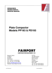
8.3 Replacing bearings
Complete tool kit, part No: 472 9913-60
⑯
7
8
9
10
1
2
6
5
4
3
11
13
12
14
15
fig.7038
1. 432 1723-01: Drift for gaskets (W365/465/565-3105/4105/5105H/N/M/S,
W3130/4130/5130N/M/S, EX618/718, 625/725, E/W/SU630/730)
2. 432 1723-02: Drift for gaskets (W3130/4130/5130-3300/4300/5300H, W3180/4180/51803330/4330/5330N/M/S, EX630/730-670/777, E/W/SU640/745-675/777)
3. 432 1716-01: Spacer (W365/465/565-385/485/585H/N/M/S, EX618/718, E/W/SU620/720)
4. 432 1716-02: Spacer (W3105/4105/5105H/N/M/S, W3130/4130/5130N/M/S, EX625/725,
E/W/SU630/730)
5. 432 1716-03: Spacer (W3130/4130/5130H, W3180/4180/5180N/M/S, EX630/730, E/W/SU640)
6. 432 1716-04: Spacer (W3180/4180/5180-3300/4300/5300H, W3250/4250/52503330/4330/5330N/M/S, EX640/745-670/777, E/W/SU655/762-675/777)
7. 432 1719-01: Drift, large bearing (W365/465/565-385/485/585H/N/M/S, EX618/718,
E/W/SU620/720)
8. 432 1719-02: Drift, large bearing (W3105/4105/5105H/N/M/S, W3130/4130/5130N/M/S,
EX625/725, E/W/SU630/730)
9. 432 1719-03: Drift, large bearing (W3130/4130/5130H, W3180/4180/5180N/M/S, EX630/730,
E/W/SU640/745)
10. 432 1719-04: Drift, large bearing (W3240/4240/5240-3300/4300/5300H, W3250/4250/52503330/4330/5330N/M/S, EX655/762-670/777, E/W/SU655/762-675/777)
11. 432 1730-01: Presser (W365/465/565-3105/4105/5105H/N/M/S, EX618/718-625/725,
E/W/SU620/720)
12. 432 1730-02: Presser (W3130/4130/5130-3300/4300/5300H, W3180/4180/51803330/4330/5330N/M/S, EX630/730-670/777, E/W/SU640/745-675/777)
13. 432 1722-01: Washer
14. 432 1727-01: Extender
15. 432 1729-01: Puller block, large bearing
Start by removing the pulley:
Drum
27
8.3.1 Remove the pulley
Remove the C-clamp from the drum shaft.
Mount the puller with puller drags on shaft and pulley.
⑰
fig.7033
Warm the pulley around the shaft so that the aluminium expands slightly. Then it is easier to
pull off the pulley.
⑱
fig.7034
Pull off the pulley.
Drum
28
8.3.2 Demount the bearing
Remove wedge from shaft.
Measure the distance (A) between bearing and end of shaft.
B = Shaft
C = Bearing
⑲
B
A
C
fig.6999
Loosen the bolts in the bearing house.
⑳
fig.7039
Drum
29
Mount two bolts in threaded holes and press until the bearing house is loose.
21
fig.7040
If the front bearing is still on the shaft, use the puller to remove it. In order to be able to put the
puller blocks under the bearing, push the rear gable a little. Do not attempt to remove the rear gable
when the bearing is still on the shaft. It will result in a damaged lining.
Remove the sealings and then the rear gable.
22
fig.7041A
30
Drum
Alt. 1. Tap the bushing in three places (with about 120° in between). Sometimes it is sufficient
to loosen it from the shaft.
Alt. 2. Chisel or grind the bushing off the shaft.
23
fig.7044
Tap the bearings from the bearing house.
Clean the bearing house thoroughly.
24
fig.7045
Drum
31
Bearing kit
fig.7046
25
472 9913-12: W365H, W375H/N, W385N/M, W465H, W475H/N, W485N/M, EX618, E/W620
472 9913-13: W3105H/N/M, W3130N/M, W4105H/N/M, W4130N/M, EX625, E/W630
472 9913-15: W3250N/M, W4250N/M, E/W655
472 9913-14: W3180N/M, W4180N/M, E/W640
472 9913-16: W3330N, W4330N, E/W675
472 9913-16: W3330N/M, W4330N/M
Tap the bearing gently into the housing with drift and washer.
26
fig.7047A
Drum
32
Turn the housing around and gently tap the rear bearing into the housing using the presser.
27
fig.7049A
Mount the sealing rings.
A = Bearing housing
B = Sealing rings
28
A
B
fig.7000
Drum
33
Put some grease on the inside of the bearing housing. Then it is easier to mount the sealing rings.
29
fig.7051
Fill the first sealing with grease.
Place the sealing on the drift with the opening up. Tap carefully it down in the bearing housing.
Push it down until it stops.
30
fig.7052A
Fill the second sealing with Amblygon grease. Place the spacer and sealing on the drift. Press
down the drift to the bottom.
31
fig.7054A
34
Drum
Mount the third sealing. The lip shall lay against the housing. Don't push too far as the lip can break.
Thread the shaft end with M10 and min 20 mm deep.
32
fig.7057
Mount the bearing housing to the rear gable and tighten the bolt crosswise.
Note!
The marking (up) shall be pointing upwards when rear gable is in place on the machine.
33
fig.7058
Drum
35
Mount the rear gable over the drum shaft. Be sure to put it on horizontally so that the sealings don't
get damaged on the shaft.
Mount the adaptor on the shaft end and thread it down to the bottom.
34
fig.7059
Mount presser, washer, nut and puller bolt. Press down the rear gable until stop. Check the
measure between the shaft end and bearing race. This measure was taken before removing the
rear gable from the shaft.
35
fig.7060
36
Drum
Mount the wedge on the shaft.
Mount pulley, sleeve, washer, nut and puller bolt onto the shaft. Thread the bolt to the adaptor on
the shaft. Press the pulley onto the shaft. It is easier if the pulley is heated.
36
fig.7061
Lock the pulley with the C-clamp.
Replace the gasket around the circumference of the rear gable.
37
fig.7062
Drain
37
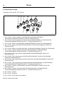
9 Drain
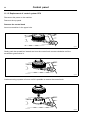
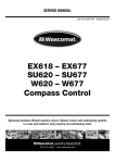
9.1 Drain valve
The water pressure in the cold water intake is used for closing the drain valve. There is a hose (1)
connected between the water intake and the control valve (2). When the control valve is activated
it opens and lets water into the supply line (3) which is connected to the drain valve. The water
presses up a rubber membrane (4) and a plunger (5) with a pressure plate (6) which closes the
valve’s rubber membrane (7).
When the control valve shuts off water pressure to the drain valve the springs (8) pull back the
plunger. The return water passes the control valve and runs out into the drain via the return hose (9).
38
1
2
9
3
7
6
8
5
4
fig.7757
38
Drain
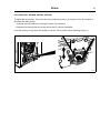
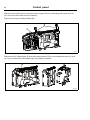
Replacement of drain valve
Disconnect the power to the machine.
Demount the front panel.
Remove the cover to the heating elements.
39
fig.7751A
Drain
39
Loosen the hose clamps and demount the hoses (A) from the drain valve.
Remove the hose from the valve’s nipple for water supply (B). (Press the orange ring and pull out
the hose at the same time).
Loosen and unscrew the four retaining nuts of the valve a couple of turns (use a socket, extender
and ratchet wrench). Turn the valve and unlock it from the bolts.
40
B
A
A
fig.7761
Mount the new drain valve and tighten the bolts.
Mount the hoses (A and B). Tighten the hose clamps.
Mount the cover to the heating elements.
Mount the front panel.
40
Detergent container
10 Detergent container
Water connections into the detergent container are fitted with dispensers which mix the detergent
thoroughly with water and flush the compartments clean. From the bottom of the detergent
container the water is flushed down into the drum.
41
Detergent container
41
10.1 Replacement of detergent container
Demount the top panel.
Loosen the hose clamps and demount the hoses to the detergent container.
Remove the detergent container and mount the new one. Connect the hoses and fasten the hose
clamps.
42
fig.7758
42
Control panel
11 Control panel
11.1 Control system
11.1.1 Description
The control system CPU is electronic and comprises a circuit board containing microprocessor,
program memory, serial interface to the motor control, I/O-boards etc.
The control system CPU receives its power from a separate power supply unit.
43
fig.7763
The control system receives information about inputs like temperature sensor, level sensor, door
status and activates outputs like water valves, drain and heat control.
Control panel
43
11.1.2 Connections
The control system CPU and I/O module type 10 has the following connections:
Board connector
Function
M-COM
Communication, motor control
D-BUS
Databus
D-BUS
Databus
TACHO
Tachometer
COIN
Coin meter (coin 1, coin 2, blocking) price programming
INP 1
Input 1, stop button
INP 2
Free program (key switch) / Input 2
RS 232
Serial communication
ENC
Control knob (pulses)
USB TYPE B
Connection for software / service download
PIN CONNECTOR
Panel sign connector
LEVEL
Level controls
DO
Door out, door lock solenoid
OUTP
Output
DOOR IN
Door lock micro switches
P-BUS
Power bus
TEMP
Temp sensor
44
ENC
RS232
INP2
INP1
COIN
TACHO
D-BUS
D-BUS
M-COM
IN
USB Type B
fig.W00284
44
Control panel
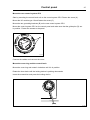
11.1.3 Replacement of control system CPU
Disconnect the power to the machine.
Demount the top panel.
Demount the control knob
Insert a screwdriver in the upper hole.
45
fig.7491
Gently push the screwdriver inwards and turn the control knob counter-clockwise until the
screwdriver goes further in.
46
fig.7492
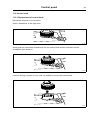
Continue turning a quarter of a turn until it is possible to remove the control knob.
47
fig.7493
Control panel
45
Demount the cover ring
When the control knob is removed, insert the screwdriver in the lower hole and press gently. Turn
the cover ring counter-clockwise until it is possible to remove the cover ring.
48
fig.7490
Demount the control system CPU
Demount the cover and disconnect the cables.
Loosen the screws holding the control system CPU onto the panel and demount the control system
CPU.
49
fig.7764
Control panel
46
Demount the control knob unit from the control system CPU by unscrewing the screw (A) a bit
(4–5 mm) until the control knob unit loosens.
Demount the two grounding brackets (B).
50
B
A
fig.7640
Demount the I/O module type 10 from the control system CPU by unscrewing the screw (C) a bit
(4–5 mm). Remove the I/O module type 10 by lifting it upwards.
51
C
fig.7640A
Control panel
47
Mount the new control system CPU
Start by mounting the control knob unit on the control system CPU. Fasten the screw (A).
Mount the I/O module type 10 and fasten the screw (C).
Mount the two grounding brackets (B) on the new control system CPU.
Mount the control system CPU on the control panel and make sure that the guide pins (D) are
in position. Fasten the screws to the panel.
52
D
fig.7511
Connect the cables and remount the cover.
Mount the cover ring and the control knob
Mount the cover ring and rotate it clockwise until it is in position.
Rotate the inner knob until the locking device is pointing downwards.
Insert the screwdriver and press the locking device.
53
fig.7494
48
Control panel
Mount the control knob on the inner knob. Continue to press with the screwdriver and turn the
control knob clockwise until it stops when it is in position.
54
fig.7495A
Control panel
49
11.2 Control knob
11.2.1 Replacement of control knob
Disconnect the power to the machine.
Insert a screwdriver in the upper hole.
55
fig.7491
Gently push the screwdriver inwards and turn the control knob counter-clockwise until the
screwdriver goes further in.
56
fig.7492
Continue turning a quarter of a turn until it is possible to remove the control knob.
57
fig.7493
50
Control panel
Cover ring
When the control knob is removed, insert the screwdriver in the lower hole and press gently. Turn
the cover ring counter-clockwise until it is possible to remove the cover ring.
58
fig.7490
Mount the new cover ring and rotate it clockwise until it is in position.
Rotate the inner knob until the locking device is pointing downwards.
Insert the screwdriver and press the locking device.
59
fig.7494
Control panel
51
Mount the new control knob on the inner knob. Continue to press with the screwdriver and turn
the control knob clockwise until it stops when it is in position.
60
fig.7495A
11.3 USB connection
To open the USB connection; use a screwdriver to carefully press and open the lid.
61
fig.W00416
52
I/O modules
12 I/O modules
12.1 General
The machine can be equipped with either two or more I/O modules:
• I/O module type 1, 11 or 3 is always installed in the machine at delivery. It controls internal
machine functions and outputs to heating, water valves, drain etc.
• I/O module type 10 is always installed in the machine at delivery. It controls the door lock
functions.
• I/O module type 2 is installed as an option. It controls the external functions like detergent dosing
systems and inputs from payment and booking systems etc.
The functionality of I/O module inputs and outputs is depending on the parameter software
downloaded to the machine’s control system. The function options for the I/O modules are indicated
by a letter in the program designation for each module.
Location
The parameter software installed in the machine’s control system on delivery is specified at the front
and back of the machine.
Using this article number, you can find the program designation and thereby identify I/O module
function options on the web.
62
fig.W00297
I/O modules
53
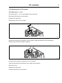
12.2 Replacement of I/O module
I/O module type 1, 11 or 3
I/O module type 1, 11 or 3 are installed in the same way.
Disconnect the power to the machine.
Demount the top panel.
Remove the cover on the module.
63
fig.7798
Remove the electrical connections on the module. (Note the position of the connections).
Remove the module by pulling it upwards.
64
fig.7799
Insert the new module and make sure it is in position.
Connect the electrical connections in the same way as before.
Mount the cover.
Remount the top panel.
Connect the power to the machine.
54
I/O modules
I/O module type 2
Disconnect the power to the machine.
Demount the cover panel at the back of the machine.
65
fig.7797
Remove the electrical connections on the module. (Note the position of the connections).
Remove the module by lifting it towards you and up a bit and then pushing it to the left.
66
fig.7800
Insert the new module and make sure it is in position.
Connect the electrical connections in the same way as before.
Remount the cover panel.
Connect the power to the machine.
I/O modules
55
I/O module type 10
Disconnect the power to the machine.
Demount the top panel.
Remove the cover to the control system and I/O module type 10.
Remove the electrical connections on the module. (Note the position of the connections).
Loosen the screw (A) a bit and remove the I/O module by lifting it upwards.
67
A
fig.7801
Insert the new module and make sure it is in position.
Connect the electrical connections in the same way as before.
Fasten the screw (A) and remount the cover.
Remount the top panel.
Connect the power to the machine.
56
I/O modules
12.3 Functions for I/O-cards
The electrical schematic can be one of the following:
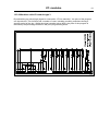
12.3.1 External coin meter/Central payment (2A)
The signal received from external coin meters must be a pulse between 300–3000 ms (500 ms is
recommended) with a minimum pause of 300 ms (500 ms is recommended) between two pulses.
68
fig.6606A
I/O modules
57
12.3.2 Central payment (2B)
To start the machine from a central payment system, the payment system must transmit a start
pulse to the machine. The start pulse can be either 230V or 24V. In order to receive a feedback
signal once the machine has started, 230V or 24V must be connected to connection 19. The
feedback signal on connection 18 remains active (high) during the entire program.
69
fig.6316A
58
I/O modules
12.3.3 Central payment (2C)
The central payment or booking system shall transmit an active (high) signal to the machine once
permission has been granted to start the machine. The signal must remain active (high) until the
machine starts. A feedback signal will be present on connection 18 and remain active (high) whilst
the machine door is closed but the program has not started. The feedback signal is powered
by 230V or 24V from connection 19.
70
fig.6313A
I/O modules
59
12.3.4 Outputs for detergent signals and inputs for pause signals, "empty" signal
and price reduction (2D)
The figure shows standard function addressing for machines with the coin program package.
By maintaining an active (high) signal on connection 5 ("Price red"), the price of the program can
be reduced. This function has a number of uses, including providing reductions during a specific
period of the day. Whilst the signal remains active (high), the price of the program is reduced by the
percentage entered in the price programming menu.
71
fig.6314A
I/O modules
60
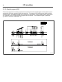
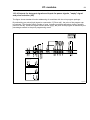
12.3.5 Central booking/payment (2F)
The central payment or booking system shall provide an active (high) signal to the machine once
permission has been granted to start the machine. The signal must remain active (high) until the
machine starts. A feedback signal will be present on connection 18 and remain active (high) whilst
the program is running. The feedback signal is powered by 230V from connection 19 or external 24V.
72
Function I/O:s
F
3
5
6
1
2
1
2
5
RE101
Output 6 NO
Output 6 NC
RE102
RE103
RE104
4
Output 5
RE105
3
Output 4
Output 3
Output 2
Output 1
Input 4
Input 3
4
6
Con 107
1
2
Con 115
2
Con 109
1
Input 2
Input 1
RE106
Con 110
Con 108
2
Com.
Com.
Con 111
1
+5V
2
PTD5
Type of I/O card
3
Program run NC
Program run NO
Liquid det. sign 5
Liquid det. sign 4
Liquid det. sign 3
Liquid det. sign 2
Liquid det. sign 1
Common
Power for outputs
Common outputs
Temporary pause
Liq. det. empty
Heating pause
Blocking of start
Com. 24V(-)
Com. 100 -240V
Line
Central booking / payment
Start permitted
230V
Com. 24V(-)
Neutral
Inp
Central booking / payment
Start permitted
24V
0V
+24V
M1
Start permitted
S1
M1
Central payment
S1
Status machine
fig.6944A
I/O modules
61
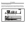
12.3.6 Machines with I/O module type 3
By maintaining an active (high) signal on connection 3 "Price reduction”, the price of the program
can be reduced. This function has a number of uses, including providing reductions during a
specific period of the day. Whilst the signal remains active (high), the price of the program is
reduced by the percentage entered in the price programming menu.
2 :C o m 1 0 0 -2 4 0 V A C
3 :In p u t P ric e re d u c tio n
1 :C o m 5 -2 4 V A C /D C
73
2
3
1
2
P-BUS
3
4
1
2
P-BUS
3
4
1
P U M P
D R A IN
CPU
1
D R A IN
1
H O T
1
C O LD
1
2
3
fig.6636
62
Troubleshooting
13 Troubleshooting
13.1 General
The troubleshooting section is used to trace errors in the machine to a defective component or unit.
There is a memory in the control system that will save the selected program for 10 minutes in the
case of power failure. The machine will restart in pause mode if the power is turned on again within
this time. For very short power failure (less than 10 seconds) the machine will restart automatically.
Safety regulations
Troubleshooting may only be carried out by authorised personnel.
Take care during all work on the machine while the power is on.
Take care when measuring the motor control system since all components have a potential difference of
approximately 300V in relation to protective earth and neutral.The components will contain dangerous
voltages when the green LED on the motor control board is on. The motor control system will remain live for
30-60 seconds after cutting the power to the machine and the motor has stopped running.
Measurements
For information on measuring points, components and voltages, please refer to the electric
schematic supplied with the machine.
Troubleshooting
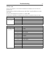
13.2 Error code
An error in the program or in the machine is indicated on the display by an error code and a
descriptive text.
The error codes are divided into different groups called “Major” comprising different error codes
called “Minor”.
The errors will be displayed as for example 11:2 DOOR OPEN.
The following is a description of all Major groups followed by a description of each error code.
Error code
Text
Major
Minor
10
1
INTERNAL ERROR CPU TACHO
MAIN COMMON
11
REAL TIME CLOCK OUT OF ORDER
13
INITIALIZING FAILED
15
MACHINE STOP
16
EMERGENCY STOP
Error code
Text
Major
Minor
11
1
NO WATER
MAIN WASHER
2
DOOR OPEN
3
DOOR LOCK FAIL
4
WATER LOW TEMP
5
WATER HIGH TEMP
6
WATER IN MACHINE
8
NO HEATING
9
DRUM OVERFILLED
10
DRUM NOT DRAINED
12
NO LEVEL SENSOR
16
TIMEOUT HEATING
17
DOOR LOCK
27
LEVEL OFFSET
28
WATER LEVEL HIGH DLCU LEVEL LOW
29
WATER LEVEL LOW DLCU LEVEL HIGH
126
CO2 BOTTLE EMPTY
127
DRAWER OUT
63
Troubleshooting
64
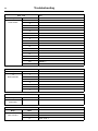
Error code
Text
Major
Minor
12
1
O.H. THERMOSTAT - INLET AIR
MAIN DRYER
2
O.H. THERMOSTAT - OUTLET AIR
3
INLET AIR SENSOR OPEN
4
INLET AIR SENSOR SHORT CIRCUITED
5
OUTLET AIR SENSOR OPEN
6
OUTLET AIR SENSOR SHORT CIRCUITED
8
CONDENSE WATER CONTAINER IS FULL
9
HEAT PUMP LOW PRESSURE
10
HEAT PUMP HIGH PRESSURE
11
DRYING ERROR WITH RMC PROGRAM
12
DRYING ERROR WITH AUTOSTOP PROGRAM
13
DRYING ERROR WITH TIME PROGRAM
14
GAS ERROR PRESS GAS REST BUTTON
15
NO VACUUM
16
VACUUM SWITCH SHORTED
253
JUMPER 1
254
JUMPER 2
255
JUMPER 3
Error code
Text
Major
Minor
13
1
DRUM POSITIONING TIMED OUT
MAIN BARRIER
2
DRUM UNLOCKING
3
INNER DOOR OPENING
4
INNER DOOR JACK POSITION
5
DOOR UNLOCKING
6
DRUM LOCK POSITION SWITCH
7
DRUM NOT ROTATING
Error code
Text
Major
Minor
14
1
EXTRACTION FAILED DRYING ABORTED
MAIN W&D
Error code
Text
Major
Minor
15
2
DOOR OPEN 2
MAIN POCKET
3
DOOR LOCK FAIL 2
17
DOOR LOCK 2
Troubleshooting
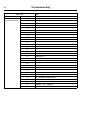
Error code
Text
Major
Minor
20
1
O.H. DRUM MOTOR
DRUM MOTOR
COMMON
2
NO MOTOR COMMUNINCATION
3
LOST MOTOR COMMUNICATION
Error code
Text
Major
Minor
21
1
HEATSINK TOO HOT
DRUM MOTOR EWD
2
MOTOR TOO HOT
3
NO INTERLOCK
4
NO COMMUNICATION
5
MOTOR SHORT CIRCUIT
6
INTERLOCK HARDWARE
7
LOW DC VOLTAGE
8
HIGH DC VOLTAGE
12
NO PARAMET. SET IN MCU
13
UNBALANCE
15
MOTOR NOT FOLLOW
65
Troubleshooting
66
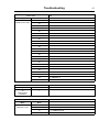
Error code
Text
Major
Minor
22
1
OVERVOLTAGE
DRUM MOTOR KEB
2
UNDERVOLTAGE
3
PHASE FAILURE
4
OVERCURRENT
6
OVERHEAT INTERNAL
7
NO OVERHEAT INTERNAL
8
OVERHEAT POWER MODULE
9
DRIVE OVERHEAT
11
NO DRIVE OVERHEAT
12
POWER UNIT
13
POWER UNIT NOT READY
14
POWER UNIT INVALID
15
LOAD SHUNT FAULT
16
OVERLOAD
17
NO OVERLOAD
18
BUS
19
OVERLOAD 2
20
NO OVERLOAD 2
21
EEPROM DEFECTIVE
22
POWER UNIT COMMUN.
23
BUS SYNCHRON.
30
MOTOR PROTECTION
31
EXTERNAL FAULT
32
ENCODER 1
33
POWER FACTOR CONTROL
36
NO OVERHEAT POWER MODULE
39
SET
46
PROTECT. ROT. FORWARD
47
PROTECT. ROT. REVERSE
49
POWER UNIT CODE INVALID
Troubleshooting
Error code
Text
Major
Minor
22
50
POWER UNIT CHANGED
DRUM MOTOR KEB
51
DRIVER RELAY
52
HYBRID
54
COUNTER OVERRUN 1
55
COUNTER OVERRUN 2
56
BRAKE
57
INITIALISATION MFC
58
OVER SPEED
87
OVERHEAT INT.
88
NO OVERHEAT POWER MODULE
89
OVERHEAT POWER MODULE
90
EXTERNAL FAULT
91
NO DRIVE OVERHEAT
92
NO OVERHEAT INT.
93
BUS
94
PROTECT. ROT. FORWARD
95
PROTECT. ROT. REVERSE
96
DRIVE OVERHEAT
97
MOTOR PROTECTION
98
NO OVERLOAD
99
OVERLOAD 1
100
OVERLOAD 2
101
NO OVERLOAD 2
102
SET
Error code
Text
Major
Minor
30
1
O.H. FAN MOTOR
FAN MOTOR
COMMON
Error code
Text
Major
Minor
40
1–10
I/O INTERLOCK Axxx
INTERNAL COM.
11–20
I/O COMMUNICATION Axxx
21
I/O COMMUNICATION
22
I/O BOARD MISMATCH
67
Troubleshooting
68
Error code
Text
Major
Minor
41
1
CHARGE CIRCUIT
INTERNAL COM.
I/O TYPE 10
2
SET SIGNAL, NO TACHO. WAIT 5 MINUTES
3
ACTUATOR CIRCUIT
21
CHARGE CIRCUIT
22
SET SIGNAL, NO TACHO. WAIT 5 MINUTES
23
ACTUATOR CIRCUIT
Error code
Text
Major
Minor
42
1
INTERNAL ERROR
INTERNAL COM.
I/O TYPE 6
2
POSITION TEST
3
EXTRACT TEST
Error code
Text
Major
Minor
50
18
START NOT ALLOWED
EXTERNAL COM.
20
OUT OF OPERATION
Error code
Text
Major
Minor
51
22
NO CBT COMMUNICATION
EXTERNAL COM.
PAYMENT
Error code
Text
Major
Minor
52
1
CMIS COMMUNICATION ERROR
EXTERNAL COM. MIS
2
DMIS COMMUNICATION ERROR
Error code
Text
Major
Minor
60
5
FATAL ERROR INVALID RUNNING MODE
INTERNAL
11
FATAL ERROR EXTERNAL FLASH WRITE
17
FATAL ERROR INVALID OPTION
18
FATAL ERROR INVALID MODULE
28
FATAL ERROR INVALID COIN INPUT
29
FATAL ERROR INVALID FONT
Troubleshooting
69
13.3 Description of error codes and causes
MAIN COMMON
10:1 INTERNAL ERROR CPU TACHO
Tacho input on CPU delivers values that is out of range.
Recommended actions:
1. Run motor on highest possible speed in service mode. Check input value for RPM speed.
2. Replace defective component.
10:11 REAL TIME CLOCK OUT OF ORDER
The real time clock is used by the control system for delayed start, measuring time, power failure,
error codes, etc.
Upon power on, the communication with the internal real time clock in the control system is
established. In case this fails, this error occurs
Recommended actions:
1. Power off the machine for 1 minute and try again.
10:13 INITIALIZATION FAILED
The error code is shown if the hardware initialization has failed to initialize within 15 seconds
after power on.
Recommended actions:
1. Press the control knob/start button to retry.
2. Upload a new software that matches the machine configuration and try again.
10:13 MACHINE STOP
This message is shown if input for MACHINE STOP is activated.
This is not an error code but is handled in the same way.
Recommended actions:
1. Reset the Machine Stop Button.
2. Press the control knob to confirm machine stop. Machine will revert to Idle mode.
10:13 EMERGENCY STOP
This message is shown if input for EMERGENCY STOP is activated. This is not an error code but is
handled in the same way.
Recommended actions:
1. Reset the Emergency Stop Button.
2. Press the control knob to confirm emergency stop. Machine will revert to Idle mode.
70
Troubleshooting
MAIN WASHER
11:1 NO WATER
This error is shown if the programmed water level is not reached within a certain time, typically
10 minutes.
Max. filling time is defined in Config. 1 parameter MAX FILL TIME.
This error message can be turned off in Configuration - Error code.
Possible causes:
Long filling times can be caused by a leaking drain valve, blocked filler valve, defective filler valve,
defective valve control board, clogged level sensor hose, leaking level system, etc.
Recommended actions:
1. Check for leaking drain valve by filling water to high level in service program.
2. Check for leaking or clogged level sensor system by filling water to high level in service program
and then actual level in inputs.
3. Check for malfunction or block filler valve by activating input by input in service program.
4. Monitor a program by using Process viewer in ELS Common Service Tool.
11:2 DOOR OPEN
This error code will be shown if the control system detect that the input DOOR CLOSED has been
deactivated during an on-going program. This error code can only occur during an on-going
program.
Possible causes:
This can be caused by for example a bad or defective door lock, loose cable to door lock, problem
with door lock edge connection, defective input on I/O unit type 10 etc.
Recommended actions:
1. Check door lock functionality in service program, but activating door lock and then by checking
inputs.
2. Check electrical connections by reading inputs at the same time as cables carefully
moved/pulled.
3. Carefully knock on the door lock to locate intermittent errors.
Troubleshooting
71
11:3 DOOR LOCK FAIL
This error code will be shown if the control system have not detected the input DOOR LOCKED to be
active within a certain time after program start, typically 3 seconds.
Possible causes:
This can be caused by a mechanical problem preventing door lock to lock, defective door lock,
loose cable connection to door lock, broken cables to door lock or mechanical problem with
emergency opening of the door.
Recommended actions:
1. Check door lock functionality in service program, but activating door lock and then by checking
check inputs.
2. Check electrical connections by reading inputs at the same time as cables carefully
moved/pulled.
3. Carefully knock on the door lock unit to locate intermittent errors.
4. Check DLCU status in service mode for more information on possible causes.
11:4 WATER LOW TEMP
This error code is shown if the temperature sensor indicates temperature below approx. -9°C/15°F
Minimum allowed temperature is defined in Config. 2 parameter MIN PROG TEMP.
Possible causes:
This low temperature means that the resistance in the sensor is higher than approximately 23.7 kΩ.
This can be caused if the machine for example has been standing outdoors, an open circuit in the
sensor or in the cable to the sensor.
Recommended actions:
1. Measure resistance in temperature sensor. The resistance should be as shown in the table
below:
Temp - Resistance
15°C / 59°F - 7.6 kΩ
20°C / 68°F - 6.0 kΩ
25°C / 77°F - 4.8 kΩ
2. Monitor a program by using Process viewer in ELS Common Service Tool.
Troubleshooting
72
11:5 WATER HIGH TEMP
This error code is shown if the temperature around the temperature sensor exceeds + 98°C/208°F
Maximum allowed temperature is defined in Config. 2 parameter MAX PROG TEMP.
Possible causes:
Such high temperature means that the resistance in the sensor is lower than approximately 350 Ω.
This can be caused by for example a short circuit in the sensor, break in the cable to the sensor, etc.
Recommended actions:
1. Measure resistance in temperature sensor. The resistance should be as shown in the table
below:
Temp - Resistance
15°C / 59°F - 7.6 kΩ
20°C / 68°F - 6.0 kΩ
25°C / 77°F - 4.8 kΩ
Monitor a program by using Process viewer in ELS Common Service Tool to detect intermittent
errors.
11:6 WATER IN MACHINE
This error code will only appear at program end.
Error is activated if the level system has not indicated “empty drum” within a certain time, typically
3 minutes.
This error code can also arise if the program is rapid advanced to the end, or if program is aborted.
Maximum allowed drain time can be changed in Config. 2 parameter MAX DRAIN TIME.
Level for empty drum is defined in Config. 2 parameter LEVEL EMPTY.
This error message can be turned off in Configuration - Error code.
Possible causes:
• Clogged drain
• Foam/ clogged drain pipe
• Incorrect installation of drain pipe/drain system
• Defect drain valve
• Open water valve, filling water
Recommended actions:
1. Check drain for dirt.
2. Blow through the level hose and check that it is not blocked and does not contain any water.
3. Check in the service program that the level control is working correctly.
4. Check for detergent overdosing/remains of foam.
5. Make sure the installation of the drain system follows the installation manual for the machine.
6. Monitor a program by using Process viewer in ELS Common Service Tool.
Troubleshooting
73
11:8 NO HEATING
This error code is shown if the temperature is increasing too slowly when heating is active. The
limit for this error code is normally set to a water temperature increase of approximately 3°C per 10
minutes but can vary depending on the type of machine and software.
Minimum temperature increase is defined in Config. 2 parameter MIN TEMP INCREASE.
Maximum heating time is defined in Config. 2 parameter MAX HEATING TIME.
This error message can be turned off in Configuration - Error code.
Possible causes:
This error code can be caused by for example a defective heating element, a break in the power
supply to the heating element, defective heating contactor, leaking drain/refill of water, to low
water level in program etc.
It can also occur in installations using power control, where number of machines that can heat
at the same time is limited.
Recommended actions:
1. Check heating elements and electrical power to heaters.
2. Fill up water in service program, activate heat and monitor level and temperature increase.
3. Check for a leaking drain.
4. Monitor a program by using Process viewer in ELS Common Service Tool.
11:9 DRUM OVERFILLED
This error code is shown if the mechanical level sensor connected to input DRUM OVERFILLED
detects a too high level (used primary in W&D machines)
Possible causes:
This error code can be caused by for example a blocked level hose, drops of water in the level tube,
foam in drum or level hose, water inlets not closing correctly, etc.
Recommended actions:
1. Blow through the level hose and check that it is not blocked and does not contain any water or
foam.
2. Check in the service program that the level control is working correctly.
3. Check using the service program that all the water valves are working correctly.
74
Troubleshooting
11:10 DRUM NOT DRAINED
This error code will only occur in drain or extraction modules.
Error is activated if the level system has not indicated “empty drum” within a certain time
(approximately 3 min).
This time may vary depending on the size of the machine.
Maximum allowed drain time is defined in Config. 2 parameter MAX DRAIN TIME.
Level for empty drum is defined in Config. 2 parameter LEVEL EMPTY.
This error message can be turned off in Configuration - Error code.
Recommended actions:
1. Check drain for dirt.
2. Blow through the level hose and check that it is not blocked and does not contain any water.
3. Check in the service program that the level control is working correctly.
4. Check for detergent overdosing/remains of foam.
5. Make sure the installation of the drain system follows the installation manual for the machine.
6. Monitor a program by using Process viewer in ELS Common Service Tool.
11:12 NO LEVEL SENSOR
This error code is activated if the CPU detects that there is no electronic level sensor connected.
It can also be caused by a broken cable to the sensor or a broken sensor.
11:16 TIMEOUT HEATING
This error code will be shown if total heating time in a program is longer than a Maximum allowed
heating time, typically 2h 30 min.
Maximum allowed heating time is defined in Config. 2 parameter HEATING TIMEOUT.
Compared to Error code 11:8 - NO HEATING, this error code measures the maximum allowed
heating time.
Possible causes:
Could occur if machine heats properly (min. temperature increase during heating is OK), but there
is a drain leakage causing repeated fillings.
11:17 DOOR LOCK
This error code is shown if the input for DOOR LOCKED is active at program start, i.e. the door is
locked although the control system has not requested locking.
Recommended actions:
1. Check door lock functionality in service program, by activating door lock and then by checking
inputs.
2. Check DLCU status in service mode for more information on possible causes.
3. If DLCU is in error mode, wait five minuts for automatic reset or manually reset the DLCU in
service mode.
Troubleshooting
75
11:27 LEVEL OFFSET
This error code is shown at program start if the level sensor indicates a level above what the control
system CPU can compensate for. If level is indicated a attempt is made to first drain the machine.
Maximum allowed level offset is defined in Config. 2 parameter MAX LEV. ZERO OFFS.
The drain time before level test is defined in Config. 2 parameter MAX DRAIN TIME START.
Possible causes:
This error can be caused by blocked drain, blocked level hose, a drop of water in the level hose,
defective level control, etc.
Recommended actions:
1. Check drain for dirt.
2. Blow through the level hose and check that it is not blocked and does not contain any water.
3. Check in the service program that the level control is working correctly.
11:28 WATER LEVEL HIGH DLCU LEVEL LOW
The DLCU on I/O type 10 contains a mechanical DLCU level switch which ensures that there is
no water in the machine when the door unlocks. To ensure that the DLCU level switch functions
correctly, the DLCU level switch status is compared with a predefined value from the electronic level
sensor. During first fill, this check is made to ensure that the mechanical level switch is activated
when the water level exceeds the predefined value. If not, this error code is shown.
Predefined level value is defined in Config. 2 parameter LEVEL DLCU.
Possible causes:
• The mechanical level control can be damaged.
• Leakage or clogged level controls air hoses.
Recommended actions:
1. Check function of mechanical level switch by reading DLCU status in service mode.
2. Check the analog level control function by checking value in inputs.
3. Blow through the level hoses and check that they are not blocked and does not contain any water.
4. Check the cables and their connections.
76
Troubleshooting
11:29 WATER LEVEL LOW DLCU LEVEL HIGH
The DLCU on I/O type 10 contains a mechanical DLCU level switch which ensures that there is
no water in the machine when the door unlocks opens. To ensure that the DLCU level switch
functions correctly, the DLCU level switch status is compared with the value from the electronic level
sensor. At program start and program end, when the water level is below LEVEL EMPTY value,
a check is made to ensure that the mechanical level switch is not activated If it is activated, this
error code is shown.
The level empty value is defined in Config. 2 parameter LEVEL EMPTY.
Possible causes:
• The mechanical level control can be damaged.
• Mechanical level control is not connected or bad there is bad contact in the connector.
• Leakage or clogged level controls air hoses.
• Incorrect nominal value, possibly caused by a error in the electronic level control.
Recommended actions:
1. Check function of mechanical level switch by reading DLCU status in service mode.
2. Check the analog level control function by checking value in inputs.
3. Blow through the level hoses and check that they are not blocked and does not contain any water.
4. Check the cables and their connections.
11:126 CO2 BOTTLE EMPTY
This is only a warning message.
Shown when CO2 bottle is about to be empty and input CO2 BOTTLE EMPTY is actvated.
Program will continue when message has dissappeared.
11:127 DRAWER OUT
This is only a warning message.
Shown if input DETERGENT BOX SENSOR is active at program start or during program run if water
is supposed to flush in detergent compartment.
The program will pause until input DETERGENT BOX SENSOR is deactivated.
The function to check for open detergent box can be turned off in Config 1 DETERGENT BOX
SENSOR.
Troubleshooting
77
MAIN DRYER
12:1 O.H. THERMOSTAT - INLET AIR
This error code is shown if the input O.H. INLET AIR is deactivated.
Normally this is due to that protection thermostat for inlet air has trigged due to overheating.
The overheating thermostat for inlet air needs to be mechanically restored.
When the overheating thermostat for inlet air is restored it is possible to reset the error code from
the control system by a short press on the control knob/start button and the ongoing program
will continue. A long press on the control knob/start button will make the control system reset
and ongoing program will be ended.
The error code can be trigged if:
• The inlet air sensor has stopped operating correctly.
• The fan has stopped operating.
• The airflow is obstructed, by lint, overload, etc.
If the overheating thermostat for inlet air is not trigged, but there still is an error code:
• Check the harness, connectors and functions by reading the electrical schematic and by using
the SHOW INPUTS menu when the machine is in service mode.
12:2 O.H. THERMOSTAT - OUTLET AIR
This error code is shown if the input O.H. OUTLET AIR is deactivated.
Normally this is due to that protection thermostat for outlet air has trigged due to overheating.
The overheating thermostat for outlet air needs to be mechanically restored.
When the overheating thermostat for outlet air is restored it is possible to reset the error code from
the control system by a short press on the control knob/start button and the ongoing program
will continue. A long press on the control knob/start button will make the control system reset
and ongoing program will be ended.
The error code can be trigged if:
• The outlet air sensor has stopped operating correctly.
If the overheating thermostat for outlet air is not trigged, but there is still an error code:
• Check the harness, connectors and functions by reading the electrical schematic and by using
the SHOW INPUTS menu when the machine is in service mode.
78
Troubleshooting
12:3 INLET AIR SENSOR - OPEN
The error code is shown if the analog input INLET AIR TEMP. (PT100) is reading a resistance of
more than approximately 185 Ω. Probably caused by broken PT100 sensor or wiring.
If the inlet air temperature in the SHOW INPUTS menu show a temperature of 222 °C the inlet air
sensor is considered open.
When the inlet air sensor is restored the error code is automatically reset and the ongoing program
will continue.
A long press on the control knob/start button will make the control system reset and ongoing
program will be ended.
The error code can be trigged if:
• The sensor, harness or connector is broken. The sensor shall measure around 110 Ohm in room
temperature, see table. (Measure direct over the sensor connectors).
If the measure of inlet air sensor is OK, but there is still an error code:
• Check the harness, connectors and functions by reading the electrical schematic and by using
the SHOW INPUTS menu when the machine is in service mode.
Temp - Sensor resistance
0°C / 32°F - 100 Ω
20°C / 68°F - 107 Ω
30°C / 86°F - 112 Ω
200°C / 392°F - 176 Ω
12:4 INLET AIR SENSOR - SHORT-CIRCUITED
The error code is shown if the analog input INLET AIR TEMP (PT100) is reading a resistance of
less than 100 Ω. Probably caused by broken PT100 sensor or damaged wiring.
If the inlet air temperature in the SHOW INPUTS menu show a temperature of 0 °C the inlet air
sensor is shorted.
When the inlet air sensor is restored the error code is automatically reset and the ongoing program
will continue.
A long press on the control knob/start button will make the control system reset and ongoing
program will be ended.
The error can be trigged if:
• The sensor, harness or connector is shorted. The sensor shall measure around 110 Ohm in room
temperature, see table. (Measure direct over the sensor connectors).
If the measure of inlet air sensor is OK, but there is still an error code:
• Check the harness, connectors and functions by reading the electrical schematic and by using
the SHOW INPUTS menu when the machine is in service mode.
Temp - Sensor resistance
0°C / 32°F - 100 Ω
20°C / 68°F - 107 Ω
30°C / 86°F - 112 Ω
200°C / 392°F - 176 Ω
Troubleshooting
79
12:5 OUTLET AIR SENSOR - OPEN
The error code is shown if the analog input OUTLET AIR TEMP (NTC) is reading a resistance of
more than approximately 26.7 kΩ. Probably caused by broken NTC sensor or wiring.
If the outlet air temperature in the SHOW INPUTS menu shows a temperature of -10 °C the outlet air
sensor is open.
When the outlet air sensor is restored the error code is automatically reset and the ongoing
program will continue.
A long press on the control knob/start button will make the control system reset and ongoing
program will be ended.
The error code can be trigged if:
• The sensor, harness or connector is broken. The sensor shall measure around 5 K Ohm in room
temperature, see table. (Measure direct over the sensor).
If the measure of outlet air is OK, but there is still an error code:
• Check the harness, connectors and functions by reading the electrical schematic and by using
the SHOW INPUTS menu when the machine is in service mode.
Temp - Sensor resistance
-10 °C - 26.7 kΩ
15 °C - 7.6 kΩ
20 °C - 6.0 kΩ
25 °C - 4.8 kΩ
30 °C - 3.9 kΩ
100 °C - 0.33 kΩ
80
Troubleshooting
12:6 OUTLET AIR SENSOR - SHORT-CIRCUITED
The error code is shown if the analog input OULET AIR TEMP (NTC) is reading a resistance of less
than 330 Ω. Probably caused by broken NTC sensor or damaged wiring.
If the outlet air temperature in the SHOW INPUTS menu shows a temperature of 100 °C the outlet
air sensor is shorted.
When the outlet air sensor is restored the error code is automatically reset and the ongoing
program will continue.
A long press on the control knob/start button will make the control system reset and ongoing
program will be ended.
The error code can be trigged if:
• The sensor, harness or connector is broken. The sensor shall measure around 5 K Ohm in room
temperature, see table. (Measure direct over the sensor).
If the measure of outlet air sensor is OK, but there is still an error code:
• Check the harness, connectors and functions by reading the electrical schematic and by using
the SHOW INPUTS menu when the machine is in service mode.
Temp - Sensor resistance
-10 °C - 26.7 kΩ
15 °C - 7.6 kΩ
20 °C - 6.0 kΩ
25 °C - 4.8 kΩ
30 °C - 3.9 kΩ
100 °C - 0.33 kΩ
12:8 CONDENSE WATER CONTAINER IS FULL
The pump will run when a program starts for normally 15 seconds. Then it will run again after
normally 3 minutes.
The pump will also run if the input for the float is trigged.
The error code is activated if the input CONDENSER TANK is still activated after 15 seconds.
This means that the pump has tried to empty the condense water container without the signal from
the float in the condense water container has been deactivated.
When the float in the condense water container is restored it is possible to reset the error code
from the control system.
The error code is reset from the control system by a short press on the control knob/start button.
A long press on the control knob/start button will make the control system reset and ongoing
program will be ended.
The error code can be trigged if:
• The condense water container is full and the pump is not operating. Check the pump by
activating the CONDENSER PUMP menu in the ACTIVATE OUTPUTS menu when the machine
is in service mode.
• If the pump is running and no water is coming out, the drain is blocked or the float is out of order.
• If water coming out of the hose, it might be partly blocked.
If the pump does not run or if there is no level in the condense water container check the harness,
connectors and functions by reading the electrical schematic and by using the SHOW INPUTS
menu when the machine is in service mode.
Troubleshooting
81
12:9 HEAT PUMP LOW PRESSURE
This is only a warning message and will not stop the drying process, however, the heat pump will
stop.
The warning is activated if the input HP LOW PRESSURE (low pressure switch for heat pump)
has been deactivated too many times in one drying program.
Allowed number of deactivation of the low pressure switch in one program is set in configuration
2 parameter HP LOW PRES. MSG.
The error code can be trigged if there is too little refrigerant in the heat pump or by damaged
wiring or connectors.
The message is reset from the control system by a short press on the control knob/start button and
the ongoing program will continue (or ends if press at end of program). A long press on the control
knob/start button will make the control system reset and ongoing program will be ended. The heat
pump will restart when the refrigerant low pressure is restored to normal again.
Recommended actions:
1. Check the harness, connectors and functions by reading the electrical schematic and by using
the SHOW INPUTS menu when the machine is in service mode.
2. Try to run again, if error still present, check the heat pump for gas leakage.
12:10 HEAT PUMP HIGH PRESSURE
This is only a warning message and will not stop the drying process.
The warning is activated if the input HP HIGH PRESSURE (high pressure switch for heat pump)
has been deactivated too many times in one drying program.
Allowed number of deactivation of the high pressure switch in one program is set in configuration 2
parameter HP HIGH PRES. MSG.
The error code can be trigged if there is no cooling water to machine or if the airflow is obstructed,
by lint, overload, etc.
The message is reset from the control system by a short press on the control knob/start button and
the ongoing program keeps continue (or ends if press at end of program.) A long press on the
control knob/start button will make the control system reset and ongoing program will be ended.
The heat pump will restart when the refrigerant high pressure is restored to normal again.
Recommended actions:
1. Check the harness, connectors and functions by reading the electrical schematic and by using
the SHOW INPUTS menu when the machine is in service mode.
2. Check cooling water supply.
3. Check airflow and clean filters.
82
Troubleshooting
12:11 DRYING ERROR WITH RMC PROGRAM
The error code is shown if the analog input RMC does not register the STOP VALUE FOR RMC
PROGRAM reached within the maximum drying time (normally 90 minutes). When the error is
trigged the machine will automatically go to the cooling module before the program ends.
The error code is reset from the control system by a short press on the control knob/start button.
A long press on the control knob/start button will make the control system reset and ongoing
program will be ended. If the clothes are still wet after maximum drying time and the dryer is not
overloaded, check that the heating system is working correct by using the ACTIVATE OUTPUTS
menu when the machine is in service mode.
Note!
Make sure that the fan is active before turning on the heat.
If the clothes are dry, check the RMC system and harness, connectors and functions by reading the
electrical schematic and by using the SHOW INPUTS menu when the machine is in service mode.
• RMC value no load = 0%
• RMC value 100K Ohm between lifter and drum = ~24% (Putting your hand over the lifter onto the
drum will result in approximately 20% RMC value)
• RMC value system short circuit = 50%
12:12 DRYING ERROR WITH AUTOSTOP PROGRAM
The error code is shown if the analog input OULET AIR TEMP (NTC) does not register the STOP
VALUE FOR AUTOSTOP PROGRAM reached within the maximum drying time (normally 90
minutes).
When the error is trigged the machine will automatically go to the cooling module before the
program ends.
The error code is reset from the control system by a short press on the control knob/start button.
A long press on the control knob/start button will make the control system reset and ongoing
program will be ended.
If the clothes are still wet after maximum drying time and the dryer is not overloaded, check that the
heating system is working correct by using the ACTIVATE OUTPUTS menu when the machine is
in service mode.
Note!
Make sure that the fan is active before turning on the heat.
If the clothes are dry, check the outlet air sensor and harness, connectors and functions by reading
the electrical schematic and by using the SHOW INPUTS menu when the machine is in service mode.
12:13 DRYING ERROR WITH TIME PROGRAM
The error code is shown if a time program has continued longer than the maximum drying time
(normally 90 minutes) without the door has been opened.
When the error is trigged the machine will automatically go to the cooling module before the
program ends.
The error code is reset from the control system by a short press on the control knob/start button.
A long press on the control knob/start button will make the control system reset and ongoing
program will be ended.
Troubleshooting
83
12:14 GAS ERROR PRESS GAS RESET BUTTON
The error code is shown if input GAS ERROR is activated. This means that no flame has been
detected by the gas control box.
The metal probe of the flame sensor generates an electrical current when exposed to the burner's
flame. This signal is detected by the ignition control module which, in turn, cuts off the gas valve
immediately if the sensor does not indicate flame within 3 attempts at each 10 seconds. The
integrity of the sensor's electrical connection is, therefore, critical to proper operation of this system.
When the gas control box is in error mode, a red LED is active on the gas control box. The gas
control box also trigs input GAS ERROR on the control system , which generates the error code.
The control system sends a reset signal to the gas control box via output GAS ERROR RESET by a
short press on the start button or service button (depending on market and segment). When the gas
control box receive a reset command it removes the error. The control system will automatically
restart the program when the error is removed from the gas control box and when heat is allowed
(vacuum needed) the gas control box will try to ignite the gas again.
A long press on the control knob/start button will make the control system reset and ongoing
program will be ended.
The gas error can also be reset at the gas control box. The machine will automatically restart
when the error is restored.
The error code can be trigged if:
•
The gas control box fails to ignite. Check the gas supply and nozzle pressure.
If the gas control box do not have a gas error but the control system does, check the harness,
connectors and functions by reading the electrical schematic and by using the SHOW INPUTS
menu when the machine is in service mode.
12:15 NO VACUUM
The error code is shown if the input VACUUM is not activated within set time in parameter TIMEOUT
VACUUM.
The error code is reset from the control system by a short press on the control knob/start button.
A long press on the control knob/start button will make the control system reset and ongoing
program will be ended.
The time is defined in Config. 1 parameter TIMEOUT VACUUM.
The error code can be trigged if:
• The fan is not operating or blows in the wrong direction.
• The airflow is obstructed.
• The vacuum switch sensor or hose is disconnected.
• The lint drawer is open, etc.
Check the harness, connectors and functions by reading the electrical schematic and by using the
SHOW INPUTS and ACTIVATE OUTPUTS menus when the machine is in service mode.
84
Troubleshooting
12:16 VACUUM SWITCH SHORTED
The error code is shown if the input VACUUM was already activated when a program was started.
The error code is reset from the control system by a short press on the control knob/start button.
A long press on the control knob/start button will make the control system reset and ongoing
program will be ended.
Recommended actions:
1. Check the vacuum switch/pressure sensor, harness, connectors and functions by reading the
electrical schematic and by using the SHOW INPUTS menu when the machine is in service mode.
12:253 JUMPER 1
The error code is shown if input JUMPER 1 is not activated.
Jumpers are a by-pass of inputs not used in the machine. How many jumpers used is depending on
configuration. When the jumper is restored the error code is automatically reset and the ongoing
program will continue. A long press on the control knob/start button will make the control system
reset and ongoing program will be ended.
Check the harness, connectors and functions by reading the electrical schematic and by using the
SHOW INPUTS menu when the machine is in service mode.
12:254 JUMPER 2
The error code is shown if input JUMPER 2 is not activated.
Jumpers are a by-pass of input not used in the machine. How many jumpers used is depending
on configuration.
When the jumper is restored the error code is automatically reset and the ongoing program will
continue. A long press on the control knob/start button will make the control system reset and
ongoing program will be ended.
Recommended actions:
1. Check the harness, connectors and functions by reading the electrical schematic and by using
the SHOW INPUTS menu when the machine is in service mode.
12:255 JUMPER 3
The error code is shown if input JUMPER 3 is not activated.
Jumpers are a by-pass of input not used in the machine. How many jumpers used is depending
on configuration.
When the jumper is restored the error code is automatically reset and the ongoing program will
continue. A long press on the control knob/start button will make the control system reset and
ongoing program will be ended.
Recommended actions:
1. Check the harness, connectors and functions by reading the electrical schematic and by using
the SHOW INPUTS menu when the machine is in service mode.
Troubleshooting
85
13.3.1 MAIN BARRIER
13:1 DRUM POSITIONING TIMED OUT
The error code is shown if input POSITION DRUM 1 and POSITION DRUM 2 is not activated within
set time in Config parameter DRUM POS TIMEOUT.
Recommended actions:
1. Check inputs from positioning sensors DP1 and DP2.
13:2 DRUM UNLOCKING
The error code is shown if input DRUM UNLOCKED is not active or input DRUM LOCKED is
still active after 2,5 seconds.
Recommended actions:
1. Check inputs from indexing sensors FC1 and FC2.
13:3 INNER DOOR OPENING
The error code is shown if input JACK AT HOME is not activated within set time in Config ?
parameter AUTO INNER DOOR TIME.
Recommended actions:
1. Check input from door jack sensor DP6.
13:4 INNER DOOR JACK POSITION
The error code is shown if input JACK AT HOME is not activated and the reported motor speed
is not zero.
Recommended actions:
1. Check input from door jack sensor DP6.
13:5 DOOR UNLOCKING
The error code is shown if inputs JACK AT HOME does not get inactive.
Recommended actions:
1. Check inputs from indexing sensors DP6.
13:6 DRUM LOCK POSITION SWITCH
The error code is shown if inputs DRUM UNLOCKED and DRUM LOCKED are both active or
inactive at the same time.
Recommended actions:
1. Check inputs from indexing sensors FC1 and FC2.
13:7 DRUM NOT ROTATING
The error code is shown if positioning sensor on input on J201 is not indicating rotation when
rotation is expected during program run.
Recommended actions:
1. Check that drive belt is not broken.
2. Check positioning sensor on input J201.
86
Troubleshooting
13.3.2 MAIN W&D
14:1 EXTRACTION FAILED DRYING ABORTED
Only on Wash & Dryer. If extraction is omitted, the drying sequence will also be omitted.
Troubleshooting
87
13.3.3 MAIN DRYER
15:2 DOOR OPEN 2
Only on Pocket washer:
This error code will be shown if the control system detects that the input DOOR CLOSED 2
(unloading side) has been deactivated during an on-going program.
The error can only occur during an on-going program.
Possible causes:
This can be caused by for example a bad or defective door lock, loose cable to door lock, problem
with door lock edge connection, defective input on I/O unit type 10 etc.
Recommended action:
1. Check door lock functionality in service program, but activating door lock and then by checking
inputs.
2. Check electrical connections by reading inputs at the same time as cables carefully
moved/pulled.
3. Carefully knock on the door lock to locate intermittent errors.
15:3 DOOR LOCK FAIL 2
Only on Pocket washer:
This error code will be shown if the control system detects that the input DOOR LOCKED 2 has not
been activated within a certain time after unloading door is closed.
It will also be activated if the input DOOR LOCKED 2 has been deactivated during an on-going
program.
Possible causes:
This can be caused by a mechanical problem preventing door lock to lock, defective door lock,
loose cable connection to door lock, broken cables to door lock or mechanical problem with
emergency opening of the door.
Recommended actions:
1. Check door lock functionality in service program, but activating door lock and then by checking
check inputs.
2. Check electrical connections by reading inputs at the same time as cables carefully
moved/pulled.
3. Carefully knock on the door lock unit to locate intermittent errors.
4. Check DLCU 2 status in service mode for more information on possible causes.
88
Troubleshooting
15:17 DOOR LOCK 2
Only on Pocket washer running with one door setup.
This error code is activated if the input for DOOR LOCKED 2 is active at program start, i.e. the door
is locked although the control system has not requested locking.
Possible causes:
• DLCU 2 is in error mode after previous program run.
• Door lock solenoid broken.
Recommended actions:
1. Check door lock functionality in service program, by activating door lock and then by checking
inputs.
2. Check DLCU 2 status in service mode for more information on possible causes.
3. If DLCU 2 is in error mode, wait five minuts for automatic reset or manually reset the DLCU 2 in
service mode.
Troubleshooting
89
DRUM MOTOR COMMON
20:1 O.H. DRUM MOTOR
This error code will be shown if the control system detects that the input OH DRUM MOTOR
is deactivated during program run.
The overheating protection is automatically restored. When the overheating protection is restored
the error code is automatically reset and the ongoing program will continue. A long press on the
control knob/start button will make the control system reset and ongoing program will be ended.
The error code can be trigged if:
1. The motor is very warm. Check that the vent holes in the motor are not covered.
If the overheating protection is not trigged, but there is still an error code:
2. Check the harness, connectors and functions by reading the electrical schematic and by using
the SHOW INPUTS menu when the machine is in service mode.
20:2 NO MOTOR COMMUNICATION
This error code occurs if the first message sent from the CPU to the MCU was not replied to
during start up.
Recommended actions:
1. Check that there is power reaching the MCU. Check the fuses in the Protection Cable. If one of
the components in the Protection Cable is damaged, the cable must be replaced.
2. Check that the indicator LED on the MCU is on. The LED can be seen by looking down by
the MCU edge connections.
3. Check that the communication cable between the CPU board and the MCU is intact and not
damaged. Measure also with a reference instrument to see whether there is contact between all
the leads in the communication cable.
20:3 LOST MOTOR COMMUNICATION
This error code occurs if the communication between the CPU and the MCU has stopped working.
Recommended actions:
1. Check that there is power reaching the MCU. Check the fuses in the Protection Cable. If one of
the components in the Protection Cable is damaged, the cable must be replaced.
2. Check that the indicator LED on the MCU is on. The LED can be seen by looking down by
the MCU edge connections.
3. Check that the communication cable between the CPU board and the MCU is intact and not
damaged. Measure also with a reference instrument to see whether there is contact between all
the leads in the communication cable.
90
Troubleshooting
DRUM MOTOR EWD
21:1 HEATSINK TOO HOT
This error code is generated by the MCU for drum motor.
There is a temperature sensor (NTC) mounted on the MCU cooling flange next to the power
transistors in the output stage. If the temperature of the cooling flange gets too high (> 90°C) the
error code will be set to protect the transistors.
The cause of high cooling flange temperature can be e.g. a stiff drum in combination with intensive
use and high ambient temperature. There may also be an error in the motor (sticking bearings or
short circuit in windings, which impairs the efficiency of the motor).
Recommended actions:
1. Make sure the drum turns easily.
2. Check the value on the error code counter for the error code.
3. Check the last 8 MCU error codes.
4. Start a 90°C normal program with load on continuous operation and measure the temperature of
the motor and MCU.
5. Replace the defective part.
21:2 MOTOR TOO HOT
This error code is generated by the MCU for the drum motor.
Each time the motor is started from stationary, the MCU will first measure the resistance between
two phases in the motor. The MCU processor governs the output transistors so that a DC current
flows between two phases in the motor winding. The actuation of the transistors is a measure of the
voltage applied to the winding and the resistance can be calculated using the current and voltage
values. The resistance can then be converted to a temperature since the winding resistance at
20°C and the temperature coefficient are known. If the average value of the four latest temperature
readings is higher than the maximum motor temperature (e.g. 150°C), the error code will be shown.
Possible causes:
The cause of high motor temperature can be a stiff drum, possibly in combination with intensive use
and high ambient temperature. There may also be an error in the motor (sticking bearings or short
circuit in windings, which impairs the efficiency of the motor). There could also be a contact error in
the connectors between the MCU and the motor or an error in the motor cable. An error in MCU
temperature measurement circuits can also occur.
Recommended actions:
• Make sure the drum turns easily.
• Check the value on the error code counter for the error code.
• Check the last 8 MCU error codes.
• Measure the three phases to the phase resistors on the MCU motor connector (disconnect MCU
and take the reading in the cable connector) to make sure they are the same.
• Start a 90°C normal program with load on continuous operation and measure the temperature of
the motor and MCU.
• Replace the defective part.
Troubleshooting
91
21:3 NO INTERLOCK
This error code is generated by the MCU for drum motor.
The MCU must be powered with 230V / 50 or 60 Hz on the interlock input in order to drive the motor.
This signal is a confirmation that the door is closed and locked.
MCU receives its commands to rotate the drum from the CPU via a serial communication link
between the MCU and CPU. Since the CPU also has access to the interlock signal, the CPU must
never send a run command to the MCU if the interlock signal is missing. If this does happen,
this error code will be shown.
Possible causes:
The cause of this error code being activated can be e.g. a break in the cable leading the interlock
signal to the MCU. There may also be an error in the connector in the door lock, which connects
230V / 50Hz to the interlock signal. An error in the interlock circuits of the MCU can also set this
error code.
Recommended actions:
1. Use a multimeter to check that the interlock signal is present on X302:1-2 when the door lock is
activated. Read also bit 1 in the second byte under MCU STATUS in the service program (the
bits are numbered from 0 to 7 where bit 0 is on the far right). If bit 1 in the second byte is 1 then
the lock is open, while a 0 indicates that the lock is closed.
2. Replace the defective part.
21:4 NO COMMUNICATION
This error code is generated by the MCU for drum motor.
MCU detects there is there is a problem in communication with CPU.
Possible causes:
Bad contact in harness or connectors between CPU and MCU.
Recommended actions:
1. Check wiring, connections between CPU and MCU.
92
Troubleshooting
21:5 MOTOR SHORT CIRCIUT
This error code is generated by the MCU for drum motor.
The MCU reads the power consumption of the motor continuously. If the current for some reason
exceeds a predetermined limit, the MCU will cut the current to the motor. After the motor has
stopped (= tachometer indicates stationary motor), the MCU will attempt to restart it. If the MCU
then detects high motor current again, this error code will be activated. If on restarting after a first
short circuit, the MCU rotates normally, the error code will not be shown.
Possible causes:
This error code can be activated for a number of reasons:
• Short circuit in motor. Measure motor windings with a Motor Tester.
• Short circuit internally in motor winding (impaired efficiency, higher current consumption).
• Short circuit in motor cables.
• Short circuit in connectors.
• Drops of water causing short circuits in the motor connector.
• Short circuit in the MCU output transistors.
• Bad contact in tacho signal.
• Bad contact in interlock signal.
Recommended actions:
1. If the error is a stable one, it is generally not difficult to locate the defective unit through resistance
measurement and testing with the service program. Measure motor windings with a Motor Tester.
2. Further information can be obtained by studying the contents of MCU ERROR LOG 1 and MCU
ERROR LOG 2. Review following:
SHORT CIRCUIT 2 (specifies how many times the error code has been active).
SHORT CIRCUIT 1 (specifies how many times the current limit has been exceeded. The
difference between short circuit 1 and short circuit 2 indicates how many times there has been a
short circuit 1 that has not been confirmed when restarting the motor).
LAST FAULT CODE N/8 (shows the 8 latest error codes).
TACHO ERROR LOW SPEED (can give a clue in case of intermittent errors).
TACHO ERROR HIGH SPEED (can give a clue in case of intermittent errors).
21:6 INTERLOCK HARDWARE
This error code is generated by the MCU for drum motor.
The MCU must be powered with 230V / 50 or 60 Hz on the interlock input in order to drive the motor.
The interlock circuits in the MCU have been split into two channels so that a component error in
MCU cannot give a false confirmation that the door is locked. These two channels are checked
against each other. If this check gives an incorrect result this error code will be shown.
Possible cause:
The reason for this error code being activated can be attributed to an error in the interlock circuits
in motor control.
Recommended actions:
1. Replace MCU.
Troubleshooting
93
21:7 LOW DC VOLTAGE
This error code is generated by the MCU for drum motor.
The MCU constantly measures the voltage over the mains input. If the voltage is below a predefined
limit, the MCU will shut off the current to the motor. Once the motor has stopped (= the tacho sensor
indicates that the motor is stationary), the MCU checks to see whether the input voltage is still low.
If it is, this error code is shown. The reason for this error code being activated can be low mains
voltage or that the machine’s on/off switch has been operated in an unsuitable manner.
Further information can be obtained by studying the contents of MCU ERROR LOG 1 and MCU
ERROR LOG 2:
• UNDERVOLTAGE 2 (specifies how many times this error code has been active).
• UNDERVOLTAGE 1 (specifies how many times the voltage has dropped below the limit. The
difference between undervoltage 1 and undervoltage 2 indicates how many times there has been
an undervoltage 1 without it being confirmed when the motor has stopped).
• LAST FAULT CODE N/8 (shows the 8 latest error codes) Undervoltages can be registered
even during normal operation. Consequently, a small number of registrations need not mean
that there is an error in the MCU.
Recommended actions:
1. Check that the supply voltage is stable and never drops below nominal voltage - 10%.
2. Check the fuses and cables.
3. Check the supply voltage in the network cabling and at the MCU in the machine.
21:8 HIGH DC VOLTAGE
This error code is generated by the MCU for drum motor.
The MCU constantly measures the voltage over the mains input. If the voltage exceeds a predefined
limit, the MCU will shut off the current to the motor. Once the motor has stopped (= the tacho
sensor indicates that the motor is stationary), the MCU checks to see whether the input voltage
is still high. If it is, this error code is shown.
Possible causes:
The reason for this error code being activated can be high mains voltage (e.g. power surge).
Further information can be obtained by studying the contents of MCU ERROR LOG 1 and MCU
ERROR LOG 2:
• OVERVOLTAGE 2 (specifies how many times this error code has been active)
• OVERVOLTAGE 1 (specifies how many times the voltage limit has been exceeded. The difference
between overvoltage 1 and overvoltage 2 gives the number of times overvoltage 1 has occurred
without it being confirmed when the motor has stopped).
• LAST FAULT CODE N/8 (shows the 8 latest error codes). Overvoltage registrations can also
occur if there is a bad contact in the tacho signal. Check also the following registers: TACHO
ERROR LOW SPEED (number of short tacho interruptions during wash rpm). TACHO ERROR
HIGH SPEED (number of short tacho interruptions during extraction rpm).
Recommended actions:
1. Check the tacho cables if there are many registrations in the TACHO CUT-OUT registers.
94
Troubleshooting
21:12 NO PARAMET. SET IN MCU
This error code is generated by the MCU for drum motor.
The MCU contains several different parameter sets for different motors. During power up the control
system checks that the correct parameter set digit is written into the MCU. If not, the control system
will write down the parameter set digit defined in fixed configuration.
If the MCU discovers that no parameter set value is written down into the MCU, the error code
will be shown.
Possible causes:
This can be caused by wrong software in CPU or wrong MCU for the current machine.
Recommended actions:
1. Make sure correct machine software and correct MCU are used.
21:13 UNBALANCE
This error code is generated by the MCU for drum motor.
The MCU monitors the unbalance switch status. If the status is active already at program start, this
error code is shown.
21:15 MOTOR NOT FOLLOW
This error code is generated by the MCU. The MCU must always receive information on the
rotation of the motor from the tacho sensor in order to rotate. If the tacho sensor is not working,
the motor can rotate for max. 10 seconds during the starting process. After this period, this error
code will be activated.
Possible causes:
• Break in the cables between the tacho sensor and the MCU.
• Break in connectors in tacho cables.
• Break in one of the phases to the motor (cables or connectors). This error can be suspected if
the motor does not rotate for 10 seconds (the motor will not start with only two phases).
• Error in tacho generator.
• Error in tacho circuits in the MCU.
Further information can be obtained by studying the contents of MCU ERROR LOG 1 and MCU
ERROR LOG 2. Study the following:
• MOTOR NOT FOLLOW (specifies how many times this error code has occurred).
• LAST ERROR CODE N/8 (shows the 8 latest error codes).
• TACHO ERROR LOW SPEED (can give a clue in case of intermittent errors).
• TACHO ERROR HIGH SPEED (can give a clue in case of intermittent errors).
Recommended actions:
1. Replace the defective part.
Troubleshooting
13.3.4 DRUM MOTOR KEB
22:1 OVERVOLTAGE
The Motor Control Unit indicates error E.OP.
Voltage in DC-link too high.
Internal message 1.
Recommended actions:
1. Verify input voltage supply to machine (all phases).
2. Check that input choke is connected.
3. Check if braking resistor is defective.
4. Switch off the mainpower for 2 minutes.
5. Restart the machine.
22:2 UNDERVOLTAGE
The Motor Control Unit indicates error E.UP.
Voltage in DC-link too low.
Internal message 2.
Recommended actions:
1. Verify input voltage supply to machine (all phases).
2. Switch off the mainpower for 2 minutes.
3. Restart the machine.
22:3 PHASE FAILURE
The Motor Control Unit indicates error E.UPh.
One phase of input voltage missing. (Ripple detected).
Internal message 3.
Recommended actions:
1. Check power supply.
2. Check for blown fuses.
22:4 OVERCURRENT
The Motor Control Unit indicates error E.OC.
Peak current too high.
Internal message 4.
Recommended actions:
1. Verify that the load in the machine does not exceed maximum load.
2. Verify that the load in the machine have distributed correctly before spin.
3. Check FC for short-circuit at output transistors.
4. Check motor including cable for short-circuit.
5. Switch off the main power to machine for 5 minutes.
6. Restart the machine.
95
96
Troubleshooting
22:6 OVERHEAT INTERNAL
The Motor Control Unit indicates error E.OHI.
Internal overheating in frequency controller. Can only be reset when internal temperature has
dropped by 3 °C.
This is indicated by message E.nOHI. See also error code 22:7.
Internal message 6.
Recommended actions:
1. Switch off the main power to machine for 30 minutes.
2. Restart the machine.
22:7 NO OVERHEAT INTERNAL
The Motor Control Unit indicates error E.nOHI.
Error OVERHEAT INTERNAL is reset. See also error code 22:6.
Internal message 7.
Recommended actions:
1. Switch off the main power to machine for 5 minutes.
2. Restart the machine.
22:8 OVERHEAT POWER MODULE
The Motor Control Unit indicates error E.OH.
Too high temperature on power module heat sink.
Error can only be reset when temperature is normal again. This is indicated by message E.nOH.
See also error code 22:36.
Internal message 8.
Recommended actions:
1. Check that cooling fan is working and that fan grid is not clogged..
2. Check that heat sink is not soiled.
3. Very high ambient temperature.
4. Switch off the main power to machine for 30 minutes.
5. Restart the machine.
22:9 DRIVE OVERHEAT
The Motor Control Unit indicates error E.dOH.
Motor temperature too high. Can only be reset when motor temperature has dropped (E.ndOH,
Resistance at terminals T1/T2 > 1650 Ω) This is indicated by message E.ndOH. See also error
code 22:11)
Internal message 9.
Recommended actions:
1. Switch off the mainpower for 30 minutes until motor has cooled down.
2. Restart the machine. If problem persists, check motor windings etc.
Troubleshooting
22:11 NO DRIVE OVERHEAT
The Motor Control Unit indicates error E.ndOH.
Error MOTOR OVERHEAT is reset. See also error code 22:9.
Internal message 11.
Recommended actions:
1. Switch off the main power to machine for 5 minutes.
2. Restart the machine.
22:12 POWER UNIT
The Motor Control Unit indicates error E.Pu.
General power circuit fault.
Internal message 12.
Recommended actions:
1. Switch off the main power to machine for 5 minutes.
2. Restart the machine.
22:13 POWER UNIT NOT READY
The Motor Control Unit indicates message nO_PU.
Power circuit not ready or identified by controller.
Internal message 13.
Recommended actions:
1. Wait 2 minutes and try to start again.
2. Switch off the main power to machine for 5 minutes.
3. Restart the machine.
22:14 POWER UNIT INVALID
The Motor Control Unit indicates error E.PUIN.
Power unit invalid. Software version in power module and control board does not match.
Internal message 14.
22:15 LOAD SHUNT FAULT
The Motor Control Unit indicates error E.LSF.
Load-shunt relay is not ready. Appears for a short time during switch-on.
Internal message 15.
If message remains, check following:
1. Wrong input voltage or too low.
2. Braking resistor defective or wrongly connected.
3. Hardware fault in controller.
4. Switch off the main power to machine for 5 minutes.
5. Restart the machine.
97
98
Troubleshooting
22:16 OVERLOAD
The Motor Control Unit indicates error E.OL.
Overload counter has reached 100%.
The error can only be reset after overload counter has reached 0% again. This is indicated by the
message E.nOL. See also error 22:17.
Internal message 16.
Leave machine powered up without running any program for 30 minutes.
1. Check machine is not loaded more than intended.
2. Check motor and drum for mechanical fault. (jamming).
3. Check motor for electrical fault.
4. Switch off the main power to machine for 5 minutes.
5. Restart the machine.
22:17 NO OVERLOAD
The Motor Control Unit indicates error E.nOL.
Overload counter is reset to 0%. See also error 22:16.
Internal message 17.
1. Switch off the main power to machine for 5 minutes.
2. Restart the machine.
22:18 BUS
The Motor Control Unit indicates error E.buS.
Timeout of monitoring time of communication between operator and inverter (Watchdog).
Internal message 18.
1. Switch off the main power to machine for 5 minutes.
2. Restart the machine.
22:19 OVERLOAD 2
The Motor Control Unit indicates error E.OL2.
Standstill constant current exceeded.
The error can only be reset after cooling time has elapsed. This is indicated by the message
E.nOL2. See also error code 22:20.
Internal message 19.
1. Wait until message 22:20, No ERROR over load 2 is shown.
2. Switch off the main power to machine for 5 minutes.
3. Restart the machine.
Troubleshooting
22:20 NO OVERLOAD 2
The Motor Control Unit indicates error E.nOL2.
Cooling time has elapsed, error over load 2 is reset. See also error code 22:19
Internal message 20.
1. Restart the machine.
22:21 EEPROM DEFECTIVE
The Motor Control Unit indicates error E.EEP.
EEPROM defective.
Internal message 21.
1. Switch off the main power to machine for 5 minutes.
2. Restart the machine.
Note!
The EEPROM can not be written to, meaning parameter changes are not possible.
22:22 POWER UNIT COMMUN.
The Motor Control Unit indicates error E.PUCO.
Parameter value could not be written to power circuit.
Internal message 22.
1. Switch off the main power to machine for 5 minutes.
2. Restart the machine.
22:23 BUS SYNCHRON.
The Motor Control Unit indicates error E.SbuS.
Problem with Bus synchronization.
Internal message 23.
1. Switch off the main power to machine for 5 minutes.
2. Restart the machine.
22:30 MOTOR PROTECTION
The Motor Control Unit indicates error E.OH2.
Electronic motor protection relay has tripped.
Internal message 30.
1. Switch off the main power to machine for 5 minutes.
2. Restart the machine.
99
100
Troubleshooting
22:31 EXTERNAL FAULT
The Motor Control Unit indicates error E.EF.
External fault. This error can be triggered if a digital input is programmed as external error input,
and trips. Not used in this application.
Internal message 31.
22:32 ENCODER 1
The Motor Control Unit indicates error E.EnC.
Cable breakage in the encoder. Not used in this application.
Internal message 32.
22:33 POWER FACTOR CONTROL
The Motor Control Unit indicates error E.PFC.
Error in the power factor control.
Internal message 33.
1. Switch off the main power to machine for 5 minutes.
2. Restart the machine.
22:36 NO OVERHEAT POWER MODULE
The Motor Control Unit indicates error E.nOH.
Temperature on heat sink is within permissible range again. See also error 22:8.
Internal message 36.
1. Restart the machine.
22:39 SET
The Motor Control Unit indicates error E.SEt.
It has been attempted to access a locked parameter set.
Internal message 39.
Recommended actions:
1. Upgrade machine software to latest version. Restart machine.
22:46 PROTECT. ROT. FORWARD
The Motor Control Unit indicates error E.PrF.
Forward (right) limit switch is activated. Not used in this application.
Internal message 46.
22:47 PROTECT. ROT. REVERSE
The Motor Control Unit indicates error E.Prr.
Reverse (left) limit switch is activated. Not used in this application.
Internal message 47.
Troubleshooting
101
22:49 POWER UNIT CODE INVALID
The Motor Control Unit indicates error E.Puci.
Power unit code invalid. During initialization the power unit was not recognized or identified
as invalid.
Internal message 49.
Recommended actions:
1. Switch off the main power to machine for 5 minutes.
2. Restart the machine.
22:50 POWER UNIT CHANGED
The Motor Control Unit indicates error E.Puch. Power unit changed.
Power module ID was changed. With a valid power unit the error can be reset by writing to SY.3,
see inverter manual.
Mismatch between CPU module and Power module internally in Frequency controlled due to
bad contact.
Internal message 50.
Recommended actions:
1. Switch off the main power to machine for 5 minutes.
2. Restart the machine.
22:51 DRIVER RELAY
The Motor Control Unit indicates error E.dri.
Error in Driver relay.
Internal message 51.
Recommended actions:
1. Switch off the main power to machine for 5 minutes.
2. Restart the machine.
22:52 HYBRID
The Motor Control Unit indicates error E.Hyb.
Error hybrid. Invalid encoder interface identifier. Not used in this application.
Internal message 52.
22:54 COUNTER OVERRUN 1
The Motor Control Unit indicates error E.co1.
Counter overflow encoder channel 1. Not used in this application
Internal message 54.
102
Troubleshooting
22:55 COUNTER OVERRUN 2
The Motor Control Unit indicates error E.co2.
Counter overflow encoder channel 2. Not used in this application
Internal message 55.
22:56 BRAKE
The Motor Control Unit indicates error E.br.
Error brake. Not used in this application.
Internal message 56.
22:57 INITIALISATION MFC
The Motor Control Unit indicates error E.InI.
MFC not booted.
Internal message 57.
22:58 OVER SPEED
ERROR over speed in KEB Motor Control Unit.
Internal message 105.
Recommended actions:
1. Restart the machine.
22:87 OVERHEAT INT.
Warning: The Motor Control Unit indicates A.OHI.
Internal overheating in frequency controller. Can only be reset when internal temperature has
dropped by 3 °C.
This is indicated by message A.nOHI. See also error code 22:92.
Internal message 87.
Recommended actions:
1. Switch off the main power to machine for 30 minutes.
2. Restart the machine.
22:88 NO OVERHEAT POWER MODULE
Warning: The Motor Control Unit indicates A.nOH.
Warning Overtemperature of power module heat sink is reset. See also error code 22:89.
Internal message 88.
Recommended actions:
1. Restart the machine.
Troubleshooting
22:89 OVERHEAT POWER MODULE
Warning: The Motor Control Unit indicates A.OH.
Overtemperature of power module heatsink. See also error code 22:88.
Internal message 89.
Recommended actions:
1. Switch off the main power to machine for 30 minutes.
2. Restart the machine.
22:90 EXTERNAL FAULT
Warning: The Motor Control Unit indicates A.EF.
External fault. This warning can be triggered if a digital input is programmed as external error
input, and trips. Not used in this application.
Internal message 90.
22:91 NO DRIVE OVERHEAT
Warning: The Motor Control Unit indicates A.ndOH.
Warning Drive motor overheat is reset. See also error code 22:96.
Internal message 91.
Recommended actions:
1. Restart the machine.
22:92 NO OVERHEAT INT.
Warning: The Motor Control Unit indicates A.nOHI.
Overheat internal is reset. See also error code 22:87.
Internal message 92.
Recommended actions:
1. Restart the machine.
22:93 BUS
Warning: The Motor Control Unit indicates A.buS.
Timeout of monitoring time of communication between bus operator and inverter (Watchdog).
Internal message 93.
Recommended actions:
1. Switch off the main power to machine for 5 minutes.
2. Restart the machine.
22:94 PROTECT. ROT. FORWARD
The Motor Control Unit indicates error A.PrF.
Forward (right) limit switch is activated. Not used in this application.
Internal message 94.
103
104
Troubleshooting
22:95 PROTECT. ROT. REVERSE
The Motor Control Unit indicates error A.Prr.
Reverse (left) limit switch is activated. Not used in this application.
Internal message 95.
22:96 DRIVE OVERHEAT
Warning: The Motor Control Unit indicates A.dOH.
Motor temperature too high. Can only be reset when motor temperature has dropped (Resistance
at terminals T1/T2 > 1650 Ω) This is indicated by message A.ndOH. See also error code 22:91.
Internal message 96.
Recommended actions:
1. Switch off the mainpower for 30 minutes until motor has cooled down.
2. Restart the machine. If problem persists, check motor windings etc.
22:97 MOTOR PROTECTION
Warning: The Motor Control Unit indicates A.OH2.
Electronic motor protection relay has tripped.
Internal message 97.
Recommended actions:
1. Switch off the main power to machine for 5 minutes.
2. Restart the machine.
22:98 NO OVERLOAD
Warning: The Motor Control Unit indicates A.nOL.
Overload counter is reset to 0%. See also message 22:99.
Internal message 98.
Recommended actions:
1. Restart the machine.
Troubleshooting
105
22:99 OVERLOAD 1
Warning: The Motor Control Unit indicates A.OL.
Overload counter has reached 100%.
The warning can only be reset after overload counter has reached 0% again. This is indicated by
the message A.nOL. See also message 22:98.
Internal message 99.
Leave machine powered up without running any program for 30 minutes.
Recommended actions:
1. Check machine is not loaded more than intended.
2. Check motor and drum for mechanical fault. (jamming).
3. Check motor for electrical fault.
4. Restart the machine.
22:100 OVERLOAD 2
Warning: The Motor Control Unit indicates A.OL2.
Standstill constant current exceeded.
The message can only be reset after cooling time has elapsed. This is indicated by the message
A.nOL2. See also message 22:101.
Internal message 100.
Recommended actions:
1. Wait until message 22:101, NO OVERLOAD 2 is shown.
2. Restart the machine.
22:101 NO OVERLOAD 2
Warning: The Motor Control Unit indicates A.nOL2.
Cooling time has elapsed, error over load 2 is reset. See also message 22:100.
Internal message 101.
Recommended actions:
1. Restart the machine.
22:102 SET
Warning: The Motor Control Unit indicates error A.SEt.
It has been attempted to access a locked parameter set.
Internal message 102.
Recommended actions:
1. Upgrade machine software to latest version.
2. Restart the machine.
106
Troubleshooting
FAN MOTOR COMMON
30:1 O.H. FAN MOTOR
This error code will be shown if the control system detects that the input OH FAN MOTOR is
deactivated during program run.
The overheating protection is automatically restored. When the overheating protection is restored
the error code is automatically reset and the ongoing program will continue. A long press on the
control knob/start button will make the control system reset and the ongoing program will be ended.
The error code can be trigged if:
• The motor is very warm. Check that the vent holes in the motor are not covered.
If the overheating protection is not trigged, but there is still an error code:
• Check the harness, connectors and functions by reading the electrical schematic and by using
the SHOW INPUTS menu when the machine is in service mode.
Troubleshooting
107
INTERNAL COM.
40:1–40:10 I/O INTERLOCK Axxx
This error code will be shown if the control system detects that the input IO INTERLOCK is not
active. I/O unit designation, Axxx, that is shown in the error description is according to electric
schematics and electrical component list.
Recommended actions:
1. Check that door is actually locked.
2. Check DLCU status in service mode for more information on possible causes.
3. Check P-bus connectors on I/O board for present interlock signal.
4. Check that D-bus connector is fitted correctly with regards to the rib on the connector and
the slot in the plastic cover of the I/O board.
40:11–40:20 I/O COMMUNICATION Axxx
The error code is shown if the control system can not communicate with one or several I/O units
on D-bus. I/O unit designation, Axxx, that is shown in the error description is according to electric
schematics and electrical component list. Errors are related to the D-Bus communication port
between CPU and the different I/O units in the machine. The error code is shown if the control
system has lost communication with one or more I/O units for a certain time.
If there is communication between the I/O unit and control system the LED next to the service
button will flash.
If there is no communication to the I/O unit but power, the LED will light when the button is pressed
on the I/O board (all I/O boards except for I/O unit type 6).
Possible causes:
• Mistake when configurating I/O unit adress at set up. Button on wrong I/O unit pressed during
config.
• Two or more I/O units have the same I/O adressing.
• Bad or intermittent contact in D-Bus wiring between I/O units and CPU or between I/O units.
• Squeezed or shorted D-bus cables (shorted to ground).
• An old version of an I/O unit is fitted in the machine that do not support Compass Pro. Check
part number compared to original I/O board or spare parts list.
Recommended actions:
1. Check that all I/O units are configured in I/O CONFIGURATION menu when the machine
is in service mode. Alternatively use Common Service Tool to get a overview of the I/O unit
configuration. Use the electric schematic to find correct I/O board to address.
2. If all I/O units are present in the list, check the LED as above, harness, connectors and functions
by reading the electrical schematic.
3. Check that the I/O units fitted in the machine supports Compass Pro. Check part number
compared to original I/O board or spare parts list.
4. Update the machine software to latest available version.
108
Troubleshooting
40:21 I/O COMMUNICATION
Only on Barrier washer.
The error code is activated if the control system no longer can communicate with Barrier I/O unit or
if the communication is intermittent. I/O unit designation that is shown in the error description is
according to electric schematics and electrical component list.
Barrier I/O board is connected to M-COM port on CPU in paralell with the MCU for drum. Electrical
interface is RS-485. The error code is shown if the control system has lost or only have intermittent
communication with the I/O unit.
Possible causes:
• Bad contact in harness or connectors between CPU/MCU and I/O unit.
• The I/O board is incorrectly configured on DIP switches (SW210 and SW202)
Recommended actions:
1. Check wiring, connections configuration of I/O unit according to service manual.
40:22 I/O BOARD MISHMASH
The error code is shown if wrong Type of I/O unit is fitted.
Could also occur if adressessing of the I/O units is made in a incorrect way.
After addressing of I/O units the CPU reads the Type of each unit.
If there is a mismatch between what the Type of I/O unit the CPU finds, and what the I/O unit type
the software configuration expects, the error will be shown.
Machine will not run until problem is solved. There are two exceptions: I/O type 1 can be used
when I/O type 11 is expected, but not oposite. I/O type 8 can be used when I/O type 81 is expected,
but not oposite.
Possible causes:
• When adressing the I/O units the operator has pressed a the button on the wrong I/O unit.
• Wrong type of I/O unit if fitted in the machine.
• Two I/O units have got the same adress.
Recommended actions:
1. Readdress all I/O units.
Use I/O CONFIGURATION function in service mode.
Alternatively use Common Service Tool, I/O addressing function.
2. Use the electric schematic to find correct I/O board to address.
3. Use Common Service Tool, I/O addressing function to get best overview/visualization of the
problem.
Troubleshooting
109
INTERNAL COM. I/O TYPE 10
41:1 CHARGE CIRCUIT
The DLCU on I/O board type 10 contains an arming circuit that is charged when the door lock coil
is to be activated. For safety reasons, this arming circuit must be discharged when the door lock
coil is not to be activated. If the arming circuit for operating the door lock is charged when it is not
supposed to be, an error message will be sent to the CPU.
CPU reads the error message when the door is locked and unlocked and generates an error. The
error is ignored between these two occasions.
Possible causes:
• The error can bee caused by overloads and/or defective components in the DLCU on I/O
board type 10.
For pocket machine, this error relates to I/O board type 10 on "Loading side".
See also corresponding error 41:21 for I/O type 10 on "Unloading side".
41:2 SET SIGNAL NO TACHO. WAIT 5 MINUTES
The DLCU on I/O board type 10 counts the tacho pulses from the motor in order to guarantee that
the drum is standing still before the door is opened. To ensure that the signal from the tacho
generator is working correctly, DLCU compares the tacho signal with a digital bit value from the
CPU, which is due to the CPU having activated the motor (See DLCU status indication).
Error will reset automatically after 5 minutes and door will then unlock. The error message is
filtered in such a way that: - the digital bit value should have been active for more than 2 seconds
- when the digital bit value goes low, tacho signal must be present - test is only performed when
door is about to unlock.
Possible causes:
• Open or shorted circuit to the tacho sensor.
• Damaged tacho sensor or magnet.
• Secondary fault due to a error in the motor system.
Recommended actions:
1. Check that motor is actually running.
2. Check there is voltage from tachometer output when motor is running.
3. Check that rotation is detected in DLCU status for the I/O type 10 board.
For pocket machine, this error relates to I/O board type 10 on "Loading side".
See also corresponding error 41:22 for I/O type 10 on "Unloading side".
110
Troubleshooting
41:3 ACTUATOR CIRCUIT
The DLCU on I/O board type 10 continuously controls the circuit to the door lock solenoid. DLCU
can detect an open circuit (>50 kΩ) but not a short circuit.
If case of an open circuit, CPU will show the error.
The error will disappear if the error is removed.
Possible causes:
• Open circuit to the door lock solenoid.
• Open circuit in the door lock solenoid.
• Error or open circuit in the I/O board 10 circuits.
Recommended actions:
1. Check resistance in door lock solenoid circuit. Correct reading is approx. 6 kΩ.
2. Check if error "AC" still remains in DLCU status.
For pocket machine, this error relates to I/O board type 10 on "Loading side".
See also corresponding error 41:23 for I/O type 10 on "Unloading side".
41:21 CHARGE CIRCUIT
Only on Pocket washer.
Pocket washer uses two I/O boards type 10, one for the "Loading side" and one for the "Unloading
side".
This error relates to I/O board type 10 on "Unloading side".
See also corresponding error 41:1 for I/O type 10 on "Loading side".
The DLCU on I/O board type 10 contains an arming circuit that is charged when the door lock coil
is to be activated. For safety reasons, this arming circuit must be discharged when the door lock
coil is not to be activated. If the arming circuit for operating the door lock is charged when it is not
supposed to be, an error message will be sent to the CPU.
CPU reads the error message when the door is locked and unlocked and generates an error. The
error is ignored between these two occasions.
Possible causes:
• The error can bee caused by overloads and/or defective components in the DLCU on I/O
board type 10.
Troubleshooting
111
41:22 SET SIGNAL NO TACHO. WAIT 5 MINUTES
Only on Pocket washer.
Pocket washer uses two I/O boards type 10, one for the "Loading side" and one for the "Unloading
side".
This error relates to I/O board type 10 on "Unloading side".
See also corresponding error 41:2 for I/O type 10 on "Loading side".
The DLCU on I/O board type 10 counts the tacho pulses from the motor in order to guarantee that
the drum is standing still before the door is opened. To ensure that the signal from the tacho
generator is working correctly, DLCU compares the tacho signal with a digital bit value from the
CPU, which is due to the CPU having activated the motor (See DLCU status indication).
Error will reset automatically after 5 minutes and door will then unlock.
The error message is filtered in such a way that:
• The digital bit value should have been active for more than 2 seconds.
• When the digital bit value goes low, tacho signal must be present.
• Test is only performed when door is about to unlock.
Possible causes:
• Open or shorted circuit to the tacho sensor.
• Damaged tacho sensor or magnet.
• Secondary fault due to a error in the motor system.
Recommended actions:
1. Check that motor is actually running.
2. Check there is voltage from tachometer output when motor is running.
3. Check that rotation is detected in DLCU status for the I/O type 10 board.
41:23 ACTUATOR CIRCUIT
Only on Pocket washer.
Pocket washer uses two I/O boards type 10, one for the "Loading side" and one for the "Unloading
side".
This error relates to I/O board type 10 on "Unloading side".
See also corresponding error 41:3 for I/O type 10 on "Loading side".
The DLCU on I/O board type 10 continuously controls the circuit to the door lock solenoid. DLCU
can detect an open circuit (>50 kΩ) but not a short circuit. If case of an open circuit, CPU will show
the error. The error will disappear if the error is removed.
Possible causes:
• Open circuit to the door lock solenoid.
• Open circuit in the door lock solenoid.
• Error or open circuit in the I/O board 10 circuits.
Recommended actions:
1. Check resistance in door lock solenoid circuit. Correct reading is approx. 6 kΩ.
2. Check if error "AC" still remains in DLCU status.
112
Troubleshooting
INTERNAL COM. I/O TYPE 6
42:1 INTERNAL ERROR
I/O unit type 6, reading of internal analog values out of range.
Possible causes:
• Intermittent error in wiring to I/O type 6 unit.
• Internal error in I/O type 6.
Recommended actions:
1. Switch power off for 1 minute and try again.
2. If problem remains, replace defective part.
42:2 POSITION TEST
Position test is used to verify that I/O type 6 unit is correctly assembled and fixed in the expected
position.
Recommended actions:
1. Check that I/O type 6 unit is assembled and fixed in correct position.
42:3 EXTRACT TEST
I/O unit type 6 is not able to read any or too low values during extraction.
Recommended actions:
1. Check that I/O unit type 6 unit is assembled and fixed in correct position.
2. Put some unbalance in drum and run motor to extraction speed in service program.
Check analog input readings for I/O 6.
Troubleshooting
113
13.3.5 EXTERNAL COM. CMIS
50:18 START NOT ALLOWED
External MIS system (management information system) has denied the machine to start. MIS
system can be any external, communicating system, like CMIS, Payments system, TMIS etc.
Recommended actions:
1. Check for reason in payment system. Program not paid, Too short time of booked session left
for the selected program, Machine not reserved, Start not allowed.
2. External input for "START NOT allowed" is active.
50:20 OUT OF OPERATION
External MIS system (management information system) has set machine out of operation.
MIS system can be any external, communicating system, like CMIS, Payments system, TMIS etc.
Recommended actions:
1. Check for the reason in the settings for MIS system.
114
Troubleshooting
EXTERNAL COM. PAYMENT
51:22 NO CBT COMMUNICATION
Machine connected to payment system using serial communication to machine.
Cause:
• Communication has been established once and then interupted.
Recommended actions:
1. Check electrical connections between CPU and payment system.
2. If running in a network, check network cables between machine and payment system.
3. Check that payment system is operational.
4. Check that payment system and machine is configured to the same Machine adress (Config 1).
5. To reset machine to working state without repairing payment system, use Reset CBT
communication in service mode. (Requires password).
Troubleshooting
115
EXTERNAL COM. CMIS
52:1 CMIS COMMUNICATION ERROR
Communication between machine and CMIS computer has been interrupted.
The warning will be shown at program start for 5 seconds, the next 5 washes. It is then removed
automatically.
After the warning message has dissapeared the machine will start, but no CMIS data statistics/data
will be logged.
Possible causes:
• If using ELS Common Service Tool process viewer and cable has been unplugged before
processviewer has been stopped, this warning will occur.
• If running with ELS CMIS and communication is interupted to PC, warning will occur.
Recommended actions:
1. If using ELS CST, reconnect, enter Processviewer and select function "Reset MIS
communication".
2. If using ELS Network and CMIS:
Check ELS network cable between machine and PC.
Check that CMIS application is active and running normally.
For CMIS:The machine can operate but statistics will be affected and data will be lost.
52:2 DMIS COMMUNICATION ERROR
This is a warning message that will be shown for 5 seconds if there is a problem in DMIS
communication, i.e. the communication between the machine and a external detergent dosing
system.
Warning is shown if system has been up running once and then is interrupted or working intermittent.
The warning will be shown at program start for 5 seconds, the next 5 washes. It is then removed
automatically.
After the warning message has dissapeared the machine will start, but there is a risk the wash
will run without any external detergent dosing.
Possible causes:
• The external dosing system has been disconnected, switched off or broken.
• Machine adress in machine has been changed and this is also used by external dosing system.
Recommended actions:
1. Check connections, cables or network between machine and detergent dosing system.
2. Consult the supplier for external dosing system.
116
Troubleshooting
13.3.6 INTERNAL
60:5 FATAL ERROR INVALID RUNNING MODE
The control system has an internal error during memory read.
Recommended actions:
1. Press the control knob/start button to retry.
2. If problem persists, upload new software.
60:11 FATAL ERROR EXTERNAL FLASH WRITE
The control system has an internal error during memory read.
Recommended actions:
1. Press the control knob/start button to retry.
2. If problem persists, upload new software.
60:17 FATAL ERROR INVALID OPTION
The control system has an internal error during memory read.
Recommended actions:
1. Press the control knob/start button to retry.
2. If problem persists, upload new software.
60:18 FATAL ERROR INVALID MODULE
The control system has an internal error during memory read.
Recommended actions:
1. Press the control knob/start button to retry.
2. If problem persists, upload new software.
60:28 FATAL ERROR INVALID COIN INPUT
The control system has an internal error during memory read.
Recommended actions:
1. Press the control knob/start button to retry.
2. If problem persists, upload new software.
60:29 FATAL ERROR INVALID FONT
The control system has an internal error during memory read.
Recommended actions:
1. Press the control knob/start button to retry.
2. If problem persists, upload new software.
Maintenance
117
14 Maintenance
14.1 Inspect the interior of the machine
Inspect the interior of the machine to ensure that no leaks are noticed.
During an actual wash cycle; disconnect the power to the machine and proceed as follows:
• Remove the top panel, the front and rear panel.
• Verify that all internal hoses do not leak.
• Check that water does not leak onto the floor.
• Inspect the belt. Adjust the tension or replace if necessary.
• If the heating time is unusually long, check the heating elements. If the water is very hard, check
whether there are lime deposits on the heating elements. Decalcify the elements if necessary.
Adapt the amount of deliming agent to the manufacturer’s guidelines.
• Never switch on the heating elements when there is no water in the machine. This will cause
the thermal fuse to trigger.
• Inspect the shock absorbers and coil springs.
lastpage
Electrolux Laundry Systems Sweden AB
341 80 Ljungby, Sweden
www.electrolux.com/laundrysystems
Share more of our thinking at www.electrolux.com