1
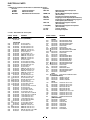
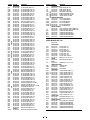
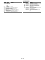
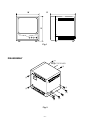
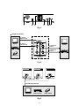
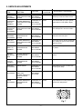
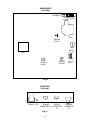
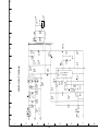
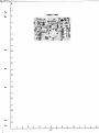
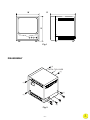
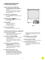
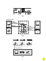
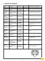
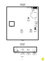
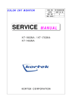
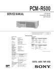
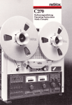
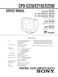
B/W Video Monitor
VM-6614
VM-6615P
INDEX
1. SAFETY PRECAUTIONS
SPECIFICATIONS
DISASSEMBLY
OPERATING INSTRUCATIONS
SERVICE ADJUSTMENTS
2. PARTS LIST
3.
BLOCK DIAGRAMS, CIRCUIT DIAGRAMS
4.
PRINTED WIRING BOARDS
I
i n d ex
Click on this button found on the first page of each file
to return to this screen.
FILE NO.
SERVICE MANUAL
B/W Video Monitor
VM-6614
(Product Code : 114 901 31)
(U.S.A, Canada)
VM-6615P
(Product Code : 114 901 34)
(Europe)
(Product Code : 114 901 36)
(U.K.)
(Product Code : 114 901 38)
(Australia)
CONTENTS
SPECIFICATIONS .................................................................... 3
1. OPERATING INSTRUCTIONS ............................................. 5
2. SERVICE ADJUSTMENTS ................................................... 7
3. PARTS LIST ......................................................................... 9
4. CIRCUIT DIAGRAMS ......................................................... 13
NOTE: 1. Parts order must contain model number, part number, and description.
2. Substitute parts may be supplied as the service parts.
3. N.S.P. : Not available as service parts.
Design and specifications are subject to change without notice.
I
i n d ex
L8MAC/US,XE,UK,AU
REFERENCE No.SM5310264
3. PARTS LIST
Note:
Alphabetic caracters enclosed by ( ) in the descriptions indicate destination for the VM-6615P.
VM-6615P(AU): Australia
VM-6615P(XE): Europe
VM-6615P(UK): United Kingdom
VM-6614: NTSC area (U.S.A., Canada)
CABINET & CHASSIS PARTS
LOCATION PARTS NO.
DESCRIPTION
LOCATION PARTS NO.
DESCRIPTION
1
645 046 5215
1
645 047 0660
2
645 046 0487
2
3
645 047 0622
645 046 0494
16
17
18
19
20
21
22
645 034 4619
645 034 3582
645 034 3919
645 034 3582
645 034 3841
645 034 4299
645 046 6007
3
4
645 047 0639
645 046 5178
4
645 047 0608
5
5
6
7
645 046 0432
645 047 0547
645 046 6496
645 034 3810
8
9
10
10
11
12
13
14
15
645 034 3605
645 034 3575
645 046 5864
645 046 5857
645 046 6038
645 046 6175
645 046 6182
645 034 3599
645 046 5413
FRONT PANEL MT-15S OC-00067 [VM-6614,
VM-6615P(UK)]
FRONT PANEL MT-15S AA-51 [VM-6615P(AU),
(XE)]
VR KNOB VR MT-9 OC-00067 [VM-6614,
VM-6615P(UK)]
VR KNOB VR MT-9 AA-51 [VM-6615P(AU), (XE)]
SW KNOB MT-9 OC-00067 [VM-6614,
VM-6615P(UK)]
SW KNOB MT-9 AA-51 [VM-6615P(AU), (XE)]
DECORATED PLATE MT-20 OC-00067 [VM-6614,
VM-6615P(UK)]
DECORATED PLATE MT-20 AA-51
[VM-6615P(AU), (XE)]
LOGO MT-9OC-00067 [VM-6614, VM-6615P(UK)]
LOGO MT AL AA-51 [VM-6615P(AU), (XE)]
VR ASS’Y MT-15S
POWER SWITCH SS-160-7 (Included in the
VR ASS’Y)
RH W/W SCR. 3*8MM
PH W/W SCR. 3*8MM
CRT MI1547P4AU CPT
CRT MI1546P4AU CPT
YOKE MM-15A
L TYPE MM-15A (L)
L TYPE MM-15A (R)
PH W/W SCR. 4*18MM
CRT GND WIRE/1015 22AWG (N.S.P.)
23
24
25
26
27
28
29
30
31
32
33
34
35
36
37
38
39
40
41
42
645 034 3612
645 035 6223
645 046 0401
645 046 0418
645 034 4626
645 034 3605
645 034 3926
645 034 4657
645 035 6216
645 046 6519
645 046 6403
645 038 5599
645 034 3582
645 035 9422
645 035 9415
645 046 4942
645 046 4898
645 047 9540
645 046 0500
645 047 9564
METAL CABINET CM-14
PH W/W SCR. 4*8MM
HANDLE COVER CM-14 PA-765A
PH W/W SCR. 4*8MM
ID LABEL 83*51MM (N.S.P.)
PCB GUIDE RAIL PCB MM-12A
FBT TRANS. CEM-15A CBC (Included in the
main board)
SCREW+WASHER 3*6MM
WASHER OUT TEETH 4.5*8.5*0.5MM
BNC CONNECTOR BNC 13-28 75OHM
SLIDE SWITCH SS004-P012BJ-PA6
BASE CM-14+Y/C (N.S.P.)
RH W/W SCR. 3*8MM
FOOT PAD RIVET MM-12A GL-24H
FOOT PAD GL-24H
BH SCREW 4*6MM
AC SOCKET ASS’Y MM-15A
JACK PLATE MM-15S AA-51
SHRINK TUBE 2.5DIA. (N.S.P.)
PH W/W SCR. 4*8MM
PCB HOLDER PCB CM-14A (L)
PCB HOLDER PCB CM-14A (R)
WASHER IN TEETH 13*17*0.6MM
NUT 12*14*2.5MM
VIDEO BOABD MT-15S
LED LENS MT-9/12/15/20
MAIN BOARD MT-15S (NORMAL)
N.S.P.: Not available as service parts.
1
2
3
5
4
10
11
12
14 15
13
41
6
16
17
18
7 8
40
21
19
20
22
36
23
42
27
28
3734
38
9
35
30
29
VM-6614
33
26
39
31
24
32
25
9
ELECTRICAL PARTS
Note:
1. Materials of Capacitors and Resistors are abbreviated as follows ;
Resistors
Capacitors
CF RES
Carbon Film Resistor
MEF CAP
MF RES
Metal Film Resistor
MOF RES
Metallized Oxide Film Resistor
MEMB CAP
PEI CAP
PPN CAP
PPS CAP
MPP CAP
X CAP(MKP)
CC CAP
EC CAP
Metallized Polyester Film Capacitor
(Non-inductive)
Mini Box Metallized Polyester Capacitor
(Non-inductive)
Polyester Film Capacitor (Inductive)
Polypropylene Film Capacitor (Non-inductive)
Polypropylene and Metallized Polypropylene
Film Capacitor (Non-inductive)
Metallized Polypropylene Capacitor
(Non-inductive)
Metallized Polypropylene Film Capacitor
(Non-inductive)
Ceramic Capacitor
Electrolytic Capacitor
2. N.S.P. : Not available as service parts.
LOCATION PARTS NO.
DESCRIPTION
LOCATION PARTS NO.
C924
MAIN BOARD MT-15S (NORMAL)
645 047 9564
C207
C208
C301
C302
C303
C304
C305
C306
C307
C308
C309
C310
C311
C312
C313
C401
C402
C403
C404
C405
C406
C407
C408
C409
C410
C411
C412
C413
C414
C415
C416
C417
C419
C421
C422
C430
C902
C902
C903
C904
C906
C907
C908
C910
C913
C915
C917
C918
C920
C923
(CAPACITORS)
645 034 2738
645 034 2714
645 040 8991
645 046 4058
645 046 4287
645 034 3025
645 034 2615
645 046 3938
645 034 3025
645 046 4287
645 046 4287
645 046 4287
645 046 3778
645 034 2653
645 047 0530
645 046 4027
645 034 2783
645 034 2677
645 034 3018
645 046 0074
645 046 4287
645 046 4287
645 034 2783
645 046 4041
645 046 4140
645 046 3761
645 046 4201
645 034 2783
645 034 2950
645 043 3139
645 046 3648
645 046 3570
645 034 2776
645 034 2875
645 043 3139
645 046 3891
645 046 4331
645 046 4348
645 034 3087
645 034 3087
645 034 3087
645 045 9948
645 034 2622
645 043 3139
645 046 3877
645 046 4287
645 034 3018
645 034 3018
645 046 4119
645 046 3617
D301
D401
D402
OR
D403
OR
D404
D405
D406
D408
OR
D901
D902
D903
D904
D905
D906
OR
D910
OR
ZD901
D914
OR
D915
EC CAP 2.2UF 50 V
EC CAP 220UF 16 V
PEI CAP .033UF 50V +/-5%
PEI CAP .068UF 50V +/-5%
MEMB CAP .1UF 63V +/-5%
MEMB CAP .22UF 63V +/-5%
EC CAP 100UF 25 V
CC CAP 33PF 50V +/-5%
MEMB CAP .22UF 63V +/-5%
MEMB CAP .1UF 63V +/-5%
MEMB CAP .1UF 63V +/-5%
MEMB CAP .1UF 63V +/-5%
EC CAP 4.7UF 25 V
EC CAP 1000UF 16V 10DIA.
EC CAP 2200UF 16V <=13DIA.
PEI CAP .0033UF 50V +/-5%
EC CAP 470UF 16 V
EC CAP 1UF 50 V
MEMB CAP .01UF 63V +/-5%
PPN CAP .0056UF 50V +/-5%
MEMB CAP .1UF 63V +/-5%
MEMB CAP .1UF 63V +/-5%
EC CAP 470UF 16 V
PEI CAP .056UF 50V +/-5%
MEF CAP 2.7UF 100V +/-5%
EC CAP 470UF 25V 105C
PPN CAP .027UF 630V +/-5%
EC CAP 470UF 16 V
PEI CAP .022UF 50V +/-5%
CC CAP 103PF 1.5KV Z5U
EC CAP 1UF 160 V
EC CAP 47UF 160V +/-20%13*21
EC CAP 47UF 16 V
CC CAP 681PF 50V Y5P
CC CAP 103PF 1.5KV Z5U
CC CAP 561PF 1KV Y5P
X CAP .22UF 250V +/-10%22.5M
X CAP .22UF 275V +/-10%22.5M
Y CAP 472PF 400V +/-20%
Y CAP 472PF 400V +/-20%
Y CAP 472PF 400V +/-20%
EC CAP 100UF 400V 22DIA.
EC CAP 100UF 35 V
CC CAP 103PF 1.5KV Z5U
CC CAP 391PF 50V Y5P
MEMB CAP .1UF 63V +/-5%
MEMB CAP .01UF 63V +/-5%
MEMB CAP .01UF 63V +/-5%
MEF CAP .22UF 50V +/-5% 7.5MM
EC CAP 1000UF 16V 105C
F901
IC301
IC401
IC901
L401
OR
OR
L402
OR
OR
L403
L905
L905
OR
PIN
Q205
OR
Q401
Q402
Q403
Q405
Q406
Q901
10
DESCRIPTION
645 034 2783
EC CAP 470UF 16 V
(DIODES)
645 034 3377
RECTIFIER DIODE 1N4003
645 046 4669
RECTIFIER DIODE PS154R
645 046 4690
RECTIFIER DIODE UF5402G
645 046 0289
RECTIFIER DIODE 30DF2
645 034 3315
DIODE 1N4148
645 034 3308
DIODE 1N4148
645 046 4652
RECTIFIER DIODE 15DF6
645 034 3346
RECTIFIER DIODE BYT52M T52MM
645 046 4669
RECTIFIER DIODE PS154R
645 034 3315
DIODE 1N4148
645 034 3308
DIODE 1N4148
645 046 0241
RECTIFIER DIODE 1N4007
645 046 0241
RECTIFIER DIODE 1N4007
645 046 0241
RECTIFIER DIODE 1N4007
645 046 0241
RECTIFIER DIODE 1N4007
645 046 0258
RECTIFIER DIODE BA159
645 040 9141
RECTIFIER DIODE PG102R
645 046 4645
RECTIFIER DIODE PS104R
645 034 3315
DIODE 1N4148
645 034 3308
DIODE 1N4148
645 046 4607
ZENER DIODE HZ20-2
645 046 4690
RECTIFIER DIODE UF5402G
645 046 0289
RECTIFIER DIODE 30DF2
645 046 4591
DIODE 1N4606
(FUSE)
645 046 0821
FUSE 2A/250V SLOWBLOW 5*20MM
(INTEGRATED CIRCUIT)
645 046 0128
LINEAR IC TDA1175P
645 046 0104
LINEAR IC LM1391N
645 034 3094
LINEAR IC UC3842AN
(COILS)
645 046 0876
CHOCK COIL 20 UH +/-20%
645 046 0883
CHOCK COIL 20 UH +/-20%
645 046 0890
CHOCK COIL 20 UH +/-20%
645 046 0838
WIDTH COIL VM-14AF
645 046 0852
WIDTH COIL VM-14AF
645 046 0845
WIDTH COIL VM-14AF
645 046 0869
LINEARITY COIL 15 UH +/-20%
645 046 0876
CHOCK COIL 20 UH +/-20%
645 046 0883
CHOCK COIL 20 UH +/-20%
645 046 0890
CHOCK COIL 20 UH +/-20%
645 046 0371
CONNECTOR BASE 1038H
(SEMICONDUCTORS)
645 046 4508
TR 2SA1015GR
645 034 3209
TR 2SA733P
645 034 3216
TR 2SC1815GR
645 046 0159
TR 2SC1959Y
645 046 4546
TR 2SC4106M
645 046 0197
TR 2SD1609C
645 046 0197
TR 2SD1609C
645 040 9127
FET SSS7N60A
LOCATION PARTS NO.
R201
R222
R223
R224
R225
R226
R227
R301
R302
R303
R304
R305
R306
R307
R308
R309
R310
R311
R313
R314
R316
R317
R401
R402
R403
R404
R405
R408
R409
R410
R411
R412
R413
R414
R415
R416
R417
R420
R421
R422
R423
R424
R425
R427
R428
R429
R430
R431
R433
R434
R435
R436
R437
R491
R901
R902
R903
R907
R909
R911
R913
R914
R917
R918
R919
R921
R923
R924
R925
R926
R927
R930
R931
R932
SW201
(RESISTORS)
645 034 2356
645 045 9610
645 045 9764
645 034 2028
645 034 2271
645 034 2271
645 034 1861
645 034 2042
645 034 2042
645 034 2202
645 046 3310
645 040 8786
645 045 9696
645 045 9726
645 045 9726
645 046 2948
645 040 8724
645 046 2801
645 034 2127
645 046 2856
645 034 1892
645 034 2370
645 034 1861
645 034 2288
645 034 2325
645 034 1922
645 034 2363
645 034 1984
645 045 9597
645 045 9726
645 034 2288
645 034 2073
645 038 5353
645 046 2436
645 034 2363
645 046 2870
645 046 3211
645 046 2986
645 046 2207
645 040 8823
645 034 2257
645 046 2412
645 040 8816
645 045 9580
645 046 2603
645 046 3051
645 046 3440
645 046 3372
645 034 1878
645 045 9733
645 046 2641
645 046 3471
645 038 5360
645 034 1991
645 046 2818
645 045 9924
645 046 3402
645 034 2547
645 034 2011
645 034 1892
645 034 2455
645 034 1861
645 034 2042
645 040 8816
645 034 1984
645 034 1892
645 034 2226
645 034 1984
645 034 2271
645 034 2387
645 034 2288
645 034 1861
645 046 3389
645 046 3389
(SWITCH)
645 046 0418
DESCRIPTION
LOCATION PARTS NO.
CF RES 75OHM 1/4W +/-5%
CF RES 200OHM 1/4W +/-5%
CF RES 680KOHM 1/4W +/-5%
CF RES 220OHM 1/4W +/-5%
CF RES 560OHM 1/4W +/-5%
CF RES 560OHM 1/4W +/-5%
CF RES 1KOHM 1/4W +/-5%
CF RES 2.2KOHM 1/4W +/-5%
CF RES 2.2KOHM 1/4W +/-5%
CF RES 4.3KOHM 1/4W +/-5%
MOF RES 3.3OHM 1W +/-5%
CF RES 220KOHM 1/4W +/-5%
CF RES 3.3OHM 1/4W +/-5%
CF RES 56KOHM 1/4W +/-5%
CF RES 56KOHM 1/4W +/-5%
CF RES 62KOHM 1/4W +/-5%
CF RES 1OHM 1/2W +/-5%
CF RES 470KOHM 1/4W +/-5%
CF RES 30KOHM 1/4W +/-5%
CF RES 510KOHM 1/4W +/-5%
CF RES 100KOHM 1/4W +/-5%
CF RES 82KOHM 1/4W +/-5%
CF RES 1KOHM 1/4W +/-5%
CF RES 5.6KOHM 1/4W +/-5%
CF RES 6.8KOHM 1/4W +/-5%
CF RES 12KOHM 1/4W +/-5%
CF RES 820OHM 1/4W +/-5%
CF RES 15KOHM 1/4W +/-5%
CF RES 150OHM 1/4W +/-5%
CF RES 56KOHM 1/4W +/-5%
CF RES 5.6KOHM 1/4W +/-5%
CF RES 2.4KOHM 1/4W +/-5%
CF RES 1.8KOHM 1/4W +/-5%
CF RES 2KOHM 1/2W +/-5%
CF RES 820OHM 1/4W +/-5%
CF RES 56OHM 1/4W +/-5%
MOF RES 20OHM 3W +/-5%
CF RES 680OHM 1/2W +/-5%
CF RES 10KOHM 1/2W +/-5%
CF RES 620OHM 1/4W +/-5%
CF RES 47KOHM 1/4W +/-5%
CF RES 180KOHM 1/4W +/-5%
CF RES 470OHM 1/4W +/-5%
CF RES 1MOHM 1/4W +/-5%
CF RES 300KOHM 1/4W +/-5%
CF RES 8.2KOHM 1/2W +/-5%
MOF RES 6.8KOHM 1W +/-5%
MOF RES 4.7KOHM 1W +/-5%
CF RES 10KOHM 1/4W +/-5%
CF RES 560KOHM 1/4W +/-5%
CF RES 330KOHM 1/4W +/-5%
MOF RES 82KOHM 3W +/-5%
CF RES 910OHM 1/4W +/-5%
CF RES 150KOHM 1/4W +/-5%
CF RES 470KOHM 1/2W +/-5%
W-W RES 3.9OHM 3W +/-5% 5MM
MOF RES 0.47OHM 1W +/-5%
CEMENT RES 10KOHM 5W +/-5% 5MM
CF RES 22OHM 1/4W +/-5%
CF RES 100KOHM 1/4W +/-5%
MOF RES 1OHM 2W +/-5%
CF RES 1KOHM 1/4W +/-5%
CF RES 2.2KOHM 1/4W +/-5%
CF RES 470OHM 1/4W +/-5%
CF RES 15KOHM 1/4W +/-5%
CF RES 100KOHM 1/4W +/-5%
CF RES 47OHM 1/4W +/-5%
CF RES 15KOHM 1/4W +/-5%
CF RES 560OHM 1/4W +/-5%
CF RES 91OHM 1/4W +/-5%
CF RES 5.6KOHM 1/4W +/-5%
CF RES 1KOHM 1/4W +/-5%
MOF RES 47KOHM 2W +/-5%
MOF RES 47KOHM 2W +/-5%
T401
OR
OR
T402
T901
OR
T902
VR301
VR302
VR303
VR401
VR402
VR404
OR
B301
B401
B901
B902
BNC02
DESCRIPTION
(TRANSFORMERS)
645 046 0777
DRIVE TRANS. VM-14AF
645 046 0784
DRIVE TRANS. VM-14AF
645 046 0791
DRIVE TRANS. VM-14AF
645 046 6007
FBT TRANS. CEM-15A CBC
645 046 5901
POWER TRANS. MM-12A VDE
645 046 5925
POWER TRANS. MM-12A VDE
645 046 0920
LINE FILTER TM-14T 20MH
(VARIABLE RESISTORS)
645 046 4744
POT VR 100KOHM 6DIA.
645 046 0340
POT VR 500KOHM 6DIA.
645 046 4812
POT VR 50KOHM 6DIA.
645 034 3513
POT VR 5KOHM 6DIA.
645 046 0340
POT VR 500KOHM 6DIA.
645 046 0326
POT VR 2MOHM15DIA.
(MISCELLANEORS)
645 034 4404
FUSE CLIP BOARD TYPE 5*20MM (F901)
645 034 4404
FUSE CLIP BOARD TYPE 5*20MM (F901)
645 034 3773
CONNECTOR BASE M241855
645 046 0395
CONNECTOR BASE M11384
645 046 4997
CONNECTOR BASE M241835-X
645 034 3735
CONNECTOR BASE M241833-X
645 034 3674
CONNECTOR BASE M241852
VIDEO BOABD MT-15S
645 047 9540
C201
C202
C203
C204
C205
C206
C213
C219
C220
D201
L201
Q201
Q203
Q204
R202
R203
R204
R206
R210
R211
R212
R213
R214
R215
R216
R217
R218
R219
R220
R230
R231
R232
SP201
SP202
S201
B201
B202
B203
B204
GND
SLIDE SWITCH SS004-P012BJ-PA6
11
(CAPACITORS)
645 034 2684
EC CAP 22UF 16 V
645 034 2714
EC CAP 220UF 16 V
645 034 2714
EC CAP 220UF 16 V
645 046 3594
EC CAP 1000UF 10 V
645 046 0012
CC CAP 272PF 50V Y5P
645 034 2608
EC CAP 100UF 16 V
645 045 9986
EC CAP 4.7UF 160 V
645 043 3139
CC CAP 103PF 1.5KV Z5U
645 046 4171
MEF CAP .47UF 100V +/-5%
(DIODE)
645 034 3377
RECTIFIER DIODE 1N4003
(COIL)
645 046 0913
PEAKING COIL 4.7 UH +/-10%
(SEMICONDUCTORS)
645 034 3216
TR 2SC1815GR
645 046 0203
TR 2SD667C
645 046 0197
TR 2SD1609C
(RESISTORS)
645 034 2059
CF RES 22KOHM 1/4W +/-5%
645 034 1984
CF RES 15KOHM 1/4W +/-5%
645 045 9566
CF RES 100OHM 1/4W +/-5%
645 034 2165
CF RES 390OHM 1/4W +/-5%
645 034 2226
CF RES 47OHM 1/4W +/-5%
645 034 1847
CF RES 10OHM 1/4W +/-5%
645 034 1984
CF RES 15KOHM 1/4W +/-5%
645 034 2103
CF RES 2.7KOHM 1/4W +/-5%
645 046 2535
CF RES 27OHM 1/4W +/-5%
645 046 2979
CF RES 68OHM 1/4W +/-5%
645 034 1977
CF RES 1.5KOHM 1/4W +/-5%
645 034 1977
CF RES 1.5KOHM 1/4W +/-5%
645 046 3266
MOF RES 2.4KOHM 2W +/-5%
645 034 2028
CF RES 220OHM 1/4W +/-5%
645 046 2955
CF RES 6.2OHM 1/2W +/-5%
645 046 3433
MOF RES 56KOHM 1/2W +/-5%
645 045 9702
CF RES 47KOHM 1/2W +/-5%
645 045 9573
CF RES 1KOHM 1/2W +/-5%
(SPARK GAPS)
645 035 9408
SPARK GAP DSP 200V +/-10%
645 035 9392
SPARK GAP 0.75PF 1KV +/-10%
(MISCELLANEOUS)
645 046 0524
CRT SOCKET CRT 7PIN 20DIA.
645 046 0388
CONNECTOR BASE M241854
645 034 3773
CONNECTOR BASE M241855
645 046 5000
CONNECTOR BASE M241856-X
645 034 3674
CONNECTOR BASE M241852
645 034 3667
CONNECTOR BASE P235142
ACCESSORIES
LOCATION PARTS NO.
DESCRIPTION
LOCATION PARTS NO.
645 046 0463
645 047 0615
645 038 5933
645 034 3971
645 040 9257
VR ASS’Y MT-15S
645 046 6496
LED1
SW202
SW901
VR406
VR201
B703
(LED)
645 046 0296
LED 5DIA.
(SWITCH)
645 046 0425
ROTARY SWITCH 296S0947B
645 034 3810
POWER SWITCH SS-160-7
(VARIABLE RESISTORS)
645 046 0319
VR 200KOHM 9DIA. 10 MMND F 15
645 046 0302
VR 500OHM 9DIA. 10 MMND F 15
(MISCELLANEOUS)
645 046 0388
CONNECTOR BASE M241854
645 040 9264
645 035 6254
645 034 4336
645 046 5161
645 047 0592
12
DESCRIPTION
USER MANUAL CCTV [VM-6614]
USER MANUAL CCTV [VM-6615P(AU), (UK), (XE)]
POWER CORD NS8-5175N [VM-6614]
POWER CORD 10-1 VDE [VM-6615P(XE)]
POWER CORD NS8-5180N (AUSTRALIA)
[VM-6615P(AU)]
POWER CORD NS8-5181N(U.K.) [VM-6615P(UK)]
PE BAG 15" 406*406*900MM
POLYFORM CM-14A
CARTON MT-15S-EIA [VM-6614]
CARTON MT-15S-CCIR [VM-6615P(AU), (UK),
(XE)]
FILE NO.
SERVICE MANUAL
B/W Video Monitor
VM-6614
(Product Code : 114 901 31)
(U.S.A, Canada)
VM-6615P
(Product Code : 114 901 34)
(Europe)
(Product Code : 114 901 36)
(U.K.)
(Product Code : 114 901 38)
(Australia)
CONTENTS
SPECIFICATIONS .................................................................... 3
1. OPERATING INSTRUCTIONS ............................................. 5
2. SERVICE ADJUSTMENTS ................................................... 7
3. PARTS LIST ......................................................................... 9
4. CIRCUIT DIAGRAMS ......................................................... 13
NOTE: 1. Parts order must contain model number, part number, and description.
2. Substitute parts may be supplied as the service parts.
3. N.S.P. : Not available as service parts.
Design and specifications are subject to change without notice.
L8MAC/US,XE,UK,AU
REFERENCE No.SM5310264
SAFETY PRECAUTIONS
WARNING:
Service should not be attempted by anyone unfamiliar with the necessary precautions for this recording or playback
equipment. The following precautions are necessary during servicing:
1.
Many electrical and mechanical parts in this recorder have
special safety-related characteristics for providing protection against shock, fire and other hazards. These characteristics often go unnoticed in a visual inspection, and the
protection afforded by them cannot necessarily be obtained by using replacement components with higher ratings (voltage, wattage, etc.).
2.
Replacement parts having special safety-related characteristics are identified in this manual, and in the schematic
diagrams, by the symbol ! . These components have
values that are of special significance to product safety.
Should any component (identified by the symbol
) need
to be replaced, use only the part designated in the parts
List. Do not deviate from the specified resistance, wattage,
and voltage ratings.
3.
Before returning the set to the customer, always perform an
AC leakage current check on the exposed metallic parts of
the cabinet, such as terminals, screwheads, metal overlays, etc. to be sure that the set is safe to operate without
the danger of electrical shock, Plug the AC line cord directly
into a 120 V AC outlet. (Do not use a line isolation transformer during this check.) Use an AC voltmeter with a
sensitivity of 5000 ohms per volt (or more) as follows:
Connect a 1500 ohms, 10 watt resistor, paralleled by a 0.15
mfd, 150 VAC capacitor, between a known good earth
ground (water pipe, conduit, etc.) and the exposed metallic
parts, one at a time. Measure the AC voltage across the
1500 ohms resistor and 0.15 mfd capacitor combination.
Reverse the AC plug at the AC outlet and repeat the AC
voltage measurements for each exposed metallic part. The
measured voltage must not exceed 300 mVrms. This
corresponds to 200 µA AC. Any value exceeding this limit
constitutes a potential shock hazard and must be corrected
immediately.
4.
Fuse symbol marks.
For CANADA
Video
Monitor
For U.S.A.
Fuse rating is marked at
adjacent fuse.
UNDERWRITERS LABORATORIES Standard
CAUTION
–2–
"Risk of fire-replace fuse as marked"
SPECIFICATIONS
VM-6614
System :
Picture tube :
Resolution :
Scanning frewuency :
Input terminals :
VIDEO A
VIDEO B
Outout terminals :
VIDEO A
VIDEO B
Sub Adjusting control :
Termination switch :
Operating environment :
Power source :
Power consumption :
Dimension (W x H x D ) :
Weight :
EIA standard
15˝ measured diagonally, 90° deflection angle
More than 1000 TV lines (center)
Horizontal: 15.75 kHz (EIA), Vertical: 60 Hz (EIA)
Composite video: 1 line, BNC connector, 1.0 V p-p 75 ohm negative sync
Composite video: 1 line, BNC connector, 1.0 V p-p 75 ohm negative sync
Composite video: 1 line, BNC connector, 1.0 V p-p 75 ohm negative sync
Composite video: 1 line, BNC connector, 1.0 V p-p 75 ohm negative sync
Sub bright volume
Vertical size volume
Vertical hold volume
Manual switchable, Hi/ 75 ohm (Lo)
Temperature: -10 °C to 40 °C, Humidity:10% to 90 %
AC 100 to 240 V 50/60 Hz
35 Watts
350 x 350 x 360 mm
11 kg
VM-6615P
System :
Picture tube :
Resolution :
Scanning frewuency :
Input terminals :
VIDEO A
VIDEO B
Outout terminals :
VIDEO A
VIDEO B
Sub Adjusting control :
Termination switch :
Operating environment :
Power source :
Power consumption :
Dimension (W x H x D ) :
Weight :
CCIR standard
15˝ measured diagonally, 90° deflection angle
More than 1000 TV lines (center)
Horizontal: 15.625 kHz (CCIR), Vertical: 50 Hz (CCIR)
Composite video: 1 line, BNC connector, 1.0 V p-p 75 ohm negative sync
Composite video: 1 line, BNC connector, 1.0 V p-p 75 ohm negative sync
Composite video: 1 line, BNC connector, 1.0 V p-p 75 ohm negative sync
Composite video: 1 line, BNC connector, 1.0 V p-p 75 ohm negative sync
Sub bright volume
Vertical size volume
Vertical hold volume
Manual switchable, Hi/ 75 ohm (Lo)
Temperature: -10 °C to 40 °C, Humidity:10% to 90 %
AC 100 to 240 V 50/60 Hz
35 Watts
350 x 350 x 360 mm
11 kg
–3–
D
H
W
Fig. 1
DISASSEMBLY
Fig. 2
–4–
1. OPERATING INSTRUCTIONS
1-1. FRONT PANEL CONTROLS
1. Monitor Selector Switch (VIDEO A/B)
Turn this Monitor selector switch A position for a
signal fed through the rear panel VIDEO A
connectors.
Then, turn this Monitor selector switch B position for a signal fed through the rear panel
VIDEO B connectors.
2. Contrast Control (
CONTRAST)
Turn to adjust picture contrast according to your
requirement.
3. Brightness Control (
BIRGHT)
Turn to adjust picture brightness according to
your requirement.
4. Power Indicator
Lights when the power is on.
Lit: When the power is on.
Unlit: When the power is off.
1
2
3 4 5
Fig. 3
5. Power Switch (POWER)
Press this switch to turn the power on or off.
1-2. REAR PANEL CONTROLS & CONNECTION
However, the last monitor termination switch
should be the 75 ohm position for proper line
termination.
1. AC input socket (AC INPUT)
Connect the AC power cord (supplied) securely
to this socket and to a wall outlet.
6. Sub-brightness control (SUB-BRI)
2. Video input terminals (VIDEO IN)
These terminals are used to input a video signal
source to this monitor.
Connect to the video output of a VCR or another monitor (for loop through connection) or to
a video camera.
Turn to adjust picture brightness.
7. Vertical Size control (V-SIZE)
Turn to adjust picture vertical size of the picture.
8. Vertical hold control (V-HOLD)
If the picture is scrolling up or down on the
screen, turn this control until there is a single
steady picture.
3. Video output terminals (VIDEO OUT)
These terminals are used to output a video
signal for this monitor.
Loop-through output of the video in BNC
connector, then connect to the video input of
another monitor or a VCR.
4. Termination Switch (HI/75 Ω (Lo))
Select the input impedance (HI/75 ohm).
When using only one monitor, turn the termination switch to the 75 ohm position. When using
more than one monitor, set all of the termination
switch to the monitors to the HI position.
–5–
1
4
3
2
68 7
Fig. 4
Single Connection
To Video B
INPUT terminal
(Video signal cable)
Monitor
To Video A
INPUT terminal
Monitor
To Video input
terminal
(Video signal cable)
Video recorder
To Video input
terminal
Video recorder
Video camera
(Rear panel)
Fig. 5
Coaxial cable
To Video input terminal
Monitor
Video recorder
Fig. 6
–6–
Video camera
2. SERVICE ADJUSTMENTS
ADJUSTMENT
ITEM
TIMING
PATTERN
VR
LOCATION
SETTING
ADJUSTMENT PROCEDURE
VERTICAL
LINEARITY
ADJUSTMENT
CONTRAST VR
PATTERN GENERATOR
MODE CROSS-HATCHED AND BRIGHT
VR TO CENTER.
PATTERN
VR303
Adjust VR303 to make equal distance
between top-center and bottom-center.
HORIZONTAL
HOLD ADJUSTMENT
CONTRAST VR
PATTERN GENERATOR
MODE CROSS-HATCHED AND BRIGHT
VR TO CENTER.
PATTERN
VR401
Turn off horizontal sync. (pin to ground)
Adjust VR401 to make pattern upright.
GEOMETRICE
DISTORTION
PATTERN
ADJUSTMENT
CONTRAST VR
PATTERN GENERATOR
MODE CROSS-HATCHED AND BRIGHT
VR TO CENTER.
PATTERN
Adjust eigth magnets on the deflection
yoke make picture to the best condition.
VIDEO
CENTERING
ADJUSTMENT
PATTERN GENERATOR
MODE MONOSCPE
PATTERN
CONTRAST VR
AND BRIGHT
VR TO CENTER.
The video is centered by roating the two
small at the rear of the yoke.
VIDEO TILT
ADJUSTMENT
CONTRAST VR
PATTERN GENERATOR
MODE CROSS-HATCHED AND BRIGHT
VR TO CENTER.
PATTERN
HORIZONTAL
WIDTH ADJUSTMENT
PATTERN GENERATOR
MODE MONOSCPE
PATTERN
CONTRAST VR
AND BRIGHT
VR TO CENTER.
L402
Adjust L402 to make picture width within
"2" position.
VERTICAL
SIZE ADJUSTMENT
PATTERN GENERATOR
MODE MONOSCPE
PATTERN
CONTRAST VR
AND BRIGHT
VR TO CENTER.
VR302
Adjust VR302 make height to "1.5"
position.
VERTICAL
HOLD ADJUSTMENT
PATTERN GENERATOR
MODE MONOSCPE
PATTERN
CONTRAST VR
AND BRIGHT
VR TO CENTER.
VR301
Adjust VR301 to make pattern stop rolling.
NTERLACE
ADJUSTMENT
CAMERA SIGNAL
CONTRAST VR
AND BRIGHT
VR TO CENTER.
VR301
Adjust VR301 have gap of vertical scan
line distinguish clearly.
RASTER
ADJUSTMENT
DISCONNECT VIDEO
SIGNAL AND
PATTERN GENERATOR
MODE FULL-WHITE
PATTERN
CONTRAST VR
AND BRIGHT
VR TO MAX.
VR402
Adjust VR402 to the suitable brightness.
FOCUS
ADJUSTMENT
PATTERN GENERATOR
MODE MONOSCPE
PATTERN
CONTRAST VR
AND BRIGHT
VR TO CENTER.
VR404
Adjust VR404 have control picture and 4
corners to be distinguished.
Loosen the screw on the rear of deflection
yoke, rotating the yoke to correct position
tighten the screw.
1
3
5
1
3
5
1357
7531
5
3
1
5
3
1
Fig. 7
–7–
MAIN BOARD
(Foil side)
VR402
SUB-BRITE
VR301 VR302
V-HOLD V-SIZE
T402
VR404
FOCUS
L402
T901
E
C
B
VR301
V-LINE
VR401
H-HOLD
Fig. 8
SW901 LED1
Q403
MAIN BOARD
VR BOARD
(Foil side)
VR BOARD
VR201
VR406
BRIGHTNESS CONTRAST
SW202
CHANNEL
Fig. 9
–8–
4
-14-
B
SW202
5
R405
820
R404
12K
C401
.0033µ
50V
R403
6.8K
C402
470µ
16V
R401
1K
MAIN_PWB
R201
75
SW201
VR_PWB
A
B+ 12V
6
3
1
8
2
6
4
7
5
R410
56K
R411
5.6K
R408
15K
Q401
C1815
R226
560
R225
560
R413
1.8K
7
C421
681P
R437
910
C408
470µ
16V
R412 C419
2.4K 47µ
16V
R417
20
3W
T401
R304
3.3
1W
C204
1000µ
10V
R215
68
Q406
D1609
R435
330K
2
R306
3.3
R421
10K
1/2W
R436
82K
3W
C422
103P
1.5KV
L401
C413
470µ
16V
C411
470µ
25V
10
9
4
T402
6
3
2
7
8
D401
PS154R
C415
103P
1.5KV
C416
1µ
160V
D406
PS154R
D405
BYT52M
FBT
SP201
R308
56K
C417
47µ
160V
C311
4.7µ
25V
V-DY
R424
180K
R231
47K
1/2W
R461
150K
VR404
2M
FACUS
R427
1M
VR_PWB
R430
6.8K
1W
R423
47K
D403
1N4148
R425 R429
8.2K
470
1/2W
VR406
200K
R428
300K
R422
620
D408
1N4148
R230
56K
1/2W
R232
1K
1/2W
VIDEO_PWB
CRT
VR402
500K
C219
103P
1.5KV
SP202
1KV
R219
220
C312
R307 1000µ
16V
56K
C220
0.47µ
100V
MAIN_PWB
C213
4.7µ
160V
R218
2.4K
2W
L201
4.7µH
R220
6.2
1/2W
VR303 R310
B50K 1
1/2W
R313
C313
C310 30K
2200µ
0.1µ
16V
50V
C309
0.1µ
50V
D402
UF5402G
C412
0.027µ
630V
VR304
100K
V-SIZE
R317
82K
R316
100K
C414
0.22µ
12V
15
7
C206
100µ
16V
C306
33P
50V
R305
220K
R217
1.5K
R216
1.5K
Q204 D1609
C307 C308
0.22µ 0.01µ
6 50V
50V
GND
4,5,12,13
C305
IC301
100µ
14
TDA1175P
25V
R311
3
V-DEF.
470K
R309
10
62K
11
1
9
16
8
C205
272P
R214
27
Q203
D667C
VR301
B100K
C410
2.7µ
100V
Q403
C4106
C304
0.22µ
50V
C303
0.01µ
50V
D301
1N4003
R212
15K
R303
4.3K
C409
0.056µ
50V
R434
560K
R416
56
C430
560P
1KV
L403
H-LIN
C302
0.068µ
50V
R302
2.2K
R213
2.7K
C203
220µ
16V
R224
220
Q405
D1609
R433
10K
R415
820
Q402
C1959Y
R414
2K
1/2W
R431
4.7K
1W
R420
680
1/2W
L402
H-WIDTH
C301
0.33 µ
50V
R301
2.2K
C208
220µ
16V
R211
10
VR_PWB
CONT VR201
B500
R210
47
Q205
A1015
R223
680K
R206
390
C202
220µF
16V
Q201
C1815
C406
0.1µ
C405 50V C407
0.1µ
.0056µ
50V
50V
C404
0.01µ
50V
R409
150
C403
1µ
16V
R402
5.6K
R227
1K
R222
200
C207
2.2µ
50V
R203
15K
C201
22µ
16V
R204
100
VIDEO_PWB
R202
22K
IC401 MC1391P
H-DEF.
3
VR401
B5K
H-HOLD
2
VR302
B500K
1
V-SIZE
B
D201
1N4003
C
R314
510K
E
H-DY
F
V-HOLD
G
D404
15DF6
H
V-LIN
I
BRIGHT
J
SUB-BRIGHT
D
MAIN CIRCUIT DIAGRAM
K
A
8
1
2
G
3
EXT
SYNC
4
-15-
5
R919
15K
6
R925
560
R922
NONE
C920
0.22µ
R917
2.2K
R918
470
R923
47
4
8
1
2
7
5
3
6
C908
100µ
35V
C907
100µ
400V
R903
0.47
1W
SWITCHIG
OSC
C915
0.01µ
D910
1N4148
D902
D901
D903
D904
1N4007 x 4
C906
472P
400V
C904
472P
400V
R924
15K
R921
100K
C902
0.22µ
250VAC
C918
0.01µ
R916
NONE
R928
NONE
C901
0.22µ
250VAC
C903
472P
400V
C913
390P
ZD901
20-2
R909
22
R932
47K
2W
R931
47K
2W
D905
BA159
R907
10K
5W
R914
1K
R913
1
2W
R911
100K
D906
PG102R
C910
103P
1.5KV
5
6
3
1
Q901
SSS7N60A
G
R926
91
D915
1N4606
R927
5.6K
MAIN_PWB
R902
3.9
3W
T902
C
LINE FILTER
F
N
B
F901
D
VR_PWB 2A/250V
R901
470K
1/2W
SW901
12
C924
470µ
16V
L905
20µH
MAIN_PWB
C923
1000µ
16V
11
D914
30DF2/
UF5402G
H
C917
0.01µ
R930
1K
LED1
VR_PWB
I
C916
NONE
A
L
E
POWER CIRCUIT DIAGRAM
COM
12V
K
J
7
8
Mar./ '01 / 2300 MI Printed in Japan
SANYO Electric Co.,Ltd.
Osaka, Japan
SAFETY PRECAUTIONS
WARNING:
Service should not be attempted by anyone unfamiliar with the necessary precautions for this recording or playback
equipment. The following precautions are necessary during servicing:
1.
Many electrical and mechanical parts in this recorder have
special safety-related characteristics for providing protection against shock, fire and other hazards. These characteristics often go unnoticed in a visual inspection, and the
protection afforded by them cannot necessarily be obtained by using replacement components with higher ratings (voltage, wattage, etc.).
2.
Replacement parts having special safety-related characteristics are identified in this manual, and in the schematic
diagrams, by the symbol ! . These components have
values that are of special significance to product safety.
Should any component (identified by the symbol
) need
to be replaced, use only the part designated in the parts
List. Do not deviate from the specified resistance, wattage,
and voltage ratings.
3.
Before returning the set to the customer, always perform an
AC leakage current check on the exposed metallic parts of
the cabinet, such as terminals, screwheads, metal overlays, etc. to be sure that the set is safe to operate without
the danger of electrical shock, Plug the AC line cord directly
into a 120 V AC outlet. (Do not use a line isolation transformer during this check.) Use an AC voltmeter with a
sensitivity of 5000 ohms per volt (or more) as follows:
Connect a 1500 ohms, 10 watt resistor, paralleled by a 0.15
mfd, 150 VAC capacitor, between a known good earth
ground (water pipe, conduit, etc.) and the exposed metallic
parts, one at a time. Measure the AC voltage across the
1500 ohms resistor and 0.15 mfd capacitor combination.
Reverse the AC plug at the AC outlet and repeat the AC
voltage measurements for each exposed metallic part. The
measured voltage must not exceed 300 mVrms. This
corresponds to 200 µA AC. Any value exceeding this limit
constitutes a potential shock hazard and must be corrected
immediately.
4.
Fuse symbol marks.
For CANADA
Video
Monitor
For U.S.A.
Fuse rating is marked at
adjacent fuse.
UNDERWRITERS LABORATORIES Standard
CAUTION
–2–
"Risk of fire-replace fuse as marked"
I
i ndex
SPECIFICATIONS
VM-6614
System :
Picture tube :
Resolution :
Scanning frewuency :
Input terminals :
VIDEO A
VIDEO B
Outout terminals :
VIDEO A
VIDEO B
Sub Adjusting control :
Termination switch :
Operating environment :
Power source :
Power consumption :
Dimension (W x H x D ) :
Weight :
EIA standard
15˝ measured diagonally, 90° deflection angle
More than 1000 TV lines (center)
Horizontal: 15.75 kHz (EIA), Vertical: 60 Hz (EIA)
Composite video: 1 line, BNC connector, 1.0 V p-p 75 ohm negative sync
Composite video: 1 line, BNC connector, 1.0 V p-p 75 ohm negative sync
Composite video: 1 line, BNC connector, 1.0 V p-p 75 ohm negative sync
Composite video: 1 line, BNC connector, 1.0 V p-p 75 ohm negative sync
Sub bright volume
Vertical size volume
Vertical hold volume
Manual switchable, Hi/ 75 ohm (Lo)
Temperature: -10 °C to 40 °C, Humidity:10% to 90 %
AC 100 to 240 V 50/60 Hz
35 Watts
350 x 350 x 360 mm
11 kg
VM-6615P
System :
Picture tube :
Resolution :
Scanning frewuency :
Input terminals :
VIDEO A
VIDEO B
Outout terminals :
VIDEO A
VIDEO B
Sub Adjusting control :
Termination switch :
Operating environment :
Power source :
Power consumption :
Dimension (W x H x D ) :
Weight :
CCIR standard
15˝ measured diagonally, 90° deflection angle
More than 1000 TV lines (center)
Horizontal: 15.625 kHz (CCIR), Vertical: 50 Hz (CCIR)
Composite video: 1 line, BNC connector, 1.0 V p-p 75 ohm negative sync
Composite video: 1 line, BNC connector, 1.0 V p-p 75 ohm negative sync
Composite video: 1 line, BNC connector, 1.0 V p-p 75 ohm negative sync
Composite video: 1 line, BNC connector, 1.0 V p-p 75 ohm negative sync
Sub bright volume
Vertical size volume
Vertical hold volume
Manual switchable, Hi/ 75 ohm (Lo)
Temperature: -10 °C to 40 °C, Humidity:10% to 90 %
AC 100 to 240 V 50/60 Hz
35 Watts
350 x 350 x 360 mm
11 kg
–3–
I
i ndex
D
H
W
Fig. 1
DISASSEMBLY
(1)
METAL TOP COVER
(1)
(1)
(1)
(1)
(2)
(1)
(2)
(2)
Fig. 2
–4–
I
i ndex
1. OPERATING INSTRUCTIONS
1-1. FRONT PANEL CONTROLS
1. Monitor Selector Switch (VIDEO A/B)
Turn this Monitor selector switch A position for a
signal fed through the rear panel VIDEO A
connectors.
Then, turn this Monitor selector switch B position for a signal fed through the rear panel
VIDEO B connectors.
2. Contrast Control (
CONTRAST)
Turn to adjust picture contrast according to your
requirement.
3. Brightness Control (
BIRGHT)
Turn to adjust picture brightness according to
your requirement.
4. Power Indicator
Lights when the power is on.
Lit: When the power is on.
Unlit: When the power is off.
1
2
3 4 5
Fig. 3
5. Power Switch (POWER)
Press this switch to turn the power on or off.
1-2. REAR PANEL CONTROLS & CONNECTION
However, the last monitor termination switch
should be the 75 ohm position for proper line
termination.
1. AC input socket (AC INPUT)
Connect the AC power cord (supplied) securely
to this socket and to a wall outlet.
6. Sub-brightness control (SUB-BRI)
2. Video input terminals (VIDEO IN)
These terminals are used to input a video signal
source to this monitor.
Connect to the video output of a VCR or another monitor (for loop through connection) or to
a video camera.
Turn to adjust picture brightness.
7. Vertical Size control (V-SIZE)
Turn to adjust picture vertical size of the picture.
8. Vertical hold control (V-HOLD)
If the picture is scrolling up or down on the
screen, turn this control until there is a single
steady picture.
3. Video output terminals (VIDEO OUT)
These terminals are used to output a video
signal for this monitor.
Loop-through output of the video in BNC
connector, then connect to the video input of
another monitor or a VCR.
4. Termination Switch (HI/75 Ω (Lo))
Select the input impedance (HI/75 ohm).
When using only one monitor, turn the termination switch to the 75 ohm position. When using
more than one monitor, set all of the termination
switch to the monitors to the HI position.
–5–
I
i ndex
1
4
3
2
68 7
Fig. 4
Single Connection
To Video B
INPUT terminal
(Video signal cable)
Monitor
To Video A
INPUT terminal
Monitor
To Video input
terminal
(Video signal cable)
Video recorder
To Video input
terminal
Video recorder
Video camera
(Rear panel)
Fig. 5
Coaxial cable
To Video input terminal
Monitor
Video recorder
Video camera
Fig. 6
–6–
I
i ndex
2. SERVICE ADJUSTMENTS
ADJUSTMENT
ITEM
TIMING
PATTERN
VR
LOCATION
SETTING
ADJUSTMENT PROCEDURE
VERTICAL
LINEARITY
ADJUSTMENT
CONTRAST VR
PATTERN GENERATOR
MODE CROSS-HATCHED AND BRIGHT
VR TO CENTER.
PATTERN
VR303
Adjust VR303 to make equal distance
between top-center and bottom-center.
HORIZONTAL
HOLD ADJUSTMENT
CONTRAST VR
PATTERN GENERATOR
MODE CROSS-HATCHED AND BRIGHT
VR TO CENTER.
PATTERN
VR401
Turn off horizontal sync. (pin to ground)
Adjust VR401 to make pattern upright.
GEOMETRICE
DISTORTION
PATTERN
ADJUSTMENT
CONTRAST VR
PATTERN GENERATOR
MODE CROSS-HATCHED AND BRIGHT
VR TO CENTER.
PATTERN
Adjust eigth magnets on the deflection
yoke make picture to the best condition.
VIDEO
CENTERING
ADJUSTMENT
PATTERN GENERATOR
MODE MONOSCPE
PATTERN
CONTRAST VR
AND BRIGHT
VR TO CENTER.
The video is centered by roating the two
small at the rear of the yoke.
VIDEO TILT
ADJUSTMENT
CONTRAST VR
PATTERN GENERATOR
MODE CROSS-HATCHED AND BRIGHT
VR TO CENTER.
PATTERN
HORIZONTAL
WIDTH ADJUSTMENT
PATTERN GENERATOR
MODE MONOSCPE
PATTERN
CONTRAST VR
AND BRIGHT
VR TO CENTER.
L402
Adjust L402 to make picture width within
"2" position.
VERTICAL
SIZE ADJUSTMENT
PATTERN GENERATOR
MODE MONOSCPE
PATTERN
CONTRAST VR
AND BRIGHT
VR TO CENTER.
VR302
Adjust VR302 make height to "1.5"
position.
VERTICAL
HOLD ADJUSTMENT
PATTERN GENERATOR
MODE MONOSCPE
PATTERN
CONTRAST VR
AND BRIGHT
VR TO CENTER.
VR301
Adjust VR301 to make pattern stop rolling.
NTERLACE
ADJUSTMENT
CAMERA SIGNAL
CONTRAST VR
AND BRIGHT
VR TO CENTER.
VR301
Adjust VR301 have gap of vertical scan
line distinguish clearly.
RASTER
ADJUSTMENT
DISCONNECT VIDEO
SIGNAL AND
PATTERN GENERATOR
MODE FULL-WHITE
PATTERN
CONTRAST VR
AND BRIGHT
VR TO MAX.
VR402
Adjust VR402 to the suitable brightness.
FOCUS
ADJUSTMENT
PATTERN GENERATOR
MODE MONOSCPE
PATTERN
CONTRAST VR
AND BRIGHT
VR TO CENTER.
VR404
Adjust VR404 have control picture and 4
corners to be distinguished.
Loosen the screw on the rear of deflection
yoke, rotating the yoke to correct position
tighten the screw.
1
3
5
1
3
5
1357
7531
5
3
1
5
3
1
Fig. 7
–7–
I
i ndex
MAIN BOARD
(Foil side)
VR402
SUB-BRITE
VR301 VR302
V-HOLD V-SIZE
T402
VR404
FOCUS
L402
T901
E
C
B
VR301
V-LINE
VR401
H-HOLD
Fig. 8
SW901 LED1
Q403
MAIN BOARD
VR BOARD
(Foil side)
VR BOARD
VR201
VR406
BRIGHTNESS CONTRAST
SW202
CHANNEL
Fig. 9
–8–
I
i ndex
K
BLOCK DIAGRAM
J
I
H
G
F
E
D
OVERALL WIRING
MAIN PWB
VR PWB
B403
RED
1
POWER LED 2 BLACK
3 YELLOW
GREEN
BRIGHT_VR
4
BLUE
5
C
B
B206
WHITE
4
RED
CONT_VR
3
YELLOW
2
VIDEO PWB
B301
4
3
5
1
2
R930
GND
R428
BLUE
R423
VR405
VR402
B201
1 R210
2 C203
3 R211
R428
12V
D403
C207
ORANGE
BROWN
GREEN
RED
YELLOW
WHITE
2
6
4
1
3
4
5
B203
R232
R231
R230
B202
C213
12V
Q203
Q201
A
1
2
3
4
-13-
5
6
7
8
4
-14-
B
SW202
5
R405
820
R404
12K
C401
.0033µ
50V
R403
6.8K
C402
470µ
16V
R401
1K
MAIN_PWB
R201
75
SW201
VR_PWB
A
B+ 12V
6
3
1
8
2
6
4
7
5
R410
56K
R411
5.6K
R408
15K
Q401
C1815
R226
560
R225
560
R413
1.8K
7
C421
681P
R437
910
C408
470µ
16V
R412 C419
2.4K 47µ
16V
R417
20
3W
T401
R304
3.3
1W
C204
1000µ
10V
R215
68
Q406
D1609
R435
330K
2
R306
3.3
R421
10K
1/2W
R436
82K
3W
C422
103P
1.5KV
L401
C413
470µ
16V
C411
470µ
25V
10
9
4
T402
6
3
2
7
8
D401
PS154R
C415
103P
1.5KV
C416
1µ
160V
D406
PS154R
D405
BYT52M
FBT
SP201
R308
56K
C417
47µ
160V
C311
4.7µ
25V
V-DY
R424
180K
R231
47K
1/2W
R461
150K
VR404
2M
FACUS
R427
1M
VR_PWB
R430
6.8K
1W
R423
47K
D403
1N4148
R425 R429
8.2K
470
1/2W
VR406
200K
R428
300K
R422
620
D408
1N4148
R230
56K
1/2W
R232
1K
1/2W
VIDEO_PWB
CRT
VR402
500K
C219
103P
1.5KV
SP202
1KV
R219
220
C312
R307 1000µ
16V
56K
C220
0.47µ
100V
MAIN_PWB
C213
4.7µ
160V
R218
2.4K
2W
L201
4.7µH
R220
6.2
1/2W
VR303 R310
B50K 1
1/2W
R313
C313
C310 30K
2200µ
0.1µ
16V
50V
C309
0.1µ
50V
D402
UF5402G
C412
0.027µ
630V
VR304
100K
V-SIZE
R317
82K
R316
100K
C414
0.22µ
12V
15
7
C206
100µ
16V
C306
33P
50V
R305
220K
R217
1.5K
R216
1.5K
Q204 D1609
C307 C308
0.22µ 0.01µ
6 50V
50V
GND
4,5,12,13
C305
IC301
100µ
14
TDA1175P
25V
R311
3
V-DEF.
470K
R309
10
62K
11
1
9
16
8
C205
272P
R214
27
Q203
D667C
VR301
B100K
C410
2.7µ
100V
Q403
C4106
C304
0.22µ
50V
C303
0.01µ
50V
D301
1N4003
R212
15K
R303
4.3K
C409
0.056µ
50V
R434
560K
R416
56
C430
560P
1KV
L403
H-LIN
C302
0.068µ
50V
R302
2.2K
R213
2.7K
C203
220µ
16V
R224
220
Q405
D1609
R433
10K
R415
820
Q402
C1959Y
R414
2K
1/2W
R431
4.7K
1W
R420
680
1/2W
L402
H-WIDTH
C301
0.33 µ
50V
R301
2.2K
C208
220µ
16V
R211
10
VR_PWB
CONT VR201
B500
R210
47
Q205
A1015
R223
680K
R206
390
C202
220µF
16V
Q201
C1815
C406
0.1µ
C405 50V C407
0.1µ
.0056µ
50V
50V
C404
0.01µ
50V
R409
150
C403
1µ
16V
R402
5.6K
R227
1K
R222
200
C207
2.2µ
50V
R203
15K
C201
22µ
16V
R204
100
VIDEO_PWB
R202
22K
IC401 MC1391P
H-DEF.
3
VR401
B5K
H-HOLD
2
VR302
B500K
1
V-SIZE
B
D201
1N4003
C
R314
510K
E
H-DY
F
V-HOLD
G
D404
15DF6
H
V-LIN
I
BRIGHT
J
SUB-BRIGHT
D
MAIN CIRCUIT DIAGRAM
K
A
8
1
2
G
3
EXT
SYNC
4
-15-
5
R919
15K
6
R925
560
R922
NONE
C920
0.22µ
R917
2.2K
R918
470
R923
47
4
8
1
2
7
5
3
6
C908
100µ
35V
C907
100µ
400V
R903
0.47
1W
SWITCHIG
OSC
C915
0.01µ
D910
1N4148
D902
D901
D903
D904
1N4007 x 4
C906
472P
400V
C904
472P
400V
R924
15K
R921
100K
C902
0.22µ
250VAC
C918
0.01µ
R916
NONE
R928
NONE
C901
0.22µ
250VAC
C903
472P
400V
C913
390P
ZD901
20-2
R909
22
R932
47K
2W
R931
47K
2W
D905
BA159
R907
10K
5W
R914
1K
R913
1
2W
R911
100K
D906
PG102R
C910
103P
1.5KV
5
6
3
1
Q901
SSS7N60A
G
R926
91
D915
1N4606
R927
5.6K
MAIN_PWB
R902
3.9
3W
T902
C
LINE FILTER
F
N
B
F901
D
VR_PWB 2A/250V
R901
470K
1/2W
SW901
12
C924
470µ
16V
L905
20µH
MAIN_PWB
C923
1000µ
16V
11
D914
30DF2/
UF5402G
H
C917
0.01µ
R930
1K
LED1
VR_PWB
I
C916
NONE
A
L
E
POWER CIRCUIT DIAGRAM
COM
12V
K
J
7
8
Mar./ '01 / 2300 MI Printed in Japan
SANYO Electric Co.,Ltd.
Osaka, Japan