1
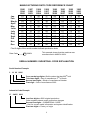
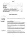
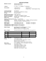
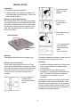
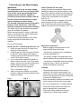
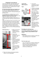
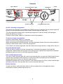
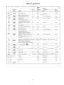
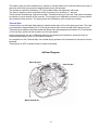
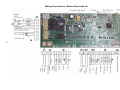
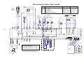
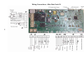
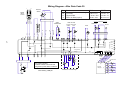
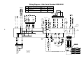
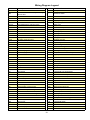
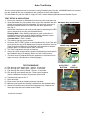
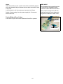
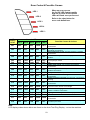
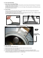
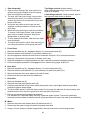
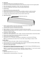
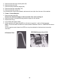
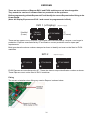
5407170 Issue 6
Aug. 2006
Hotpoint
Aquarius
Washer
Dryers
Models
WD420P
WD420G
WD420T
Commercial
Code
31127
31128
31126
WD440P
WD440G
34189
36234
Service
Information
Indesit Company UK Ltd
© 2006 Reg. Office: Peterborough PE2 9JB. Registered in London: 106725
SAFETY NOTES & GENERAL SERVICING ADVICE
1. This manual is NOT intended as a comprehensive repair/maintenance guide to the appliance.
2. It should ONLY be used by suitably qualified persons having technical competence applicable
product knowledge and suitable tools and test equipment.
3. Servicing of electrical appliances must be undertaken with the appliance disconnected
(unplugged) from the electrical supply.
4. Servicing must be preceded by Earth Continuity and Insulation Resistance checks.
5. Personal safety precautions must be taken to protect against accidents caused by sharp edges
on metal and plastic parts.
6. After servicing the appliance must be rechecked for Electrical Safety. In the case of appliances
which are connected to a water supply (i.e.: Washing Machines, Dishwashers & Food Centres
etc.) checks must be made for leaks from seals gaskets and pipe work and rectification carried
out where necessary.
7. It can be dangerous to attempt 'DIY' repairs / maintenance on complex equipment and the
Company recommends that any problem with the appliance is referred to its own Service
Organisation.
8. Whilst the Company has endeavoured to ensure the accuracy of the data within this publication
they cannot hold themselves responsible for any inconvenience or loss occasioned by any error
within.
2
MANUFACTURING DATE CODE REFERENCE CHART
Jan
Feb
March
April
May
June
July
Aug
Sept
Oct
Nov
Dec
1986
1994
2002
01
02
03
04
05
06
07
08
09
10
11
12
1987
1995
2003
13
14
15
16
17
18
19
20
21
22
23
24
1988
1996
2004
25
26
27
28
29
30
31
32
33
34
35
36
1989
1997
2005
37
38
39
40
41
42
43
44
45
46
47
48
1990
1998
2006
49
50
51
52
53
54
55
56
57
58
59
60
1991
1999
2007
61
62
63
64
65
66
67
68
69
70
71
72
1992
2000
2008
73
74
75
76
77
78
79
80
81
82
83
84
First 2 digits of the serial number indicate production date
Date Code
27 120054
This example shows that the machine was
manufactured in MARCH 2004.
SERIAL NUMBER / INDUSTRIAL CODE EXPLANATION
Serial Number Example
3 10 02 0895
Four remaining digits = Build number that day 895th built
Third two digits = Day of manufacture 2nd of month
Second two digits = Month of manufacture October
First digit = Year of manufacture 2003
Industrial Code Example
37 24455 0010
Last four digits = 0000 original production.
Other numbers denote major production changes
Second five digits = COMMERCIAL CODE*
* Vital for correct model information and system identification
First two digits = Factory of origin
3
1993
2001
2009
85
86
87
88
89
90
91
92
93
94
95
96
INDEX
Safety & Servicing Notes . . . . . . . . . . . . . . . . . . . . . . . . . . . . . . . . . . . . . . . . . . 2
Manufacturing Date Code Chart & Serial Number Information . . . . . . . . . . . 3
Development History . . . . . . . . . . . . . . . . . . . . . . . . . . . . . . . . . . . . . . . . . . . . . 4
Specifications . . . . . . . . . . . . . . . . . . . . . . . . . . . . . . . . . . . . . . . . . . . . . . . . . . . 5
Installation . . . . . . . . . . . . . . . . . . . . . . . . . . . . . . . . . . . . . . . . . . . . . . . . . . 6 - 8
Controls, Options and Wash Programme details . . . . . . . . . . . . . . . . . . 9 - 13
Wiring Details
Wiring Connections & Wiring Diagram - Before D.C. 40 . . . . . . . . . 14 - 15
Wiring Connections & Wiring Diagram - After D.C. 39. . . . . . . . . . . 16 - 17
Wiring Diagram - After Serial Number 60508.0000 . . . . . . . . . . . . . . . . . . 18
Wiring Diagram Legend . . . . . . . . . . . . . . . . . . . . . . . . . . . . . . . . . . . . . . . . . . 19
Auto Test Set Up, Test Sequence, Diagnostics & Error Codes . . . . . . 20 - 23
Dismantling Instructions . . . . . . . . . . . . . . . . . . . . . . . . . . . . . . . . . . . . . 24 - 30
EEProms . . . . . . . . . . . . . . . . . . . . . . . . . . . . . . . . . . . . . . . . . . . . . . . . . . . . . . 31
DEVELOPMENT HISTORY
September 2004
Date Code 33
Aquarius versions WD420 enter full production.
November 2004
Date Code 35
WD440P - General tactical model, same as WD420 but with 1400 rpm spin.
February 2005
Date Code 38
WD440G first produced.
April 2005
Date Code 40
Models WD420 & WD440
Change to Cold Fill and deletion of heater box fluff filter.
On 25th April 2005 (Date Code 40), this range of washer dryers changed from
Hot and Cold Fill to Cold Fill only. Along with this change a modification was
made to the tumble dryer heater box assembly with the introduction of a
straight heating element, this to improve the air flow through the heater box.
This change enables the removal of the heater box fluff filter and deletion of the
flushing valve and hose. The thermistor, one-shot cut out and fan assembly are
not affected. The 4-way valve is replaced by a 3-way valve and the hot supply
hose is deleted.
A new file setting (EEPROM) is used for cold fill machines, but the consumer
programmes remain the same for both Hot and Cold and Cold fill machines.
The changes to the heater box assembly does not effect the EEPROM file
settings.
May 2006
(S/N 60508.0000)
Model WD420 & WD440
Re-introduction of flushing valve style heater box assembly.
On 8 May 2006 (S/N 60508.0000), the flushing valve and fluff filter was
re-introduced in production, along with spiral element, metal fan, externally
mounted dryer motor and thermal fuse cable, which is attached to the heater
box upper casing in place of the one shot cut-out device.
4
SPECIFICATIONS
Models Covered
Colours
Dimensions
WD420 Washer Dryer
WD440 Washer Dryer
P = Polar, G = Graphite, T = Sandstone
Height 850 mm
Depth 600 mm
Width 595 mm
Weight 66 kg. Packed approx 69 kg
Country of Origin
Electrical Supply
Energy
Washing Performance
Energy Consumption
Water Consumption
Wash Load
Washing & Drying Load
Spin Speed
Control PCB
Wash Heater
Dryer Heater
Thermistor NTC - Wash
Thermistor NTC - Dryer
Water Supply
Great Britain
230 Volts AC @ 50Hz Fuse 13amp
Energy Class: B
Class: A @ 40°C
1.02 KWh / Cycle @ 60°C Cotton
Washing Only = 55 Litres @ 60°C Cotton
6 kg Cottons
5.0 kg + 5.0 kg Cottons
WD420 - 1200 rpm maximum WD440 - 1400 rpm maximum
220/230Volt 50/60Hz Type Merloni EVO 2
1800 Watts @ 230 volts
Resistance 30 Ω approx.
1200 Watts @ 230 volts
Resistance 43 Ω approx.
Resistance: 20 KΩ @ 20°C
Resistance: 26 KΩ @ 20°C
Hot & Cold Valves - Coil Resistance 3.8 KΩ
Max Pressure = 1 Mpa (10bar)
Minimum Pressure = 0.05 Mpa (0.5bar)
Motor - Wash
Universal Series Wound 230V 50Hz AC with tapped field
Pins
Resistances
FHP
CESET
5-6
Armature Varies with brush-gear
1.5 Ω ± 8%
1.78 Ω ± 7%
3-4
Full Field
1.26 Ω ± 8%
1.25 Ω ± 7%
3-7
Tapped Field
0.47 Ω ± 10%
0.41 Ω ± 7%
1-2
Tacho 16 Pole (8 pairs)
135 Ω ± 10%
68.7 Ω ± 7%
Motor - Dryer Fan
Pump
Door Lock
Torque Settings
230 Volt 50 Hz Resistance approx. 45 Ω
2 Pole Synchronous
220 / 240 Volt 25 Watt, Resistance = 165 Ω
Maximum Head 1.4 metres
Flow rate @ 0.9 metres / 30 Litres per minute
P.T.C. Bimetallic - Time Delay approx 2 minutes
Outer Drum = 8Nm
Upper Balance Weight = 18 Nm
Lower Balance Weight = 24 Nm
Heater Box to Drum = 12Nm
Heater Box Top to Bottom = 8Nm
5
INSTALLATION
Unpacking
1. Unpack the washing machine.
2. Unscrew the bolt
using a 13 mm
spanner.
2. Check whether the washing machine has
been damaged during transport. If this is the
case, do not install it.
Remove the polystyrene base
The vertical block part of the base (see below)
should have stayed intact when the base was
removed. If it has broken off and is still inside
the machine, carefully lay the machine on its
side, onto the polystyrene top cap and then
remove the block.
3. STOP when 3
threads can be
seen.
4. Hold, slide and pull
to remove.
Vertical block
! It is important the
transit bolt and
spacer come out
intact
(see image left).
polystyrene
base
Warning:
Packaging materials are not childrens toys.
Remove the transit fixings
Follow these instructions to remove the TWO
transit fixings. IMPORTANT: Situated one either
side of the rear panel, both transit bolts (complete
with spacers) MUST be removed before use.
Failure to do so may cause damage to the
machine!
1. Use a crosshead
screwdriver to
remove the plastic
cover.
For safety, replace both plastic covers over the
holes left by removing the two bolts.
Levelling
1. Install the washing machine on a flat sturdy
floor, without resting it up against walls,
cabinets etc.
2. Compensate for any unevenness by
tightening or loosening the adjustable front
feet. The angle of inclination, measured
according to the worktop must not
exceed 2°.
Levelling the appliance correctly will provide it
with stability and avoid any vibrations, noise
and shifting during operation. If it is placed on
a fitted or loose carpet, adjust the feet in such
a way as to allow enough room for ventilation
beneath the washing machine.
6
Connecting to the Water Supply
WARNINGS:
The temperature of the hot water supply
should ideally be 60°C and no higher than
70°C as this could cause damage to the
laundry and the machine. Applies to
products produced prior to Date Code 40.
Do not connect the machine to a single
outlet instantaneous water heater.
The hot and cold water pressure should be
between 3 and 150 psi (21 - 1034 kPa).
Incorrect pressures could lead to flooding.
The water supply taps should be accessible
when the machine is installed.
Before connecting the fill hoses, check that
water is running from the water supply taps
you will use for the machine.
Connect the washing machine to the water
supply using the fill hoses fitted to the
machine.
Do not use old hoses.
Hot & Cold Fill - Cold fill only from D.C. 40
1 Unclip the grey and blue fill hoses from
the back of the machine.
2
3
4
If the fill hoses are too short:
Longer fill hoses are available. Remove the
existing fill hoses from the inlet valves on the
back of the machine and fit the new longer fill
hoses as shown above with the angled ends
of the hoses connected to the machine
(see Fig. 2).
If no hot water supply is available or the hot
water pressure is low, a cold fill adaptor
(Fig. 3) and fitting instructions are available.
Applies to products produced prior to D.C. 40.
Electrical connections
Before plugging the appliance into the
mains socket, make sure that:
- the socket is earthed and in compliance
with the applicable law.
Connect the free end of the grey fill hose
to the HOT water supply (see figure1).
Connect the free end of the blue fill hose
to the COLD water supply.
Turn on the water supply and check for
leaks. If there is a leak, turn off the water
supply, remove the connector and check
that the sealing washer is in place.
- the supply voltage is included within the
values indicated in the Specifications page.
- the socket is compatible with the washing
machines plug. If this is not the case,
replace the socket or the plug.
Refit the connector and tighten it.
Location
Turn on the water supply.
When moving the machine into its final
position, make sure that the hoses are not
trapped or kinked.
! The washing machine should not be
installed in an outdoor environment, not
even when the area is sheltered, because it
may be very dangerous to leave it exposed
to rain and thunderstorms.
Fig. 1
Fig. 2
! When the washing machine is installed, the
mains socket must be within easy reach.
! Do not use extensions or multiple sockets.
! The power supply cable must never be
bent or dangerously compressed.
! The power supply cable must only be
replaced by an authorised engineer.
7
Drainage Connections
Under Sink
Waste System
Take care when you remove the drain hose
from the clips on the back of the machine.
All machines are tested with water before they
leave the factory so a small amount of water
may still be in the hose.
Do not remove the hooked end support from
the GREY drainage hose when using any of
the drainage methods detailed below. You
may need to reposition it as required along the
drainage hose.
For drainage into a standard work top sink,
ensure the outlet pipe has a minimum
diameter of 32 mm. If the sink is inset, the front
edge of the basin must be less than
75 mm from the front edge of the worktop, so
that the drain hose will hook securely into the
sink.
Unclip the drainage hose from the back of the
machine and hook over into the sink. Make
sure that the sink is free of any obstructions
and that the sink plug can not fall into the sink,
preventing the water from draining away
freely. Pumped out water may be very hot.
We recommend one of the following drainage
methods:
Stand pipe Fig. 1
1 Make sure that the
standpipe has a
minimum diameter
of 38 mm.
2 Remove the
drainage hose from
the clips on the
back of the
machine.
3 Make sure that the
500 mm
top of the standpipe
is positioned at
least 500 mm from
the floor (see
Fig.1).
Fig.2
1 Cut out the
membrane, bung or
blanking plug (see
Fig. 2).
2 Unclip the drainage
hose from the back
of the machine.
cut
off
end
3 Move the hooked
end support along
the drainage hose
as required.
4 Attach the drainage
hose securely to
the under sink
drainage unit, using
a hose clip (see
Fig. 3).
Fig.3
Hose clip
5 Raise the hooked
end support up to at
least 800 mm to
avoid water being
drawn back into the
machine.
Extending the drainage hose
If the GREY drainage hose is too short, a
longer drainage hose is available from our
Genuine Parts & Accessories Mail Order
Hotline.
WARNING!
The company denies all liability if and when
these warnings are not respected.
The first wash cycle
Once the appliance has been installed and
before you use it for the first time, run a
wash cycle without detergent and no
laundry, setting the 90°C programme
without a pre-wash cycle.
Use the plumbing
indicator line label
on the back of the
machine as a
guide.
4 Place the drainage hose approximately
100 mm into the standpipe.
8
Controls
Option Buttons
Progress Indicator Lights
Variable Control(s)
Start/Cancel
On/Off
Programme Selector Dial
On-Off / Selecting a programme
The machine is switched on by pressing the 'On/Off' button for 2 seconds. All the indicator lights will
light up for a few seconds and the 'Door Locked' indicator light will flash once.
Turn the programme selector dial to the desired programme. Load the laundry and detergent.
Select the options you require.
Press the 'Start/Cancel' button for 2 seconds to start the programme.
To stop or change a programme
Press the 'Start/Cancel' button for 2 seconds.
Select 'Pump Out' on the programme selector dial.
When the machine has finished emptying, turn the programme selector dial to the new programme.
Press the 'Start/Cancel' button to start the programme.
If you cancel a hot wash programme, take care when removing the laundry, it might still be very hot.
Progress indicator lights
These will light up when you choose a programme, to indicate the progress of the selected
programme. When started, the first light in the cycle will stay lit and as the programme progresses,
successive lights will come on until the programme finishes.
Door Locked indicator light
The ‘Door Locked’ indicator light will come on two seconds after you press the 'Start/Cancel' button
and will stay lit throughout the programme. A short time after the programme has finished the
indicator light will go out and you can then open the door.
Selected programmes will not start if the door is not closed properly, the 'Door Locked' indicator light
will flash to show this. Push the door shut until you hear the catch click.
Button Selection:
To select an option, press the button and you will see a light come on alongside the button.
Press again to cancel, and the light will go out.
9
Options
Option Buttons
Progress Indicator Lights
Variable Control(s)
Start/Cancel
On/Off
Programme Selector Dial
Options are selected by pressing the button and confirmed by illumination of the LED.
Drying High Heat
The default setting is LOW heat. By selecting this allows HIGH heat for tumble drying.
Reduced Creases
Changes wash action and slightly increases drum speed on cotton programmes and removes end
of wash spin with a reduced speed on final spin on synthetic programmes.
Available on programmes C, E, G and Rinse and Spin programmes
Rinse Hold
Clothes will be suspended in cold water at the end of the final rinse. To complete the programme,
press the button when the LED is flashing
This option is not available on programmes A, H, K, L and Spin only
Time Saver
Saves programme time by up to a third depending on programme selected and is achieved by
reducing wash run times.
This option is only available on programmes B, D, G and H.
Extra Rinse
Adds an extra rinse to the programme
This option is not available on programmes A, E, H, J, K, L or Spin only
Variable Wash Temperature Control - Selected by Rotary Knob
Enables a lower wash temperature and No Heat to be selected
Note; if the dial is left at the maximum temperature setting the programme will be washed at the
maximum temperature for the programme selected
Variable Tumble Drying Time - Selected by Rotary Knob
Enables the required drying time to be chosen.
Maximum 180 minutes plus 20 minutes Cool Tumble.
10
Wash Programmes
11
Controls Information
A single control board located at the back of the machine contains all the circuitry to control the
machine and interfaces with the programme selector, option buttons and LEDs located on the
console panel. The control board has an access port to the rear of the machine to enable
programming and diagnostic checks to be carried out.
Programmes are selected by turning the rotary switch to one of the 16 positions a rotary switch.
Special options can be selected by pressing the appropriate buttons and the programme process
followed by LEDs.
The machine is switched on using the On/Off button and selected programmes started by pressing
the Start/Cancel button.
Automatic Features
Auto Half Load
Auto half load adjusts the amount of water in the wash load depending on the absorbency of
garments in the wash load.
Fabric Conditioner Dispensing
Dispensing of fabric conditioner is achieved by energising both the Pre-Wash and Main Wash cold
valves.
Out of Balance Protection
The machine has an inbuilt feature to prevent spinning with an unbalanced load. A calculation via the
motor tacho and control board detects the current drawn by the motor during distribution.
Before each spin, the controls senses the load within the drum and if the load is calculated to be out
of balance the machine will not automatically spin to the full speed.
There are two levels of out of balance, level 1 @ 480 grams and level 2 @ 1030 grams.
If the out of balance is below level 1 the machine will spin at full speed, if between level 1 and level
2 the machine will spin at the reduced speed of 600 rpm and above level 2 spin at reduced speed of
400 rpm. There are 15 attempts at level 1 with 57 attempts in total, this being the same for both cotton
and synthetic spins.
The wool spin has one level of out of balance @ 1.8 kg. The controls will make three attempts to
achieve a balance, if after three attempts a balance is not achieved; the spin is reduced to a speed
of 90 rpm.
The Condenser Tumble Drying Process
The drying process is by means of a closed air system driven by a circulating fan. Air is drawn
internally from the rear of the outer drum, passed over a heating element and returned to the front of
the drum via an inlet through the door seal. The warm air travels through the wash load collecting
moisture, the moist air then condenses on a stream of cold water running down the inner rear section
of the outer drum. The relatively dry air is then drawn back over the element to repeat the process.
The circulating fan, one shot cut-out or thermal fuse cable along with a thermistor to control the air
temperature are located in a heater box assembly attached to the top of the outer drum.
The airflow passes through a filter located within the air duct from the outer drum to the heater box
assembly. At the start of every drying program the filter is automatically cleaned by flushing water
through it by means of a fill valve wired in parallel with the hot fill valve for 5 seconds duration.
On products produced from April 2005, Date Code 40, the filter flushing hose was deleted.
On products produced from May 2006 (S/N 60508.0000) the flushing valve system was
re-introduced, but now controlled by the Eeprom using a separate valve located next to the fill valve.
See Notes on page 4.
12
The water supply for the condenser is by means of a direct feed from a cold inlet valve to the rear of
the outer drum and is pumped out approximately every 30 seconds.
The closed air system is sealed by a 'P' trap located within the dispenser inlet hose.
The hose is topped up with cold water every 8 minutes for a duration of 1 second.
There are two heat settings, high and low heat. The default setting is low heat, High Heat is selected
by means of a push button on the console. The drying time is selected by means of a rotary switch
also located on the console. The drying times are followed by a 20 minute cool tumble.
Thermal Spin
A thermal spin on the High Heat setting is carried at the start of the of the drying process. The load
is pre-heated to approximately 50°C by the dryer heater with normal tumble action and pump out.
The thermistor located in the wash heater will sense the load temperature and when 50°C is achieved
a 5 minute Spin profile will be carried out at full spin speed.
During thermal spin the out of Balance detection will operate and maximum speed will only be
achieved depending on the out of balance condition.
On completion of the Thermal Spin, the tumble drying process will commence for the period of time
selected.
Thermal spin is NOT available when low heat is selected.
Airflow Diagram
Warm Dry Air
Cold Dry Air
Warm Humid Air
13
Wiring Connections - Before Date Code 40
14
Wiring Diagram - Before Date Code 40
N
L
Pressure
Switch
Pins
5-6
3-4
3-7
1-2
16
11
MAINS
INPUT
FILTER
1
14
12
2
1
3
1
3
R
R
MOTOR
WASH VALVES
WASH
THERMISTOR
R
FHP
CESET
1.5 Ω ± 8%
1.78 Ω ± 7%
1.26 Ω ± 8%
1.25 Ω ± 7%
0.47 Ω ± 10% 0.41 Ω ± 7%
135 Ω ± 10%
68.7 Ω ± 7%
4
1
2
Resistances
Armature Varies with brush-gear
Full Field
Tapped Field
Tacho 16 Pole (8 pairs)
Cold
Filter Pre-Wash Main Wash
COLD
FABRIC
HOT
ARMATURE
PUMP
1
4
1
2
Lav.
2
*
1
L
C
2
3
2
2
2
5
6
4
7
3
2 1
7
6
5
4
3
2 1
j9
9
7
j3
6
4
1
3
1A
10w
EVP
1
10w
EVL
2
1
2
j8
9
8
j7
j15
1
SDA
TEST CONNECTOR
15
NC
j1
1
P
12 11
j5
2
10w
2
1
EVC
3
1A
OVERFLOW
4
10A
10A
FULL
5
COMMON
8A
10A
6
EMPTY
2
RR
1
10A
12A
12A
2
GND
RX
1
T
M
1
1
TACHO
5
1
GND
5
4
3
2
1
5
4
3
2
1
SCL
Vcc
Test
5
RTN_PORTA
RTN_IP
j2
7
2
Note: COLD VALVES
Pre-Wash & Wash Valves are both
energised to provide fabric conditioner.
wd420 monophase wiringdiagram.ai
4
1
1
A
2
3
4
Connector TAB
5
3
j15
3
2
3
R D CL A cc
VN GN S SD V
Asc.
PCB with
LED lights
Condenser Tumble Dryer
3
2
3
j11
1
3
4
1
j14 2
8
1
1
5
6
j17
4
4
4
j12
1
5
3
3
2
6
2
2
10w
1
1
1
D
C
10A
j13
j10
48w
j4
3
Í
1
3
Í
1
3
Í
1
3
1
M1
3
1
M2
3
1
M3
Wiring Connections - After Date Code 39
16
Wiring Diagram - After Date Code 39
N
L
Pressure
Switch
Pins
5-6
3-4
3-7
1-2
16
11
MAINS
INPUT
FILTER
1
14
12
2
1
3
1
3
Resistances
Armature Varies with brush-gear
Full Field
Tapped Field
Tacho 16 Pole (8 pairs)
FHP
CESET
1.5 Ω ± 8%
1.78 Ω ± 7%
1.26 Ω ± 8%
1.25 Ω ± 7%
0.47 Ω ± 10% 0.41 Ω ± 7%
135 Ω ± 10%
68.7 Ω ± 7%
4
MOTOR
1
2
WASH VALVES
WASH
THERMISTOR
R
ARMATURE
Pre-Wash Main Wash
COLD
FABRIC
R
R
PUMP
4
1
NC
j1
2
2
5
6
4
7
3
2 1
7
6
5
4
3
2 1
j9
2
1
12 11
j5
L
9
7
j3
6
4
1
3
1A
10A
2
2
Lav.
1
2
*
3
2
1
P
10w
EVL
3
1
10w
EVP
4
1A
OVERFLOW
5
COMMON
10A
FULL
8A
10A
6
EMPTY
2
RR
10A
12A
12A
1
GND
RX
2
T
M
1
1
TACHO
5
1
1
2
j8
9
8
j7
1
SDA
TEST CONNECTOR
17
j15
GND
5
4
3
2
1
5
4
3
2
1
SCL
Vcc
Test
5
RTN_PORTA
RTN_IP
j2
7
2
1
Note: COLD VALVES
Pre-Wash & Wash Valves are both
energised to provide fabric conditioner.
5407170wd2_coldfill.pdf
4
1
A
2
3
4
Connector TAB
5
3
j15
3
2
3
R D CL A cc
VN GN S SD V
Asc.
PCB with
LED lights
Condenser Tumble Dryer
3
2
3
j11
1
3
4
1
j14 2
8
1
1
5
6
j17
4
4
4
j12
1
5
3
3
2
6
2
2
10w
1
1
1
D
C
10A
j13
j10
48w
j4
3
Í
1
3
Í
1
3
Í
1
3
1
M1
3
1
M2
3
1
M3
Wiring Diagram - After Serial Number 60508.0000
Mains Input
Filter
N
L
Pins
5-6
3-4
Resistances
Armature - varies with brush gear
Full Field
FHP
1.57+/- 8%
1.267 +/- 8%
CESET
1.787 +/- 7%
1.257 +/- 7%
3-7
Tapped Field
0.477 +/- 10%
0.417 +/- 7%
1-2
Tacho 16 Pole (8 pairs)
1357 +/- 10%
68.77 +/- 7%
11
16
Pressure
Switch
Motor
Stat.
Armature
4
1
TF
6 7
L
7
6
5
4
3
2
1
8
7
6
PIENO
10w
4
EVL
10w
2
1
3
5
4
3
2
1
1
10A
*
2
2
2
2
1
Feedback
RR
2
2
EVP
12A
12A
1
10A
?A
2
1A
P
?A
C
OVERFLOWW
4
1
R
1
?A
3
1
Pump
7
6
5
Main
Wash
?A
6a
2
Pre
Wash
Lav.
GND
5
4
COMUNE
3
Wash
Thermistor
6a
2
6a
Stat.CP
T
Stat.CI
6a
1
RX
3
?A
6a
TG
SEN.COND
Tacho
1
M
1
2
1
5
1
14
Wash Valves
1
4
1
12
2
18
SDA
1
Test
Connector
SCL
j7
GND
Vcc
Test
5
UI
RA
10A
3
3
1
1
4
6
7
1
3
4
3
2
5
4
3
2
1
5. 4
3
2
1
1
8
10w
2
10A
Feedback
2
1
1
48w
2
10w
1
5
Asc.
1
j11
1
3
C
3
Flushing Condenser
Valves
3
Connector TAB
3
2
1
2
Vcc
R
A
3
4
5
1
R
SCL
2
SDA
3
GND
j17
4
PCB with
LED lights
3
Í
1
3
Í
1
Condenser Tumble Dryer
5
4
5407170wd3.ai
WD420/440
24000105900
3
2
j15
6
4
A
VNR
TF
3
Í
1
3
1
3
1
M1
M2
3
1
M3
Wiring Diagram Legend
AQS
Aquastop solenoid valve
N
Neutral or Terminal board
B
Buzzer or Door lock
NC
No spin
BF
Terminal board contacts, dryer heating
element and
P
Pressure switch
BP
Door lock
P1
Pressure switch 1st level
C
Condenser
P2
Pressure switch 2nd level
AC
Condenser
PA
High speed potentiometer
DV
Switch
PB
Low speed potentiometer
EF/CL
Cold water/bleach solenoid valve
PL
Pure wool
EF/L
Cold water/wash solenoid valve
PM
Motor thermoprotector
EF/P
Cold water/prewash solenoid valve
PR
Timer programmer or Pressure switch
ER
Cut-out heater
PS
Drain pump
ET
Cut-out thermostat
R
Heating element
EV
Solenoid valve
Ras/RA
Drying heater
EVA
Drying solenoid valve
RE
Relay
EVC
Hot water solenoid valve
RR
Heating element
EVF
Cold water solenoid valve
RV
Speed regulator
EVL
Wash solenoid valve
S
Indicator light
EVP
Prewash solenoid valve
SL
Line indicator light
FA
Noise filter
SO
Door indicator light
FD
Delicate drying thermostat
SR
Heating indicator light
FE
Intense drying thermostat
ST
Temperature selector or Stop with water
FRT
Thermofuse resistance
SV
Spin speed selector
I
Reverser
T
Timer contacts
I1..I2..3.
Switches/deviators
TA
Drying timer contacts
IA
On/Off switch
TB
Low temperature thermostat
IC
Switch NC / 1/2 load
TC
Crosspiece earth
ID
No spin switch
TFL
Flange earth
IE
Water-economizer or NC Switch
TG
Main earth
IF
Spin decrease switch
TH
Thermostat
IP
Door switch
TH1
Thermostat 1st temperature
IR
Line switch
TH2
Thermostat 2nd temperature
IS
Water-stop
TH3
Thermostat 3rd temperature
L
Line or Lamp
THF
Work thermostat
LB
Low level
THR
Adjustable thermostat
LN
Normal level
TM
Motor earth
LS
Indicator light
TMB
Base cabinet earth
M
Earth symbol or Dryer motor
TMP
Motor thermoprotector
MC
Spin motor or Spin winding
TMS
Thermostop
MI
Induction motor
TP
Thermoprotector or Pump earth
ML
Wash motor or Wash winding
TPS
Drain pump earth
MO
Terminal board
TR
Heating element earth
MP
Door microswitch
TS
Safety thermostat or Support earth
MR
Microdelay device
TT
Timer earth
MT
Timer motor
TTH
Thermostat earth
MV
Fan
TV
Tub earth
MV - Ras
Dryer fan (RA)
ZBN
Timer
Mzbn/M
zbn timer motor
19
Auto Test Setup
An error test programme can be carried out using Hardware Key Part No. C00095669 which is inserted
into the socket at the rear of appliance and connects to the Power Module.
The Hardware Key can be used on Vogue 4 EVO 2 model Washing Machines and Washer Dryers.
TEST SETUP & INDICATIONS
1. Ensure the machine is switched off and remove the serial port cap.
2. Insert Hardware Key into socket at the rear of the machine with the Hardware Key shown fitted
plastic pin protection tab fully extended. If it has been removed it
should be refitted before use. Refit Tab with latch uppermost.
See Fig. 2.
Switch the machine on and verify model type by observing the LED
colour displayed on the key as indicated below:Flashing Red = Slow flashing indicates a good connection of
Hardware Key into the module. Rapid flashing indicates a poor
connection. If this isn’t displayed it will not work.
Constant Blue = EVO 2 model.
Fig. 1
3. The selector can be in any position.
4. Press the AUTO TEST button on the Hardware Key. 'Auto Test' will
Pin protection Tab
scroll across the key LCD display and a beep is heard from the key.
shown
fully extended
If the Programme Selector is motorised it will advance to another
position after a 10 second pause (this is normal).
TAB
5. The Test Programme will now commence.
LATCH
6. If there is a fault on the machine it will be indicated by a fault code in
the Hardware Key LCD display. Refer to Fault Codes section.
7. The fault must be cleared before the appliance or self test will run
again correctly. (See Notes on following page.)
Fig. 2
TEST SEQUENCE
a)
b)
c)
d)
Fills through main wash valve - approx. 10 seconds.
Fills through pre - wash valve - approx. 10 seconds.
Fills through hot valve (if fitted) - approx. 10 seconds.
Fills through main wash and pre - wash valves together
(fabric conditioner function) to pressure switch level.
e)
f)
g)
h)
i)
Tumbles and heats to 30 °C
Drain and spin.
Dryer motor and dryer heating element activated.
Machine now resets and a beep is heard from the Hardware Key.
Switch off machine and remove the Hardware Key. Replace the
serial port cap and secure with screw if fitted.
continued overleaf ...
20
AUTO TEST
BUTTON
LCD
DISPLAY
Notes:
When first starting a test, a fault code could immediately appear
since the Hardware Key will detect the last fault the machine had
in the past.
USB CABLE
In this situation it will be necessary to proceed as follows:
This is used in conjunction with the
Washing Machine Doctor diagnostic
programme installed on EMIT units.
Switch off and unplug from the power supply for 30 seconds
and re-start test.
This Hardware Key is supplied as part
of a kit (Part No. 5600260) which
includes a USB to RS232 serial cable.
Faults Without Error Codes
If the motor is open circuit the machine will not fill or operate.
RS232
Connector
USB CABLE
21
EEPROMS & DIAGNOSTICS
Three variations of Eeprom can be found or used on Power Boards:
1.
Production Power Boards have a soldered Eeprom and is not replaceable.
2.
3.
Service Power Boards have a socket and the Eeprom is a separate part.
Blank Eeproms.
All types can be programmed or re-programmed via Emit, using a USB lead, Hardware Key and the
relevant Eeprom Writer software. Certain models which have a combined Power and Display board
also require an Adapter fitted between the Hardware Key and the Power Board.
Information can be found in Service Manual 5407177 and Quick Guide 5407200.
The Main Components are shown below.
Fig. A
Fig. A C00115587 Hardware Key
Fig. B C00116135 Low End Adapter
Fig. C 5600261 USB Cable
A Hardware Key Pin Repair Kit is also available which contains five pins. Part Number C00114723.
DIAGNOSTICS
Two versions of a diagnostic programme are available to use after an Eeprom has been replaced or
programmed and for general fault finding. Connection to the appliance is the same as for Eeprom
Writer.
1.
Washing Machine Doctor 1 for Evo 1 based appliances.
2.
Washing Machine Doctor 2 for Evo 2 based appliances.
Information can be found in Service Manuals 5407180 and 5407182 respectively.
Note: This version of the Hardware Key, Eeprom Writer and Washing Machine Doctor
programmes are only available to Indesit Company Engineers.
Pre-programmed Eeproms and Service socket boards are available for repairs and Spare
Parts.
22
Error Codes & Possible Causes
When an error occurs,
the On/Off LED flashes rapidly
and one or more of the Option
LEDs will flash once per second
LED 1
LED 2
Refer to the chart below for
error code definitions.
LED 3
LED 4
LED 5 -
LCD
Display
Code
Console LEDs
LED 1 LED 2 LED 3 LED 4 LED 5
F01
OFF
OFF
OFF
Flash
OFF
F02
OFF
OFF
Flash
OFF
OFF
F03
OFF
OFF
Flash
Flash
OFF
F04
OFF
Flash
OFF
OFF
OFF
F05
OFF
Flash
OFF
Flash
OFF
F06
OFF
Flash
Flash
OFF
OFF
F07
OFF
Flash
Flash
Flash
OFF
F08
Flash
OFF
OFF
OFF
OFF
F09
Flash
OFF
OFF
Flash
OFF
F10
Flash
OFF
Flash
OFF
OFF
F11
Flash
OFF
Flash
Flash
OFF
F12
Flash
Flash
OFF
OFF
OFF
F13
Flash
Flash
OFF
Flash
OFF
F14
Flash
Flash
Flash
OFF
OFF
F15
F16
Flash
OFF
Flash
OFF
Flash
OFF
Flash
OFF
OFF
Flash
F17
OFF
OFF
OFF
Flash
Flash
F18
OFF
OFF
ON
OFF
OFF
Possible Causes & Actions
Motor triac short circuit: check motor & module
connections
Motor jammed / tacho detached: check motor
& module connections
NTC short/open circuit: check thermistor & module
connections
Pressure switch jammed on empty: check switch &
module
Pressure switch jammed on full or pump blocked:
check pump & switch
N/A
Heater relay stuck: check heater and module
connections
Heater relay stuck: check pressure switch, heater &
module connections
Setup error: check eeprom
Pressure switch not sensing: check switch & module
connections
Pump cannot be activated: check pump, connections
& wiring
No communication between cards: check module
connections
High Temperature Rise in Drying: Reduced airflow,
check fan motor & filter for blockage.
No Heat when Drying: Check one shot thermostat,
heater & module connections
Drying Heater Relay Fault: Possibly open circuit.
N/A
Door lock error: check door, door lock & module
connections
Fault on Control Board: Check for damaged EEprom
and Microprocessor
Note:
LCD display codes shown below are found on the Auto Test Plug Display - not on the machine.
23
Dismantling Instructions
Safety Notes
1. Ensure that the appliance is disconnected from the electrical supply before dismantling.
2. Beware of sharp edges on metal panels, plastic mouldings, and pressed parts.
3. Some fixings (especially those into plastic) must be tightened to the correct specification
using a suitable torque wrench.
4. Insulation resistance tests must be carried out with the pressure switch set to ensure that
the water heater is 'in-circuit' during the test.
A Table Top
1. Remove the two screws at the top rear of cabinet.
2. Slide the table top backwards to disengage the location fixings at the rear and lift off.
B Lower Rear Access Panel
1. Remove three screws from the lower rear access panel.
2. Pull the top edge of the panel out and disengage it from its location fixings along the bottom.
C Dispenser Drawer
1. Open the dispenser drawer fully.
2. Press release latch in centre of drawer and pull drawer body and pull drawer away from console.
D Console Panel
1. Remove the table top (A) and dispenser drawer (C).
2. Remove two top screws securing console to cabinet and two screws securing console to
dispenser.
3. Unplug wiring from console PCB - taking note of position.
4. Slide dispenser back.
5. Unclip two plastic lugs securing console panel to front panel and lift clear.
6. Avoid unclipping and handling the control board unless absolutely necessary, as the control
board is susceptible to static electricity.
E
1.
2.
3.
Console PCB and Button Assemblies
Remove the console panel (D).
Remove wiring plug - taking note of position.
Remove three securing clips and lift away from the console.
F(a) Pressure Switch
1. Remove the table top (A).
2. Disconnect the wiring connection block and pressure hose.
3. Carefully unclip bracket from cabinet side and then unclip switch from bracket.
F(b) Front Panel
1. Remove the table top (A), dispenser drawer (C) and console panel.
2. Remove the door seal restraint (G) and door interlock (H).
3. Grip the appliance kickstrip at both ends and pull it off in a forward direction.
4. Remove 4 front panel fixing screws (2 bottom, 2 top).
5. Slide the dispenser housing backwards so that it clears the console backplate opening.
6. Lift the front panel upwards to disengage the four cabinet fixing pegs and lift off.
24
G Door Seal & Restraint:
1. Door Seal to Front Panel Fixing
The door seal is fixed to the cabinet front panel by a wire clamp and a small spring. The spring is
normally at the bottom of the door.
Carefully place a small screwdriver into one of the lugs of the spring and by stretching the spring
the wire band can be removed.
2. Drum Fixing
The door seal is fixed to the drum with a zipper retainer. After removing the front panel (Fb)
remove the zipper as shown in Fig. 3 below.
On refitting place the strap around the door seal and tighten as shown in Fig. 4. Observe correct
seal and zipper fixing positions as shown in Fig. 5.
Fig. 3
Fig. 4
Seal to Drum fixing position
Fig.5
Correct Seal
& Zipper fixing
position
H
1.
2.
3.
4.
5.
Door Interlock
Remove the door seal restraint (G).
Peel the door seal off the front panel, and fold it back into the inner drum.
Remove two screws from the interlock.
The interlock can now be eased out, allowing access to the wiring connection block.
Care must be taken to ensure the correct orientation of the wiring connection plug to prevent
seriously damaging the interlock and / or control board.
25
I Door Assembly
1. Open the door through 180° and remove four
screws securing the hinges to the front panel.
Ease the hinges from the panel.
2. The door trims can now be split. Lay the door
assembly face down on a suitably protected
surface and remove 6 screws securing the two
halves of the door.
3. Unclip the two halves at the hinge end and
separate a sufficient distance to slide out the
door glass.
4. When removing the hinges, note the orientation.
To remove, fold hinges inward, slide towards
each other to release other end. See photo.
Reassemble in reverse order.
5. To fully separate the halves, slide the front away
from the handle.
6. To remove the handle or latch, slide securing pin
out noting the position of the spring and latch.
Top Hinge removal (shown below) Slide towards lower hinge, twist to the left and
slide up to release.
Lower Hinge removal - Slide upwards, twist to
the right and slide down to release.
J
1.
2.
3.
4.
5.
6.
Front Panel
Remove the table top (A), dispenser drawer (C) and console panel (D).
Remove the door seal restraint (G) and door interlock (H).
Grip the appliance kickstrip at both ends tilt forwards, and pull it off in a forward direction.
Remove 4 front panel fixing screws (2 bottom and 2 top).
Slide the dispenser housing backwards so that it clears the console backplate opening.
Lift the front panel upwards to disengage the four cabinet fixing pegs, and lift off.
K
1.
2.
3.
4.
Door Seal
Remove the table top (A), dispenser drawer (C) and console panel (D).
Remove the door seal restraint (G), door Interlock (H) and front panel (Fb).
Remove the drum door seal restraint (G) and lift clear.
Disconnect the door seal from the heater box.
L
1.
2.
3.
Drive Belt
Remove the table top (A).
Remove the lower rear access panel (B).
Carefully peel the belt off the motor pulley taking care not to trap fingers and using suitable
protection against sharp edges.
4. To refit the belt, place it round the motor pulley first, tie-wrap the belt onto the drum pulley, and
rotate the drum from the door aperture to move the belt into position.
5. Ensure any remaining tie-wraps are removed.
It is essential for continued safety that only a genuine spare is fitted. The belt is electrically
conductive and provides an electrical earth to prevent static built up on the inner drum assembly.
M
1.
2.
3.
Motor
Remove the lower rear access panel (B) and drive belt (L).
Disconnect the motor wiring connection plug and earth wire.
Using a 13 mm socket or ratchet ring spanner, remove both motor mount fixing screws.
26
4. Ease the motor off the drum mountings.
5. Prior to refitting the motor, ensure that the drip shield and mounting-bush are not worn or
damaged.
N(a) Lower Balance Weight
1. Remove the table top (A), dispenser drawer (C) and console panel (D).
2. Remove the door seal restraint (G), door Interlock (H) and front panel (Fb).
3. Using a 13 mm socket or spanner, remove three balance weight fixing screws.
4. Pull the weight forward off its mounting lugs.
5. When refitting the balance weight it is essential to ensure that the thread forming screws are
tightened to 24Nm (using a suitable torque-wrench) and that the screws find their original
threads, otherwise the thread can be stripped from the plastic drum lug.
N(b) Top Balance Weight
1. Remove the table top (A).
2. Using a 13mm socket or spanner, remove three balance weight fixings screws.
3. Lift the weight off the drum mountings.
4. When refitting the balance weight it is essential to ensure that the thread forming screws are
tightened to 18Nm (using a suitable torque-wrench) and that the screws find their original
threads, otherwise the thread can be stripped from the plastic drum lug.
P
1.
2.
3.
Heater / Thermistor
Remove the rear lower access panel (B).
Remove the heater wiring and detach the thermistor plug.
Slacken off the 10 mm heater fixing nut and withdraw the heater from the drum.
Q
1.
2.
3.
4.
5.
Drum Pulley
Remove the rear lower access panel (B).
Carefully peel the belt off the motor pulley taking care not to trap fingers.
Using a 13mm socket or spanner, remove the fixing bolt in the centre of the pulley.
Pull the pulley off the drum shaft.
To ensure adequate pulley security always fit the correct pulley bolt (high tensile with dog-point).
If refitting the original bolt apply an engineering Nutlock (Part No. 981009) to the bolt threads.
R(a) Suspension Damper
1. Remove two suspension clamp fixing screws and unclip the clamp from the chassis.
2. Remove the table top (A), dispenser drawer (C) and console panel (D).
3. Remove the door seal restraint (G), door interlock (H) and front panel (Fb).
4. Remove the lower balance weight (Na) if access is required to the left-hand damper.
5. Unclip any wiring retained within the integral clip on the bottom damper moulding.
6. Remove the plastic peg securing the damper to the outer drum using special tool Part No.
5600198.
7. Withdraw the suspension damper. The unit should not be split and is not serviceable.
8. When reassembling, fit a new plastic peg if the locking-tab on it shows signs of damage.
R(b) Suspension Spring
1. Remove the table top (A).
2. Unclip any wiring retained within the integral clip on the spring bearing keeper plate.
3. Gently lever out the bearing keeper plate with a small flat bladed screwdriver.
4. Unhook the spring from the cabinet top rail bearing.
27
S
1.
2.
3.
4.
Dispenser
Remove the table top (A) and dispenser drawer (C).
Remove two screws around the dispenser recess and two screws from valve support panel.
Ease the dispenser backwards to unclip it from the cabinet top rail.
Remove the dispenser outlet hose, and any harness retention ties.
T
1.
2.
3.
4.
Drain Pump
Remove the lower rear access panel (B).
Detach the sump hose from the pump using a suitable container to catch any water.
Disconnect the drain hose from the pump and unplug the wiring connection block.
Lift plastic the locking tab and slide the pump inwards and lift clear.
U Inner Drum Lifter
3rd hole from the front
1. Insert a small screwdriver onto the 3rd lifter hole from the front of the drum.
This will depress the drum flap securing the lifter.
2. Slide the lifter to the front of the drum and remove.
3. Before refitting, lift the drum locking tab 3 mm above the drum surface.
4. Offer the lifter to the holes in the drum, slide lifter to the back of the drum until a click is heard as
the lifter is locked into place.
V
1
2
3
4
Heater Box / Drum Assembly
Disconnect cable connections to motor, heater, thermistor and thermostat / thermal fuse cable.
Disconnect tie-wrap fixing heater box assembly to the door seal.
Disconnect filter flushing hose (if fitted).
Remove five Torx T30 screws fixing heater box assembly to outer drum and lift away.
Note: On re-assembly fix screws in front to rear order, torque setting for screws 12 Nm.
V (a)Fan Motor
1 Disconnect cables to the motor, heater, thermistor and thermostat.
2 Remove the seven Torx T20 screws holding top and bottom sections and lift top section away.
3 Remove fan from motor shaft by unscrewing 11 mm nut.
Note; this is Left Hand Thread.
4 Remove the four fixing screws and release motor. (From Serial Number 60508.0000 the motor
fixing screws are external to the heater box casing.)
Note: On re-assembly the fan must have a clearance of approximately 2 - 3 mm from the inside
of the top section. Use nutlock 242 (Part No. 981009) on thread of fan nut.
V (b)Heater
1 Remove top section as in V (a) 1 - 2.
2 Release heater by removing the two 19 mm nuts.
28
V (c) One Shot Cut-Out
1 Remove top section as in V (a) 1 - 2.
2 Remove heater as in V (b) 1 - 2.
3 Remove screw holding heat shield to top section.
4 Remove two screws fixing cut-out to top section.
Thermal Fuse Cable - From Serial Number 60508.0000
To remove: Disconnect the thermal fuse from the heater / loom end. Remove the thermal fuse
cable clamp.
W(a) Drum Assembly
1. Remove the table top (A).
2. Remove the top balance weight (Nb).
3. Remove heater box assembly (V).
4. Remove the dispenser drawer (C).
5. Remove the console panel (D).
6. Remove the dispenser (S).
7. Remove the front panel (Fb).
8. Remove the lower balance weight (Na).
9. Remove the lower rear access panel (B).
10. Remove the motor (M).
11. Detach the drum from the damper units by removing the two plastic pegs using special
tool Part No. 5600198.
12. Remove the sump hose fixing clip and detach the sump hose from the sump chamber.
13. Disconnect heater / thermistor wiring and release the wiring harness from the drum clips.
14. Unclip any wiring retained within the integral clip on the spring bearing keeper plates.
15. Gently lever out the spring bearing keeper plates with a small flat bladed screwdriver.
16. Unhook springs from the cabinet top rail bearings.
17. Carefully lift the drum assembly out of the cabinet.
W(b) Inner Drum & Support Assembly / Drum Seal / Outer Drum Halves
1. Remove the drum assembly (Va).
2. Remove the drum pulley (Q).
3. Loosen the inner drum assembly by tapping the drum shaft with a soft copper hammer or by
inserting a pin punch into the shaft hole and tapping with a copper hammer.
4. Remove sixteen T30 Torx head drum fixing screws and detach the drum front.
5. Lift out the inner drum and support assembly.
6. The inner drum and support are not designed to be separated, and must be replaced as an
assembly if required.
7. Always fit a replacement drum seal if the drum has been split and ensure that the seal joint is at
the top. When reassembling the drum halves it is essential to ensure that the thread forming
screws find their original threads, otherwise the thread can be stripped from the plastic drum
lugs. Retighten the drum joint fixing screws to 8Nm (using a suitable torque-wrench).
X
1.
2.
3.
4.
Cabinet
Remove the table top (A).
Remove the dispenser drawer (C) and console panel (D).
Remove the front panel (Fb).
Remove the lower balance weight (Na).
29
5. Remove the lower rear access panel (B).
6. Remove the motor (M).
7. Remove the top balance weight (Nb).
8. Remove the drum assembly (Va).
9. Remove the drain pump (T).
10. Unscrew feet, remove the wheels, and remove hose clips from the rear of the cabinet.
Y Power / Control Module!
1. Remove back panel (B).
Ensure the electrical supply is disconnected. See notes on Page 2.
2. Remove screw or screws securing module support to the cabinet.
3. Disconnect wiring.
4. Lift module and support clear.
5. When replacing the board an EEProm will also be required - refer to following page.
Note: To remove and fit the EEProm use Insulated Tweezers Part No. C00066292 as shown
below.
On the original control board, the EEProm may be soldered to the board and cannot be
removed.
EEPROM Removal from PCB
IC Removal Tool
30
EEPROMS
There are two versions of Eeprom EVO1 and EVO2 and they are not interchangeable.
They match the version of software fitted on production to an appliance.
Before programming a blank Eeprom via E-mit identify the correct Eeprom before fitting to the
Power Board.
(Note: All Display Eeproms are EVO 1 and cannot be programmed via Emit.)
EVO 1 (+ Display)
Fairchild
(F xxxx)
F B34AG
93C86AN
(Equivalent Types)
ST 93C86W6
ST
(ST xxxxx)
There are two types of EVO1 Eeprom. The original one manufactured by Fairchild, is no longer in
production. Eeproms manufactured by ST are used on current production and for spare part
requirements.
Both types have the above numbers stamped on them to identify and must not be fitted to EVO2
machines.
EVO 2
ST 24C64 6
ST 24C64W6
(Equivalent Types)
ST 26C64W6P
EVO2 Eeproms are manufactured by ST. These also have a unique identification number as shown.
These Eeproms must not be fitted to EVO1 machines.
Fitting
The correct orientation when fitting any version Eeprom is shown below:
31
PARTS
and
ACCESSORIES
To order parts and accessories contact our
National Mail Order Parts Hotline
08709 077 077
Monday to Friday 8.00am to 5.30pm
Saturday 8.30am to 12.00 noon
or online at :
www.theservicecentre.co.uk
32