1
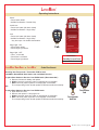
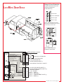
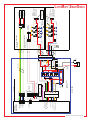
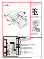
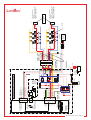
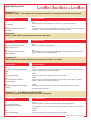
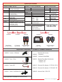
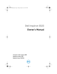
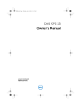
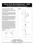
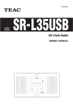
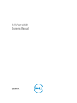
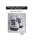
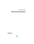
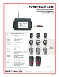
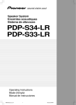
LatchMatic
®
SERVICE MANUAL
for LatchMatic ® and LatchMatic ® Smart Shield ™
LATCHMATIC -SMARTSHIELD
©
HANDS FREE Operating Instructions
Unlock
Truck Cab
• Anytime HotFob enters SmartShield Zone
• Press HotFob Unlock button
• Audible Confirmation: Double Chirp
3 FT
3 FT
Lock ONLY - Any Door Open
Truck Body
5 FT
• Press HotFob Lock button - Doors Lock
• NO Audible Confirmation
5 FT
Lock and Arm
8 FT
8 FT
HotFob
8 FT
Wheel-well
Eddy Field
SmartShield Zone
**Eddy Field range may
vary +/- 10% based
on truck body install
Eddy Field - Range
(Typical 12-18 inches)
SmartShield - Standby Current Draw
0 Fobs: 11mA
2 Fobs: 43mA
1 Fob: 28mA
3 Fobs: 57mA
*During long periods of storage (14 days or more), SmartShield
should be turned Off to reduce standby current drain.
Refer to the “SmartShield OFF” instructions to the right.
LATCHMATIC -SMARTSHIELD
©
&
LATCHMATIC
©
Status LED / Alarm -- Audible & Visual Indiactors
• Anytime HotFob exits SmartShield Zone
AND all doors are closed (5-seconds)
• Press HotFob Lock button (All doors closed)
• Audible Confirmation: Single Chirp
No Lock
• Anytime HotFob exits SmartShield Zone
AND door open
• HotFob exits SmartShield Zone and extra
Fob detected in zone
• Audible Confirmation: None
SmartShield OFF
(Manual)
SmartShield ON
(Automatic)
• Press AND Hold Lock & Unlock buttons
on FOB for 3-seconds
• Audible Confirmation: 10 Chirps
• Press AND Hold Lock & Unlock buttons
on FOB for 3-seconds
• Audible Confirmation: 10 Chirps
Event
Compartment Doors
Locked / Armed
Visual Indicator
Single Flash
Every 5-seconds
Audible Indicator
Single Chirp
Compartment Doors
Unlocked / Unarmed
Double Flash
One (1) time
Double Chirp
• HotFob detected in Eddy Field can cause
intermittent Lock / Unlock events
Alarm Triggered
Rapid Flashing
Until disarmed
Siren Sounds
3-minutes
Cargo Light - ON
No Flash
No Chirp
Compartment doors
lock, one door open
NOT armed
Status LED
Option on some
truck body models
Eddy Field
• Any time doors Unlock and door is open
• Press HotFob Cargo Light button
Cargo Light - OFF
• Timer - 10-minutes
• Any time doors Lock
• Press HotFob Cargo Light button
NST11872-1.ai Rev L 2014-03-10
pg -2-
LATCHMATIC
©
Operating Instructions
Unlock
• Press Unlock button
• Audible Confirmation: Double Chirp
Truck Cab
Lock & Arm
• Press Lock button (All doors closed)
• Audible Confirmation: Single Chirp
Lock
• Press Lock button (All doors closed)
• Audible Confirmation: Single Chirp
*Any door open - No Audible Confirmation
Truck Body
Cargo Light - ON
• Press Unlock button
• Press Cargo Light button
Fob
Cargo Light - OFF
• Timer - 10-minutes
• Press Door Lock button
• Press Cargo Light button
LATCHMATIC -SMARTSHIELD
©
&
LatchMatic Standby Current Draw
11mA
LATCHMATIC
©
Code Enrollment
Enrolling New Transponder / Transmitter FOB for both
LatchMatic SmartShield Base Station and LatchMatic Receiver
To place Base Station or Receiver into LEARN mode (*Recommended*)
a. Remove fuse at truck battery and replace
b. Within 5-seconds, press any button on transponder or transmitter
c. Wait 5-seconds, press any button on transponder or transmitter
The corresponding fuction should operate if FOB was enrolled successfully
OR
To place Base Station or Receiver into LEARN mode
a. Open brain box cover
b. Remove and replace 7.5 amp logic fuse
c. Within 5-seconds, press any button on transponder or transmitter
d. Wait 5-seconds, press any button on transponder or transmitter
The corresponding fuction should operate if FOB was enrolled successfully
Transmitter
Fob
Transponder
HotFob
NST11872-1.ai Rev L 2014-03-10
pg -3-
Relay & Circuit Protection
Located inside truck body, front
curbside compartment
(inside brain box)
LATCHMATIC -SMARTSHIELD
©
Fuse 4: Siren
Fuse 3: Lock/Unlock
Fuse 2: Lights
Fuse 1: Logic
Fuse 5 - Sealed 30 Amp In-line Fuse
Main power wire (installed within 18-inches
of truck battery or power fuse)
Note: Chassis Ground is
installed on truck frame
FIXED ANTENNA 1/4 WAVE
RECEIVER
LOGIC
Status LED Input
Alarm Trigger Ground Input
Cargo Lt Sw +12 Input
A1 Lock +12 Input
A2 Unlock +12 Input
Ground, P1-3
Power, P1-4
Lock Ground
Transistor
Outputs
1
2
3
4
5
6
NC
Reserved for LIN Data Bus
NC
NC
SIGNAL (-) TO STATUS LED
+12V TO STATUS LED
ALARM TRIGGER INPUT (-)
P2-1
1
AUX CARGO LT SWITCH +12 INPUT
P1-1
2
3
4
5
6
7
8
1
2
3
4
5
6
7
8
A1 AUX LOCK SWITCH INPUT (+)
A2 AUX UNLOCK SWITCH INPUT (+)
GROUND CHASSIS
+12V - POWER
OUT 1 - LOCK (-)
OUT 2 - UNLOCK (-)
OUT 3 - COMPARTMENT LIGHTS (-)
OUT 4 - SIREN (+)
Unlock Ground
Compartment Lights
Ground
Output 1, P1-5
Relay
Outputs
P3-1
2
3
4
5
6
Siren
Output 2, P1-6
Output 3, P1-7
Output 4, P1-8
NST11872-1.ai Rev L 2014-03-10
pg -4-
1
2
3
4
UNLOCK OUTPUT GND
CARGO LIGHTS OUTPUT GND
TRM 4 SIREN OUTPUT +12V
2
1
4
5
3
2
1
J7
1
2
J5
PINK
GRAY
P1
1
2
3
4
6
6
QC
BROWN
YELLOW
BLUE
8
7
6
5
UNLOCK
SIREN
YELLOW
BLUE
BRAIN BOX NARNESS
HNS12388-5
SIREN
5A
FUSE
BROWN
CARGO LTS
RED/BLACK
BRAIN BOX
8
7
6
5
ALARM TRIGGER GRAY
RED
BLACK
LOCK
BATTERY +12V
GROUND
UNLOCK SW +12V GREEN
LOCK SW +12V VIOLET
F
J8
P1
1
2
3
4
RECEPT
VIOLET
GREEN
PINK
Reserved for
LIN Data Bus
RED/BLK
RED
BLACK
NC
GREEN
NC
NC
NC
RECEPT
NOTE: OPTIONS
LOCK SW
+12V
UNLOCK SW
+12V
CARGO LT SW
+12V
4
5
4
5
3
2
3
2
P3
1
RECEPT
1
2
1
2
NC
1
J3
RF Antenna
RECEPT
NC
NC
PLUG
PLUG
1
2
1
2
PLUG
VIOLET PLUG
RECEPT
J2
RECEPT
LOCK OUTPUT GND
TRM 2 +12V BATTERY
TRM 1 CHASSIS GROUND
UNLOCK SW INPUT +12V
LOCK SW INPUT +12V
Status LED
PLUG
J5
J2
PLUG
1
2
CurbSide
1
LF Antenna 2
J1
RECEPT
1
2
J1
PLUG
1
2
RoadSide
LF Antenna
Base Station
(P1500-REA-B1)
J4
86
30
LOGIC
7.5A Fuse CARGO
LIGHTS
15A FUSE
TRUCK
BED LT
CARGO
LTS
UNLOCK
LOCK
85
87
87A
BLACK
"-"
TRUCK
BATTERY
"+"
BLACK
(-)
P23M
M
F
P23F
F
M
M
YELLOW
BLACK
HNS11525-3
RED
WHITE
GREEN
YELLOW
GREEN
HNS11525-4
5
6
7
8
9
P5M
5
6
7
8
9
P4F
F
1
2
3
4
1
2
3
4
CHASSIS
GROUND
YELLOW/BLACK
P22M P22F
(+)
30A Fuse
MASTER
LOCK/
UNLOCK
30A FUSE
RED
YELLOW
BLUE
RED/BLACK
HNS12388-3
SIREN
1440xxxx
Truck
Bed
YELLOW/BLACK
GRAY
BLUE
RED/BLACK
YELLOW
GRAY
BLUE
RED/BLACK
YELLOW
M
F
F
M
P27M
F
M
R26M P27F
P26F
M1
INSTALLED IN CURBSIDE
OF TRUCK
INSTALLED IN ROADSIDE
OF TRUCK
M5
M2
M6
ACTUATOR
7-PLCS
M3
M7
M4
UNLOCK
LOCK
3
4
1
2
ROADSIDE
EXTENSION HARNESS
mates with:
HNS11528-3 144" 2DR
HNS11529-3 8-10 DR
HNS11531-3 50" 2DR
EXPANSION HARNESS
MATES WITH...
P12
CurbSide
LF Antenna
14404414T
14404414T
RoadSide
LF Antenna
3
4
1
2
R10
CURBSIDE
EXTENSION HARNESS
mates with:
HNS11528-4 144" 2DR
HNS11529-4 8-10 DR
HNS11531-4 110" 2DR
HNS11531-5 50" 2DR
DOOR JAMB SWITCHES
(6 PLACES)
CARGO LIGHTS
(6 PLACES)
UNLOCK
1
2
R11
R10
1
2
LOCK
14404421
Status LED
1
2
P11
P10
1
2
LATCHMATIC -SMARTSHIELD
©
NST11872-1.ai Rev L 2014-03-10
pg -5-
Relay & Circuit Protection
Located inside truck body, front
curbside compartment
(inside brain box)
LATCHMATIC
©
7.5
15
30
5
Fuse 5 - Sealed 30 Amp In-line Fuse
Main power wire (installed within 18-inches
of truck battery or power fuse)
Note: Chassis Ground is
installed on truck frame
FIXED ANTENNA 1/4 WAVE
J3
RECEIVER
LOGIC
Ground, J1-3
Power, J1-4
Lock
Transistor
Outputs
J2
1
2
3
4
5
6
+12V POWER TO LF TRANSMITTER
GROUND TO LF TRANSMITTER
DATA BUS RX / TX
SIGNAL (-) TO STATUS LED
+12V TO STATUS LED
ALARM TRIGGER INPUT (-)
1
2
1
2
AUX CARGO LT SWITCH / GROUND INPUT (-)
SPARE (-) (Not used)
1
2
3
4
5
6
7
8
1
2
3
4
5
6
7
8
A1 AUX LOCK SWITCH INPUT (+)
A2 AUX UNLOCK SWITCH INPUT (+)
GROUND CHASSIS
+12V - POWER
OUT 1 - LOCK (-)
OUT 2 - UNLOCK (-)
OUT 3 - COMPARTMENT LIGHTS (+)
OUT 4 - SIREN (+)
Unlock
J1
Compartment Lights
Output 1, J1-5
Siren
Relay
Outputs
1
2
3
4
5
6
Output 2, J1-6
Output 3, J1-7
Output 4, J1-8
NST11872-1.ai Rev L 2014-03-10
pg -6-
J2
P3
1
2
3
4
5
6
7
8
6
7
8
GND 100mA
GND 100mA
RELAY 5A
RELAY 5A
(P1500-REA-R2)
Receiver
14404001
43 21 1 3 21
8 7 6 5 2 6 5 4
CONNECTOR VIEW
ON RECIEVER
Ground Input
+12 vdc Input
85
OUT4 - SIREN
OUT2 - UNLOCK
OUT3 - DOME LT
OUT1 - LOCK
5A SIREN
30A LK/UL
15A DM LT
7.5A LOGIC
P20F
30
87a 87
M
86
F
P23F
SIREN
M
M F
30
P23M
P22F
BLACK
DOME LT
LOCK
UNLOCK
85
P21M-1
P22M
BROWN
F
EXAMPLE
OF LIGHT
SWITCH
INSTALLED
NO CONNECT
+12V POWER - INPUT
GROUND - INPUT
UNLOCK - GREEN
LOCK - VIOLET
86
OPTION
AUX.
CARGO
LIGHT
SWITCH
+12V
BRAIN BOX
HNS11526-1
P1
1
2
3
4
5
6
J1
1
2
3
4
5
+12 vdc Input
STATUS LED PWR +12V
STATUS LED OUT (-)
NO CONNECTION
RESERVES FOR FUTURE
LIN DATA BUS
ALARM TRIGGER INPUT (-)
P2-1
2 2 NC
1 1
J3
1
2
3
4
5
6
87
87a
GRAY
CHASSIS
GROUND
RED
WHITE
"-"
5
6
7
8
9
P5
1
2
3
4
"+"
30A Fuse
BRAIN BOX
CURB SIDE
HNS11525-4
5
6
7
8
9
P4
1
2
3
4
RED
WHITE
Truck
Bed
YELLOW/BLACK
GRAY
BLUE
RED/BLACK
YELLOW
GRAY
BLUE
RED/BLACK
YELLOW
ROADE SIDE
HNS11525-3
P26F P27M
1F 1M
2M 2F
P26M P27F
M1
M5
M6
M3
INSTALLED,
ROADSIDE ON
TRK BDY FENDER
STATUS LED
(LED11633-1)
1440 4421
M2
M7
M4
LOCK
UNLOCK
UNLOCK
LOCK
ACTUATOR
7-PLCS
3
4
1
2
P10
3
4
1
2
EXTENSION HARNESSES
MATES WITH:
HNS11528-3 144" ROADSIDE 2DR
HNS11529-3 ROADSIDE 8-10DR
HNS11531-3 50" ROADSIDE
EXTENSION HARNESSES
MATES WITH:
HNS11528-4 144" CURBSIDE 2DR
HNS11529-4 CURBSIDE 8-10DR
HNS11531-4 110" CURBSIDE 2DR
HNS11531-5 50" CURBSIDE 2DR
EXP HARNESS
MATES WITH...
P12
©
NOTE:
CARGO LIGHT
SWITCH MON SIGNAL
GROUND ON-10-MIN/OFF
2
1
CONNECTOR VIEW
ON RECEIVER
GROUND TO BASE STA
LIN DATA BUS (tan)
+12V PWR TO BASE STA
J4
LATCHMATIC
NST11872-1.ai Rev L 2014-03-10
pg -7-
Trouble Shooting Guide
LATCHMATIC -SMARTSHIELD & LATCHMATIC
©
©
Symptom 1
Compartment door won’t unlock or lock but truck bed light and compartment lights turn On when
the unlock button is pressed.
Possible Cause
Corrective Action
1.1
Blown Fuse
1.1.1
Open brain box and check the Lock/Unlock fuse. Fuse F3 30A. If it is blown replace it.
See page ???
1.2
No output from receiver
1.2.1
Using a voltmeter, check pin P1-6 blue unlock wire and pin P1-5 red/black lock wire on
receiver connector P1 (8-pin connector).
1. When unlock is active the blue wire should be at +12v
and the red/black wire should be at ground.
2. When lock is active the blue wire should be at ground
and the red/black wire should be at +12v.
If voltage is not correct, call factory additional assistance.
1.3
Defective or damaged lock or
unlock relay
1.3.1
Check voltage on lock and unlock relays in brain box. Terminal 30 on Lock relay (red/black
wire) or Unlock relay (blue wire) should have +12v present when relay is active.
If +12v is not present, check voltage on the same relays. There should be a ground signal
on relay terminal 86 (coil) anytime the relay is active, Lock (red/black wire) or Unlock (blue
wire)
Replace any failed relays.
For truck bodies with 18-doors and an expansion harness, there are two additional banks of
relays located midway on the truck body, roadside and curbside.
1.4
Terminal / Harness defective or
damaged
1.4.1
If the receiver output is OK, check the voltage at each harness connector, P4 & P5. There
should be 12v at terminals 2 & 6 on both sides of the connector pair anytime Lock (red/black
wire) or Unlock (blue wire) is active.
If no voltage, determine cause and repair.
If voltage is present, check voltage at actuator. There should be +12v on Red/Black Lock
wire and Blue Unlock wire anytime circuit is active.
Continue checking wire harness until problem is located. Repair harness if possible or call
factory for replacement harness.
1.5
Damaged actuator motor
(Lock/Unlock)
1.5.1
Unplug the failed actuator motor.
Using a voltmeter, check the blue and red/black terminals.
1. When the unlock button is pressed the blue wire should be at +12v
and the red/black wire should be at ground.
2. When the lock button is pressed the blue wire should be at ground
and the red/black wire should be at +12v.
If the voltage is correct when buttons are pressed, the actuator is damaged or defective.
Call factory for replacement actuator.
1.6
Plunger to actuator is jammed
1.6.1
Check the alignment of the actuator plunger to the lock. If it is mis-aligned, correct the
alignment and re-check alignment by pressing the lock and unlock buttons again.
1.7
Lock is jammed
1.7.1
Manually move lock to reposition, re-align and lubricate as necessary. If lock can not be
corrected, call factory for replacement.
NST11872-1.ai Rev L 2014-03-10
pg -8-
LATCHMATIC -SMARTSHIELD & LATCHMATIC
Trouble Shooting Guide
©
©
Symptom 2
Compartment light does not turn On when Unlock is activated.
Possible Cause
Corrective Action
2.1
Blown Bulb
2.1.1
Check bulb. If blown, replace.
2.2
Blown Fuse
2.2.1
Open brain box and check the Compartment Light fuse. Fuse F2 15A. If it is blown replace
it.
2.3
No output from receiver
2.3.1
Using a voltmeter, check pin P1-7 yellow wire on receiver connector P1 (8-pin connector).
When compartment light is active the yellow wire should be +12v for 10-minutes.
2.4
No Chassis Ground
2.4.1
Any time a compartment door is opened the ground circuit is completed through the ring
terminal, which is screwed under the door jamb switch. The ground connection is completed
when the door is open and the push-button door jamb switch is extended.
Check ground connection. If it has failed, repair it.
2.5
Failed Door Jamb Switch
2.5.1
Open compartment door after unlock has been initiated. If light does not turn on, using a
voltmeter, check ground at the door jamb switch. There should be a ground signal on the
terminal if button is extended and no ground if button is not extended. If there is no
transition for ground when switch is extended and pressed, then door jamb switch has failed.
Call factory for replacement switch.
2.6
Terminal / Harness defective or
damaged
2.6.1
Check voltage between receiver pin P1-7 in brain box and the failed compartment light. The
voltage should be +12v on the yellow wire for 10-minutes after the unlock button is pressed.
Check all of the connectors and crimps between the brain box and the compartment light. If
+12v is not present, the harness or crimp connection has failed.
Repair or call factory for replacement harness.
2.7
Defective or damaged relay
2.7.1
Check voltage on Compartment Light relay in brain box. Terminal 30 on Compartment Light
relay (yellow wire) should have +12v present when relay is active.
If +12v is not present, check voltage on the relay. There should be +12v signal on relay
terminal 85 (relay coil) anytime the relay is active for Compartment Light (yellow wire).
Replace any failed relays.
For truck bodies with 18-doors and an expansion harness, there are two additional banks of
relays located midway on the truck body, roadside and curbside.
NST11872-1.ai Rev L 2014-03-10
pg -9-
LATCHMATIC -SMARTSHIELD & LATCHMATIC
Trouble Shooting Guide
©
©
Symptom 3
Truck Bed light Does Not turn On when Unlock is activated.
Possible Cause
Corrective Action
3.1
Blown Bulb
3.1.1
Check bulb. If blown, replace.
3.2
Blown Fuse
3.2.1
Open brain box and check the Logic fuse. Fuse F1 7.5A. If it is blown replace it.
3.3
No output from receiver
3.3.1
Using a voltmeter, check pin P1-7 yellow/black wire on receiver connector P1 (8-pin
connector).
When compartment light is active the yellow/black wire should be +12v for 10-minutes.
3.4
No Chassis Ground
3.4.1
On some truck bodies the ground for the truck bed light is provided using a ground screw
installed on the truck body. On other truck bodies, it is provided in the wire harness.
Identify which type of ground is installed and check ground when Truck Bed Light is On.
Repair as needed.
3.5
Terminal / Harness defective or
damaged
3.5.1
Check voltage between receiver pin P1-7 in brain box and the failed truck bed light. The
voltage should be +12v on the yellow/black wire for 10-minutes after the unlock button is
pressed.
Check all of the connectors and crimps between the brain box and the truck bed light. If
+12v is not present, the harness or crimp connection has failed.
Repair or call factory for replacement harness.
Symptom 4
Door locks or unlocks intermittently when transmitter
Or transponder button is pressed.
Possible Cause
Corrective Action
4.1
Dead or weak battery in FOB
4.1.1
Replace battery in fob.
Note about Batteries:
- Lithium Coin Style, 3V, CR2032
- 10-year Shelf Life
- 2-year Operational Life in Transponder*
- 10-year Operational Life in Transmitter
*The transponder battery operational life is
significantly shorter because the unit is always On,
searching for a signal every few seconds.
Check range of transmitter with the front curbside
door open. It should be over 50-feet
If transmitter or transponder still do not operate correctly, call factory for repair or
replacement fob.
4.1.2
If batteries need to be replaced after only a few months of service, check expiration date on
batteries. If more than 5 years old, replace with newer batteries.
If transmitter or transponder still does not operate correctly, call factory for repair or
replacement fob.
Gently slide battery door toward key ring and flip back out of way
Loosen Key ring Strap
Remove Screw
& Back Cover
Replace Battery
Replace Battery
Gently slide battery door back into place and re-tighten strap
NST11872-1.ai Rev L 2014-03-10
pg -10-
Trouble Shooting Guide
LATCHMATIC -SMARTSHIELD & LATCHMATIC
©
Symptom 4 - CONTINUED
Door unlock or unlocks intermittently when transmitter
Or transponder button is pressed.
©
Check range of transmitter with the front curbside
door open. It should be over 100-feet (average
line of sight range is 300-feet).
Possible Cause
Corrective Action
4.2
No RF Ground plane
4.2.1
If the antenna is shorted or touching metal inside the compartment, the range will be
significantly reduced.
Check the RF antenna to make sure it is not touching any metal or shorted to metal. If it is,
reposition the antenna to “free air” and re-test. If the antenna has been cut, call factory for
replacement receiver. Note: If the antenna is altered in any way, the range will be severely
affected.
If this does not resolve the problem, call factory for further assistance.
4.3
Fob is defective or damaged
4.3.1
Try a different fob. If the 2nd fob unlocks or locks the doors, the 1st fob is defective or
needs a new battery. See 4.0
If a new battery does not work, call the factory for repair or replacement fob.
4.4
Low truck battery voltage
4.4.1
Check the truck battery voltage which should be a minimum of 11.6VDC when the unlock or
lock signal is present. If the voltage is lower than 11.6VDC, replace truck battery.
4.5
No Chassis Ground
4.5.1
Check chassis ground for the keyless system. If the chassis ground is loose or the
connection is not clean, the ground will be intermittent and range can be significantly
reduced. Clean and / or repair the ground connection.
*Note: For best performance, the chassis ground must be connect to the truck frame,
not just the truck body.
4.6
Receiver’s RF circuit damaged or
defective
4.6.1
If neither fob will lock or unlock the doors, the receiver RF circuit may be damaged or
defective. Call factory for additional assistance or for a replacement part.
4.7
Battery has low voltage
4.7.1
Check voltage of battery when lock actuators are operating. If it dips below 11.50, change
battery
4.7.2
Check for poor battery connetion. Tighten or repair battery crimp.
Symptom 5
Status LED does not flash when doors are locked or unlocked
Possible Cause
Corrective Action
5.1
No LED output from receiver
5.1.1
Unplug status LED and using a voltmeter, check the white wire.
*DO NOT bench test the status
LED using +12VDC. Status LED
can be tested using +3VDC.
The white wire will be at ground anytime the status LED flashes.
Single Flash for Lock
Double Flash for Unlock
5.2
Status LED is damaged or defective
5.2.1
Check Status LED signal from receiver. If signal is ok, the Status LED is damaged or
defective. Call factory for replacement
5.3
Status LED harness is damaged or
defective
5.3.1
If voltage is correct from receiver and Status LED is ok, then check wire harness for
damage. Repair as needed or call factory for replacement.
NST11872-1.ai Rev L 2014-03-10
pg -11-
Trouble Shooting Guide
LATCHMATIC -SMARTSHIELD & LATCHMATIC
©
©
Symptom 6 - PASSIVE SYSTEM ONLY
Doors don’t unlock when fob is within 5-feet of LF (Low Frequency) Antenna installed at rear of
truck
Possible Cause
Corrective Action
6.1
Weak or dead battery in
transponder
6.1.1
Replace with CR2032 3V lithium coin style battery. See note regarding batteries in Section
4.1
6.2
Defective or damaged transponder
6.2.1
Check red LED on transponder. It will flash anytime the LF (low frequency) signal is
detected.
Try a 2nd transponder, if it works ok, call factory for repair or replacement of the in-operable
transponder.
6.3
LF antenna harness or connectors
are damaged or defective
6.3.1
Check connections and wire harness between the LF antenna and the LF transmitter.
6.4
LF transmitter or LF antenna is
damaged or defective
6.4.1
Check the white wire (P8 connector) between the LF antenna and the LF transmitter.
Repair any loose connections or crimps.
It should pulse to +12v about every 5-seconds. If the +12v signal is NOT present, the LF
Antenna is damaged or defective.
Call factory for repair or replacement.
Symptom 7
Siren does not chirp when door is locked or unlocked
Possible Cause
Corrective Action
7.1
Siren fuse is blown
7.1.1
Check the siren fuse in the fuse block. Fuse F4 5A. If it is blown replace it.
7.2
Harness or connectors to siren are
damaged or defective
7.2.1
Check siren wire harness and connectors.
7.3
Siren is damaged or defective
7.3.1
Check brown wire at siren.
Repair or call factory for replacement harness.
When unlock signal is present, the siren should chirp twice and there should be a +12v
signal momentarily present.
If the signal is present, siren is damaged or defective. Call factory for repair or replacement.
7.4
Low voltage or poor ground
connection
7.4.1
Check battery and charge if necessary.
Repair poor ground connection.
*Note: For best performance, the chassis ground must be connect to the truck frame,
not just the truck body.
NST11872-1.ai Rev L 2014-03-10
pg -12-
Trouble Shooting Guide
LATCHMATIC -SMARTSHIELD & LATCHMATIC
©
©
Symptom 8
System is “DEAD”. No outputs turn on when transmitter or transponder buttons are pressed.
Possible Cause
Corrective Action
8.1
Fuse is blown
8.1.1
Check the logic fuse in the fuse block. Fuse F1 7.5A. If it is blown replace it.
8.2
Damaged or defective receiver or
base station
8.2.1
If logic fuse F1 is ok, and there is power and ground to the receiver, the receiver is damaged
or defective. Call factory for further assistance or replacement part.
Symptom 9
Doors Lock & Unlock correctly but siren does not chirp
Possible Cause
Corrective Action
9.1
Main ground to receiver or base
station is faulty or poor
9.1.1
Re-crimp, re-attach the chassis ground.
9.2
Main ground to receiver or base
station is floating
9.2.1
The chassis ground is connected to the truck body. Truck body does NOT have a good
ground. Move ground to the truck chassis.
Symptom 10
Alarm does not arm when all doors are closed and locked. (no chirp)
Possible Cause
Corrective Action
10.1
One of the door jamb switches have
failed
10.1.1
Using a volt meter, determine which door jamb switch is broken or has failed and repair or
replace. Call factory for replacement switches.
10.2
Short in wire harness
10.2.1
Using a volt meter check continuity to locate short and repair.
10.3
One of the diodes in the wire
harness is blown
10.3.1
Using a volt meter, determine which diode has a continuous ground. Repair or replace
harness. Call factory for replacement harness.
10.4
Door jamb switches are not aligned
correctly
10.4.1
Mis-aligned door jamb switches do not see the ground signal when door is closed.
Re-align door jamb switches
Symptom 11 - LatchMatic SmartShield ONLY
Doors lock when in AutoZone (should remain unlocked)
Possible Cause
Corrective Action
11.1
One of the antennas is
disconnected or has failed
10.1.1
Check base station to confirm the diagnostic antenna LED is ON solid red.
11.2
Short in wire harness
10.2.1
Using a volt meter check continuity to locate short and repair.
Check antenna connection. Reconnect or repair connection. Call factory for replacement
antenna.
NST11872-1.ai Rev L 2014-03-10
pg -13-
System Specifications
14404001 LatchMatic Receiver
14404420 LF Antenna (SmartShield)
14404415 TK4 Transmitter
Range
Range
Frequency
Range
Frequency
Codes
Output
Output
Input Signal
Frequency
Codes
Operating
Current
Antenna
50 Feet - Closed Compartment
300 Feet - Line of Sight
2 Transistor, 0.2A
2 Relay, Positive, 5A
Status LED
2 (+12v) A1 & A2
2 (-12v) J2-1 & J2-2
433MHz RF
125KHz RFID
Rolling Codes
Secure Encryption
12VDC
5 Amps Max per Output, (Relay, POS)
0.2A Max per Output, (Transistor, GND)
5 Amp Input - Power
5mA Standby (sleep)
Fixed - Standard, 1/4 Wave, 50 ohm
3 - 12 Feet
125KHz
14404005 Base Station (SmartShield)
Range
Frequency
Operating
Data Bus
Current
Codes
3 - 12 Feet
125KHz
12VDC
LIN
0 Fobs
11mA
1 Fob
28mA
2 Fobs
43mA
3 Fobs
57mA
Rolling Codes
Secure Encryption
14404413 TP3 Transponder
Range
300 Feet - RF
3-12 Feet - RFID
Frequency
433MHz RF
125KHz RFID
Codes
Rolling Codes
Secure Encryption
Battery - All Transmitter/Transponder Styles
Coin Style, Lithium, CR2032
Battery
100,000 1-second pulses
10 year shelf life
2 year operational life
LATCHMATIC -SMARTSHIELD
©
300 Feet - RF
433MHz RF
Rolling Codes
Secure Encryption
Technical Support
800-458-2226
LATCHMATIC
©
14404005
14404420
14404413
14404001
14404415
Base Station
3.0” x 5.0” x 2.0”
LF Antenna
3.00” x 0.50”
TP3 Transponder
2.50” x 1.75”
Receiver
3” x 5” x 1.0”
TK4 Transmitters
2.50” x 1.75”
Replacement Components for LatchMatic & LatchMatic SmartShield
14404031 Actuator - 45 Newton
Brain Box Wire Harness
14404021 - Latchmatic
14404006 - Latchmatic SmartShield
14404401 Siren - 6 Tone
14404011 Standard Truck Body Wire Harness
Roadside - R/S
Curbside - C/S
14404421 Status LED
14404131 Extension Wire Harness - 50” R/S & 110’ C/S
14404132 Extension Wire Harness - 50” R/S & 50” C/S
14404411 Switch, Push Button Door Jamb
14404419 Antenna Cable - R/S & C/S
Cargo Light Switch - Any ON/OFF SPST Standard Switch
NST11872-1.ai Rev L 2014-03-10
pg -14-
Limited One (1) Year Warranty
Section One
Seller will warrant any product originally manufactured or assembled and sold by seller for a period of up to TWO YEARS (24 months) from the original date
of manufacture or ONE YEAR (12 months) from the original retail sale or O.E.M. in-service date.
Section Two
The following are in lieu of all warranties; expressed; implied; or statutory, including but not limited to, any implied warranty of merchantability of fitness for a
particular purpose and of any other warranty obligation on the part of seller. Seller, except as otherwise hereinafter provided, warrants the goods against faulty
workmanship or defective materials for a period of up to TWO YEARS (24 months) from the original date of manufacture or ONE YEAR (12 months) from the
original retail or O.E.M. in-service date.
Seller’s sole and exclusive liability shall be (at seller’s option) to repair; replace; or credit buyer for such goods which are returned by buyer during the
applicable warranty period set forth above, provided that (I) seller is promptly notified in writing or by phone upon discovery by buyer that such goods failed to
conform and an explanation of any alleged deficiencies, (II) such goods are returned to seller, (III) sellers examination of such goods shall disclose that such
alleged deficiencies actually exist and were not caused by accident, misuse, neglect, alteration, improper installation, unauthorized repair or improper testing. If
seller elects to repair or replace such goods, seller shall have a reasonable time to make such repairs or replace such goods.
Seller’s warranties as herein above set forth shall not be enlarged, diminished, or affected by, and no obligation or liability shall arise or grow out of, sellers
rendering of technical advice or service.
Damage to products caused by the customer or during installation cannot be claimed under this warranty. All devices returned that are not covered under the
seller’s warranty policy, will be charged a minimum of $25.00 for evaluation plus additional charges for components and labor to repair the device not to exceed
the original selling price. Seller considers the following to be typical examples of customer or installation damage: burned or broken traces on the printed circuit
board, burned or damaged components, dirt or water residue on the printed circuit board or inside the case, modifications by the customer, broken cases or
housings and dead batteries
Section Three
A return material authorization number (RMA) must be issued by seller before any product is returned for evaluation or repair. Warranty repairs must be
completed at authorized repair facilities.
© 2009 TouchTronics, Inc. All Rights Reserved. TouchTronics, the TouchTronics logo, and other TouchTronics marks are owned by TouchTronics and may be
registered. TouchTronics assumes no responsibility for any errors that may appear in this manual. Information contained herein is subject to change without
notice.
FCC Compliance and Advisory Statement. This hardware device complies with Part 15 of the FCC Rules. Operation is subject to the following two conditions:
1) this device may not cause harmful interference, and 2) this device must accept any interference received, including interference that may cause undesired
operation. This equipment has been tested and found to comply with the limits for a Class B digital device, pursuant to Part 15 of the FCC Rules. These limits
are designed to provide reasonable protection against harmful interference in a residential installation. This equipment generates, uses, and can radiate radio
frequency energy and, if not installed or used in accordance with the instructions, may cause harmful interference to radio communications. However, there is
no guarantee that interference will not occur in a particular installation. If this equipment does cause harmful interference to radio or television reception, which
can be determined by turning the equipment off and on, the user is encouraged to try to correct the interference by one or more of the following measures: 1)
reorient or relocate the receiving antenna; 2) increase the separation between the equipment and the receiver 3) connect the equipment to an outlet on a circuit
different from that to which the receiver is connected; 4) consult the dealer or an experienced radio/TV technician for help. Any changes or modifications not
expressly approved by the party responsible for compliance could void the user's authority to operate the equipment. Where shielded interface cables have
been provided with the product or specified additional components or accessories elsewhere defined to be used with the installation of the product, they must be
used in order to ensure compliance with FCC regulations.
Canadian DOC Statement. This digital device does not exceed the Class B limits for radio noise emissions from digital apparatus specified in the
interference-causing equipment standard entitled “Digital Apparatus,” ICES-003 of the Department of Communications.
This device complies with RSS-210 of Industry Canada. Operation is subject to the following two conditions: 1) this device may not cause interference, and 2)
this device must accept any interference, including interference that may cause undesired operation of the device.
© 2009 TouchTronics, Inc. Tous droits réservés. TouchTronics, le logo TouchTronics et les autres marques TouchTronics sont la propriété exclusive de
TouchTronics et sont susceptibles d'être des marques déposées. Toutes les autres marques sont la propriété exclusive de leurs détenteurs respectifs.
TouchTronics décline toute responsabilité en cas d'erreurs dans ce manuel. Les informations énoncées dans le présent document peuvent faire l'objet de
modifications sans avis préalable.
Déclaration FCC. Cet équipement a été testé et déclaré conforme à la section 15 du règlement de la FCC. Son fonctionnement est soumis aux conditions
suivantes: 1) l'équipement concerné ne doit pas causer d'interférences dangereuses, et 2) il doit accepter toute interférence reçue, y compris les interférences
risquant d'engendrer un fonctionnement indésirable. Cet équipement a été testé et déclaré conforme aux limitations prévues dans le cadre de la catégorie B
des appareils numériques défini par la section 15 du règlement de la FCC. Ces limitations sont stipulées aux fins de garantir une protection raisonnable contre
les interférences gênantes en installation résidentielle. Cet équipement génère, utilise et diffuse des ondes radio, et s'il n'est pas installé ni utilisé en conformité
avec les instructions dont il fait l'objet, peut causer des interférences gênantes avec les communications radio. Cependant, nous ne pouvons vous garantir
qu'une interférence ne se produira pas dans une installation particulière. Si cet équipement produit des interférences graves lors de réceptions radio ou
télévisées qui peuvent être détectées en allumant et en éteignant l'équipement, vous êtes invités à les supprimer de plusieurs manières: 1) Réorienter ou
déplacer l'antenne de réception; 2) Augmenter la distance séparant l'équipement et le récepteur 3) Connecter l'équipement à un circuit différent de celui auquel
le récepteur est connecté; 4) Contacter votre revendeur ou un technicien radio/TV qualifié. Toutes modifications ou tous changements effectués sans l'accord
exprès de la partie responsable de la conformité aux normes pourraient contraindre l'utilisateur à ne plus utiliser son équipement. Afin d'assurer la conformité
avec les règlements FCC, les câbles d'interface blindés fournis avec le produit doivent être utilisés, ainsi que tout autres composants ou accessoires également
spécifiés, lors de l'installation du produit.
Déclaration du Ministère des Communications Canadien. Cet appareil numérique est conforme aux limitations concernant l'émission d'interférences radio par
des appareils numériques de catégorie B, telles que stipulées dans le cadre de la norme Appareils numériques ICES-003 édictée par le Ministère canadien de
l'industrie.
Cet équipement a été déclaré conforme à la norme RSS-210 édictée par le Ministère canadien de l'industrie. Son fonctionnement est soumis aux conditions
suivantes: 1) l'équipement concerné ne doit pas causer d'interférences, et 2) il doit accepter toute interférence reçue, y compris les interférences risquant
d'engendrer un fonctionnement indésirable.
NST11872-1.ai Rev L 2014-03-10
pg -15-