1
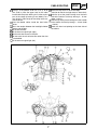
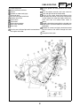
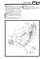
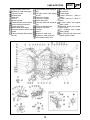
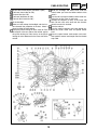
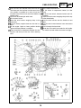
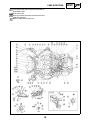
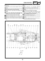
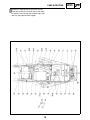
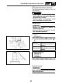
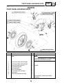
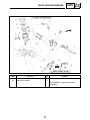
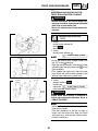
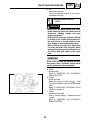
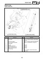
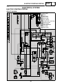
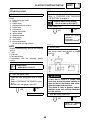
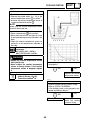
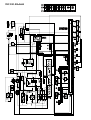
YZF-R6T
YZF-R6TC
SUPPLEMENTARY
SERVICE MANUAL
LIT-11616-18-45
5SL-28197-12
FOREWORD
This Supplementary Service Manual has been prepared to introduce new service and data for the
YZF-R6T / YZF-R6TC. For complete service information procedures it is necessary to use this Supplementary Service Manual together with the following manual.
YZF-R6R / YZF-R6SR / YZF-R6RC / YZF-R6SRC SERVICE MANUAL:
LIT-11616-16-45 (5SL-28197-10)
YZF-R6S / YZF-R6SC SUPPLEMENTARY SERVICE MANUAL: LIT-11616-17-46 (5SL-28197-11)
EAS00001
YZF-R6T / YZF-R6TC
SUPPLEMENTARY
SERVICE MANUAL
©2004 by Yamaha Motor
Corporation, U.S.A.
First edition, September 2004
All rights reserved. Any reproduction
or unauthorized use without the written
permission of Yamaha Motor Corporation,
U.S.A. is expressly prohibited.
Printed in U.S.A.
P / N LIT-11616-18-45
EAS00030
NOTICE
This manual was produced by the Yamaha Motor Company, Ltd. primarily for use by Yamaha dealers and their qualified mechanics. It is not possible to include all the knowledge of a mechanic in one
manual. Therefore, anyone who uses this book to perform maintenance and repairs on Yamaha
vehicles should have a basic understanding of mechanics and the techniques to repair these types
of vehicles. Repair and maintenance work attempted by anyone without this knowledge is likely to
render the vehicle unsafe and unfit for use.
This model has been designed and manufactured to perform within certain specifications in regard
to performance and emissions. Proper service with the correct tools is necessary to ensure that the
vehicle will operate as designed. If there is any question about a service procedure, it is imperative
that you contact a Yamaha dealer for any service information changes that apply to this model. This
policy is intended to provide the customer with the most satisfaction from his vehicle and to conform
to federal environmental quality objectives.
Yamaha Motor Company, Ltd. is continually striving to improve all of its models. Modifications and
significant changes in specifications or procedures will be forwarded to all authorized Yamaha dealers and will appear in future editions of this manual where applicable.
NOTE:
• This Service Manual contains information regarding periodic maintenance to the emission control
system. Please read this material carefully.
• Designs and specifications are subject to change without notice.
EAS00040
IMPORTANT MANUAL INFORMATION
Particularly important information is distinguished in this manual by the following.
The Safety Alert Symbol means ATTENTION! BECOME ALERT! YOUR
SAFETY IS INVOLVED!
WARNING
CAUTION:
NOTE:
Failure to follow WARNING instructions could result in severe injury or death
to the motorcycle operator, a bystander or a person checking or repairing the
motorcycle.
A CAUTION indicates special precautions that must be taken to avoid damage to the motorcycle.
A NOTE provides key information to make procedures easier or clearer.
EAS00007
HOW TO USE THIS MANUAL
This manual is intended as a handy, easy-to-read reference book for the mechanic. Comprehensive
explanations of all installation, removal, disassembly, assembly, repair and check procedures are
laid out with the individual steps in sequential order.
The manual is divided into chapters. An abbreviation and symbol in the upper right corner of
each page indicate the current chapter.
Refer to “SYMBOLS”.
Each chapter is divided into sections. The current section title is shown at the top of each page,
except in Chapter 3 (“PERIODIC CHECKS AND ADJUSTMENTS”), where the sub-section title(s)
appears.
Sub-section titles appear in smaller print than the section title.
To help identify parts and clarify procedure steps, there are exploded diagrams at the start of
each removal and disassembly section.
Numbers are given in the order of the jobs in the exploded diagram. A circled number indicates a
disassembly step.
Symbols indicate parts to be lubricated or replaced.
Refer to “SYMBOLS”.
A job instruction chart accompanies the exploded diagram, providing the order of jobs, names of
parts, notes in jobs, etc.
Jobs requiring more information (such as special tools and technical data) are described
sequentially.
EAS00008
SYMBOLS
The following symbols are not relevant to every
vehicle.
Symbols
to
indicate the subject of each
chapter.
General information
Specifications
Periodic checks and adjustments
Chassis
Engine
Cooling system
Fuel injection system
Electrical system
Troubleshooting
Symbols
to
indicate the following.
Serviceable with engine mounted
Filling fluid
Lubricant
Special tool
Tightening torque
Wear limit, clearance
Engine speed
Electrical data
Symbols
to
in the exploded diagrams
indicate the types of lubricants and lubrication
points.
Engine oil
Gear oil
Molybdenum-disulfide oil
Wheel-bearing grease
Lithium-soap-based grease
Molybdenum-disulfide grease
Symbols
to
in the exploded diagrams
indicate the following.
Apply locking agent (LOCTITE®)
Replace the part
CONTENTS
GENERAL INFORMATION
SPECIAL TOOLS. . . . . . . . . . . . . . . . . . . . . . . . . . . . . . . . . . . . . . . . .
1
SPECIFICATIONS
GENERAL SPECIFICATIONS . . . . . . . . . . . . . . . . . . . . . . . . . . . . . . .
ENGINE SPECIFICATIONS. . . . . . . . . . . . . . . . . . . . . . . . . . . . . . . . .
CHASSIS SPECIFICATIONS. . . . . . . . . . . . . . . . . . . . . . . . . . . . . . . .
ELECTRICAL SPECIFICATIONS . . . . . . . . . . . . . . . . . . . . . . . . . . . .
TIGHTENING TORQUES. . . . . . . . . . . . . . . . . . . . . . . . . . . . . . . . . . .
ENGINE TIGHTENING TORQUES . . . . . . . . . . . . . . . . . . . . . . . .
CHASSIS TIGHTENING TORQUES . . . . . . . . . . . . . . . . . . . . . . .
CABLE ROUTING . . . . . . . . . . . . . . . . . . . . . . . . . . . . . . . . . . . . . . . .
2
2
3
4
5
5
5
6
PERIODIC CHECKS AND ADJUSTMENTS
BLEEDING THE HYDRAULIC BRAKE SYSTEM . . . . . . . . . . . . . .
ADJUSTING THE FRONT FORK LEGS. . . . . . . . . . . . . . . . . . . . .
20
22
CHASSIS
FRONT WHEEL AND BRAKE DISCS. . . . . . . . . . . . . . . . . . . . . . . . .
FRONT AND REAR BRAKES . . . . . . . . . . . . . . . . . . . . . . . . . . . . . . .
FRONT BRAKE PADS . . . . . . . . . . . . . . . . . . . . . . . . . . . . . . . . . .
FRONT BRAKE MASTER CYLINDER . . . . . . . . . . . . . . . . . . . . . .
FRONT BRAKE CALIPERS . . . . . . . . . . . . . . . . . . . . . . . . . . . . . .
ASSEMBLING AND INSTALLING THE FRONT BRAKE MASTER
CYLINDER . . . . . . . . . . . . . . . . . . . . . . . . . . . . . . . . . . . . . . . . . . .
FRONT FORK . . . . . . . . . . . . . . . . . . . . . . . . . . . . . . . . . . . . . . . . . . .
FRONT FORK LEGS . . . . . . . . . . . . . . . . . . . . . . . . . . . . . . . . . . .
DISASSEMBLING THE FRONT FORK LEGS . . . . . . . . . . . . . . . .
CHECKING THE FRONT FORK LEGS . . . . . . . . . . . . . . . . . . . . .
ASSEMBLING THE FRONT FORK LEGS . . . . . . . . . . . . . . . . . . .
SWINGARM AND DRIVE CHAIN . . . . . . . . . . . . . . . . . . . . . . . . . . . .
CHECKING THE DRIVE CHAIN . . . . . . . . . . . . . . . . . . . . . . . . . . .
24
25
25
26
29
31
33
33
36
37
38
43
43
COOLING SYSTEM
RADIATOR. . . . . . . . . . . . . . . . . . . . . . . . . . . . . . . . . . . . . . . . . . . . . .
45
ELECTRICAL SYSTEM
ELECTRIC STARTING SYSTEM. . . . . . . . . . . . . . . . . . . . . . . . . . . . .
CIRCUIT DIAGRAM . . . . . . . . . . . . . . . . . . . . . . . . . . . . . . . . . . . .
TROUBLESHOOTING . . . . . . . . . . . . . . . . . . . . . . . . . . . . . . . . . .
COOLING SYSTEM . . . . . . . . . . . . . . . . . . . . . . . . . . . . . . . . . . . . . . .
CIRCUIT DIAGRAM . . . . . . . . . . . . . . . . . . . . . . . . . . . . . . . . . . . .
TROUBLESHOOTING . . . . . . . . . . . . . . . . . . . . . . . . . . . . . . . . . .
YZF-R6T / YZF-R6TC WIRING DIAGRAM
47
47
48
51
51
52
SPECIAL TOOLS
GEN
INFO
EAS00027
GENERAL INFORMATION
SPECIAL TOOLS
The following special tools are necessary for complete and accurate tune-up and assembly. Use
only the appropriate special tools as this will help prevent damage caused by the use of inappropriate tools or improvised techniques. Special tools, part numbers or both may differ depending on the
country. When placing an order, refer to the list provided below to avoid any mistakes.
NOTE:
• For U.S.A. and Canada, use part number starting with “YM-”, “YU-”, or “ACC-”.
• For others, use part number starting with “90890-”.
Tool No.
Tool name / Function
Damper rod holder
90890-01423
YM-01423
This tool is used to hold the damper rod
assembly when loosening or tightening the
damper rod assembly bolt.
Rod holder
90890-01434
YM-01434
This tool is used to support the damper
adjusting rod.
Fork spring compressor
90890-01441
YM-01441
This tool is used to disassemble or assemble
the front fork legs.
Fork seal driver
90890-01442
YM-01442
This tool is used to install the front fork’s oil
seal and dust seal.
1
Illustration
GENERAL SPECIFICATIONS / ENGINE SPECIFICATIONS
SPEC
SPECIFICATIONS
GENERAL SPECIFICATIONS
Item
Model code
Dimensions
Overall length
Overall width
Overall height
Seat height
Wheelbase
Minimum ground clearance
Minimum turning radius
Weight
Wet (with oil and a full fuel tank)
Maximum load (except motorcycle)
Standard
5SLR (USA except for CAL)
5SLS (CAL)
Limit
•••
2,045 mm (80.5 in)
690 mm (27.2 in)
1,105 mm (43.5 in)
830 mm (32.7 in)
1,385 mm (54.5 in)
145 mm (5.7 in)
3,800 mm (149.6 in)
•••
•••
•••
•••
•••
•••
•••
183 kg (404 lb) (USA except for CAL)
184 kg (406 lb) (CAL)
192 kg (423 lb) (USA except for CAL)
191 kg (421 lb) (CAL)
•••
•••
•••
•••
ENGINE SPECIFICATIONS
Item
Throttle bodies
Model (manufacturer) × quantity
ID mark
Standard
40EIS (MIKUNI) × 4
5SLM 30 (5SLR), 5SLS 40 (5SLS)
2
Limit
•••
•••
CHASSIS SPECIFICATIONS
SPEC
CHASSIS SPECIFICATIONS
Item
Frame
Caster angle
Trail
Front tire
Size
Model (manufacturer)
Rear tire
Model (manufacturer)
Tire pressure (cold)
0 ~ 90 kg (0 ~ 198 lb)
90 ~ 192 kg (198 ~ 426 lb)
(USA except for CAL)
90 ~ 191 kg (198 ~ 423 lb) (CAL)
High-speed riding
Front brakes
Brake lever free play
Brake discs
Diameter × thickness
Min. thickness
Master cylinder inside diameter
Rear brake
Brake pedal freeplay
Standard
Limit
24.5°
95 mm (3.74 in)
•••
•••
120 / 70 ZR17 M / C (55W)
Pilot POWER C (MICHELIN)
D218FM (DUNLOP)
•••
•••
Pilot POWER (MICHELIN)
D218M (DUNLOP)
•••
290 kPa (2.9 kgf / cm2, 2.9 bar, 41.3 psi)
290 kPa (2.9 kgf / cm2, 2.9 bar, 41.3 psi)
•••
•••
290 kPa (2.9 kgf / cm2, 2.9 bar, 41.3 psi)
290 kPa (2.9 kgf / cm2, 2.9 bar, 41.3 psi)
•••
•••
6.7 ~ 18.1 mm (0.26 ~ 0.71 in)
•••
310 × 4.5 mm (12.20 × 0.18 in)
•••
16 mm (0.63 in)
•••
4.0 mm
(0.16 in)
•••
4.3 ~ 9.0 mm (0.17 ~ 0.35 in)
•••
3
CHASSIS SPECIFICATIONS /
ELECTRICAL SPECIFICATIONS
Item
Front suspension
Spring
Free length
Installed length
Spring rate (K1)
Spring stroke (K1)
Inner tube outer diameter
Fork oil
Quantity (each front fork leg)
Level (from the top of the outer tube,
with the outer tube fully compressed,
and without the fork spring)
Spring preload adjusting positions
Minimum
Standard
Maximum
Rebound damping adjusting positions
Minimum*
Standard*
Maximum*
Compression damping adjusting
positions
Minimum*
Standard*
Maximum*
*from the fully turned-in position
Rear suspension
Spring
Free length
Installed length
Spring rate (K1)
Drive chain
Maximum 15-link section
SPEC
Standard
248.8 mm (9.80 in)
Limit
244.3 mm (9.62 in)
8.8 N / mm (0.90 kg / mm, 50.22 lb / in)
0 ~ 120 mm (0 ~ 4.7244 in)
41 mm (1.61 in)
243.8 mm
(9.60 in)
•••
•••
•••
•••
0.475 L (0.418 lmp qt, 0.502 US qt)
92 mm (3.62 in)
•••
•••
8
7
0
•••
•••
•••
10
6
1
•••
•••
•••
13
6
1
•••
•••
•••
167.5 mm (6.59 in)
157.5 mm (6.2 in)
103 N / mm (10.5 kg / mm, 587.83 lb / in)
•••
•••
•••
•••
239.3 mm
(9.42 in)
ELECTRICAL SPECIFICATIONS
Item
Ignition system
CDI unit model (manufacturer)
Fuses (amperage × quantity)
Radiator fan motor fuse
Standard
Limit
F8T828 (MITSUBISHI)
•••
15 A × 2
•••
4
SPEC
TIGHTENING TORQUES
TIGHTENING TORQUES
ENGINE TIGHTENING TORQUES
Fastener
Thread
size
Q’ty
Clutch boss
Nut
M20
Cylinder identification sensor
Bolt
M6
Item
Tightening torque
1
Nm
90
m•kg
9.0
1
7.5
0.75
Remarks
ft•lb
65 Use a lock
washer
5.4 Yamaha bond No.1215
CHASSIS TIGHTENING TORQUES
Thread
size
Item
Handlebar and front fork
Front fender and front fork
Rear brake master cylinder and footrest bracket
Front brake caliper and front fork
Front master cylinder bleed screw
Brake caliper bleed screw
Front wheel axle pinch bolt
M8
M6
M8
M10
M8
M8
M8
Tightening torque
Nm
32
6
13
35
6
5
21
m•kg
3.2
0.6
1.3
3.5
0.6
0.5
2.1
Remarks
ft•lb
2.3
4.3
9.4
25
4.3
3.6
15 See NOTE
NOTE:
1. Insert the front wheel axle from the right
side and tighten it with the flange bolt from
the left side to 91 Nm (9.1 m•kg, 66 ft•lb).
2. In the order from the pinch bolt
→ pinch
bolt
→ pinch bolt , tighten each bolt to
21 Nm (2.1 m•kg, 15 ft•lb) without performing temporary tightening.
3. Check that the end face of the axle head
and the end face of the fork side are flushmounted. If they are out of alignment, make
sure to fit them by adding the external force
by hand or with a plastic hammer, etc.
If the end face of the axle is not parallel to
the end face of the fork, align them so that
one point of the axle circumference is positioned on the end face of the fork.
At this stage, it can be accepted if the end
face of the axle becomes partially concave
to the end face of the fork.
4. In the order from the pinch bolt
→ pinch
bolt
→ pinch bolt , tighten each bolt to
21 Nm (2.1 m•kg, 15 ft•lb) without performing temporary tightening.
5
CABLE ROUTING
SPEC
CABLE ROUTING
Pass the right handlebar switch lead inside the
front brake hoses and over the throttle cables.
Install the throttle cables to the hook so that the
pulling side of the throttle cables is routed downward.
Pass the clutch cable through the guide.
Plastic locking tie shall be positioned at 15 mm
(0.59 in) below from the upper bracket.
Clamp the left handlebar switch lead to the front fork
with the plastic locking tie and cut the tip of the tie.
Clamp it to the protector section.
Clamping position should be 10 mm (0.39 in) or
lower from the top end of the under bracket.
Attach the horn lead to the hook on the steering
cover.
Right handlebar switch lead
Clutch cable
Main switch lead
Left handlebar switch lead
Throttle cable (return side)
Throttle cable (pull side)
Horn lead
Steering cover
Front brake hose
Throttle cables
Joint
6
CABLE ROUTING
Clamp it at the position of 50 mm (1.97 in) to 65
mm (2.56 in) from the upper face of the under
bracket with the plastic locking tie. Cut the surplus
part of the clamp tip leaving 2 mm (0.08 in) to 4
mm (0.16 in). Point the tip of the clamp to the outside of vehicle.
Pass the throttle cables inside the front brake
hoses.
Set in the coupler between the headlight’s hollow
section and the duct.
To the wire harness
To the front turn signal light (right)
Set the sub wire harness in the joint.
Do not catch the sub wire harness when the duct
is assembled.
To the front turn signal light (left)
7
SPEC
Install the relay to the rib of the headlight.
(Location for the left and right relays is alternative.)
Point the tip of the plastic locking tie to the front
side of the vehicle. Cut the tip leaving 2 ~ 10 mm
(0.08 ~ 0.39 in).
Point the tip of the plastic locking tie to the outside
of the vehicle. Cut the tip leaving 2 ~ 10 mm (0.08
~ 0.39 in).
Attach the horn lead pointing to the front side of
the vehicle.
CABLE ROUTING
Throttle stop screw
Coolant reservoir tank hose
Cover 8
Radiator fan motor lead (right)
Pickup coil lead
Rear tail / brake light switch lead
Radiator return hose
Coolant hose
Clutch cable
Coolant hose protector
Hose clamp assembly
Hose clamp
Pass the rear tail / brake light switch lead outside of
rear engine mount bolt.
8
SPEC
Pass the ignition coil lead outside of the radiator
hose.
Pass the coolant reservoir tank hose under the
frame and right side of the throttle body.
The tip of the clamp should be pointed to the
inside above the vehicle. Items to be clamped here
are the radiator fan motor lead (right), coolant reservoir tank hose and radiator return hoses (2
hoses).
Coupler should be placed within the shaded area
of the cover 8. (Extrusion below the shaded area is
prohibited.)
Radiator fan motor lead (right) should be entered
into the inside of the vehicle through the frame
hole.
Clamp the clutch cable.
CABLE ROUTING
Route the radiator fan motor lead (right) by the outside of the clutch cable.
Route the radiator fan motor lead (right) and clutch
cable by the inner side of the coolant reservoir
tank hose and radiator return hoses (2 hoses).
The punch mark starting point should be lower
than the clamp’s top end.
However, the aiming position of the punch mark
starting point should be 5 mm (0.20 in) below the
clamp’s bottom end.
Pass the clutch cable inside of the radiator hose.
Assemble as “ ” shown below when clamping.
Pass the pickup coil lead over the throttle stop
cable.
Tip of the plastic locking tie shall be pointed to the
inner side at the rear part of the vehicle.
9
SPEC
Clamp the clutch cable so that it is positioned in
this range.
Put and apply the hose clamp to it.
Clamp the clutch cable by routing the upper end of
the clamp along with the bottom end of the hose
clamp assembly.
CABLE ROUTING
SPEC
Pass the main switch lead under the left handlebar
switch lead and then to the right side of the vehicle.
Pass the throttle stop cable by the left side of the
side stand switch lead, oil level switch lead, A.C.
magneto lead and then to the right side of the vehicle.
Route the A.C. magneto lead, sidestand switch
lead and oil level switch lead so that they pass the
inner side of the barance pipe 3. (for CAL)
Pass the fuel tank drain hose and fuel tank
breather hose inside of the coolant reservoir tank
breather hose, coolant reservoir tank hose and
wire harness and then route it by the out side of
the starter motor lead.
Pass the coolant reservoir tank hose outside of the
fuel tank drain hose and fuel tank breather hose.
Throttle cable (return side)
Throttle cable (pull side)
Starter motor lead
Canister hose (for CAL)
Canister (for CAL)
Balance hose (for CAL)
Coolant reservoir tank breather hose
Bracket 2
Sidestand switch lead
Oil level switch lead
A.C. magneto lead
Radiator fan motor lead (left)
Fuel tank breather hose
Fuel tank drain hose
Coolant reservoir tank cover
Drive sprocket cover
Coolant reservoir tank
10
CABLE ROUTING
Pass the fuel tank drain hose, fuel tank breather
hose through the clamp of the coolant reservoir
tank.
Pass the coolant reservoir tank breather hose
through the clamp of under the coolant reservoir
tank.
Projection allowance from the coolant reservoir
tank cover shall be 30 to 50 mm (1.18 ~ 1.97 in).
Pass the oil level switch lead and sidestand switch
lead over the bracket 2.
Pass the oil level switch lead, and sidestand switch
lead through the clamp.
5 ~ 45 mm (0.20 ~ 1.77 in).
Clamp the A.C. magneto lead, oil level switch lead
and sidestand switch lead.
11
SPEC
Pass the sidestand switch lead, oil level switch
lead and A.C. magneto lead between the engine
stay and the engine.
To the throttle body
To the radiator fan motor relay and fuse box
Route the radiator fan motor lead (left) by the outside of the radiator inlet hose.
Pass the throttle cable between the guide of the
cover 2 and the frame.
Pass the radiator fan motor lead (left) through the
hole of the frame to the inner side of the vehicle.
To the horn
Pass the coolant reservoir tank breather hose
through the hole of the coolant reservoir tank
cover.
Order of ups and downs means no object.
Route it below the coolant reservoir tank.
CABLE ROUTING
Right handlebar switch lead
Radiator fan motor lead (right)
Sub wire harness
Headlight lead
Meter lead
Cover 8
Ignition coil lead
Throttle position sensor coupler
Coolant reservoir tank hose
Throttle stop cable
Speed sensor lead coupler
Crankshaft position sensor lead
coupler
Fuel tank breather hose (except
for CAL)
Fuel tank drain hose (except for
CAL)
Fuel hose (return side, except
for CAL)
Fuel pump 2 coupler
Fuel pump 1 coupler
Starter motor lead
Fuel hose (feed side, except for
CAL)
Crankcase breather hose
Throttle air vent hose
Fuse box
Cover 7
Radiator fan motor relay
Radiator fan motor lead (left)
Left handlebar switch lead
12
SPEC
Main switch lead
Wire harness
Throttle cables
Throttle sub-lead 1 (white 6
poles)
Throttle sub-lead 2 (black 6
poles)
Oil level switch lead coupler
(white 1 pole)
Sidestand switch lead coupler
(blue 2 poles)
A.C. magneto lead coupler
(white 3 poles)
Rear tail / brake light switch lead
coupler (brown 2 poles)
CABLE ROUTING
Neutral switch lead coupler (connector 1 pole)
Fuel hose (return side, for CAL)
Canister hose (for CAL)
Fuel hose (feed side, for CAL)
Fuel tank drain hose (for CAL)
To the headlight
Make sure not to drop the headlight sub wire harness beneath the projection of the duct. Check it
when installing the side cowling.
Clamp the plastic locking tie to the cover 8. Place
the coupler at the rear side of the vehicle against
the plastic locking tie. Point the tip of the plastic
locking tie to the downward in the inner side of the
vehicle.
13
SPEC
Route the headlight and meter leads under the
frame’s lower part from the hollow section of the
cover 2.
Pass the left and right handlebar switch leads outside of the air filter case air vent hose.
Connect the couplers (4 units) at the frame side
hole. Do not catch each lead and wire harness
when the cover 8 is attached.
From the radiator
Pass the coolant reservoir tank hose through forward the starter motor lead and speed sensor
lead.
Pass the speed sensor lead coupler and crankshaft position sensor lead coupler over the throttle
stop cable.
CABLE ROUTING
Pass the fuel tank breather hose and fuel tank
drain hose over the fuel hose and fuel return hose.
One rotation is possible for a twist of fuel tank
breather hose and fuel tank drain hose before an
engine clamp.
To the rear tail / brake light switch lead.
To the neutral switch
Insert the wire harness wrapping clamp to the
frame hole.
Pass the battery negative lead over the wire harness.
To the engine. Upper or lower position relation
against the heat protector is no object.
There should be no interference between the wire
harness and the tip of the rear frame attaching
bolts.
14
SPEC
To the coolant reservoir tank
To the intake air temperature sensor (air filter
case)
To the oil level switch, sidestand switch and A.C.
magneto
Install the wire harness wrapping clamp to the stay
of the throttle body.
Pass the wire harness over the throttle air vent
hose.
Pass the wire harness between frame and coolant
hose.
Pass it through the frame hole.
Route the main switch lead under the left handlebar switch lead and radiator fan motor lead (right).
CABLE ROUTING
Upper or lower position relation between the left
handlebar switch lead, right handlebar switch lead
and radiator fan motor lead (right) is no object.
Do not catch the coupler when the air filter case is
assembled.
Clamp the wire harness, left handlebar switch
lead, right handlebar switch lead, main switch
lead and radiator fan motor lead (right). Match
the taping positions of three leads except the
wire harness. Point the tip of the clamp to the
front side of the vehicle.
Sealing set of the cover can be either upper or
lower against the frame lower end. However, it
should not be caught.
To the main switch lead coupler
15
SPEC
Point the tip of the plastic locking tie to the rear
side of the vehicle.
To the fuse box and fan motor relay
Pass the throttle cables over the cover 2.
Branching leads to the fuse box and radiator fan
motor relay shall pass through the guide section
of the cover 2 under the wire harness and then
to the outside of the frame.
Clamp the wire harness, main switch lead
branch line, radiator fan motor lead (left), radiator fan motor lead (right).
Tip of the plastic locking tie should point to the
downward outside of the vehicle.
Branching harness from the wire harness.
Use the plastic locking tie to clamp the starter
motor lead at the protector section.
CABLE ROUTING
The clamp by the side of a hose comes below an
attachment clamp.
Insert until it sets.
Poss the canister hose over fuel return hose and
under the fuel hose.
Route it above the canister hose.
16
SPEC
CABLE ROUTING
SPEC
Push the starter motor lead in the clamping sections (two points) or the battery box assembly and
secure it.
Install to the deepest position of the rib of the battery box assembly.
Fit in the plastic cover of rivet to the main unit after
assembly.
Make sure to clamp the wire harness. (Tighten it
until the clamp latchet stops.)
Insert the turn signal light relay to the back end of
the rib in the battery box assembly.
Hook of the battery box assembly shall hook on
the upper face of the fuse box. (It should not be put
on the side face.)
Set the immobilizer unit couplers (two units) in the
right side space of the tool kit.
Starter motor lead
Battery
Battery positive lead
Starter relay
Bolt
Turn signal relay
Fuse box
Pressure sensor
Tail / brake light
Tool kit
ECU
Wire harness
Battery negative lead
Battery band
Battery box
Starting circuit cut-off relay
17
CABLE ROUTING
Insert it to the back end of the rib in the battery box
assembly.
The 20 mm (0.79 in) knob should be within this
range.
Pass the turn signal lead by the outside of the right
side attaching boss of the tail / brake light.
Connect the turn signal light lead couplers (two
leads).
Pass the turn signal light and license light leads
between the rear side ribs of the battery box
assembly and to the rear part of the vehicle.
Connect the license light leads (two leads).
Route the branching lead to the license light
behind the tail / brake light left side attaching boss.
Route the tail / brake light lead under the projection
part.
18
SPEC
Route the tail / brake light lead above the projection
part.
There should be no remarkable difference
between the tension on right and left bands.
Point the tool kit opening to the rear side of the
vehicle.
Connect the tail / brake light lead coupler.
Make sure that the hooks (four positions) of the
battery box assembly catch the upper surface.
(They should not run on the side face.)
When assembling ECU, make sure that the pawls
of the battery box assembly catch.
Route the fuse box lead under the ECU connection
coupler.
Install the wrapping clamp of the wire harness to
the hole of the battery box assembly.
CABLE ROUTING
Connect the negative lead and the wire harness.
Install the starting circuit cut-off relay to the deepest position after placing the tail / brake light lead
and turn signal light lead in the guide.
19
SPEC
BLEEDING THE HYDRAULIC BRAKE SYSTEM
CHK
ADJ
EAS00135
PERIODIC CHECKS AND
ADJUSTMENTS
BLEEDING THE HYDRAULIC BRAKE
SYSTEM
WARNING
Bleed the hydraulic brake system whenever:
• the system is disassembled.
• a brake hose is loosened, disconnected or
replaced.
• the brake fluid level is very low.
• brake operation is faulty.
NOTE:
• Be careful not to spill any brake fluid or allow
the brake fluid reservoir to overflow.
• When bleeding the hydraulic brake system,
make sure there is always enough brake fluid
before applying the brake. Ignoring this precaution could allow air to enter the hydraulic
brake system, considerably lengthening the
bleeding procedure.
• If bleeding is difficult, it may be necessary to
let the brake fluid settle for a few hours.
Repeat the bleeding procedure when the tiny
bubbles in the hose have disappeared.
1. Bleed:
• hydraulic brake system
a. Fill the brake fluid reservoir to the proper
level with the recommended brake fluid.
b. Install the brake fluid reservoir diaphragm.
c. Connect a clear plastic hose
tightly to
the bleed screw .
Front brake master cylinder
Front brake caliper
Rear brake caliper
NOTE:
Bleeding order of the front hydraulic brake system is the following order:
1. front brake master cylinder.
2. front brake calipers.
3. front brake master cylinder.
d. Place the other end of the hose into a container.
e. Slowly apply the brake several times.
20
BLEEDING THE HYDRAULIC BRAKE SYSTEM
CHK
ADJ
f.
Fully pull the brake lever or fully press
down the brake pedal and hold it in position.
g. Loosen the bleed screw.
NOTE:
Loosening the bleed screw will release the
pressure and cause the brake lever to contact
the throttle grip or the brake pedal to fully
extend.
h. Tighten the bleed screw and then release
the brake lever or brake pedal.
i. Repeat steps (e) to (h) until all of the air
bubbles have disappeared from the brake
fluid in the plastic hose.
j. Tighten the bleed screw to specification.
Bleed screw
6 Nm (0.6 m•kg, 4.3 ft•lb)
k. Fill the brake fluid reservoir to the proper
level with the recommended brake fluid.
Refer to “CHECKING THE BRAKE FLUID
LEVEL”.
WARNING
After bleeding the hydraulic brake system,
check the brake operation.
NOTE:
After bleeding air, the brake fluid may ooze
around the thread section of each bleed screw.
This phenomenon does not show the leakage
but the brake fluid that has been accumulated
in the thread of screw while bleeding air.
Please wipe off to make the parts clean.
21
ADJUSTING THE FRONT FORK LEGS
CHK
ADJ
EAS00155
ADJUSTING THE FRONT FORK LEGS
The following procedure applies to both of the
front fork legs.
WARNING
• Always adjust both front fork legs evenly.
Uneven adjustment can result in poor handling and loss of stability.
• Securely support the motorcycle so that
there is no danger of it falling over.
Spring preload
CAUTION:
• Grooves are provided to indicate the
adjustment position.
• Never go beyond the maximum or minimum adjustment positions.
1. Adjust:
• spring preload
a. Turn the adjusting bolt
.
Direction
Direction
in direction
or
Spring preload is
increased (suspension is
harder).
Spring preload is
decreased (suspension is
softer).
Adjusting positions
Minimum: 8
Standard: 7
Maximum: 0
Rebound damping
CAUTION:
Never go beyond the maximum or minimum
adjustment positions.
22
ADJUSTING THE FRONT FORK LEGS
CHK
ADJ
1. Adjust:
• rebound damping
a. Turn the adjusting screw
or .
Direction
Direction
in direction
Rebound damping is
increased (suspension is
harder).
Rebound damping is
decreased (suspension is
softer).
Adjusting positions
Minimum: 10 clicks in direction
*
Standard: 6 clicks in direction
*
Maximum: 1 clicks in direction
*
* with the adjusting screw fully turned-in
direction
Compression damping
CAUTION:
Never go beyond the maximum or minimum
adjustment positions.
1. Adjust:
• compression damping
a. Turn the adjusting screw
or .
Direction
Direction
in direction
Compression damping is
increased (suspension is
harder).
Compression damping is
decreased (suspension is
softer).
Adjusting positions
Minimum: 13 clicks in direction
*
Standard: 6 clicks in direction
*
Maximum: 1 clicks in direction
*
* with the adjusting screw fully turned-in
direction
23
FRONT WHEEL AND BRAKE DISCS
CHAS
EAS00514
CHASSIS
FRONT WHEEL AND BRAKE DISCS
6 Nm (0.6 m•kg, 4.3 ft•lb)
6 Nm (0.6 m•kg, 4.3 ft•lb)
35 Nm (3.5 m•kg, 25 ft•lb)
91 Nm (9.1 m•kg, 66 ft•lb)
21 Nm (2.1 m•kg, 15 ft•lb)
18 Nm (1.8 m•kg, 13 ft•lb)
Order
1
2
3
4
5
6
7
8
9
Job / Part
Removing the front wheel and brake
discs
Q’ty
Brake hose holder (left and right)
Front brake caliper (left and right)
Front wheel axle pinch bolt
Front wheel axle bolt
Front wheel axle
Collar (left and right)
Oil seal cover (left and right)
Front wheel
Front brake disc (left and right)
2
2
4
1
1
2
2
1
2
Remarks
Remove the parts in the order listed.
NOTE:
Place the motorcycle on a suitable stand
so that the front wheel is elevated.
Loosen.
For installation, reverse the removal
procedure.
24
FRONT AND REAR BRAKES
CHAS
EAS00577
FRONT AND REAR BRAKES
FRONT BRAKE PADS
5 Nm (0.5 m•kg, 3.6 ft•lb)
35 Nm (3.5 m•kg, 25 ft•lb)
6 Nm (0.6 m•kg, 4.3 ft•lb)
Order
1
2
3
4
5
6
7
Job / Part
Removing the front brake pads
Q’ty
Brake hose holder
Front brake caliper
Brake pad clip
Brake pad pin
Brake pad spring
Brake pad
Bleed screw
Remarks
Remove the parts in the order listed.
NOTE:
The following procedure applies to both of
the front brake calipers.
1
1
2
1
1
2
1
For installation, reverse the removal
procedure.
25
FRONT AND REAR BRAKES
CHAS
EAS00584
FRONT BRAKE MASTER CYLINDER
13 Nm (1.3 m•kg, 9.4 ft•lb)
30 Nm (3.0 m•kg, 22 ft•lb)
Order
1
2
3
4
5
6
7
8
9
10
11
12
Job / Part
Removing the front brake master
cylinder
Brake fluid
Q’ty
Stopper
Brake fluid reservoir cap
Brake fluid reservoir diaphragm holder
Brake fluid reservoir diaphragm
Brake fluid reservoir tank
Brake fluid reservoir hose
Brake lever
Front brake switch connector
Union bolt
Copper washer
Brake hose
Brake master cylinder bracket
1
1
1
1
1
1
1
2
1
2
1
1
26
Remarks
Remove the parts in the order listed.
Drain.
Refer to “CHANGING THE BRAKE
FLUID” in chapter 3.
Disconnect.
FRONT AND REAR BRAKES
CHAS
13 Nm (1.3 m•kg, 9.4 ft•lb)
30 Nm (3.0 m•kg, 22 ft•lb)
Order
13
14
Job / Part
Brake master cylinder
Front brake switch
Q’ty
1
1
Remarks
For installation, reverse the removal
procedure.
27
FRONT AND REAR BRAKES
CHAS
EAS00585
6 Nm (0.6 m•kg, 4.3 ft•lb)
Order
Job / Part
Disassembling the front brake
master cylinder
Brake master cylinder kit
Bleed screw
Brake master cylinder body
Q’ty
Remarks
Disassemble the parts in the order listed.
1
1
1
For assembly, reverse the disassembly
procedure.
28
FRONT AND REAR BRAKES
CHAS
EAS00613
FRONT BRAKE CALIPERS
6 Nm (0.6 m•kg, 4.3 ft•lb)
30 Nm (3.0 m•kg, 22 ft•lb)
35 Nm (3.5 m•kg, 25 ft•lb)
Order
Job / Part
Removing the front brake calipers
Q’ty
Brake fluid
1
2
3
4
Remarks
Remove the parts in the order listed.
NOTE:
The following procedure applies to both of
the front brake calipers.
Drain.
Refer to “BLEEDING THE HYDRAULIC
BRAKE SYSTEM”.
Union bolt
Copper washer
Brake hose
Brake caliper
1
2
1
1
For installation, reverse the removal
procedure.
29
FRONT AND REAR BRAKES
CHAS
EAS00615
5 Nm (0.5 m•kg, 3.6 ft•lb)
Order
Job / Part
Disassembling the front brake
calipers
Q’ty
Brake pad clip
Brake pad pin
Brake pad spring
Brake pad
Brake caliper piston
Brake caliper piston seal
Bleed screw
Remarks
Disassemble the parts in the order listed.
NOTE:
The following procedure applies to both of
the front brake calipers.
2
1
1
2
4
8
1
For assembly, reverse the disassembly
procedure.
30
FRONT AND REAR BRAKES
CHAS
EAS00607
ASSEMBLING AND INSTALLING THE
FRONT BRAKE MASTER CYLINDER
WARNING
• Before installation, all internal brake components should be cleaned and lubricated
with clean or new brake fluid.
• Never use solvents on internal brake components.
Recommended brake fluid
DOT 4
1. Install:
• brake master cylinder kit
• circlip
• dust boot
2. Install:
• brake master cylinder
13 Nm (1.3 m•kg, 9.4 ft•lb)
NOTE:
• Install the brake master cylinder holder with
the “UP” mark
facing up.
• Align the mating surfaces of the brake master
cylinder holder with the punch mark
on the
right handlebar.
• First, tighten the upper bolt, then the lower
bolt. Attach the brake master cylinder to the
vehicles inner side from a punch mark.
3. Install:
• copper washers
• brake hose
30 Nm (3.0 m•kg, 22 ft•lb)
• union bolt
• tail / brake light switch coupler
32° ~ 42°
37.6 mm
(1.48 in.)
65.1 mm
(2.56 in.)
WARNING
Proper brake hose routing is essential to
insure safe motorcycle operation. Refer to
“CABLE ROUTING”.
37.2 mm
(1.46 in.)
NOTE:
• While holding the brake hose, tighten the
union bolt as shown.
• Turn the handlebars to the left and right to
make sure the brake hose does not touch
other parts (e.g., wire harness, cables, leads).
Correct if necessary.
31
FRONT AND REAR BRAKES
CHAS
4. Fill:
• brake fluid reservoir
(with the specified amount of the recommended brake fluid)
Recommended brake fluid
DOT 4
WARNING
• Use only the designated brake fluid. Other
brake fluids may cause the rubber seals to
deteriorate, causing leakage and poor
brake performance.
• Refill with the same type of brake fluid that
is already in the system. Mixing brake fluids may result in a harmful chemical reaction, leading to poor brake performance.
• When refilling, be careful that water does
not enter the brake fluid reservoir. Water
will significantly lower the boiling point of
the brake fluid and could cause vapor
lock.
CAUTION:
Brake fluid may damage painted surfaces
and plastic parts. Therefore, always clean
up any spilt brake fluid immediately.
5. Bleed:
• brake system
Refer to “BLEEDING THE HYDRAULIC
BRAKE SYSTEM”.
6. Check:
• brake fluid level
Below the minimum level mark
→ Add
the recommended brake fluid to the proper
level.
Refer to “CHECKING THE BRAKE FLUID
LEVEL” in chapter 3.
7. Check:
• brake lever operation
Soft or spongy feeling → Bleed the brake
system.
Refer to “BLEEDING THE HYDRAULIC
BRAKE SYSTEM”.
32
FRONT FORK
CHAS
EAS00647
FRONT FORK
FRONT FORK LEGS
32 Nm (3.2 m•kg, 23 ft•lb)
26 Nm (2.6 m•kg, 19 ft•lb)
6 Nm (0.6 m•kg, 4.3 ft•lb)
Order
1
2
3
4
5
6
Job / Part
Removing the front fork legs
Front wheel
23 Nm (2.3 m•kg, 17 ft•lb)
Q’ty
Front brake calipers
Front cowling inner panels
Front fender
Cap bolt
Handlebar pinch bolt
Upper bracket pinch bolt
Under bracket pinch bolt
Front fork leg
1
1
1
1
2
1
Remarks
Remove the parts in the order listed.
Refer to “FRONT WHEEL AND BRAKE
DISCS”.
Refer to “FRONT AND REAR BRAKES”.
Refer to “COWLINGS” in chapter 3.
Loosen.
Loosen.
Loosen.
Loosen.
For installation, reverse the removal
procedure.
33
FRONT FORK
CHAS
EAS00648
15 Nm (1.5 m•kg, 11 ft•lb)
23 Nm (2.3 m•kg, 17 ft•lb)
23 Nm (2.3 m•kg, 17 ft•lb)
Order
Job / Part
Disassembling the front fork legs
Q’ty
Cap bolt
O-ring
Damper adjusting rod
Nut
Washer
Spacer
Fork spring
Dust seal
Oil seal clip
Oil seal
1
1
1
1
1
1
1
1
1
1
34
Remarks
Disassemble the parts in the order listed.
NOTE:
The following the procedure applies to
both of the front fork legs.
FRONT FORK
CHAS
15 Nm (1.5 m•kg, 11 ft•lb)
23 Nm (2.3 m•kg, 17 ft•lb)
23 Nm (2.3 m•kg, 17 ft•lb)
Order
Job / Part
Washer
Damper rod assembly bolt
Copper washer
Damper rod assembly
Inner tube
Outer tube
Q’ty
1
1
1
1
1
1
Remarks
For assembly, reverse the disassembly
procedure.
35
FRONT FORK
CHAS
EAS00652
DISASSEMBLING THE FRONT FORK LEGS
The following procedure applies to both of the
front fork legs.
1. Remove:
• cap bolt
(from the damper adjusting rod)
• spacer
• nut
a. Press down on the spacer with the fork
spring compressor .
b. Install the rod holder
between the nut
and the spacer .
Fork spring compressor
90890-01441, YM-01441
Rod holder
90890-01434, YM-01434
NOTE:
Use the side of the rod holder that is marked
“B”.
c. Loosen the nut.
d. Remove the cap bolt.
e. Remove the rod holder and fork spring
compressor.
WARNING
The fork spring is compressed.
f.
Remove the spacer and nut.
2. Drain:
• fork oil
NOTE:
Stroke the damper rod
draining the fork oil.
several times while
3. Remove:
• dust seal
• oil seal clip
• oil seal
• washer
(with a flat-head screwdriver)
CAUTION:
Do not scratch the inner tube.
36
FRONT FORK
CHAS
4. Remove:
• damper rod assembly bolt
• damper rod assembly
NOTE:
While holding the damper rod assembly with
the damper rod holder , loosen the damper
rod assembly bolt.
Damper rod holder
90890-01423, YM-01423
EAS00656
CHECKING THE FRONT FORK LEGS
The following procedure applies to both of the
front fork legs.
1. Check:
• inner tube
• outer tube
Bends / damage / scratches → Replace.
WARNING
Do not attempt to straighten a bent inner
tube as this may dangerously weaken it.
2. Measure:
• spring free length
Out of specification → Replace.
Spring free length
248.8 mm (9.80 in)
<Limit> : 243.8 mm (9.60 in)
3. Check:
• damper rod
Damage / wear → Replace.
Obstruction → Blow out all of the oil passages with compressed air.
• damper rod adjusting rod
Bends / damage → Replace.
37
FRONT FORK
CHAS
CAUTION:
• The front fork leg has a built-in damper
adjusting rod and a very sophisticated
internal construction, which are particularly sensitive to foreign material.
• When disassembling and assembling the
front fork leg, do not allow any foreign
material to enter the front fork.
4. Check:
• cap bolt O-ring
Damage / wear → Replace.
EAS00659
ASSEMBLING THE FRONT FORK LEGS
The following procedure applies to both of the
front fork legs.
WARNING
• Make sure the oil levels in both front fork
legs are equal.
• Uneven oil levels can result in poor handling and a loss of stability.
NOTE:
• When assembling the front fork leg, be sure
to replace the following parts:
– outer tube bushing
– oil seal
– dust seal
– Before assembling the front fork leg, make
sure all of the components are clean.
1. Install:
• inner tube
• damper rod assembly
• damper rod assembly bolt
• copper washer
38
FRONT FORK
CHAS
WARNING
Always use new copper washer.
CAUTION:
Allow the damper rod assembly to slide
slowly down the inner tube
until it protrudes from the bottom of the inner tube.
Be careful not to damage the inner tube.
2. Lubricate:
• inner tube’s outer surface
Recommended lubricant
Suspension oil “01” or
equivalent
3. Tighten:
• damper rod assembly bolt
23 Nm (2.3 m•kg, 17 ft•lb)
LOCTITE®
NOTE:
While holding the damper rod assembly with
the damper rod holder , tighten the damper
rod assembly bolt.
Damper rod holder
90890-01423, YM-01423
4. Install:
• dust seal
• oil seal clip
• oil seal
• washer
39
FRONT FORK
CHAS
CAUTION:
Make sure the numbered side of the oil seal
faces up.
NOTE:
• Before installing the oil seal, lubricate its lips
with lithium-soap-based grease.
• Lubricate the outer surface of the inner tube
with fork oil.
• Before installing the oil seal, cover the top of
the front fork leg with a plastic bag to protect
the oil seal during installation.
5. Install:
• oil seal
(with the fork seal driver
)
Fork seal driver
90890-01442, YM-01442
6. Install:
• oil seal clip
NOTE:
Adjust the oil seal clip so that it fits into the
outer tube’s groove.
7. Install:
• dust seal
(with the fork seal driver weight
Fork seal driver
90890-01442, YM-01442
40
)
FRONT FORK
8. Install:
• rod puller
• rod puller attachment
(onto the damper rod
CHAS
)
Rod puller
90890-01437, YM-01437
Rod puller attachment
90890-01436, YM-01436
9. Fill:
• front fork leg
(with the specified amount of the recommended fork oil)
Quantity (each front fork leg)
0.475 L (0.418 Imp qt,
0.502 US qt)
Recommended oil
Suspension oil “01” or
equivalent
Front fork leg oil level (from the
top of the outer tube, with the
outer tube fully compressed and
without the fork spring)
92 mm (3.62 in)
NOTE:
• While filling the front fork leg, keep it upright.
• After filling, slowly pump the front fork leg up
and down to distribute the fork oil.
10.Install:
• nut
• fork spring
• spacer
• damper adjusting rod
• cap bolt
a. Remove the rod puller and adapter.
b. Install the nut.
c. Install the fork spring, and spacer.
d. Install the rod puller and adapter.
NOTE:
Install the spring with the smaller pitch
ing up .
41
fac-
FRONT FORK
CHAS
e. Press down on the spacer with the fork
spring compressor .
f. Pull up the rod puller and install the rod
holder
between the nut
and the
spacer .
NOTE:
Use the side of the rod holder that is marked
“B”.
Fork spring compressor
90890-01441, YM-01441
Rod holder
90890-01434, YM-01434
g. Remove the rod puller and adapter.
h. Install the nut
and position it as specified .
Distance
11 mm (0.43 in)
i.
Set the cap bolt distance
tion.
to specifica-
Distance
13 mm (0.51 in)
j.
Install the damper adjusting rod and cap
bolt, and then finger tighten the cap bolt.
k. Hold the cap bolt and tighten the nut to
specification.
Nut
15 Nm (1.5 m•kg, 11 ft•lb)
l.
Remove the rod holder and fork spring
compressor.
WARNING
• The fork spring is compressed.
• Always use a new cap bolt O-ring.
42
SWINGARM AND DRIVE CHAIN
CHAS
EAS00709
SWINGARM AND DRIVE CHAIN
CHECKING THE DRIVE CHAIN
1. Measure:
• Measure the dimension between 15-links
on the inner side
and outer side
of the
roller and calculate the dimension between
pin centers.
• Dimension
between pin centers = (Inner
dimension
+ Outer dimension ) / 2
• 15-link section
of the drive chain
Out of specification → Replace the drive
chain, front drive sprocket and rear drive
sprocket as a set.
15-link drive chain section limit
(maximum)
239.3 mm (9.42 in)
NOTE:
• While measuring the 15-link section, push
down on the drive chain to increase its tension.
• Perform this measurement at two or three different places.
2. Check:
• drive chain
Stiffness → Clean and lubricate or replace.
3. Clean:
• drive chain
a. Wipe the drive chain with a clean cloth.
b. Put the drive chain in kerosene and remove
any remaining dirt.
c. Remove the drive chain from the kerosene
and completely dry it.
43
SWINGARM AND DRIVE CHAIN
CHAS
CAUTION:
This motorcycle has a drive chain with
small rubber O-rings
between the drive
chain side plates. Never use high-pressure
water or air, steam, gasoline, certain solvents (e.g., benzine), or a coarse brush to
clean the drive chain. High-pressure methods could force dirt or water into the drive
chain’s internals, and solvents will deteriorate the O-rings. A coarse brush can also
damage the O-rings. Therefore, use only
kerosine to clean the drive chain.
4. Check:
• O-rings
Damage → Replace the drive chain.
• drive chain rollers
Damage / wear → Replace the drive chain.
• drive chain side plates
Damage / wear → Replace the drive chain.
Cracks → Replace the drive chain and
make sure that the battery breather hose is
properly routed away from the drive chain
and below the swingarm.
5. Lubricate:
• drive chain
Recommended lubricant
Engine oil or chain lubricant
suitable for O-ring chains
6. Check:
• drive sprocket
• rear wheel sprocket
More than 1 / 4 tooth
wear → Replace the
drive chain sprockets as a set.
Bent teeth → Replace the drive chain
sprockets as a set.
Correct
Drive chain roller
Drive chain sprocket
44
RADIATOR
EAS00454
COOL
COOLING SYSTEM
RADIATOR
10 Nm (1.0 m•kg, 7.2 ft•lb)
Order
1
2
3
4
5
6
7
8
7 Nm (0.7 m•kg, 5.1 ft•lb)
Job / Part
Removing the radiator
Rider seat
Fuel tank
Air filter case
Side cowlings and bottom cowling
Coolant
Q’ty
Coolant reservoir hose
Throttle body hose
Radiator outlet hose
Coolant pipe
Radiator inlet hose
Oil cooler outlet hose
Radiator
Radiator fan
1
2
1
1
1
1
1
2
45
12 Nm (1.2 m•kg, 8.7 ft•lb)
Remarks
Remove the parts in the order listed.
Refer to “SEATS” in chapter 3.
Refer to “FUEL TANK” in chapter 3.
Refer to “AIR FILTER CASE” in chapter 3.
Refer to “COWLINGS” in chapter 3.
Drain
Refer to “CHANGING THE COOLANT” in
chapter 3.
RADIATOR
10 Nm (1.0 m•kg, 7.2 ft•lb)
Order
9
Job / Part
Radiator cap
7 Nm (0.7 m•kg, 5.1 ft•lb)
Q’ty
1
COOL
12 Nm (1.2 m•kg, 8.7 ft•lb)
Remarks
For installation, reverse the removal
procedure.
46
ELECTRIC STARTING SYSTEM
EAS00755
ELEC
ELECTRICAL SYSTEM
ELECTRIC STARTING SYSTEM
CIRCUIT DIAGRAM
Main switch
Battery
Fuse (main)
Starter relay
Starter motor
Fuse (ignition)
Starting circuit cut-off relay
Sidestand switch
Neutral switch
Engine stop switch
Start switch
Clutch switch
47
ELECTRIC STARTING SYSTEM
ELEC
EAS00739
EAS00757
TROUBLESHOOTING
2. Battery
• Check the condition of the battery.
Refer to “CHECKING AND CHARGING
THE BATTERY” in chapter 3.
The starter motor fails to turn.
Check:
1. main and ignition fuses
2. battery
3. starter motor
4. starting circuit cut-off relay
5. starter relay
6. main switch
7. engine stop switch
8. neutral switch
9. sidestand switch
10. clutch switch
11. start switch
12. wiring connections
(of the entire starting system)
NOTE:
• Before troubleshooting, remove the following
part(s):
1. seat
2. fuel tank
3. left side cowling
• Troubleshoot with the following special
tool(s).
Minimum open-circuit voltage
12.8 V or more at 20°C (68°F)
• Is the battery OK?
NO
YES
• Clean the battery
terminals.
• Recharge
or
replace the battery.
EAS00758
3. Starter motor
• Connect the positive battery terminal
and starter motor lead
with a jumper
lead .
.
Pocket tester
90890-03112, YU-3112
EAS00738
1. Main and ignition fuses
WARNING
• Check the main and ignition fuses for continuity.
Refer to “CHECKING THE FUSES” in chapter 3.
• Are the main and ignition fuses OK?
YES
• A wire that is used as a jumper lead
must have at least the same capacity or
more as that of the battery lead, otherwise the jumper lead may burn.
• This check is likely to produce sparks,
therefore make sure nothing flammable
is in the vicinity.
NO
Replace the fuse(s).
• Does the starter motor turn?
YES
NO
Repair or replace
the starter motor.
48
ELECTRIC STARTING SYSTEM
ELEC
EAS00759
4. Starting circuit cut-off relay
• Disconnect the starting circuit cut-off relay
coupler from the wire harness.
• Connect the pocket tester (Ω × 1) and battery (12 V) to the starting circuit cut-off relay
coupler as shown.
Positive battery terminal → red / black
Negative battery terminal →
black / yellow
• Does the starter relay have continuity
between red and black?
Positive tester probe → blue / white
Negative tester probe → blue / white
YES
NO
Replace the starter
relay.
EAS00749
6. Main switch
• Check the main switch for continuity.
Refer to “CHECKING THE SWITCHES”.
• Is the main switch OK?
• Does the starting circuit cut-off relay have
continuity between blue / white and blue/
white?
YES
NO
YES
NO
Replace the main
switch.
Replace the starting
circuit cut-off relay.
EAS00750
7. Engine stop switch
• Check the engine stop switch for continuity.
Refer to “CHECKING THE SWITCHES”
• Is the engine stop switch OK?.
EAS00761
5. Starter relay
• Disconnect the starter relay coupler from
the coupler.
• Connect the pocket tester (Ω × 1) and battery (12 V) to the starter relay coupler as
shown.
YES
NO
Replace the right
handlebar switch.
Positive battery terminal → red / white
Negative battery terminal →
blue / white
EAS00751
8. Neutral switch
Positive tester probe → red
Negative tester probe → black
• Check the neutral switch for continuity.
Refer to “CHECKING THE SWITCHES”.
• Is the neutral switch OK?
YES
NO
Replace the neutral
switch.
49
ELECTRIC STARTING SYSTEM
ELEC
EAS00766
EAS00752
9. Sidestand switch
12. Wiring
• Check the sidestand switch for continuity.
Refer to “CHECKING THE SWITCHES”.
• Is the sidestand switch OK?
• Check the entire starting system’s wiring.
Refer to “CIRCUIT DIAGRAM”.
• Is the starting system’s wiring properly connected and without defects?
YES
NO
YES
Replace the sidestand switch.
The starting system
circuit is OK.
EAS00763
10. Clutch switch
• Check the clutch switch for continuity.
Refer to “CHECKING THE SWITCHES”.
• Is the clutch switch OK?
YES
NO
Replace the clutch
switch.
EAS00764
11. Start switch
• Check the start switch for continuity.
Refer to “CHECKING THE SWITCHES”.
• Is the start switch OK?
YES
NO
Replace the right
handlebar switch.
50
NO
Properly connect or
repair the starting
system’s wiring.
COOLING SYSTEM
EAS00807
COOLING SYSTEM
CIRCUIT DIAGRAM
Main switch
Battery
Fuse (main)
Fuse (ignition)
ECU
Coolant temperature sensor
Radiator fan motor relay
Fuse (radiator fan motor left)
Fuse (radiator fan motor right)
Radiator fan motor (left)
Radiator fan motor (right)
51
ELEC
COOLING SYSTEM
ELEC
EAS00739
EAS00808
TROUBLESHOOTING
2. Battery
• Check the condition of the battery.
Refer to “CHECKING AND CHARGING
THE BATTERY” in chapter 3.
• The radiator fan motor fails to turn.
• The coolant temperature indicator light
fails to light when the engine is warm.
Minimum open-circuit voltage
12.8 V or more at 20°C (68°F)
Check:
1. main, ignition, and radiator fan motor fuses
2. battery
3. main switch
4. radiator fan motor
5. radiator fan motor relay
6. coolant temperature sensor
7. wiring connections
(the entire cooling system)
NOTE:
• Before troubleshooting, remove the following
part(s):
1. seat
2. fuel tank
3. bottom cowling
4. side cowlings
• Troubleshoot with the following special
tool(s).
• Is the battery OK?
YES
• Clean the battery
terminals.
• Recharge
or
replace the battery.
EAS00749
3. Main switch
• Check the main switch for continuity.
Refer to “CHECKING THE SWITCHES”.
• Is the main switch OK?
YES
NO
Replace the main
switch.
Pocket tester
90890-03112, YU-3112
EAS00738
1. Main, ignition and radiator fan motor
fuses
• Check the main, ignition and radiator fan
motor fuses for continuity.
Refer to “CHECKING THE FUSES” in chapter 3.
• Are the main, ignition and radiator fan motor
fuses OK?
YES
NO
NO
Replace the fuse(s).
52
COOLING SYSTEM
ELEC
EAS00809
4. Radiator fan motor (left and right)
5. Radiator fan motor relay
• Disconnect the radiator fan motor coupler
from the wire harness.
• Connect the battery (DC 12 V) as shown.
• Disconnect the radiator fan motor relay from
the wire harness.
• Connect the pocket tester (Ω × 1) and battery (12 V) to the radiator fan motor terminal
as shown.
• Check the radiator fan motor of continuity.
Battery positive terminal → red / white
Battery negative terminal →
green / yellow
Tester positive probe → black
Tester negative probe → black
Positive battery lead → blue
Negative battery lead → black
• Does the radiator fan motor turn?
YES
NO
The radiator fan
motor is faulty and
must be replaced.
• Does the radiator fan motor relay have continuity between black
and black ?
YES
NO
Replace the radiator
fan motor relay.
53
COOLING SYSTEM
ELEC
EAS00812
6. Coolant temperature sensor
• Remove the coolant temperature sensor.
• Connect the pocket tester (Ω × 1k) to the
coolant temperature sensor
as shown.
• Immerse the coolant temperature sensor in
a container filled with coolant .
NOTE:
Make sure the coolant temperature sensor
terminals do not get wet.
• Place a thermometer
in the coolant.
• Slowly heat the coolant, and then let it cool
to the specified temperature indicated in the
table.
• Check the coolant temperature sensor for
continuity at the temperatures indicated in
the table.
Coolant temperature sensor
resistance
0°C (32°F): 5.21 ~ 6.37 kΩ
80°C (176°F): 0.29 ~ 0.35 kΩ
WARNING
• Handle the coolant temperature sensor
with special care.
• Never subject the coolant temperature
sensor to strong shocks. If the coolant
temperature sensor is dropped, replace
it.
• Does the coolant temperature sensor operate properly?
YES
NO
Replace the coolant
temperature sensor.
Coolant temperature sensor
20 Nm (2.0 m•kg, 14 ft•lb)
Three bond sealock® 10
EAS00813
7. Wiring
• Check the entire cooling system’s wiring.
Refer to “CIRCUIT DIAGRAM”.
• Is the cooling system’s wiring properly connected and without defects?
YES
This circuit is OK.
54
NO
Properly connect or
repair the cooling
system’s wiring.
YZF-R6T/YZF-R6TC WIRING DIAGRAM
YZF-R6T / YZF-R6TC WIRING DIAGRAM
Main switch
A.C. magneto
Rectifier / regulator
Fuse (backup)
Battery
Fuse (main)
Starter relay
Starter motor
Fuse (fuel injection)
Fuse (ignition)
Starting circuit cut-off relay
Sidestand switch
Fuel pump
ECU
Ignition coil
Spark plug
Fuel injector
Air induction system solenoid
Neutral switch
Crankshaft position sensor
Intake air temperature sensor
Coolant temperature sensor
Throttle position sensor
Intake air pressure sensor
Atmospheric pressure sensor
Cylinder identification sensor
Speed sensor
Lean angle cut-off switch
Meter assembly
Fuel level warning light
Oil level warning light
Neutral indicator light
Tachometer
Shift timing indicator light
Multi-function meter
Engine trouble warning light
Coolant temperature indicator light
High beam indicator light
Turn signal indicator light
Meter light
Oil level switch
Right handlebar switch
Front brake light switch
Engine stop switch
Start switch
Fuse (signal)
Fuse (headlight)
Radiator fan motor relay
Fuse (radiator fan motor left)
Fuse (radiator fan motor right)
Radiator fan motor (left)
Radiator fan motor (right)
Headlight relay (on / off)
Headlight relay (dimmer)
Rear brake light switch
Left handlebar switch
Clutch switch
Dimmer switch
Horn switch
Turn signal switch
Horn
Turn signal relay
Rear turn signal light (right)
Rear turn signal light (left)
Front turn signal / position light (right)
Front turn signal / position light (left)
Headlight
License light
Tail / brake light
COLOR CODE
B. . . . . . .
Br . . . . . .
Ch. . . . . .
Dg. . . . . .
Gy. . . . . .
L. . . . . . .
Lg . . . . . .
O ......
P. . . . . . .
R. . . . . . .
Sb. . . . . .
W ......
Y. . . . . . .
B/L . . . . .
B / R. . . . .
B/W . . . .
B / Y. . . . .
Br / L . . . .
Br / R . . . .
Br / W. . . .
Br / Y . . . .
G/B . . . .
G/W . . . .
G/Y . . . .
Gy / G . . .
Gy / R . . .
L/B . . . . .
L/R . . . . .
L/W . . . .
L/Y . . . . .
O/B . . . .
O/G . . . .
P/W . . . .
R / B. . . . .
R/G . . . .
R/L . . . . .
R/W . . . .
R / Y. . . . .
Sb / W . . .
W/B . . . .
W/Y . . . .
Y / B. . . . .
Y/G . . . .
Y/L . . . . .
Y / R. . . . .
Y/W . . . .
Black
Brown
Chocolate
Dark green
Gray
Blue
Light green
Orange
Pink
Red
Sky blue
White
Yellow
Black / Blue
Black / Red
Black / White
Black / Yellow
Brown / Blue
Brown / Red
Brown / White
Brown / Yellow
Green / Black
Green / White
Green / Yellow
Gray / Green
Gray / Red
Blue / Black
Blue / Red
Blue / White
Blue / Yellow
Orange / Black
Orange / Green
Pink / White
Red / Black
Red / Green
Red / Blue
Red White
Red / Yellow
Sky blue/White
White / Black
White / Yellow
Yellow / Black
Yellow / Green
Yellow / Blue
Yellow / Red
Yellow / White
YAMAHA MOTOR CO., LTD.
2500 SHINGAI IWATA SHIZUOKA JAPAN


![Manuale Officina [ ITA ] Yamaha R1 2002-2003](http://vs1.manualzilla.com/store/data/006110674_1-52d32bbc9127defc0419b49b1226ec2b-150x150.png)