1
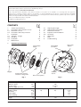
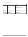
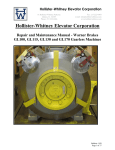
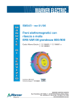
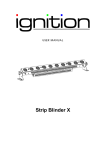
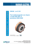
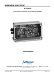
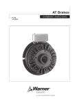
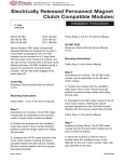
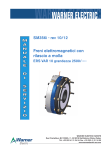
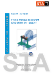
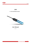
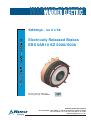
SM366gb - rev 01/06
S
E
R
V
I
C
E
Electrically Released Brakes
ERS VAR10 SZ 5000/5000
M
A
N
U
A
L
EC type certificate ABV 604/1
according drawing 1 12 106602
WARNER ELECTRIC EUROPE
Rue Champfleur, B.P. 20095, F- 49182 St Barthélemy d’Anjou Cedex
Tél. +33 (0)2 41 21 24 24, Fax + 33 (0)2 41 21 24 00
www.warnerelectric-eu.com
We: WARNER ELECTRIC EUROPE, 7, rue Champfleur, B.P. 11095, F-49182 St Barthélemy d’Anjou Cedex
declare that the brakes made in our factories from St Barthélemy d’Anjou,
and hereafter designated: ERS VAR10 SZ 5000/5000
Fully comply with directive 95/16/EC on Lifts and are intended for incorporation into an installation or for assembly with other equipment,
with the aim of constituting a machine subject to the application of directive 98/37/EC and the directive on Electromagnetic Compatibility
89/336 (modified). Compliance with the basic requirements of the Low Voltage Directive 73/23 (modified) is guaranteed by our full compliance
with the following standards: NFC 79300 and VDE 0580/8.65.
Drawn up in St Barthélemy d’Anjou, July 2002
E. PRAT, General Managing Director
CONTENTS
1
2
2.1
2.2
3
3.1
3.2
3.3
4
Technical specifications
Precautions and restrictions on use
Restrictions on use
Precautions and safety measures
Installation
Transport - storage
Handling
Installation
Maintenance
1
Technical specifications
2
3
3
3
3
3
3
3-4
4
4.1
4.2
5
5.1
5.2
6
7
8
Intermediate
flange
Adjusting the airgap
Adjusting the microswitch
Electrical connection
Important recommendations
Connector
Spare parts
Tools
Troubleshooting
4
4
4
4
5
5
5
6
Dust cover
(option)
Thread M16
(2 x 180°)
O-rings
Hub
Magnet
Friction discs heel on
customer’s flange side
Transport
screws
Dust cover (option)
Fig. 1
Table 1
Nominal holding torque
Maximum speed
Nominal airgap
Maximum airgap after wear
OEX voltage
Holding voltage
Resistance
Power (OEX)
Power (holding)
Cyclic duration factor
Weight
Thread M10
Fig. 2
Nm
min-1
mm
mm
VDC
VDC
Ω
Watt
Watt
ED
kg
48
24
-
ERS VAR10 SZ 5000/5000
5200
120
0,5 ±0,1
0,8
103,5
52
50 %
124
WARNER ELECTRIC EUROPE - Rue Champfleur, B.P. 20095, F - 49182 St Barthélemy d’Anjou Cedex
207
103,5
101
428
107
SM366gb - rev 01/06
2/6
Symbol designating
an action that might
damage the brake
Symbol designating an
action that might be dangerous to human safety
Symbol designating an electrical action that might be
dangerous to human safety
2
Precautions and restrictions on use
3
Installation
2.1
Restrictions on use
3.1
Transport / storage
For the brake to comply with directive 95 / 16 / EC,
the integrator must observe the general conditions
for installations and use as defi ned in the EC type certificate ref. ABV 604/1 of 12th Feb. 2003 drawn up by the
TUV Munich, including the mandatory use of a speed
limiting device, in compliance with EN 81-1 paragraph 9.9
subpoint 9.10.10.
This brake is delivered in standard packaging that will
keep it intact for a period of 6 months during ground,
air or sea transport towards neighbouring continents
(without crossing the tropics).
3.2
Avoid any impact to the brake so that its performance is not impaired.
This brake is designed to work in dry conditions.
Friction faces must be kept completely clean of
any oil, grease or abrasive dust.
When handling, use the handling holes (M16 and
M12) intended for this purpose (See Fig. 2).
If maximum rotation speeds are exceeded, the
guarantee is no longer valid.
This brake may only be used in a “horizontal
axis”. The customer must be careful not to alter
the factory-set airgap, this is in order to ensure the brakes
may be properly released.
This brake is designed for a maximum ambient
temperature of 40°C (coating class 155°C). The
maximum temperature in continual use is 100°C.
This brake is designed for static applications.
Any dynamic braking is restricted to emergency
braking and test braking. This brake can in no way replace
the safety braking system used during lift descent.
2.2
Handling
Never lift the brake by its cables.
3.3
Installation
The brake is delivered pre-assembled with pre-set
microswitches and airgaps. Fixing screws, the hub and
the O-rings are supplied separately.
Specifications for the customer‘s friction face :
Material: Steel (150 to 250 HV) or cast iron
Roughness ≤ Ra 3,2
Protection : Phosphatizing (dry) or nitriding
Geometric tolerances :
0,1
0,1
Precautions and safety measures
During maintenance, make sure that the mechanism to be braked by the brake, is stopped and
that there is no risk of it accidentally starting up. All intervention have to be made by qualified personnel, owning
this manual.
Customer's shaft axis
• Tighten the 3 transport screws CHc M10
• Put the hub into position on the customer’s shaft
• Put the shock absorbing O-rings onto the hub (see
Fig.1)
Any modification made to the brake without the
express authorisation of a representative of Warner
Electric, in the same way than any use out of the contractual specifications accepted by "Warner Electric", will result
in the warranty being invalidated and Warner Electric will
no longer be liable in any way with regard to conformity.
When switching on DC-side the coil must be
protected against voltage peaks.
• Engage the front disc on the hub, heel on the flange side
(see Fig.1)
Caution: When installing and should the brake ever be
taken apart, make sure that the friction disc heel is the
right way round when the brake is put back together
(see Fig.1).
• Engage the brake
• Engage the rear disc on the hub, heel on the flange
side (see Fig.1)
WARNER ELECTRIC EUROPE - Rue Champfleur, B.P. 20095, F - 49182 St Barthélemy d’Anjou Cedex
SM366gb - rev 01/06
3/6
• Finish putting the brake into position
Check that it functions correctly by a few successive
draws and releases.
• Tighten the 8 fixing screws CHc M12(Cs: 130 Nm
±10%) (star sequence tightening, to an initial torque
of 50 Nm)
Microswitch
adjusting screw
NOTE : Secure the fixing screws (use a safety washer or
thermoplastic liquid such as Loctite).
• Remove the 3 transport screws
• Fit the dust cover
Airgap
• Make all the electrical connections
4
Maintenance
4.1
Adjusting the airgap
Microswitch
Fig. 4
Operation microswitch
Check the airgap at each maintenance inspection.
Current range 10 mA min. to 100 mA max. at 24 VDC.
Reminder: This brake is intended for a static application as a safety brake. Any dynamic braking is
restricted to emergency and test braking.
Normal use will not lead to any noticeable wear on the
lining.
Maximum electrical lifetime of the microswitch ensure only
by switching under resistive load.
Microswitch
connection
Black
"NC"
Brown
Blue
"NO"
If, for any reason, it should be necessary to adjust the airgap, proceed as follows:
• Loosen the fixing screws slightly
When there is no current in the coils (customer’s shaft
braked), the microswitch contacts are in the NC position.
• Adjust the airgap (Fig. 3) using the adjusting screws
5
(hexagonal bar, 21/flat) until it slightly exceeds the
nominal value (see table 1)
Electrical connection
• Tighten the screws (refer to point 3.3 Installation)
Brake ERS VAR10 SZ 5000/5000 Warner Electric operates on a direct current supply.
Polarity does not affect the way the brake operates.
• Carry out a few successive draws and releases
5.1
Important recommendations
and check the airgap at several points
• Repeat the process if necessary
Airgap
Airgap
Nominal: 0,50 mm ± 0,10
Maximum: 0,80 mm
All works on the electrical connections have to be
made with power off.
Make sure that the nominal supply voltage is
always maintained (a lack of power results in a
lower call distance).
Emergency braking : for emergency braking the
switching OFF must be connected on DC current
side, in order to obtain short engaging time of the brake
Adjusting screw SW21
Fig. 3
4.2
Adjusting the microswitch
Slide a wedge 0,15mm thick close to the screw between
the front of the inductor and the mobile frame. Switch on
the current and tighten the adjusting screw H M4 (7/flat)
in contact with the microswitch until you reach the commutation point.
Service braking : for service braking, the switching OFF
and the switching ON must be connected on AC current
side, in order to obtain silent switching.
The connecting wires must be thick enough to help
prevent sudden drops in voltage between the source
and the brake. Tolerances on the supply voltage at the
brake terminals +5% / -10% (NF C 79-300).
WARNER ELECTRIC EUROPE - Rue Champfleur, B.P. 20095, F - 49182 St Barthélemy d’Anjou Cedex
SM366gb - rev 01/06
4/6
5.2
Connector (Option)
The electrically released brake is connected to the system with a connector (see Fig. 5).
Thermistor
cable
Coil
cable
Microswitch
cable
Wago connector
731-606/19-000
Microswitch
Thermistor
Coil
Wago connector
231-206/03-000
Fig. 5
6
Spare parts
Part
Friction disc
Microswitch
O-rings Kit
7
Part number
BT 2 12 095202
BT 7 67 000421
BT 2 12 095345
Tools
Tools
Airgap adjustment shims
Open jawed spanner 21 mm A/F
Torque wrench (measurement range > 140 Nm) with hexagonal socket insert 10 mm A/F
Open jawed spanner 7 mm A/F
Multimeter
Hexagon wrench key 8 mm A/F
Function
Airgap and microswitch adjustment
Airgap adjustment
Airgap adjustment
Microswitch adjustment
Voltage checking
Transport screws
WARNER ELECTRIC EUROPE - Rue Champfleur, B.P. 20095, F - 49182 St Barthélemy d’Anjou Cedex
SM366gb - rev 01/06
5/6
8
Troubleshooting and fault elimination
Troubleshooting
Fault
Cause
Remedy
Brake does not
release
• OEX voltage too low
• Power supply is interrupted
• Adjust OEX voltage
• Reconnect power supply, check the adjustment of
•
•
•
•
•
Brake does not
brake
Nuisance braking
Airgap too large
Worn disc
Coil is damaged
Airgap too small
Overexcitation time too short
• Voltage present at switch off position
•
•
•
•
•
microswitch
Re-adjust the airgap (chapter 4.1)
Change disc and readjust the airgap
Replace the brake
Re-adjust the airgap (chapter 4.1)
Increase overexcitation time
• Check the microswitch’s adjustment and the customer’s
power supply
Clean the friction faces, change the disc
• Grease on friction faces
•
• Holding voltage too low
• Wrong information from microswitch
• Adjust the holding voltage
• Re-adjust the microswitch
WARNER ELECTRIC EUROPE - Rue Champfleur, B.P. 20095, F - 49182 St Barthélemy d’Anjou Cedex
SM366gb - rev 01/06
6/6