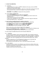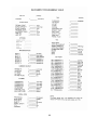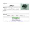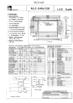
1
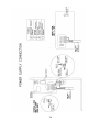
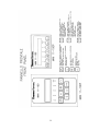
RAMSEY
WEIGHT INDICATOR/TRANSMITTER MINI 11-100P/F
MINI 11-100F
MINI 11-100P
OPERATING AND SERVICE MANUAL
DIRECTIVES
STANDARDS
CEE 93/68
CEE 89/336 (EMI-EMC)
CEE 73/23 (Low Voltage Dir.)
EMI : EN 55011 – CEI 110-6
EMC : EN 50082-1, IEC 801-2e, IEC 801-4
LVD : EN 61010-1
On request, this manual is available in ITALIAN language
File : MN-11100PF-D002A(En)
Date : December 2004
1
INDEX
1.
1.1
1.2
1.3
1.4
1.5
INTRODUCTION
General
Technical specifications
Additional OPTIONS boards
MINI line
Warranty
2. PREIMINARY CHECK
2.1 Inspecting and unpacking
2.2 Stocking
3.
3.1
3.2
3.3
3.4
3.5
INSTALLATION
Mounting
Electrical connections
Using the sensing
Supply voltage
Cleaning instrument instruction
4.
4.1
4.2
4.3
4.4
4.5
4.6
SET UP OF SCALE PARAMETERS
General
Set up
Scale capacity
Measure unit
Scale division
Sample weight
5. SCALE CALIBRATION
5.1 General
5.2 AUTO ZERO calibration
5.3 AUTO SPAN calibration with sample weights
5.4 AUTO SPAN calibration with electronic resistor
5.4.1. General
5.4.2. Accuracy
5.4.3. Equivalent computation with electronic resistor
5.4.4. AUTO SPAN calibration with electronic resistor
5.4.5. Modifying the filter factor
6.
6.1
6.2
6.3
6.4
ACCESS PROTECTION TO KEYBOARD
Protection levels
Access code
How to insert the password
Modifying the password
7.
NORMAL
7.1 Keys of normal
7.2 Use of [T] key
2
8.
8.1
8.2
8.3
8.4
8.5
ALARM
General
Alarms identification
Running options
Alarms reset
How to enable or disable an alarm function
9.
OPTIONAL FUNCTIONS
9.1
General
9.2
Options available in the standard instrument
9.2.1 Setting thresholds (1/2/3/4)
9.2.2 Setting digital input
9.2.3 Setting output
9.2.4 AZT option (auto zero tracking function)
9.2.5 TOTALIZER option
9.2.6 PEACK DET option
9.2.7 CLOCK option
9.3
Other special functions
9.3.1 Current mA OUTPUT
9.3.1.1 Modifying the mA RANGE
9.3.1.2 mA VALUE selection
9.3.1.3 mA ZERO and mA 100% selection
9.3.1.4 mA ABS VAL selection
9.3.2 Serial COMMUNICATION LINE
9.3.2.1 Set up of the serial communication line
9.4
SET UP data recording
9.5
TEST functions
10.
ADVANCED USE
11.
11.1
MAINTENANCE
Preventing maintenance
12.
SPARE PARTS LIST
3
1.
INTRODUCTION
1.1 GENERAL
This manual contains all the instructions and informations necessary for installing
and the main parameters used for scale calibration.
1.2 TECHNICAL SPECIFICATIONS
POWER SUPPLY
Voltage
115VAC – Fuse (T1A) Dimens. 5x20mm
230VAC – Fuse (T0.5A) Dimens. 5x20mm (+10% -15%)
Frequency
50/60 Hz
Power
25 V.A.
Installation Class (III)
TRANSDUCER
Power Supply of load cell 10VDC 0.5%
Minimum load
88 Ohm (6 cells max, 350 Ohm)
Input Signal
-25mV / + 25mV
Sensing Max fall of tension between the jumpers of power supply and sensing 3V
Max lenght of the connection between the load cell and 11-100 by Ramsey
standard cable, without sensing = 60m
INDICATOR ACCURACY
Resolution
32000 divisions (with input at 25mV)
Linearity
+/- 0.05 on measure range
Zero thermal drift +/- 0.5 uV/°C
Span thermal drift +/- 25 ppm/°C
MEMORY
EPROM size of 32 Kbytes
Static RAM size of 32 Kbytes
E2PROM size of 16 Kbytes for permanent data recording
Data retention in case of power off : no time limit
CPU TMPZ 84C015.AF-6 8 bit, clock frequency 12.288 MHz
INPUTS
Three digital dry contact inputs are available on the instrument. A 24VDC supply is
available for supplying the external contacts.
Available Functions :
- Set Tare
(Default on input 1)
- Reset Tare
(Default on input 2)
- Totalize Weight
- Clear Total
- Hold Weight Indication
- Clear Peack Memory
- Alarms Reset
(Default on input 3)
- Not Used
4
OUTPUTS
Four relay outputs are providede (only for the models with an N.O. contact without
tension. Each contact can drive 0.5A at 240VAC or 48vdc max.
Available Functions :
- Alarm
- Ready
- Weight Stable
- Weight has been totalized
- Total Cleared
- Threshold 1
(Default on output 1)
- Threshold 2
(Default on output 2)
- Threshold 3
(Default on output 3)
- Threshold 4
(Default on output 4)
- Not used
ENVIRONMENTAL SPECIFICATIONS
- Operating Temperature
: -10 to +50°C
- Stocking Temperature
: -20 to +70°C
- Humidity (operating & stocking) : < 90% (without condensation)
PACKAGING
Mod.11-100F Field Mounting – Renforced fiberglass housing dim. 300x250x160mm
Protection IP65 Weight 6kg
Mod.11-100P Panel Mounting – Prot. IP54, all housing IP00 Weight 1kg
WIRING
The instrument has been provided with a removable terminal block.
Maximum cable section : 1.5mmq
DISPLAY
- Type
- Characters height
- Number of characters
- Type of display
- Displaying
SIGNAL LED
- Quantity
- Functions
LCD
8mm
16
Alphanumeric
Good quality in all conditions
5
Threshold 1,2,3,4
Stable weight
Cumulative alarms
Instrument is ready
Weight totalized
Total cleared
5
CURRENT OUTPUT BOARD
- Selectable
- Maximum load
- Maximum tension on load
- Resolution
- Linearity
- Insulation
0-20mA; 4-20mA; 20-0mA; 20-4mA
500 Ohm
20VDC
12 bit (4096 divisions)
0.1 %
Galvanic, 1500 VRMS
Selectable functions :
-Net
-Gross (Default)
- Peak Weight
1.3 ADDITIONAL BOARD
SERIAL COMMUNICATION BOARD (OPTION) Cod.11-100-11
Available standars (select by jumpers)
- RS 423 (RS 232)
Null modem (ready/busy signal)
- RS 422 (RS 485)
Two wires not-isolated
- RS 422 (RS 485)
Four wires not-isolated
- Wires connection
Terminal block
- Available protocols (on request)
Ramsey PC MASTER (Standard) – Siemens 3964R – AEG Modbus
Allen Bradley DF1
SERIAL OUT (COMM MINI LINE) (OPTION)
Used only with Thermo Ramsey instruments
1.4 MINI LINE
Available model in the MINI line :
11-100P/F-RC Weight indicator with four threshold relays and insulated output 0-20 or
4-20mA.
11-100P/F-RCS Weight indicator with four threshold relays and serial output RS 423
and RS 422 and insulated output 0-20mA or 4-20mA.
1.5 WARRANTY
Thermo Fisher Ramsey warranty is given for a period of twelve mounths from the start –
up, but no longer than eighteen months from delvery, the good operation of the
delivered devices. Thermo Ramsey’s obligation under warranty is conditioned upon the
return of the defective equipment within eight days from discovery, transportation
charges prepaid to Thermo Ramsey’s workshop, with a detailed description of the
defects. Thermo Ramsey’s obligation is relevant only to repairs and/or replacements
that
Thermo Ramsey considers to be suitable for the good operation of the device according
to normal use and required as a conseguence of a fact of its own. If not specifically and
expressively defined with a written act, it will be excluded every obligation for Thermo
Ramsey on repairs or replacements and/or othr service outside its workshop.
6
2.
PRELIMINARY CHECK
2.1 INSPECTING AND UNPACKING
The instrument MINI 11-100 is a completely checked and properly packed at the
factory. To be sure of the absence of any damage due to the transport, check the
package very carefully before unpacking. In case of demages inform the carrier.
2.2 STOCKING
If the instrument has not to be immediately installed, it could be stored completely
packed in a covered place, with temperature from –20 and +70°C and relative
humidity less than 90%.The instrument is provided with a battery for data retention
without any limit of time.
3.
INSTALLATION
3.1 MOUNTING
The mounting place must be carefully selected, avoiding places where there is
vibrations, high temperature or humidity.
Model 11-100P is supplied for mounting on a covered front panel with any
inclination compared to the orizontal position.
Model 11-100F is supplied for mounting in open air. It is suggested a mounting in a
protected position against rain about, in a place with strong vibrations, it is better to
provide a mounting using non vibrating devices.
The instruments must be positioned with a suitable height in order to easily read
the display and conveniently access to thr key board.
3.2 ELECTRICAL CONNECTIONS
THE INSTRUMENT MUST BE CONNECTED WITH EQUIPMENTS
INSTALLATION CLASS (III)
Electrical connections to terminals have to be executed using flexible cable section
1.5mm max (certified by IEC227 or IEC245 standard) provided with cable terminal.
For Model 11-100F the input/output cables must be executed using press cables
(certified by standards) for the keep the instrument protection IP65.
- Load cell connection cable
: 4 x 1.5mmq, max 60m
Exceeding 60m add shielded cable 2 x 1.5mmq
for sensing connection.
- Output current cable
: Shielded cable 2 x 1.5mmq
- Output and input commands : Use 1.5mmq cable.
7
7A
WARNING
1- Don’t put signal cables near power cables
2- Connect shields only where indicated on diagrams
3- Connect ground as specified by standars
4- Never use a Megger to verify connections
3.3 USING THE SENSING
When the distance of load cell and/or cells are more than 60m use a shielded cable
2x1.5mm, connected to 13(+) and 16(-) terminal blocks (see Dwg ST11-100P/F/04).
Sensing function is used to feed back the power supply to maintain the load cell(s)
voltage equal to the desired value even in case of high cable impedance.
If the sensing has to be used, S1 and S2 jumpers on Mother board must be opened.
3.4 SUPPLY VOLTAGE
The MINI is a dual voltage instrument 115VAC or 230VAC
To select the appropiate voltage (Mod.11-100F) by the voltage selector mounted near
the main switch (see pag.7A).
(Mof.11-100P) the voltage selector (INT2) is on the AC BOARD internal instrument.
Before powering on the instrument, check if the power supply you are using is
appropiate.
Verify electrical connections and particulary check that no conductors at high tension
have been connected to terminals or signal connectors.
3.5 CLEANING INSTRUMENT INSTRUCTIONS
Conclude the instrument installation and wiring, clean residuals of rubber or wire. Is not
necessary other particulary cleaning because the instrument MOD.11-100F have
protection IP65.
IF THE INSTRUMENT IS NOT INSTALLED AND CONNECTED IN COMPLIANCE
WITH THE INDICATIONS OF THIS MANUAL, Thermo Scientific DOES NOT ASSUME
RESPONSABILITY ABOUT THE INSTRUMENT.
4. SET UP OF SCALE PARAMETERS
4.1 GENERAL
If no specific application has been requested, the instrument will be supplie with
following data :
Scale capacity
300.0 kg
Measure unit
kg
Resolution
0.1 kg
If a specific application has been requested besides this manual, our Technical
Department will deliver a documentation containing all the specific data of your scale.
4.2 SET UP
WARNING : press RUN to cancel each wrong selection
At the end of each selection push [RUN] to come back to normal running. There are
three ways to access to parameters of MINI instruments :
a) With the function key [SET UP], to modify all data of the instrument general set up.
b) With the function key [CAL] for calibrations.
c) With the function key [SET POINT], to insert the parameters of the thresholds.
The drawing in the following pages show how to enter numeric data.
8
9
10
4.3 SCALE CAPACITY
The scale capacity is expressed in engineering units and it is usually a value higher
than the working rate, compared to the nominal capacity of load cells used in the
application.
Ex : Load cell used – N°3 with max capacity 500kg – Total rate 1500kg
Working rate 500kg – Scale capacity defined at 600.0
- SELECTING THE DECIMAL POINT
Push [SET-UP] [↑] [ENTER], the display will show DECIMAL POINT; push [ENTER] to
display the value in memoty. Push [ENTER] and use [↑] key until the desired value is
displayed, then [ENTER] again. Finally press [RUN]. Select the value from the following
table :
0
1
2
0
0.0
0.00
3
4
0.000
0.0000
- SELECTING THE SCALE CAPACITY
Push [SET-UP] [↑] [ENTER] [↑] and the display will show SCALE CAPACITY ;
Push [ENTER] and the actual value of scale will be shown (300.0).
Press [ENTER] and digit 000300.0, press [ENTER].
Compose the new value 600.0 pressing [↑] [→] followed by ENTER. Press [RUN].
4.4 MEASURE UNIT
The measure unit can be selected among the following :
g kg q t LB LT
Act as follows :
Press [SET-UP] [↑] [ENTER] [↑] [↑] [↑] and MEASURE UNIT will be displayed. Press
[ENTER] and the instrument will show the memorized measure unit. Push [ENTER] and
use [↑] till you read the information you need and then press [ENTER] . Push [RUN] .
4.5 SCALE DIVISION
The scale division usually represents the instrument’s resolution and it does not exceed
3000 divisions.
Ex : Full scale 600.0 (6000 divisions)
Minimum division = 6000 : 3000 = 2 (200 g resolution)
Push [SET-UP] [↑] [ENTER] [↑] [↑] [ENTER], the display will show the scale division in
memory. Press [ENTER] and use the [↑] key until the desired value is shown, then
[ENTER] again and then [RUN].
4.6 SAMPLE WEIGHT
The calibration with sampling weights is considered as the most reliable. To perform this
kind of calibration some type-tested sample weights are needed or just use sample
masses already weighed with a scale having a high accuracy. The value is suggested to
be encluded between 40 and 80% of full scale.
Ex : defined ample weight = 420.0 kg
Press [CAL] [↑] [ENTER] ; the display will show SAMPLE WEIGHT. Press [ENTER]
and the value in memory will be displayed ; push [ENTER] again and use the [↑] and
[→] key to compose the desired value ; than [ENTER] again and [RUN].
11
5. SCALE CALIBRATION
5.1 GENERAL
A scale calibration is made of a ZERO calibration with empty scale and SPAN
calibration using a sample weight.
Before starting any kind of operation, make sure of the right mounting of load cells
and empty the scale so that the tare weight is only acting on load cell(s).
WARNING ! Press [RUN] to escape each wrong operation.
5.2 AUTO ZERO CALIBRATION
Press [CAL] [ENTER] and the display will show WAIT.
Wait till the message disappears (or press [ENTER] if you want to reduce the
calibration time).
At the end the instrument will show 0.0 kg.
Check for the repeatibility of scale : putting on and off the weight the indication
must come back to zero +/- one division.
5.3.AUTO SPAN CALIBRATION WITH SAMPLE WEIGHTS
Press the sample weight possibly in the centre of scale (ex.: 420.0 kg).
Push [CAL] [↑] and the display will show AUTO SPAN WEIGHTS ;
Push [ENTER] [↑], the display will show WEIGHTS LOADED ?
Push [ENTER] the following message will appeare : WAIT
At the end the value of the sample weights will be displayed.
Check for the repeatibility of scale : putting on and off the weight the indication must
be come back to the initial value +/- one division.
If the control gives negative results, carefully check the mechnical part.
5.4 AUTO SPAN CALIBRATION WITH ELECTRONIC RESISTOR
5.4.1 GENERAL
An instrumental calibration can be made with the MINI. Use a precision resistor to
simulate a weight on the scale when a calibration with sample weights is completely
impossible.If the instrument has been ordered for a specific application, a resistor of
the proper value will be installed inside the instrument before delivery by Thermo
Ramsey ;
its value computed by our Tech.Departement keeping count of the load cells
capacity and the scale capacity used in the application.
If the instrument has not been set, than a 49.9 Kohm resistor will be used.
5.4.2 ACCURACY
Using the electronic resistor, the calibration error in the best condition will be lower
than strictly connected to the mechanical installation and to the values of constants
inserted to obtain the equivalent load.
Usually we can have an error lower than +/- 1-2%.
12
EQUIVALENT COMPUTATION WITH ELECTRONIC RESISTOR
Use the following formula to obtain the value of equivqlent weight :
P x N x 500
CALC R CAL =
x
K
Where :
CALC R CAL
P
N
K
Rc
Rs
RC
(2 x Rs x N) + Rc
= Equivalent weight in kg
= Nominal capacity of load cell in kg
= Number of load cells in parallel
= Load cell sensibility mV/V (usually 2mV/V)
= Bridge resistor power supply side (usually 350 Ohm)
= Calibration resistor in Ohm
For some standard values of resistors see the following table :
ELECTRONIC CAL. – EQUIVALENT LOAD TABLE (Valid for load cells Mod.10-27/28/30/31A/32/9363).
ELECTRONIC F.S. OF A
EQUIVAL. % OF SIMULATED WEIGHT REFERRED TO THE TOTAL
REISTOR
SINGLE
LOAD
AMOUNT OF NOMINAL CAPACITY OF LOAD CELL
LOAD CELL
KOhm
kg
kg
1
2
3
4
6
20
50
109.1
Not Used Not Used
100
218.2
Not Used Not Used
72.7
54.5
36.36
200
436.04 Not Used Not Used
3
5
49.9
50
43.76
100
87.52
87.52
43.76
29.1
21.8
14.58
200
175.04
7
8
100
50
21.85
100
43.71
43.71
21.85
14.5
10.9
7.28
200
87.42
7
2
150
50
14.57
100
29.15
29.15
14.57
9.71
7.28
4.86
200
5.83
221
50
9.89
100
19.78
19.78
9.89
6.59
4.94
3.29
200
39.57
499
50
4.38
100
8.76
8.76
4.38
2.92
2.19
1.46
200
17.53
How to read the table :
1) Three scale capacities (commonly used) have been used.
2) If the scale capacity is multiple of one of the three values, the decimal point will be
moved right as many places as many nulls have been added to the scale capacity.
Ex.: F.S. 50 kg = 43.76 kg equivalent load
F.S. 500 kg = 437.6 kg equivalent load
Example of resistor used in a weighing system with more than one load cell.
Total scale capacity
= 10000 kg
Nominal capacity of one load cell
= 5000 kg
Number of load cells
=
3
Total capacity of load cells
= 15000 kg
(Nominal cell capacity 5000 kg x 3 load cells)
13
Now, choose a resistor to simulate a weight included between 40 and 80% of scale
capacity :
Resistor to be used
= 49.9 Kohm
Simulated weight
= 4.376 kg
% of simulated weight referred to the total capacity of load cells (15000 kg)
% of simulated weight referred to the scale capacity
= 29.17 %
= 43.76 %
5.4.3 AUTO SPAN CALIBRATION WITH ELECTRONIC REISTOR
After having calculated the value of the resistor as shown in the previous
paragraph follow these procedures :
Make sure that the scale is empty and that the indicator shows 0 +/- one division.
Otherwise proceed to AUTO ZERO calibration (see paragraph 5.2).
Enter [CAL] [↑] [↑] [ENTER] [↑] [ENTER] [ENTER] and insert the value of
equivalent weight observing the decimal point previously defined inside the
SCALE CAP function. End with [ENTER] [RUN].
Enter [CAL] [↑] [↑] [ENTER] [↑][↑] the message SCALE EMPTY ? will be
displayed. Press [ENTER], the message WAIT will be displayed for some
seconds. At the end the display will go back to the normal run.
5.4.4 MODIFYNG THE FILTER FACTOR
This function is mainly useful when the weighing system is subject to vibrations.
By altering the value of this parameter, oscillations due to yhe mechanical
vibrations can be removed.
Push [CAL] [↑] [↑][↑] [ENTER], the value of the currently defined filter will be
displayed. To alter the value push [ENTER] followed by [↑][→] to select the
desired value. Then push [ENTER] [RUN].
14
6.
ACCESS PROTECTION TO KEYBOARD
6.1 PROTECTION LEVELS
The access to keyboard of the instrument can be protected by mean of some
password. Protection levels are the following :
NONE
ACTIVE
The instrument is not protected
Process parameters cab be altered, but set up data are not accessible.
6.2 ACCESS CODE
The instrument is supplied with the default code :
20000000
6.3. PROTECTION INSERTION
Push [SET UP] [ENTER], and the word NOT ACTIVE will be displayed. Push
[ENTER] [ENTER] and use keys [↑] and [→] to enter the password (20000000 if
not already altered) and finally push [ENTER] ; at the end the word ACTIVE will be
displayed. Push [RUN].
To remove protection push [SET UP] [ENTER] and the word ACTIVE will be
displayed. Push [ENTER] [ENTER] and use keys [↑] and [→] to enter the
password (20000000 if not already altered) and finally push [ENTER] ; at the end
the word NOT ACTIVE will be diaplayed. Press [RUN].
6.3 MODIFYING THE PASSWORS
The password can be altered by using the following procedure :
Press [SET UP] [↑] [↑] [↑][↑] [↑] [↑], the word TEST will be displayed. Press
[ENTER] [ENTER] [ENTER] and use keys [↑] and [→] to edit the new password,
terminate with [ENTER].
The new password will be displayed only when the protection is not active.
WARNING !
Before enteringa new password, be sure to make a written copy of it and to store it
in a safe place. If the new password will be forgotten, the only way to restore acces
to the set up data will be to send the instrument to Thermo Ramsey for service.
15
7.
NORMAL USE
7.1 KEYS OF NORMAL USE
The functions which can be used during normal running are the following :
[RUN] key
Always returns to the display of the weight. If used while the
weight. If used while the net weight is displayed, will open
the SET UP menu.
[CAL] key
Access the calibration functions
[↑] key
Select, NET LOAD, GROSS LOAD, TARE OR ALARMS
[SET POINT] key
Allow to set the thresholds.
[-T-] key
Set and reset tare. When some tare has been cleared, the
symbol T is displayed on the left side of the screen.
7.2 Use of [-T-] key
-
This function is used for many applications, the most common are :
Clearing the weight of the possible left over on the weight hopper
Clearing the weight of the container of material that must be weighted.
To activated this function press [-T-] and the indicator will be set to zero.
To show that the function is active, the symbol T will appear on the left side of the
display.
WARNING ! This key is always enable. If pressed while the scale is not empty, the
indicator will istantaneously display zero.
To go back to the previus function press [-T-].
16
8.
ALARMS
8.1 GENERALS
Inside the program of the MINI some control functions are included, which allow to
verify the correct working of the instruemnt, of the load cells and of the weighing
process.
8.2 ALARMS IDENTIFICATION
When the instrument generates an alarm, the cause is displayed alternatively to
the weight indication. To identify the cause, see the following table :
THRESHOLD 1
Weight exceeds threshold Nr.1
THRESHOLD 2
Weight exceeds threshold Nr.2
THRESHOLD 3
Weight exceeds threshold Nr.3
THRESHOLD 4
Weight exceeds threshold Nr.4
COLD START
Set up data were lost during power off
LOAD CELL FAIL - The power supply to the load cell(s) could be interrupted
- Possible short circuit of the power cables of the load cell(s)
- Possible short circuit of the shield cable with one of the power
cable.
MAX ZERO OCC The outo zero tracking function has compensated all the
possible error of zero according to the specified limit.
8.3 RUNNING OPTIONS
Each alarm can be set as follows :
- NONE
- ALARM
no action
alarm, acts on alarm cumulative output
8.4 ALARMS RESET
To clear the alarm follow the procedure below :
Press [↑], the display will show : ALARMS ;
Press [ENTER], the display will show the pending alarm ;
Press [ENTER], until the display will show the message : NO ALARMS and then
press [RUN].
Only alarms that are actually not existing will be reset. If the condition that caused
the alarm message is still existing, the alarm will not be cleared.
8.5 HOW TO ENABLE OR DISABLE AN ALARM FUNCTION
To enable or disable an alarm act as follows :
Press [SET UP] [↑] [↑] [↑] [↑] [↑] [ENTER]. The description of the first alarm will
be displayed : THRESHOLD 1.
Press [↑] until the desired alarm is displayed.
Press [ENTER] [ENTER] and use the [↑] key to properly set the alarm code, atthe
end press [ENTER] [RUN].
17
9.
OPTIONAL FUNCTIONS
9.1 GENERAL
In addition to the normal weight indication, the instrument provides some auxiliary
functions making it suitable for simple automation process.Adding the SERIAL
COMMUNICATION BOARD (OPTIONAL) a serial signal can be transmetted to
supervisor or control instruments, or printer.
Optional boards are usually installed by Thermo Ramsey personnel only.
9.2 OPTIONS AVAILABLE IN STANDARD INSTRUMENT
The following list contains options that are already implemented in the standard
instrument and that can be recalled without installing additional hardware.
9.2.1 SETTING THRESHOLDS (THRESHOLD 1/2/3/4)
The instrument provides four thresholds, each having the following features :
- SET THRESHOLD Nr.
Weight over (or under) which to take action
- VAR THRESHOLD Nr. Variable on which the threshold is calculated. Can be
the NET WEIGHT or the GROSS WEIGHT.
- TYPE THRESHOLD Nr. Can be :
HIGH The relay is activated when the weight is over
the set point.
LOW The relay is activated when the weight is lower
The set point.
- HYSTERESIS THR. Nr. Hysteresis used before restoring the normal status of
the relay. The relay is released when :
HIGH The weight is lower that the set point minus the
hysteresis.
LOW The weight is higher that the set point plus the
hysteresis.
Examples :
THRESHOLD 1 = 300 kg
VAR. THRESHOLD 1 = NET WEIGHT
TYPE THRESHOLD 1 = HIGH
HYST THRESHOLD 1 = 27 kg
The relay is excited when the net weight is higher than 300 kg and is released
when the net weight is lower than 273 kg.
THRESHOLD 1 = 20 kg
VAR. THRESHOLD 1 = GROSS WEIGHT
TYPE THRESHOLD 1 = LOW
HYST THRESHOLD 1 = 3 kg
The relay is excited when the gross weight is lower than 20 kg and is released
when the gross weight is higher than 23 kg.
To alter parameters act as follows :
Press [SET POINT] followed by [↑] as many times as required to display the
desired parameter. Then press [ENTER] and [↑] [→] until the displayed value is
the desired one. At the end press [ENTER] [RUN].
The contacts of the output relayes are available on the rear terminals.
18
9.2.2 DIGITAL INPUTS SETTING
The instrument can be connected to three dry contacts. One of the following
functions can be assigned to each input :
SET TARE
Copy gross weight into the tare memory. Net weight is set to zero
RESET TARE Clear tare memory. Net weight is set equal to gross weight.
UPDATE TOTAL Add net weight to the total.
CLEAR TOTAL Set the total to zero.
HOLD WEIGHT Stop updating the displayed weight. Net and gross weights are
frozen.
CLEAR PEAK
The memory containing the “pesk” weight is cleared.
NOT USED
The input is not used.
CLEAR ALARMS Reset all pending alarms.
9.2.3 DIGITAL OUTPUT SETTING
The instrument has four relays that provide four dry contacts on the rear
terminals block. One of the following functions can be assigned to each output :
THRESHOLD 1
High or low threshold Nr.1
THRESHOLD 2
High or low threshold Nr.2
THRESHOLD 3
High or low threshold Nr.3
THRESHOLD 4
High or low threshold Nr.4
NOT USED
The output is not used
ALARM
Relay is off when an alarm occurs
INSTRUMENT READY
Relay is on when the instrument is powered on, not
in alarm condition, not in calibration
WEIGHT STABLE
Relay is on when the weight is stable (weight
Indication varies less than one division)
TOTAL UPDATED
The total has been updated adding the net weight. A
pulse is generated on this output.
TOTAL CLEARED
The total has been cleared. A pulse is generated on
this output.
9.2.4 AZT OPTION (AUTO ZERO TRACKING FUNCTION)
This function is used to keep the net weight equal to zero, if the are variations are
contained within a predefined band.
To enable the function press [SET UP] [↑] [ENTER] [↑] [↑] [↑] [↑] , the display
will indicate AZT. Press [ENTER] [ENTER] and use keys [↑] and [→] to enter
the percentage value of the AUTO ZERO TRACKING BAND with reference to
the scale capacity. End with [ENTER].
Press [↑] the display will show AZT TIME.Press [ENTER][ENTER] and use keys
[↑] and [→] to enter thr percentage value of the AUTO ZERO TRCKING TIME
used to average the weight before zeroing. End with [ENTER].
Press [↑] the display will show AZT LIMIT.Press [ENTER][ENTER] and use keys
[↑] and [→] to enter the percentage value of the AUTO ZERO TRACKING
LIMIT, with reference to the calibration zero. End with [ENTER] [RUN].
Example :
SCALE CAPACITY = 500 kg
AUTO ZERO TRACK = 2.0 %
TIME AZT = 5 sec
LIMIT AZT = 5.0 %
Weights within plus and minus 1.0 kg (equal to 2% 0f 500 kg) will be zeroed but
up to a maximum of plus minus 2.5 kg (equal to 5% of 500 kg).
The weight will ahve to stay stable for a least 5 sec. Before the auto zeroing can
take place.
19
9.2.5 TOTALIZER (OPTION)
This option is used to know the amount of material weighed with the scale. If the
scale is used for a number of weighings and if the number and the total amount
has to be recordered, set the instrument as follows :
Press [SET UP] [↑][↑], the message OPTIONS will be displayed; press [ENTER]
[↑] [↑] [↑], the message TOTALIZER will be displayed. Press [ENTER] [ENTER]
and use [↑] to select YES. End with [ENTER] [RUN].
To use the totalizer option it is suggested to select one of the digital inputs for the
UPDATE TOTAL function (see par. 9.2.2). Each time the input is closed, the
instrument will add the net weight to the totalization register, and the counter
register will be incremented by one.
To display the two register (total and counter) just press [↑] while the instrument
is displaying the net weight until the following is displayed :
TOTAL
COUNTER
pressing [ENTER] the accumulated total is displayed
pressing [ENTER] the number of totalizations is displayed
To clear register act as follow :
Press [↑] until the TOTAL is displayed. Press [ENTER] [ENTER] and 0 will be
displayed. To confirm zeroing press [ENTER]. To alter the value press [↑] and
[→]; to skip zeroing (saving the old value) press [RUN].
A digital input can also be programmed to clear the totalization register from
remote (9.2.2).
9.2.6 PEACK DET (OPTION)
Use the function to display and save a quick transient signal.
Follow this procedure to enable the function :
Press [SET UP] [↑] [↑], the message OPTIONS will be displayed. Press
[ENTER] [↑], the message PEACK SENSOR will be displayed. Press
[ENTER] and then use the [↑] key to select YES. End with [ENTER] [RUN].
The displayed weight will than not be the net weight, but the highest weight after
the last clearing (peack weight).
The memory is cleared using a digital input that must be programmed for the
CLEAR PEACK WEIGHT (see 9.2.2).
20
9.2.7 CLOCK (OPTION)
This option is used to configure the CLOCK component installed on the Serial
Communication Board
Press [SET UP] [↑] [↑], the messagge OPTION will be displayed;
Press [ENTER] [↑] [↑] [↑] [↑], the message CLOCK will be displayed.
Press [ENTER] and then use the [↑] key to select one of these choices
- MM 58174
- MM 58274
- NOT USED
End with [ENTER] [RUN]
to identify the installed component read the reported code on the white label
attached over the integrated circuit, installed on the left side of the battery (top
view with terminals toward the top).
9.3 OTHER SPECIAL FUNCTIONS
Here follows a list of the special functions inside the instrument.
9.3.1 CURRENT (mA) OUTPUT
If the instrument was already set by the factory, after installing the follow this
procedure :
Press [SET UP] [↑] [↑], the message OPTIONS will be displayed. Press [ENTER],
the message CURRENT OUTPUT will be displayed; press [ENTER] [ENTER] and
use the [↑] key to select YES. End with [ENTER] [RUN].
9.3.1.1
MODIFYING mA RANGE
The instrument is pre-set to the 4-20 mA operating range.
Other available ranges are : 0-20mA; 20-0mA; 20-4mA.
Close the jumper J1 on the optional board or insert a resistance of 500 Ohm
on the terminal block 29 and 30 to select the output with 0-10V.
To select a range different from the default one, act as follows :
Press [SET UP] [↑] [↑] [↑] [↑], the message CURRENT OUTPUT will be
displayed. Press [ENTER], the message mA RANGE will be displayed; press
[ENTER] [ENTER] and use the [↑] key to select the desired range. End with
[ENTER] [RUN].
9.3.1.2
mA VALUE SELECTION
The mA output can transmit one of the following variables :
GROSS
The current output is proportional to the gross weight and is
not affected by the [-T-] key.
NET
The current output is a proportional to the net weight and it
is set to the minimum value when the [-T-] key is pressed.
PEACK WEIGHT The current output is proportional to the peack weight in
memory.
21
To select the current referred to the peack weight, act as follows :
Press [SET UP] [↑] [↑] [↑] [↑], the message CURRENT OUTPUT will be
displayed. Press [ENTER] [↑], the message mA VALUE will be displayed;
press [ENTER] [ENTER] and use the [↑] key to select the desired variable.
End with [ENTER] [RUN].
9.3.1.3
mA ZERO AND mA 100% SELECTION
Special function to use the 4-20mA signal within a defined range:
mA ZERO
mA 100%
The percentage of the trasmitted variable corresponding to
the minimum signal.
The percentage of the trasmitted variable corresponding to
the maximum signal.
Example: To transmit a 4-20mA signal in a range from 20% to 80% of the
scale capacity.
mA ZERO :
mA 100% :
set 20%
set 80%
By default the output signal is trasmitted on all the work range of the scale so
the standard set up is the following :
mA ZERO :
mA 100% :
9.3.1.4
set 0%
set 100%
mA ABS VAL SELECTION
The mA output can be set for a charging or discharging batch.
CHARGE BATCH
mA is proportional to the material loaded in the hopper.
DISCHARGE BATCH Hopper has been filled up and SET TARA has been
made [-T-], the mA signal is proportional to the material
taken out from the hopper.
For uses with charge batch select
: mA ABS VAL
For uses with discharge batch select : mA ABS VAL
=
=
NO
YES
To make the selection press [SET UP] [↑] [↑] [↑] [↑], the message
CURRENT OUTPUT will be displayed. Press [ENTER] [↑] [↑] [↑] [↑], the
message mA ABS VAL will be displayed ; press [ENTER] [ENTER] and use
the [↑] key to select the desired value. End with [ENTER] [RUN].
9.3.2 SERIAL COMMUNICATION LINE
(AVAILABLE with OPTION Serial Communication Board)
The serial communication line allows to connect the instrument to computers and
PLC’s. The line can be configured as RS 423 or RS 422.
22
9.3.2.1
SET UP OF THE SERIAL COMMUNICATION LINE
The standard instrument is supplied with :
- RS 423
- CTS (not checked)
To set the serial output, select some jumpers on the serial board
Cod. 11-100-11, looking at the following table.
OUTPUT
RS 423 (RS 232)
RS 422 (RS 485)
YES
NO
(A) Open
(A) Closed
JUMPER (J1)
(B) Closed
(B) Open
TERMINATOR SELECTION (J2)
(A) Open
(B) Closed
(A) Closed (B) Open
Access SET UP data, press [↑] [↑], the message OPTION will be displayed.
Press [ENTER] and [↑] and the message SERIAL LINE will be displayed.
Press [ENTER] [ENTER] [↑] and select YES, end with [↑] key select the
SERIAL COMMUNICATION function. Press [ENTER] [ENTER] and select
the desired function by [↑]. End with [ENTER].
PPROTOCOL can be selected between the following :
- PC MASTER, Ramsey standard
- 3964R, Siemens standard
- DF1, Allen Bradley standard
- MODBUS, AEG standard
22
Then with [↑] set the communication data.
LINE SPEED
STOP BITS
PARITY
WORD LENGHT
can be 300, 600, 1200, 2400, 4800, 9600, 19200, 38400 baud
can be 1 or 2
can be EVEN, ODD, NONE
can be 7 or 8
The communication protocols are described on a separate manual.
9.4 SET UP DATA RECORDING
SET UP parameters must be defined according to specific application. The table in the
next page, allows to record all data you have inserted. The values in brackets are
initialization data : in case of general zeroing (COLD START) the values in brackets will
appear on the display. In case of loss of data, due to failure or special maintenance, the
instrument will be quickly restored to its normal functions.
23
9.5 TEST FUNCTIONS
The instrument MINI 11-100 is equipped with some test functions to detect possible
failure.
PASSWORD On password can be installed to access the instrument.
A/D GROSS Reading of the number, between 0 and 32000 divisions, calculated by
the A/D converter.
A/D NET
Reading of the number, less the tare (zero), calculated by the A/D
converter. This value is included between o and 32000 divisions
(the signal is not filtered).
LOAD CELL SIGN. Reading of the load cell signal. This value must be included
between 0 and 30mV.
E2PROM
Check if the writing is right. Usually 0 will be displayed.
VERSION
The version of the installed program is displayed (31.xx.xx.xx).
MEMORY TEST
Check the writing on RAM is right. Press [ENTER] to start
the memory test. If it will be positive, the message RAM OK
will be displayed, on the contrary RAM ERROR.
INPUT TEST Test of the three digital inputs.
Open contact = 0
Closed contact = 1
OUTPUT TEST
Test of the four digital outputs. Use [↑] and [→] to enable / disable
the outputs.
LAMP TEST Test of the display and leds on the frontal panel.
FORCE VAL Force a signal of current output. Use key [↑] and [→] to set a value
Referred to the scale capacity.
10. ADVANCED USE
To use the advanced functions of the instrument refer to Service Manual. For those
companies who intend to train their personnel, Thermo Ramsey organizes some
individual and group courses of instruction. For information, contact Service
Departement.
11. MAINTENANCE
11.1 PREVENTING MAINTENANCE
No preventing maintenance is required. Periodical verifications of calibration could
be needed for mechanical reasons related to the weighing system (tare
modification, supports movements, etc.).
The interval between calibration verifications depends upon the use and the
required accuracy.
We suggest starting to check for zero and span once a day with simulated method.
Then use longer intervals up to the maximum that is compatible with the required
accuracy.
24
12. SPARE PART LIST
Thermo Electron supplies the following spare parts :
MINI 11-100F
Mother Board CPU
Supply and Relays Chassis
Serial Out Board
Display Board
Key Board
Set N°10 fuse 1A 5x20 supply 115V
Set N°10 fuse 0.5A 5x20 supply 230V
MINI 11-100P
Mother Board CPU
Supply and Relays Chassis
Serial Out Board
Key and Display group
Set N°10 fuse 1A 5x20 supply 115V
Set N°10 fuse 0.5a 5x20 supply 230V
25
26
27
28
29
30
31
32
33