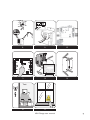
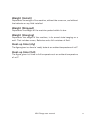
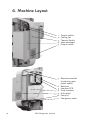
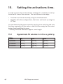
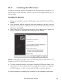
1
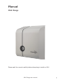
VALI Range Manual installation and operating instruction Every effort has been made to ensure that the contents of this manual are correct. MSS Professional A/S does not accept any liability for loss or damage caused or alleged to be caused directly or indirectly by this manual. The contents of the manual may be subject to change without notice. MSS Professional A/S makes no warranty of any kind with regards to this material. © 2009 MSS Professional Reproduction in any matter whatsoever without the written permission of MSS Professional A/S is strictly forbidden. READ AND SAVE THESE INSTRUCTIONS MSS Professional A/S Brunbjergvej 6 8240 Risskov Denmark Phone +45 7217 0011 Fax +45 8617 0055 [email protected] www.smokecloak.com 2 VALI Range user manual Manual VALI Range Please read this manual carefully before attempting to install an VALI. VALI Range user manual 3 Conventions The following symbols are used in this manual to help you install the SmokeCloak system correctly and safely. Note Gives useful advice or suggestions to enhance the performance of the SmokeCloak system. Important Indicates important information that is critical for the correct use of your products and must always be read carefully. It is essential that only genuine SmokeCloak fluid is used. Damage to the equipment and possible health hazard is likely if incorrect fluid is used. The warranty on all of the equipment will also be void. Under no circumstances should the on board power supplies of the SmokeCloak (terminals 1, 6, 19, and 20) be linked to any other 3rd party equipment e.g. alarm panels, additional power supplies, etc. as this could cause unexpected faults within the machines 4 VALI Range user manual Contents PRODUCT OVERVIEW.......... 6 13.Connection Details.......29 Status LEDS............................ 29 1.IN THE BOX.........................7 Interface board Connections.......30 Outputs...................................42 2. QUICK START GUIDE............ 8 Test button wiring.....................44 3. SPECIFICATIONS............... 10 14. CLOAKSENSOR..................46 Installation...............................46 4. MACHINE LAYOUT.............12 Locations to avoid.....................47 5. INSTALLATION....................13 15. SETTING THE TIMER...........48 16. PREPARATION FOR FINAL TEST.......................50 Requirements............................13 Torque setting.......................... 14 Horizontal Installation................ 14 Mounting the machine................15 Wall Installation.........................16 17. MAINTENANCE ..................51 6.Changing the Nozzle.....17 18. PC-Tool.............................. 52 Updating the registry................. 52 7.Installing the Nozzle ..... Installing the VALI drivers.......... 53 for the first time.......... 18 Configuration software...............54 8. FLUID.................................19 19.Using the software...... 55 Installing the Fluid Bottle............19 Connecting to the VALI.............. 55 9.Priming the Machine..... 22 20. ACCESSORIES................... 62 Fluid FL600-V........................... 62 10. BATTERIES......................... 23 Cloaksensor CS07A................... 63 Installing the Batteries............... 23 11. WIRING UP THE MACHINE... 27 Wiring the mains feed............... 27 Wiring the batteries................... 27 Strobe IPL3000.........................64 Sounder IPA 125........................ 65 Voice Module...........................66 Batteries.................................. 67 12. INTERFACE BOARD............28 Layout.....................................28 Contents 5 Product Overview Strong Background The VALI range is build on more than 20 years of experience in the fog security industry. Powerful The addition of the V5, V10 and V20 to the SmokeCloak range offers a new level of raw power in terms of the amount of output these units are able to produce. Whilst also being the slimmest and sleekest machines to be produced to date, this makes them perfect for any application, be that an office requiring a professional yet discreet look, or a retail outlet requiring lightning quick response time and maximum protection. Simplicity From the new ‘engineer friendly’ mounting system to the onboard USB interface – the design of the VALI range is focused on ease of installation, ease of use, monitoring for the customer and greater serviceability. Versatility As well as the mix of explosive output and sleek looks, the VALI range can also be customized to suit any installation. The inclusion of a new interchangeable nozzle system means the machine is far more versatile in terms of where it can be positioned within a room and also the type of coverage it can provide within that space. 6 VALI Range user manual 1. In The Box Before attempting to install the machine it is advisable to ensure that you have all the required components. Upon opening your VALI box you should find: x1 off VALI unit (V5/V10/V20) Check serial labels to ensure the correct voltage x1 off Grille Plate Assembly x1 off Installation Bracket x1 off Manual pack Manual Warning stickers CD Rom End user guide x1 off Accessory Pack Straight nozzle insert 30 degree nozzle insert 3-way nozzle insert Circlip (x2 off) M4x10 black taptite screws (x4 off) M6x12 black pozi screws (x4 off) x1 off Cloaksensor (CS07A) In addition to the above items you will also need 2x 1.2 Ah 12 V batteries. MSS Professional A/S recommends FIAMM or similar quality. In addition, the following specialist tools will also be required: Internal Circlip Pliers (20 mm) VALI Range user manual 7 2. Quick Start Guide To quickly prepare and fire your unit, the following steps should be taken. For more detail on anything below, see the full guide provided. Max 3 m Max 2,5 m 1 8 2 3 4 5 6 7 VALI Range user manual 8 9 10 11 12 13 Test 14 15 VALI Range user manual 9 3. Specification 10 V5 V10 V20 Dimensions (mm) 438 x 340 x 176 438 x 340 x 176 488 x 340 x 176 Weight (install) 11.65 kg 11.65 kg 14.1 kg Weight (shipped) 21.2 kg + box 21.2 kg + box 24.3 kg + box Weight (hanging) 20.15 kg 20.15 kg 23.15 kg Performance 210 m3 in 30 s 405 m3 in 30 s 600 m3 in 30 s Reaction Time 0.5 s 0.5 s 0.5 s Fluid Consumption 90 ml in 30 s 175 ml in 30 s 260 ml in 30 s Standard Colour RAL 7035 / RAL 7024 RAL 7035 / RAL 7024 RAL 7035 / RAL 7024 Mounting Vertical or Horizontal Vertical or Horizontal Vertical or Horizontal Fluid Reservoir 1.7 L 1.7 L 1.7 L Heat up Time (Rdy) 9 minutes (110 V) 10 minutes, 30 s (208) 9 minutes (230 V) 9 minutes (110 V) 10 minutes, 45 s (208) 9 minutes (230 V) 10 minutes (110 V) 9 minutes (230 V) 15 minutes (110 V) Heat up Time (Full) 14 minutes (110 V) 17 minutes (208 V) 14 minutes (230 V) 16 minutes 110 V) 19 minutes, 20 s (208 V) 16 minutes (230 V) 11 minutes (208) 15minutes 45 s (208 V) 13 minutes (230 V) Timer Adjustable Adjustable Adjustable Voltage 230 V, 208 V, 110 V Available 230 V, 208 V, 110 V Available 230 V, 208 V, 110 V Available Heat Power 110 V 2 x 700 W 2 x 700 W 2 x 850 W Heat Power 208/230 V 2 x 700 W 2 x 700 W 2 x 950 W Power Consumption at 230 V (max) 1.45 KW 1.45 KW 2.0 KW Power Consumption at 208 V (max) 1.2 KW 1.2 KW 1.65 KW Power Consumption at 110 V (max) 1.45 KW 1.45 KW 1.8 KW Standby Power Consumption 78 W 85 W 105 W Current Draw at 230 V (max) 6.4 A 6.4 A 8.85 A Current Draw at 208 V (max) 5.8 A 5.8 A 7.8 A Current Draw at 110 V (max) 12.1 A 12.1 A 15 A Pumps x1 24 V solidstate, variable output, x1 24 V solidstate, variable output, x2 24 V solidstate, variable output, VALI Range user manual Weight (Install) Represents the weight of the machine, without the covers on, and without the batteries or any fluid installed. Weight (Shipped) Represents the weight of the machine packed within its box Weight (Hanging) Represents the weight of the machine, in its armed state hanging on a wall. That includes covers, Batteries and a full container of fluid. Heat-up time (rdy) The figure given is a time to ‘ready’ state at an ambient temperature of 20°C Heat-up time (full) The figure given is a time to full temperature at an ambient temperature of 20°C VALI Range user manual 11 4. Machine Layout 1.Tamper switch 2.Cooling fan 3.Thermal Switch 4. Heat exchanger 5.Output nozzle 5.Electronics module (containing main power board) 6. Batteries 7.Interface PCB 8. Fluid container 9.Grille plate 10.Pump (s) 11.Changeover valve 12 VALI Range user manual 5. Installation 5.1 Prior to Installation Requirements - UK installations In the UK the installation must be carried out to conform with British Standard BS7939:1999 for the installation and maintenance of Smoke Security Devices. BS7939 installation requirements summary The installer should, prior to the installation liaise with the local fire authority to ensure that there are no local restrictions in force. The installation should only be conducted by trained personnel who have passed a written test. The SmokeCloak should be configured so that it can only activate when the burglar alarm is set. The SmokeCloak must not be configured to form a “man-trap” i.e. activate to cut off a means of escape. The SmokeCloak should not be installed to cover escape routes and staircases of areas that are still occupied. Care should be given not to fog joint access areas of adjoining premises. In multi-occupancy buildings or in large sites with internally SmokeCloak protected areas, the vapour must be confined to those areas and must not be allowed to infringe into public or open areas. Care must be given to automatic fire alarm systems so as not to cause unwanted or false activations. Consideration should be given to audible and visual indication of SmokeCloak activation. The installer should inform the fire brigade, police and monitoring station of the installation prior to commissioning. A full test activation should be performed as part of the installation. For installations outside the UK, please adhere to local standards VALI Range user manual 13 5.2 Position The VALI can be installed vertically for wall mounting, or alternatively mounted horizontally for ceiling installations. The VALI’s fluid container design means that no modifications are required when changing between horizontal and vertical mountings. This equipment should only be installed and connected to the supply by a suitably skilled and competent person. This apparatus must be earthed. Connections are made to a plug-in terminal block. The SmokeCloak should be connected to a standard 13 amp fused spur. Flexible mains cables must have a minimum crosssection area of 1.25 mm2 (and must be BASEC approved in the UK). Ensure that the protective earth conductor is made longer than the live and neutral conductors, and that the cable clamp grips both the sheath and insulation. 5.3 Torque Settings In order to avoid damaging some of the internal fixings and components it is important that the specified torque settings are not exceeded. Unless otherwise stated within this manual, the maximum torque to be used for all fixings within the VALI machine should be 1.2 Nm 14 VALI Range user manual 5.4 Mounting the machine 1.Screw the installation bracket to the wall/ceiling Horizontal: 6 mm threaded hanging bars should be used. These should be located on the slots at the ends of the hanging bracket and tightly fastened into position. 2.Ensure that the cables are routed through the bracket and fed through the grommet bushes. The access hole in the installation bracket should allow the cables to be easily fed into position. 3.Offer the machine into place and push back until you feel it slide into position. 4.Use the 4 fixing points to secure the machine in position. 5.Follow the instructions for wiring and connecting the machine. VALI Range user manual 15 Wall mounting: It is not recommended to install the machine in excess of 2.5 m high, otherwise the smoke coverage near the floor may be compromised. Horizontal mounting: Ensure the machine is no more than 3 m above the floor, otherwise smoke dispersal may be compromised. 16 VALI Range user manual 6. Choosing and changing the nozzle VALI will come as standard with no nozzle installed. It is the job of the installer to assess, install and test which of the three nozzles supplied should be used in order to ensure that the machine is best suited to the particular installation. Straight Nozzle Provides a single powerful burst directed perpendicular to the front of the machine. 3-Way Nozzle Provides a distributed effect. 75% of the effect is fired through the outer 2 holes to cover an area close to the machine (ideal for smaller rooms) The remaining effect is fired through the central hole giving a good mix of throw and distribution. Note: by changing the orientation of the nozzle the effect can be projected in varying directions 30-Degree Nozzle Provides a single powerful burst directed at 30° to the front plane of the machine. Note: by changing the orientation of the nozzle the effect can be projected in varying directions. VALI Range user manual 17 7. Installing the correct nozzle for the first time: 1.By making a quick assessment of the area to be protected by the SmokeCloak, decide which of the three available standard nozzles should be used. You can see examples on the previous page. 2.Remove the warning label 3.Take the required nozzle and install it within the nozzle body. 4.Take the circlip provided and using a pair of internal circlip pliers, engage the circlip into the ridge running around the inside of the nozzle body. It is crucial this is installed correctly in order to retain the nozzle safely. 5.Once the nozzle is correctly engaged, install the grille plate using the 4x black taptite screws found in the accessory pack. It is important that the suggested torque settings are adhered to. 6.Follow the test procedure. Take great caution when changing the nozzle, it becomes extremely hot as the machine heats up. Do not attempt to handle the nozzle once the machine has heated up to temperature. Following any installation or changing of the nozzle – Ensure that a test firing is carried out to ensure that the new nozzle has been correctly and safely installed. When performing this first test firing insure that the grille plate is installed correctly and everybody is standing back from the front of the machine. 18 VALI Range user manual 8. Fluid FL600-V fluid is used to generate the vapour cloud. This glycol based fluid is made to a special formula, which is designed to produce 40% obscuration of light at 40 cm with minimum condensation. 8.1 Installing the Fluid Bottle Your VALI product will be supplied with a full fluid container installed. It will arrive with a sealed travel cap installed. The following steps should be taken in order to correctly install the fluid bottle and the fluid sensing unit. 1.Remove the fluid bottle from the machine, 2.Slide the fluid sensor assembly inside the bottle – screw down the cap tightly to create a seal. 3.The bottle can then be slid back into position within the machine. 4.Connect both the fluid sensor wire and the quick release fluid line coupler ensuring that it ‘snaps’ firmly back into its engaged position. 5.It is recommended that following any installation of the bottle a short test fire is carried out to ensure the fluid line has been correctly reinstalled and to re-prime the fluid feed lines. VALI Range user manual 19 Click 20 VALI Range user manual It is essential that only genuine SmokeCloak fluid is used. Damage to the equipment and a possible health hazard is likely if incorrect fluid is used. The warranty on all of the equipment will also be void 8.2 Changing the Fluid As part of the maintenance of the VALI it is essential that the fluid is replaced annually to ensure that the quality of the effect produced is maintained at the desired level. In order to change the fluid follow the same instructions in the previous section for installing the fluid bottle, once removed. Discard the empty fluid container and replace with a new full bottle of fluid. The fluid should be changed (not topped up) at least once a year. Do not mix batches of fluid. (Batch number is printed on the front of the bottle). Take care not to overfill the bottle – it could potentially lead to electric shock. VALI Range user manual 21 9. Priming the machine Following either the initial installation of the fluid bottle or following changing of the bottle it is essential that a short test firing is carried out to ensure that the fluid feed pipes are correctly primed. Failure to follow this procedure will lead to delayed response time the first time the machine is fired following the service or, more significantly, a failure to observe a connection fault incurred during the installation or re-installation of the fluid bottle. This should be done using the manual test button with the machine in service mode. See 13.6.4. During the test firing, observe the output to ensure the level is satisfactory before leaving the machine. If the level appears to be below what would normally be expected of the machine, repeat the test process. If after 3 test cycles the output still appears to be below the ‘regular’ level of effect check the following: 1.The quick release coupler between the fluid line and the bottle cap was correctly re-engaged. 2.The fluid cap was correctly re-engaged into the bottle, that the fluid feed pipe wasn’t trapped in any way, and that the cap was firmly screwed back into position. 3.If there still appears to be a problem contact your supplier. 22 VALI Range user manual 10. Batteries 10.1 To install the batteries: 1.Remove the two M4 screws that retain the battery bracket. 2.Place the batteries into the bracket as shown to the left. 3.Follow the instructions for wiring up the batteries. The final two connections onto the power board should NOT be made at this point. 4.The bracket, complete with batteries should then be slid back into position behind the interface board. 5.The battery assembly should be re-secured using the M4 screws provided. 6.Complete the wiring by making the connections to the power board. Carefully observe the polarity. VALI Range user manual 23 Battery bracket X2off 1.2aH 12V Batteries Electronics module Interface Board Battery Module 24 VALI Range user manual 10.2 Wiring the batteries Once the batteries are installed within the bracket provided they must then be wired together in series and connected to the power board. Follow the instructions below – The battery loom provided should be used. It will contain a single blue wire used for linking the batteries in series and in addition a red and a black wire for connecting the wires back to the power board. The red wire should be terminated at PL22 on the power board and the black wire at PL21. The terminals labeled + with the red wire, and - with the black wire. The battery backup system provides power for the control electronics and pumps when mains electricity is removed. The batteries are installed on a dedicated bracket which is found behind the interface board: VALI Range user manual 25 The standard backup system does not provide power for the heater. The insulation is designed to retain sufficient heat in the aluminium heat exchanger assembly. The SmokeCloak must have the batteries installed, even when operating from the mains, The battery backup system requires 24 V d.c. - it is necessary to fit two 12 V 1.2 Ah batteries in series in the SmokeCloak. Do not use larger than 1.2 Ah capacity batteries to prevent fuse failure due to excessive charging current. Please note that the temperature inside the SmokeCloak can exceed 40 degrees depending on the ambient temperature - the batteries must be able to withstand this temperature under charging. Take care with polarity. The SmokeCloak is protected with an auto-reset fuse to safeguard against reverse polarity connection of the batteries. The LEDs on the interface board will give indication of correctly installed fluid and batteries. PCB damage due to incorrectly fitted/sized batteries is not covered under warranty. MSS Professional strongly recommends that Fiamm 1.2 Ah batteries or similar quality are fitted. These can be purchased from MSS through your distributor. 26 VALI Range user manual 11. Wiring up the Machine The mains power and low voltage control signals are clamped to the installation bracket using the cable clamps provided. The cables should be routed through the cable guide provided on the back face of the bracket, then fed through the cable clamps and terminated with the supplied plugs. Lead lengths between the clamps and plugs should be a maximum of 30 cm. 11.1 Wiring the mains feed Remove the mains plug from the electronics module and fit to the flexible mains cable that has been fed through the cable grommets. Plug mains lead back into motherboard. Observe connection polarity (see below). 110 V / 208 V VERSIONS The terminal block situated on the main power pcb is intended to be used with NRTL (Nationally Recognised Testing Laboratory) listed pressure terminal connectors. These must be fitted on the end of the conductors before attachment to the wiring terminals of the terminal block in order to maintain the machines ETL approval. If in doubt, contact your supplier. VALI Range user manual 27 12. Interface board 1 2 3 4 7 9 10 13 8 12 5 1.SPI connection 2.Programming socket 3.LED output 4.PL1 5.PL2 6.PL3 7.PL4 8.Sounder 9.Switch 1 10.Switch 2 12.USB Interface 13.Test button connector 28 VALI Range user manual 6 13. Connection Details 13.1 Status LEDS LEDS LD LD LD LD LD LD LD LD LD LD 1 2 3 4 5 6 7 8 9 10 Battery (on - ok) Mains (on - ok) System ready (on - ready) Heater (on - heating) Temperature fault (on - fault) Low fluid (on ok, off fault) No fluid (on ok, off fault) System (on - ok) System active (on - active) Backstop active (on - active) VALI Range user manual 29 13.2 Interface Board Connections PL 1 Terminal Terminal Terminal Terminal Terminal Terminal 1 2 3 4 5 6 12 Volts PIR Cloaksensor Case open, Log signal Signal 0 Volts 0 Volts PL 2 Terminal Terminal Terminal Terminal Terminal Terminal 7 8 9 10 11 12 Fire inhibit + Fire inhibit Set + Set Trigger + Trigger - PL 3 Terminal Terminal Terminal Terminal Terminal Terminal 13 14 15 16 17 18 Normally closed (open when system active) System active (default) / Backstop Timer Normally closed (open in fault condition) Low fluid Normally closed (open in fault condition) System fault PL 4 Terminal Terminal Terminal Terminal Terminal Terminal 19 20 21 22 23 24 12 V out + (1 A Max) 12 V out - (1 A Max) Panic/Service mode + Panic/Service mode Normally closed AUX OUT Mains failure (default) / Backstop timer Under no circumstances should the on board power supplies of the SmokeCloak (terminals 1, 6, 19, and 20) be linked to any other 3rd party equipment e.g. alarm panels, additional power supplies, etc. as this could cause unexpected faults within the machines. This supply may drop to 0 V while the machine is still operational. Do not use this output for any purpose which may be affected by this power loss. 30 VALI Range user manual 13.3 Typical Cables required: Connections between the SmokeCloak and the alarm panel are made to the interface board via four 6-way plug-in connectors. 10 LEDs also found on the interface board indicate information concerning the status of the SmokeCloak. 1 cable with up to 16-cores - 1 1 1 1 1 pair pair pair pair pair for for for for for critical fault tamper low fluid set trigger Optional: - 1 1 1 1 pair pair pair pair for for for for fire alarm inhibit SmokeCloak active Panic backstop timer/mains fault VALI Range user manual 31 13.4 Power 13.4.1 12 V powersupply, Terminal 1 & 6 This powersupply is made to external equipment such as, Cloak sensor, PIR sensor, or other verification sensor. Maximum current draw from this powersupply is 250 mA 13.4.2 12 V powersupply, Terminal 19 & 20 This powersupply is made to external equipment Maximum current draw from this powersupply is 1 A. It is this power supply that is recommended to loopback to the inputs if needed 32 VALI Range user manual 13.5 Digital Inputs 13.5.1 Verification sensor, terminal 2 & 5 A normally closed loop provided by door contacts, PIRs or similar can be connected to terminals 2 and 5. The power for active devices (250 mA max) is taken from terminal 1 (+12 V) and terminal 6 (0 V). This input does not trigger the SmokeCloak, but holds off its activation despite an alarm trigger until the verification loop detects an intruder. The backstop timer is also inhibited until smoke is produced. VALI Range user manual 33 13.5.2 Cloak sensor, terminal 3 & 5 A 6-core lead is taken to the Cloaksensor for smoke density control from terminals 3, 5. The power for the Cloak sensor is taken from terminal 1 (+12 V) and terminal 6 (0 V). It is recommended that an extra pair is used as a tamper loop and simply returned in the Cloaksensor. 34 VALI Range user manual 13.6 12 V Inputs The inputs to the SmokeCloak are optoisolated and can be directly connected to transistorised outputs from alarm panels (2mA draw), the connections are polarity conscious and care should be taken. The inputs require between 5 V – 12 V applied to operate correctly (normal power supply tolerances apply). 13.6.1 Fire inhibit, terminal 7 & 8 Description: This function is made to ensure that a fire alarm can disable the VALI when the fire alarm has detected a fire. This will ensure the VALI will not activate if firemen entering a building on fire trigger the intruder alarm. Activation: This function is activated by applying 12 V across terminal 7 and 8 VALI Range user manual 35 13.6.2 Set, terminal 9 & 10 Description: Set signal should come from the alarm panel when the user sets the alarm – e.g when leaving the premises after work. Unset is the opposite of the set, and therefore the alarm panel should remove the set signal when the alarm is turned off. It is only possible to trigger the VALI once after the alarm is set, which means that if the VALI is required to trigger more than once (from the Alarm Panel) the Vali will require an unset signal before it will trigger again. Unset signal is also used to release lached relayes. Activation: This function is activated by applying 12 V (default) across terminal 9 and 10. It is also possible, using the PC tool, to configure this input to operate upon removal of 12V. 36 VALI Range user manual 13.6.3 Trigger, terminal 11 & 12 Description: Trigger signal should come from the alarm panel when the alarm is triggered. Due to that the VALI will fire if: •There is a “SET” signal present. •It has not been triggered before with the current “SET” signal. •The verification sensor is “activated” or NO verification sensor connected. The trigger signal must be set continuously from the initial alarm, until the backstop timer is timed out. (This is different from the previous models.) Activation: This function is activated by applying 12 V (default) across terminal 9 and 10. It is also possible, using the PC tool, to configure this input to operate upon removal of 12V. VALI Range user manual 37 Examples of connections of the set and trigger signal to the alarm panel. Use the appropriate diagram below to interface the SmokeCloak to your alarm panel: 38 VALI Range user manual DISCLAIMER: Actual alarm panels may vary from those illustrated and MSS PROFESSIONAL cannot be held responsible for faults due to incorrect installations. VALI Range user manual 39 13.6.4 Aux In (terminals 21 and 22) It is via the PC-TOOL possible to select between: see 18. 13.6.4.1 Panic Description: When panic is activated the VALI machine will fire. It will fire with the same runtime as a normal activation, but it will fire independently of the set/triggers inputs. If the panic is deactivated during the runtime it will stop firing. The panic input feature will not function if the VALI is in a power save mode. In all other instances the panic input feature will override all other inhibit functions 13.6.4.2Service mode (default). In service mode the VALI has the following properties •It will prevent it from fireing if “set“ and “trigger” is active. •It will beep continuously if there is a failure on the product. •The “testbutton” becomes active Activation: The input is activated by applying 12 V across terminal 21 and 22 40 VALI Range user manual VALI Range user manual 41 13.7 Outputs The fault outputs are “clean” 150 mA, 60 V DC solid state relay contacts PL3 and PL4 (terminals 13-18, 23-24). During the day when the alarm panel is de-activated, it is important that SmokeCloak cannot produce smoke, so the pump(s) are only connected to the control electronics when the panel is set or armed. It is essential that these fault circuits should only be connected to either a logged local warning circuit (i.e. technical or plant monitor) or via the communicator to the central station, so that, in the event of a fault, a full alarm condition will not occur! If the machine enters a low power mode (when the mains are removed for a long period) the fault relays will become open circuit. Always ensure that this will not cause a problem within the installation. It is not desirable to have a full alarm condition and then a SmokeCloak activation just because of a fault condition. If the alarm panel is not capable of supporting local alarm only, for monitoring these circuits, then consider using a spare communicator line to central station. As a last resort a buzzer or LED can be used as a warning device. If in doubt please contact your supplier for advice It is important that in the event of a fault being displayed you contact your installation engineer. Failure to do so could lead to risk of fire or electric shock. 42 VALI Range user manual 13.7.1 Activation Relay (terminals 13 and 14) Terminals 13 and 14 are normally closed (default). The normally open/normally closed can be configured using the PC-tool. See 18 It is possible to latch this relay. See 19.11 Description: This relay can either reflect the time of fog production (Smoke Active), or the time in which the VALI can continue to produce fog, due to the retrigger function, or Cloak Sensor (Backstop). •SmokeActive: (default setting) Is used to give a signal that there has been an activation, this signal can be connected to the alarm panel, fire alarm ect. •Backstop: Is used to give a signal during the time the area is protected. The default duration is 15 minutes. This can be used for triggering other devices eg. Strobe, sounder etc 13.7.2 Low fluid output (terminals 15 and 16) Terminals 15 and 16 are normally closed (default). The normally open/normally closed configuration follows the selection made for the system fault relay (using the PC-tool). These open if the bottle is less than one third full. This output is always suppressed when the system is set. VALI Range user manual 43 13.7.3 System fault output (terminals 17 and 18) Terminals 17 and 18 are normally closed. (Default) The normally open/normally closed configuration can be configured using the PC-tool. See 18 The relay can be latched using the PC-tool. See 19.10 The relay opens if a critical fault is present (default) • Faulty batteries •No fluid •Temperature fault • Mains failure (configurable, not default) – See 19.10 This output can be suppressed when the SmokeCloak is SET (using the PC tool) 13.7.4 Aux Output (terminals 23 and 24) Terminals 23 and 24 are normally closed. (Default) The normally open/normally closed configuration can be configured using the PC-tool. See 18 The relay can be latched using the PC-tool. The relay opens if there is a failure on the mains (default) The relay can be configured to reflect the Backstop timer, using the PC tool, see 19.7 13.8 Test button wiring. Although the VALI machines come with a dedicated test button, it is possible to create an additional test button for use whilst the covers are disengaged. This should be done by creating a link across the two contacts on the test button connector. 44 VALI Range user manual VALI Range user manual 45 14. Cloaksensor The Cloaksensor detects and controls the amount of vapour produced by the SmokeCloak after the initial activation. The Cloaksensor requires careful siting. Fit the sensor in a position in the room which will provide an indication of the drop in vapour concentration, (normally in the centre of the area the machine is protecting. Always test the system after installation to confirm the chosen position is correct) but also observing the following notes: 14.1 Installation •Wall Mounting When a ceiling position is not practical (for example on a ceiling having exposed beams or joists or built-in radiant heating), put the top edge of the Cloaksensor between 30 and 60 cm (12 and 24 inches) below the ceiling. Keep at least 60 cm (24 inches) from corners. •On a sloping ceiling In areas with sloping or peaked ceilings install the Cloaksensor 90 cm (3 feet) from the highest point measured horizontally because the “dead air” at the apex may prevent the effect from reaching the unit. Due to the fact that the fog is warm, it will rise. Please note, in some installations the last place the fog is dissolved can be in the top of a sloped ceiling. 46 VALI Range user manual 14.2 Locations to avoid for Cloaksensor •Near a decorative object, door, light fitting, window moulding etc., that may prevent smoke from entering the Cloaksensor. •Surfaces that are normally warmer or colder than the rest of the room (for example attic hatches, un-insulated exterior walls etc). Temperature differences might stop smoke from reaching the unit. •Next to or directly above heaters or air conditioning vents, windows, wall vents etc. that can change the direction of airflow. Safeguards To maintain sensitivity to smoke, do not paint or cover the Cloaksensor in any manner and do not permit any accumulation of cobwebs, dust or grease Cleaning To ensure continued levels of performance, the cloaksensor must be cleaned at regular intervals. VALI Range user manual 47 15. Setting the activations time. In order to ensure the correct level of coverage it is necessary to set-up the initial fill time of the machine. This can be done in two ways: •The timers can be set manually using the interface board. •Together with other configurations, the timers can be set up using the PC-Tool You can determine the time required by carrying out a test firing and note the time required to fill the room or set the timer using the time chart below. Avoid overfilling the room – visibility should be reduced to approx. arm’s length. 15.1 time: Model 48 Approximate fill volumes in m3 as a guide by V5 V10 V20 15 seconds 140 m3 210 m3 300 m3 30 seconds 210 m3 405 m3 600 m3 60 seconds 370 m3 550 m3 790 m3 VALI Range user manual 15.2 Setting the activation time through the Interface Board In order to manually set the timers on the VALI range, 2 switches on the interface board can be used in conjunction with the status LEDS. The timer is set in terms of the number of single second units (using switch 1) and the number of 10 second units (using switch 2). Read the status The current value can be read via the leds 1-9. Press switch 1 once to display the current number of single seconds. Press switch 2 once to display the current number of ten seconds. Change the 1 seconds switch 1 once, this will display the current setting of the number of 1 seconds. Now press the switch again to increment through until the desired number of seconds is reached. Change the 10 seconds switch 2 once, this will display the current setting of the number of 10 seconds. Now press the switch again to increment through until the desired number of 10 seconds is reached. The timer has a built in minimum value of 6 seconds, setting the timers to value less than this will cause the machine to automatically set the timer to 6 seconds. The maximum value is 59 seconds. VALI Range user manual 49 16. Preparation for final Test Before proceeding with any test, it is essential that the local fire brigade, people on site and neighbours are informed of what is going to happen. Ensure that any fire detection system is put on test or the customer has control of it. SmokeCloak will activate all types of smoke detector. However, it will not activate heat or carbon monoxide detectors. The supplied SmokeCloak warning signs must be fitted on or near likely points of entry. This is an insurance requirement to warn any person entering the building that SmokeCloak is installed 50 VALI Range user manual 17. Maintenance The VALI machines require an annual maintenance check in order to sustain the correct levels of performance and security. This requires the following: •Replace the fluid (do not top the fluid up). •A test of the system. This can be done using the manual test button on the side of the machine, with the machine in service mode. See 13.6.4 •Load test the batteries and replace as necessary. It is recommended that batteries are replaced every 2 years due to the heat inside the machine Do not attempt to clean the internal components of the VALI or to clean around the nozzle area –This will be extremely hot. The outer covers may be wiped down to remove dust build up. VALI Range user manual 51 18. PC-Tool 18.1 Updating the registry Before installing or attempting to use any of the PC-tool, it is important that the following steps are taken in order to update the windows registry. Failure to do this can lead to problems connecting to the VALI. The registry updater can be found on the CD received with your product, in the \Drivers directory. •Locate and run the file ‘VALI registry updater’. •You will be asked if you wish to update the windows registry, select ‘Yes’. •You will be provided with a confirmation notice that the registry has been successfully updated. It is only necessary to follow this process the first time a particular computer is used to connect to a VALI. In order to avoid problems when connecting your PC to the VALI, you should always use the same USB port when connecting to a VALI machine. 52 VALI Range user manual 18.2 Installing the VALI driver In order to create a connection between the VALI and your computer it is necessary to install the VALI drivers so it will be recognised each time a link is made. In order to do this: 1.Power up the VALI and use a USB cable to link the VALI to your PC or laptop. 2.Your computer should recognise the new hardware; you will then be asked if you want to connect to the internet in order to find the correct software, select NO. 3.Next insert the CD that comes as part of your manual pack. Select the option: ‘install the software automatically’ (see below). NOTE: If this does not work you can manually point to the driver, it is found on the CD, in the /Drivers directory. 4.This will complete the driver installation. Note the COM port number. (This can be found in the hardware device manager found under the properties of ‘My Computer – under the Universal Serial Bus controllers branch). It may be necessary to reboot your computer for the changes to take effect. VALI Range user manual 53 18.3 Installing the configuration software Copy the VALI configuration program that can be found on the CD to a local drive on the computer. NOTE: Default values are shown below. 1 2 3 12 4 5 6 13 10 8 7 11 9 54 VALI Range user manual 19. Using the software 19.1 Connecting to the VALI •Using a USB cable to create a link between the VALI and the computer. •Allow sufficient time for the computer to recognize the VALI being connected, ignore any momentary error message displayed in this period. •Run the VALI Configuration Program from your local drive. 1.Enter the assigned USB port number. 2.Click the Connect button. If the connection has been successful the status will show ‘Link is live’ and the status displays should also become active. 3.this is the first time you have connected to the unit via the PC TOOL click the ‘set date’ button. This will synchronise the date with the date on your PC. 4.You are now ready to use the USB interface software. VALI Range user manual 55 19.2 Timers 6-59 sek. 6-30 sek. 6-30 sek. F I R I N G F I R I N G F I R I N G Retrigger 100 - 250 Retrigger 100 - 250 Backstop 2-60 min. Here the current values are displayed for Retrigger, Backstop and Run timers. They can also be manually adjusted by simply typing the desired value. 56 VALI Range user manual 19.2.1 Retrigger Sets the period of time between the end of the machine’s trigger cycle, before it re-fires in order to maintain the effect within a room. This will continue to happen until the alarm is disabled or the backstop expires. (minimum 100 s, maximum 250 s). When using the retrigger function, installers should calculate the setting for the backstop timer on the basis of the number of re-trigger cycles required. 19.2.2 Backstop Sets the length of time for which the machine will continue to re-trigger. After this period the backstop will override any retrigger sources and return the machine to a ready state. (Default value is 15 min, 2 min minimum and 60 min maximum.) 19.2.3 Run The period of time for which the machine will fire once triggered. (6 s minimum and 59 s maximum.) 19.3Upload/Download y pressing the ‘Read’ button, the current settings of the machine will B be displayed. Pressing the ‘Write’ button will upload the values currently displayed in the timers section, along with any additional changes made. These will overwrite the existing values and settings currently held within the memory of the machine. VALI Range user manual 57 19.4Input Polarity This function inverts the meaning of the inputs, terminal 9&10 and terminal 11&12. Checking this box means that 12 V needs to be applied to the set and trigger inputs for the unit to operate. (default) Unchecking this box means that 12 V needs to be removed from the set and trigger inputs for the unit to operate. 19.5Power Save Check this box will activate a power save mode on the machine. Do not use in conjunction with the panic option on Aux-In. 19.6 Fluid Calibrate This function will recalibrate the fluidsensor. 1.Plug in usb between Vali and pc. 2.Open the pc tool (do not connect) 3.Check the “calibration” box 4.Down power the vali (both batteries and mains must be disconnected) 5.Power up the vali and click the connect button within 20 seconds of powering the vali up. 6.The fluid sensor calibration should begin automatically. 7.The calibration is finished when the progress bar is full 58 VALI Range user manual 19.7AUX out (terminals 23 and 24) his allows the function of the auxiliary output to be modified to suit the T particular installation. Power OK: If Power OK is selected the AUX output will show the status of the Main powersupply. Backstop: If Backstop is selected the AUX output will show the status of the Backstop timer. 19.8AUX in (terminals 21 and 22) his allows the function of the auxiliary input to be modified to suit the T particular installation. The input is activated by applying 12 V across terminal 21 and 22. 19.8.1 SERVICE MODE In service mode the VALI has the following properties • It will prevent it from fireing if A “set“ and “trigger” is active. • It will beep continuously if there is a failure on the product. • The “testbutton” becomes active. The VALI will also enter SERVICE MODE when the PC-Tools is connected, but it will not BEEP continouisly. 19.8.2 Panic When panic is activated the VALI machine will fire. It will fire with the same runetime as a normal activation, but it will fire independent of the set/trigger inputs. Do not use panic input in conjunction with the PowerSave mode. VALI Range user manual 59 19.9Fault Suppress Checking this box will suppress the critical fault when the system is set. 19.10 System fault (terminals 17 and 18) It is possible to choose if a failure on the mains shall be included/excluded from the System failure relay. 19.11Activation Relay (terminals 13 and 14) It is possible to choose if the relay shall reflect the time of fog production(Smoke Active), or the time in which the VALI can continue to produce fog, due to the retrigger function, or Cloak Sensor (Backstop). 19.11.1SmokeActive: Is used to give a signal that there has been an activation. 19.11.2 Backstop: Is used to give a signal during the time the area is protected. The default duration is 15 minutes. This can be used for triggering other devices eg. Strobe, sounder etc. 19.12Events he VALI has the capability of creating an event log. This will display T details of times and dates of activations, fault output etc. The most recent 50 events will automatically be downloaded to the onscreen viewing window each time that a VALI is connected. To gather all the remaining entries (up to 14oo) from the VALI, click the ‘Get All’ button. This will gather all entries made and then present you with a dialogue box. This event log can be downloaded and saved to an external location by clicking the ‘Save’ button. Clicking the ‘clear’ button will remove all entries currently shown in the viewing window, Ensure these are saved prior to using the clear function if required. 60 VALI Range user manual 19.13 Additional Controls: Save All Saves current settings as a .txt files. This can be saved to an external location. Set Defaults Returns all the settings to the factory defaults. Exit This closes the configuration program. Help Launches a PDF copy of this manual which provides assistance with all aspects of the VALI machine. 19.14 Status leds This will show a mirror of the first 8 status leds on the interface board. VALI Range user manual 61 20 Accessories 20.1 Fluid FL600-V SmokeCloak FL600-V is an exclusive mixture of deionised water and food grade glycols. The formula that has been developed through over 20 years of experience and R&D gives a unique combination of density and hang time. The SmokeCloak FL600-V fluid is very economical in the production of SmokeCloak vapour. The typical “hang” time in a static air environment is around 45 min and the FL600-V fluid creates a uniform sub micron particle size. Fluid is supplied in a 1,7 litre container which fits all VAL machines. The fluid is harmless and a full safety data sheet is available on request. 62 VALI Range user manual 20.2 Cloaksensor CS07A The SmokeCloak CS07 Cloaksensor is the part of the system that detects whether the room has the correct amount of vapour and sends a signal to the SmokeCloak machine requesting more vapour if the room is below the optimum level. The unit is built into a standard smoke detector case and the internal circuitry and calibration are specifically designed and constructed to meet the requirements of the SmokeCloak system. Dimensions: 120 x 60 x 120 mm Weight: 0.167 kg Colour: White VALI Range user manual 63 20.3 Strobe IPL3000 The IPL 3000 combined with a SmokeCloak is designed to provide Instant Protection by blinding the intruders. The IPL 3000 is a high quality, very high intensity, security strobe light. The system is compatible with all of the SmokeCloak products, and is configured so that the operation of the IPL 3000 is controlled by the SmokeCloak. The IPL 3000 is designed for easy installation. The outer casing is made of metal. It can be located in public areas or concealed in roof spaces if preferred. 64 Dimensions: 425 x 245 x 240 mm Weight: 7.5 kg Colour: Black VALI Range user manual 20.4 Sounder IPA 125 The patented sound of the IPA 125 is produced by 8 extremely powerful transducers driven by a custom built amplifier. This makes the IPA 125 capable of producing 125 db of intolerable sound at a distance of 1 metre. The built-in alarm interface makes it easy to connect to any electronic alarm installation and with on board battery back up, reliable protection is secured. The IPA 125 is designed to easily fit into all types of buildings. The outer casing is made of aluminium, and incorporates sabotage protection. The IPA 125 can be easily linked with other IPA 125 units in order to protect larger areas; the SmokeCloak products can be used to control the IPA 125. Dimensions: 686 x 103 x 41 mm Weight: 1.7 kg Colour: Aluminium VALI Range user manual 65 20.5 Voice Module The SmokeCloak CS140 voice module is a 12 V digital voice system, containing an embedded chip with a pre-recorded message. It is designed to be remotely positioned near to the normal access to the building and, if required, the protected area. The unit is particularly important in large, multi-occupancy or public access buildings so that any innocent third party is clearly aware of what is happening and that they should leave the area. The standard voice module is available in English, German, French, Spanish and Portuguese although customised units are available to special order. Dimensions:195 x 118 mm Colour: Aluminium and grey Weight kg:1.9 kg 66 VALI Range user manual 20.6 Batteries The SmokeCloak is installed with two lead-acid batteries ensuring full smoke protection in the event of main power failure. The battery is from one of the world’s leading manufactures of maintenance-free lead acid batteries. This ensures long service intervals, and low periodical costs. The battery is especially designed for the operational conditions in alarm systems, with long stand-by periods and short intense energy loads. Dimensions: 97 x 42 x 51 mm Weight: 0.62 kg Battery Type: NP1.2-12 Nominal Voltage V: 12 V Capacity: 1.2 Ah VALI Range user manual 67 Supplier: Januar 2010 Contact: MSS Professional A/S Brunbjergvej 6 DK - 8240 Risskov Phone +45 7217 0011 Fax +45 8617 0055