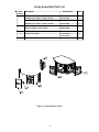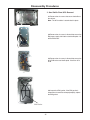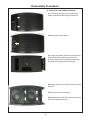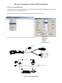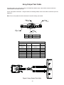
1
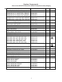
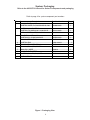
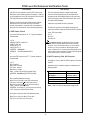
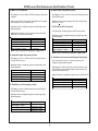
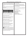
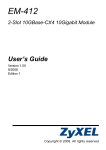
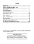
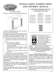
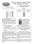
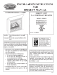
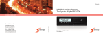
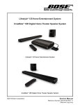
Contents
Safety Information ............................................................................................................................. 2
Electrostatic Discharge Sensitive (ESDS) Device Handling ....................................................... 2
Product Description ......................................................................................................................... 3
Specifications .................................................................................................................................... 3
Part List Notes .................................................................................................................................. 3
Figure 1. Packaging View .................................................................................................................... 5
Main Assembly Part List ................................................................................................................... 6
Figure 2. Main Assembly Part List ....................................................................................................... 7
DSP PCB Part List ...................................................................................................................... 8-17
Power Supply PCB Part List .................................................................................................... 18-22
Array Assembly Part List ................................................................................................................. 23
Figure 3. Array Exploded View ........................................................................................................... 23
Disassembly Procedures ......................................................................................................... 24-26
Set up a Computer to Issue Tap Commands ............................................................................... 27
Figure 4. TAP Cable 299656 ............................................................................................................. 27
Issuing TAP Commands to the Bass Module ............................................................................... 28
Array Output Test Cable ................................................................................................................. 29
Figure 5. Array Output Test Cable ..................................................................................................... 29
System Level Test .......................................................................................................................... 30
PCB Level Performance Verification Tests ........................................................................... 31-33
Revision History ............................................................................................................................. 34
CAUTION: THE BOSE® LIFESTYLE® 235 MODULE CONTAINS
NO USER SERVICEABLE PARTS. TO PREVENT WARRANTY
INFRACTIONS, REFER SERVICING TO WARRANTY SERVICE
STATIONS OR FACTORY SERVICE.
PROPRIETARY INFORMATION
THIS DOCUMENT CONTAINS PROPRIETARY INFORMATION OF
BOSE CORPORATION WHICH IS BEING FURNISHED ONLY FOR
THE PURPOSE OF SERVICING THE IDENTIFIED BOSE PRODUCT
BY AN AUTHORIZED SERVICE CENTER OR OWNER OF THE BOSE
PRODUCT, AND SHALL NOT BE REPRODUCED OR USED FOR ANY
OTHER PURPOSE.
1
SAFETY INFORMATION
1. Parts that have special safety characteristics are identified by the
symbol on schematics or by
special notes on the parts list. Use only replacement parts that have critical characteristics recommended by the manufacturer.
2. Make leakage current or resistance measurements to determine that exposed parts are acceptably
insulated from the supply circuit before returning the unit to the customer.
Use the following checks to perform these measurements:
A. Leakage Current Hot Check-With the unit completely reassembled, plug the AC line cord directly
into a 120V AC outlet. (Do not use an isolation transformer during this test.) Use a leakage current
tester or a metering system that complies with American National Standards Institute (ANSI) C101.1
“Leakage Current for Appliances” and Underwriters Laboratories (UL) 6500/60065 / IEC 60065 paragraph 9.1.1. With the unit AC switch first in the ON position and then in OFF position, measure from a
known earth ground (metal waterpipe, conduit, etc.) to all exposed metal parts of the unit (antennas,
handle bracket, metal cabinet, screwheads, metallic overlays, control shafts, etc.), especially any
exposed metal parts that offer an electrical return path to the chassis. Any current measured must not
exceed 0.5 milliamp. Reverse the unit power cord plug in the outlet and repeat test. ANY MEASUREMENTS NOT WITHIN THE LIMITS SPECIFIED HEREIN INDICATE A POTENTIAL SHOCK HAZARD
THAT MUST BE ELIMINATED BEFORE RETURNING THE UNIT TO THE CUSTOMER.
B. Insulation Resistance Test Cold Check-(1) Unplug the power supply and connect a jumper wire
between the two prongs of the plug. (2) Turn on the power switch of the unit. (3) Measure the resistance with an ohmmeter between the jumpered AC plug and each exposed metallic cabinet part on
the unit. When testing 3 wire products, the resistance measured to the product enclosure should be
between 2 and infinite MOhms. Also, the resistance measured to exposed input/output connectors
should be between 4 and infinite MOhms. When testing 2 wire products, the resistance measured to
exposed input/output connectors should be between 4 and infinite MOhms. If it is not within the limits
specified, there is the possibility of a shock hazard, and the unit must be repaired and rechecked
before it is returned to the customer.
ELECTROSTATIC DISCHARGE SENSITIVE (ESDS) DEVICE HANDLING
This unit contains ESDS devices. We recommend the following precautions when repairing,
replacing or transporting ESDS devices:
• Perform work at an electrically grounded work station.
• Wear wrist straps that connect to the station or heel straps that connect to conductive floor mats.
• Avoid touching the leads or contacts of ESDS devices or PC boards even if properly grounded.
Handle boards by the edges only.
• Transport or store ESDS devices in ESD protective bags, bins, or totes. Do not insert unprotected
devices into materials such as plastic, polystyrene foam, clear plastic bags, bubble wrap or plastic
trays.
2
Product Description
The Lifestyle® 235 Home Entertainment System consists of a control console (AV35), an
Acoustimass® module, two Gemstone® ES speaker arrays, and a remote control (RC23).
System Features:
• Unify intelligent integration system to help you easily add devices to your system
• ADAPTiQ audio calibration system that optimizes system performance for your room
• RF remote control
• HDMI® connectivity
• Video up-conversion to 1080p
• Photo viewing using a USB flash drive
• Interface and dock compatible with iPod/iPhone devices
• AM/FM radio
• Can deliver sound in up to 14 additional rooms or locations
Note: Refer to the AV35 console service manual 317084-SM for to service the console.
Specifications
Remote control
Frequency: 2.4 GHz
Range: 33 ft (10 m)
Control console power supply rating
AC input: 100-240V 50/60 Hz, 0.5A
DC output: 12V 20W Max.
Acoustimass® module rating
USA/Canada: 100-120V 50/60 Hz 350W
International: 220-240V 50/60 Hz 350W
Dual voltage: 100-120/220-240V 50/60 Hz 350W
Part List Notes
1. This part is not normally available from customer service. Approval from the Field Service Manager
is required before ordering.
2. The individual parts located on the PCB are listed in the part list.
3.
This part is critical for safety purposes. Failure to use a substitute replacement with the
same safety characteristics as the recommended replacement part might create shock, fire and/or
other hazards.
3
System Components
Refer to the AV35 STCH manual for Series III components and packaging
Description
Part Number
Qty
Note
REMOTE, RF, RC35T-L, USA/EU
314596-009
1
CONSOLE ASSY, AV-25/35, US, SERVICE
CONSOLE ASSY, AV-25/35, EURO, SERVICE
CONSOLE ASSY, AV-25/35, JAPAN, SERVICE
CONSOLE ASSY, AV-25/35, APAC, SERVICE
BASSBOX ASSY, LS235, DUAL, BLK, SERVICE
BASSBOX ASSY, LS235, 230V, BLK, SERVICE
BASSBOX ASSY, LS235, 230V, WHT, SERVICE
ARRAY ASSY, RIGHT, BLACK
ARRAY ASSY, RIGHT, WHITE
ARRAY ASSY, LEFT, BLACK
ARRAY ASSY, LEFT, WHITE
DOCK, IPOD, LIFESTYLE
330769-151S
330769-254S 330769-351S
330769-551S
326084-610S
326084-213S 326084-223S
330391-0010
330391-0020
330391-0110
330391-0120
318585-1011
1
1
DRIVE, FLASH, USB W/O SILICONE CASE
353201-0010
1
CABLE, DIN-9/DIN-9
302580-1001
1
CABLE, ARRAY, 9PIN, BLACK
CABLE, ARRAY, 9PIN, WHITE
CABLE, HDMI
331294-1010
331294-0020
326853-0110
1
CABLE, RCA, 6 FT
185931-101
1
LINE CORD , 120V, US
LINE CORD, 220V, EUR, DET, BLK, 1500
LINE CORD, 230V, UKS, DET, BLK, 1500
LINE CORD, 100V, JPN, DET, BLK, 1500
LINE CORD, 230V, KOREA, BLK, 1500
LINE CORD, 240V, AUS, DET, BLK, 1500 PWR PACK, FLR, UNVSL, 12V, 20W, BLK
258491-101
280135-1310
280138-1310
280136-1310
311668-1310
284243-1310 316263-103
2
3
1
3
3 EMITTER IR DONGLE
324714-1010
1
ANTENNA, FM DIPOLE, F CONN
ANTENNA, FM DIPOLE, PAL CONN
ANTENNA ASSY, AM, CD20
347426-0010
347423-0010
199824-002
1
FOOT, CLEAR, .312x.085, 4'
178321-0
2
BUMPER, RECESSED, FOOT, .88"
142839
4
KIT, ADAPTIQ HEADSET
307702-001
1
GUIDE, SETUP, AIM
GUIDE, SETUP, EUROPE
GUIDE, SETUP, APAC
GUIDE, SETUP, BKK GUIDE, OPERATING, AIM
GUIDE, OPERATING, EUROPE
GUIDE, OPERATING, APAC
GUIDE, OPERATING, BKK REMOTE BATTERY DOOR
328338-0010
328339-0010
328340-0010
328779-0010 343989-0010
343990-0010
343991-0010
343992-0010 322542-001S
1
®
4
1
1
1
1
1
1
System Packaging
Refer to the AV35 STCH manual for Series III components and packaging
Refer to page 4 for system component part numbers
Item
Description
Part Number
Qty
1
CONSOLE KIT, LS 235
CARTON, CORR, D-C,20.25X16X5.88, 200
320600-0010
1
1
2
SAT PACK, GS ES ARRAY
CARTON,, DC,200B, 9.88 X 16.00 X 4.25
328131-0010
1
1
ARRAY CARTON,125E,6X2.63X4.38
328129-0010
2
ESSENTIALS KIT, LS 235
-
1
CARTON,D-C,12.88X16.00X4.25
320599-0010
1
PACKING,TRAY, PULP
321500-0010
1
4
5
CARTON, RSC
PACKING,FOAM,EPS,BBOX
348414-0010
293513-001
1
1
6
7
PACKING,FOAM,EPS,BB-BTM
BAG,POLY,HDPE
295444-001
196638
1
1
8
COMMITMENT LETTER
251001
1
60
CARTON, HSC-FOL,D-C,CORR
325008-0010
1
61
LINE CORD KIT
-
1
3
Figure 1. Packaging View
5
Main Assembly Part List
Item
1
Description
Part Number
Qty
2
PCB ASSY, LS235, POWER SUPPLY , DUAL V
PCB ASSY, LS235, POWER SUPPLY, 230V EUP
PCB DSP SLAB, LS235, SERVICE
301749-003
328923-001S
329003-031S
1
1 3
LABEL, I/O, D-SUB CONN
327478-0010
1 4
CABLE, FFC, 10 POS
289482-10
1 5
GASKET, I/O CONNECTORS, D-SUB
327479-0010
1 6
SHIELD, EMI, POWER PCB
286776-001
1 7
HEATSINK, POWER AMP
286779-001
1 8
9
CLIP, SPRING
HEATSINK, TWID AMP
142864
289739-002
1 1 10
PAD, SIL, TWID AMPS
289734-001
1 Note
3
3
11
PAD, SIL, BASS AMP
289735-001
1 12
312274-021
312274-022
286955-001
1 13
COVER, AMP, D-SUB, BLACK
COVER, AMP, D-SUB, WHITE
BRACKET, AMP COVER SECURE
14
SPACER, POWER AMP, WEB
313593-001
1 15
SCREW, TAPP, 8-11x.75, PAN, XRC/SQ
289388-012
18 16
SCREW, TT, 8-32X0.5, PAN, XREC/SQ (BLACK)
SCREW, 8-32X.5, RLX, PN, QDRX, ZNC (WHITE)
SCREW, TAPP, 8-11x.437, PAN, XRC/S
289393-008
292354-08
289388-007
10 320005-0010
3 19
SCREW, TORX, , 5-15X..625, ROUND HD,
POLYFAST
SCREW, TAPP, M3.5x16, PAN, TRX
288593-010
3 20
SCREW, 8-32X.87, RLX, PN, QDRX, ZNC
292354-14
7 21
GASKETING, EMI
256826-003
1 22
GASKET, EMI, ELASTOMER, Ni/C
294531-001
1 23
SCREW, TT, 8-32X2.00, PAN, XREC/SQ
289393-032
2 24
BAFFLE, STEEL, PLATE
293243-001
1 25
286744-101
286744-102
289873-101
2 -
LOGO, BOSE, BLACK
LOGO, BOSE, WHITE
CABLE, DC POWER
1 3
-
CABLE, AC POWER
289872-101
1 3
17
18
Note: The woofers are not accessible
Item numbers reference call outs in Figure 2 on next page
6
2 6 Item number call outs are referenced in the main
assembly part list on the previous page
16
12
The woofers are not accessible
25
9
7
15
23
3X
11
10
5
14
13
3x
8
20
2
4
15
21
22
6
17
25
1
16
Figure 2. Main Assembly Part List
7
24
3
19
3x
18
DSP PCB Part List
Resistors
Reference
Designator
R3
R4
R7
R8
R9
R10
R11
R20
R21
R38
R40
R42
R43
R47
R51
R69
R70
R71
R72
R73
R74
R75
R76
R77
R78
R79
R81
R82
R83
R84
R90
R101
R102
R111
R112
R114
R115
R710
R711
R712
R713
R714
R717
R718
R719
R720
R721
R722
R723
R724
R738
R739
Description
Part Number
7.87K, 0603, .1W, 1%
15K, 0603, .1W, 1%
4.75K, 0603, .1W, 1%
4.75K, 0603, .1W, 1%
7.15K, 0603, .1W, 1%
10K, 0603, .1W, 1%
10K, 0603, .1W, 1%
47.5K, 0603, .1W, 1%
470 OHMS, 0603, .1W, 5%
1.82K, 0603, 1/10W, 1%
1.82K, 0603, 1/10W, 1%
7.5K, 0603, .1W, 1%
7.5K, 0603, .1W, 1%
274 OHM, 0603, .1W, 1%
274 OHM, 0603, .1W, 1%
1.82K, 0603, 1/10W, 1%
1.82K, 0603, 1/10W, 1%
1.82K, 0603, 1/10W, 1%
7.5K, 0603, .1W, 1%
7.5K, 0603, .1W, 1%
7.5K, 0603, .1W, 1%
274 OHM, 0603, .1W, 1%
274 OHM, 0603, .1W, 1%
274 OHM, 0603, .1W, 1%
330 OHMS, 0603, .1W, 5%
330 OHMS, 0603, .1W, 5%
100 OHM, 0603, .1W, 5%
100 OHM, 0603, .1W, 5%
100 OHM, 0603, .1W, 5%
100 OHM, 0603, .1W, 5%
20 OHM, 0805, 1/10W, 5%
47.5K, 0603, .1W, 1%
47.5K, 0603, .1W, 1%
17.4K, 0603, .1W, 1%
10K, 0603, .1W, 1%
4.70 OHM, 0603, 100MW, 1%, SMD
ARRAY, SMT, 4 POS, 5%, 10K
4.75K, 0603, .1W, 1%
4.75K, 0603, .1W, 1%
4.75K, 0603, .1W, 1%
4.75K, 0603, .1W, 1%
100 OHM, 0603, .1W, 5%
47.5K, 0603, .1W, 1%
100K, 0603, .1W, 1%
332K, 0603, .1W, 1%
2K, 0603, .1W, 1%
365 OHM, 0603, .1W, 1%
11K, 0603, .1W, 1%
7.87K, 0603, .1W, 1%
2.0 OHM, 0603, SMD, 100mW
10K, 0603, .1W, 1%
10K, 0603, .1W, 1%
8
191465-7871
191465-1502
191465-4751
191465-4751
191465-7151
191465-1002
191465-1002
191465-4752
199403-471
191465-1821
191465-1821
191465-7501
191465-7501
191465-2740
191465-2740
191465-1821
191465-1821
191465-1821
191465-7501
191465-7501
191465-7501
191465-2740
191465-2740
191465-2740
199403-331
199403-331
199403-101
199403-101
199403-101
199403-101
133626-2005
191465-4752
191465-4752
191465-1742
191465-1002
191465-4R70
186433-1034
191465-4751
191465-4751
191465-4751
191465-4751
199403-101
191465-4752
191465-1003
191465-3323
191465-2001
191465-3650
191465-1102
191465-7871
199403-2R0
191465-1002
191465-1002
Note
DSP PCB Part List
Resistors
Reference
Designator
R746
R747
R748
R800
R801
R802
R803
R805
R806
R807
R809
R810
R811
R812
R818
R819
R820
R821
R823
R825
R828
R829
R830
R832
R833
R834
R835
R836
R837
R838
R900
R901
R902
R903
R904
R905
R907
R909
R910
R911
R912
R913
R914
R915
R917
R919
R920
R921
R922
R923
R924
R925
Description
Part Number
1.02K, 0603, .1W, 1%
1.02K, 0603, .1W, 1%
1.62K, 0603, .1W, 1%
1.02K, 0603, .1W, 1%
9.09K, 0603, .1W, 1%
9.09K, 0603, .1W, 1%
9.09K, 0603, .1W, 1%
1.02K, 0603, .1W, 1%
1.02K, 0603, .1W, 1%
1.02K, 0603, .1W, 1%
560 OHM, 0603, .1W, 1%
560 OHM, 0603, .1W, 1%
300 OHMS, 0603, .1W, 5%
9.09K, 0603, .1W, 1%
9.09K, 0603, .1W, 1%
9.09K, 0603, .1W, 1%
2.0 OHM, 0603, SMD, 100mW
2.0 OHM, 0603, SMD, 100mW
2.0 OHM, 0603, SMD, 100mW
4.70 OHM, 0603, 100MW, 1%, SMD
4.70 OHM, 0603, 100MW, 1%, SMD
100K, 0603, .1W, 1%
100K, 0603, .1W, 1%
100K, 0603, .1W, 1%
100K, 0603, .1W, 1%
100K, 0603, .1W, 1%
100K, 0603, .1W, 1%
47.5K, 0603, .1W, 1%
47.5K, 0603, .1W, 1%
5.1K, 0603, .1W, 5%
9.09K, 0603, .1W, 1%
9.09K, 0603, .1W, 1%
1.02K, 0603, .1W, 1%
1.02K, 0603, .1W, 1%
560 OHM, 0603, .1W, 1%
560 OHM, 0603, .1W, 1%
9.09K, 0603, .1W, 1%
9.09K, 0603, .1W, 1%
2.0 OHM, 0603, SMD, 100mW
2.0 OHM, 0603, SMD, 100mW
56K, 0603, .1W, 5%
4.70 OHM, 0603, 100MW, 1%, SMD
4.70 OHM, 0603, 100MW, 1%, SMD
15K, 0603, .1W, 1%
56K, 0603, .1W, 5%
15K, 0603, .1W, 1%
75K, 0603, .1W, 5%
5.1K, 0603, .1W, 5%
56K, 0603, .1W, 5%
15K, 0603, .1W, 1%
56K, 0603, .1W, 5%
15K, 0603, .1W, 1%
9
191465-1021
191465-1021
191465-1621
191465-1021
191465-9091
191465-9091
191465-9091
191465-1021
191465-1021
191465-1021
191465-5600
191465-5600
199403-301
191465-9091
191465-9091
191465-9091
199403-2R0
199403-2R0
199403-2R0
191465-4R70
191465-4R70
191465-1003
191465-1003
191465-1003
191465-1003
191465-1003
191465-1003
191465-4752
191465-4752
199403-512
191465-9091
191465-9091
191465-1021
191465-1021
191465-5600
191465-5600
191465-9091
191465-9091
199403-2R0
199403-2R0
199403-563
191465-4R70
191465-4R70
191465-1502
199403-563
191465-1502
199403-753
199403-512
199403-563
191465-1502
199403-563
191465-1502
Note
DSP PCB Part List
Resistors
Reference
Designator
R926
R927
R7128
R7129
R7130
R7131
R7134
R7135
R7136
R7137
R7138
R7139
R7140
R7141
R7142
R7143
R7144
R7145
R7146
R7147
R7149
R7150
R7151
R7152
R7153
R7154
R7155
R9213
R9214
R9215
R9216
R9226
R9227
R9228
R9229
R9230
R9231
R9232
R9233
R9234
R9235
R9236
R9237
R9238
R9239
R9242
R9243
R9245
R9251
R9259
R9260
R9261
Description
Part Number
75K, 0603, .1W, 5%
5.1K, 0603, .1W, 5%
10K, 0603, .1W, 1%
10K, 0603, .1W, 1%
100K, 0603, .1W, 1%
18.2K, 0603, .1W, 1%
1.02K, 0603, .1W, 1%
4.75K, 0603, .1W, 1%
4.75K, 0603, .1W, 1%
4.75K, 0603, .1W, 1%
4.75K, 0603, .1W, 1%
4.75K, 0603, .1W, 1%
4.75K, 0603, .1W, 1%
4.75K, 0603, .1W, 1%
4.75K, 0603, .1W, 1%
4.75K, 0603, .1W, 1%
4.75K, 0603, .1W, 1%
4.75K, 0603, .1W, 1%
4.75K, 0603, .1W, 1%
4.75K, 0603, .1W, 1%
750 OHM, 0603, .1W, 1%
750 OHM, 0603, .1W, 1%
750 OHM, 0603, .1W, 1%
9.09K, 0603, .1W, 1%
JUMPER, CHIP, 0603
100K, 0603, .1W, 1%
4.75K, 0603, .1W, 1%
2.32K, 0603, .1W, 1%
2.32K, 0603, .1W, 1%
750 OHM, 0603, .1W, 1%
750 OHM, 0603, .1W, 1%
1 OHM, 0805, 1/10W, 5%
1 OHM, 0805, 1/10W, 5%
1 OHM, 0805, 1/10W, 5%
1 OHM, 0805, 1/10W, 5%
5.1K, 0603, .1W, 5%
5.1K, 0603, .1W, 5%
100K, 0603, .1W, 1%
1.62K, 0603, .1W, 1%
150 OHMS, 0603, .1W, 1%
10K, 0603, .1W, 1%
7.15K, 0603, .1W, 1%
49.9K, 0603, .1W, 1%
2.32K, 0603, .1W, 1%
9.09K, 0603, .1W, 1%
10 OHM, 0603, .1W, 5%
10 OHM, 0603, .1W, 5%
1.62K, 0603, .1W, 1%
1.00K, 0805, 1/10W, 5%
JUMPER, CHIP, 0603
JUMPER, CHIP, 0603
JUMPER, CHIP, 0603
199403-753
199403-512
191465-1002
191465-1002
191465-1003
191465-1822
191465-1021
191465-4751
191465-4751
191465-4751
191465-4751
191465-4751
191465-4751
191465-4751
191465-4751
191465-4751
191465-4751
191465-4751
191465-4751
191465-4751
191465-7500
191465-7500
191465-7500
191465-9091
196042
191465-1003
191465-4751
191465-2321
191465-2321
191465-7500
191465-7500
133626-1R05
133626-1R05
133626-1R05
133626-1R05
199403-512
199403-512
191465-1003
191465-1621
191465-1500
191465-1002
191465-7151
191465-4992
191465-2321
191465-9091
199403-100
199403-100
191465-1621
133626-1025
196042
196042
196042
10
Note
DSP PCB Part List
Resistors
Reference
Designator
R9286
R9287
R9288
R9292
R9293
R9297
R9298
R9299
R9300
R9301
R9302
R9303
R9304
Description
Part Number
10K, 0603, .1W, 1%
1.02K, 0603, .1W, 1%
7.32K, 0603, .1W, 1%
1.02K, 0603, .1W, 1%
2.32K, 0603, .1W, 1%
33.2K, 0603, .1W, 1%
100 OHM, 0603, .1W, 5%
1.02K, 0603, .1W, 1%
7.87K, 0603, .1W, 1%
1.02K, 0603, .1W, 1%
10K, 0603, .1W, 1%
8.45K, 0603, .1W, 1%
1.02K, 0603, .1W, 1%
Note
191465-1002
191465-1021
191465-7321
191465-1021
191465-2321
191465-3322
199403-101
191465-1021
191465-7871
191465-1021
191465-1002
191465-8451
191465-1021
Capacitors
Reference
Designator
C1
C2
C3
C4
C5
C6
C8
C9
C10
C11
C12
C13
C17
C18
C20
C22
C25
C26
C28
C30
C44
C45
C46
C47
C48
C51
C52
C53
C57
C58
C92
C125
C126
Description
Part Number
.033uF, 0603, X7R, 50V, 10%
33000pF, X7R SMD, 0603, 25V
33000pF, X7R SMD, 0603, 25V
33000pF, X7R SMD, 0603, 25V
33000pF, X7R SMD, 0603, 25V
33000pF, X7R SMD, 0603, 25V
33000pF, X7R SMD, 0603, 25V
33000pF, X7R SMD, 0603, 25V
180pF, 0603, COG, 50V
33000pF, X7R SMD, 0603, 25V
33000pF, X7R SMD, 0603, 25V
10uF, EL, 85, 16V, 20%
.01uF, 0603, X7R, 50V
.01uF, 0603, X7R, 50V
22pF, 0603, COG, 50V, 5%
22pF, 0603, COG, 50V, 5%
680 pF, 0603, COG, SMD, 25V, 5%
680 pF, 0603, COG, SMD, 25V, 5%
1.0nF , 0603, COG, SMD, 25V, 5%
1.0nF , 0603, COG, SMD, 25V, 5%
680 pF, 0603, COG, SMD, 25V, 5%
680 pF, 0603, COG, SMD, 25V, 5%
680 pF, 0603, COG, SMD, 25V, 5%
1.0nF , 0603, COG, SMD, 25V, 5%
1.0nF , 0603, COG, SMD, 25V, 5%
33000pF, X7R SMD, 0603, 25V
33000pF, X7R SMD, 0603, 25V
1.0nF , 0603, COG, SMD, 25V, 5%
4700pF, 0603, X7R, 50V
4700pF, 0603, X7R, 50V
4.7pF, 0603, COG, 50V
33000pF, X7R SMD, 0603, 25V
33000pF, X7R SMD, 0603, 25V
11
191470-333
257154-333K25
257154-333K25
257154-333K25
257154-333K25
257154-333K25
257154-333K25
257154-333K25
188454-181
257154-333K25
257154-333K25
177902-100C
191470-103
191470-103
188454-220
188454-220
268368-681
268368-681
268368-102
268368-102
268368-681
268368-681
268368-681
268368-102
268368-102
257154-333K25
257154-333K25
268368-102
191470-472
191470-472
188454-4R7
257154-333K25
257154-333K25
Note
DSP PCB Part List
Capacitors
Reference
Designator
C127
C128
C129
C130
C132
C135
C137
C138
C139
C140
C141
C142
C143
C144
C145
C146
C147
C150
C151
Description
Part Number
33000pF, X7R SMD, 0603, 25V
33000pF, X7R SMD, 0603, 25V
33000pF, X7R SMD, 0603, 25V
10uF, EL, 85, 16V, 20%
10uF, EL, 85, 16V, 20%
22uF, EL, 85, 20%, 16V
10uF EL, 85, 20%, 35V
10uF, EL, 85, 16V, 20%
33000pF, X7R SMD, 0603, 25V
33000pF, X7R SMD, 0603, 25V
33000pF, X7R SMD, 0603, 25V
100pF, 0603, COG, 50V, 5%
0.1uF, x7r, 0603, 10%, 50V
2200pF, 0603, X7R, 50V
33000pF, X7R SMD, 0603, 25V
470pF, 0603, COG, 50V, 5%
.01uF, 0603, X7R, 50V
0.1uF, x7r, 0603, 10%, 50V
0.01uF , 0805, X7R, 50V, 10%
257154-333K25
257154-333K25
257154-333K25
177902-100C
177902-100C
177902-220C
177902-100V
177902-100C
257154-333K25
257154-333K25
257154-333K25
188454-101
191470-104
191470-222
257154-333K25
188454-471
191470-103
191470-104
286499-103
C153
C154
C155
C162
C163
C164
C165
C166
C201
C202
C700
C701
C704
C705
C706
C707
C708
C709
C710
C711
C712
C713
C714
C715
C716
C717
C718
C719
C720
C722
C723
C724
C725
100uF , 7343, tant, 10%, lo-R, 10V
.047uF, 0603, X7R, 50V
1uF, EL, 85, 50V, 20%
EL, SMD, 105, 35V, 20%, 47uF
180pF, 0603, COG, 50V
180pF, 0603, COG, 50V
180pF, 0603, COG, 50V
180pF, 0603, COG, 50V
180pF, 0603, COG, 50V
180pF, 0603, COG, 50V
22pF , COG, 0402, 50V, 5%
22pF , COG, 0402, 50V, 5%
22pF , COG, 0402, 50V, 5%
22pF , COG, 0402, 50V, 5%
22pF , COG, 0402, 50V, 5%
22pF , COG, 0402, 50V, 5%
22pF , COG, 0402, 50V, 5%
22pF , COG, 0402, 50V, 5%
22pF , COG, 0402, 50V, 5%
22pF , COG, 0402, 50V, 5%
22pF , COG, 0402, 50V, 5%
22pF , COG, 0402, 50V, 5%
22pF , COG, 0402, 50V, 5%
22pF , COG, 0402, 50V, 5%
22pF , COG, 0402, 50V, 5%
22pF , COG, 0402, 50V, 5%
22pF , COG, 0402, 50V, 5%
22pF , COG, 0402, 50V, 5%
22pF , COG, 0402, 50V, 5%
22pF , COG, 0402, 50V, 5%
22pF , COG, 0402, 50V, 5%
22pF , COG, 0402, 50V, 5%
22pF , COG, 0402, 50V, 5%
275411-107
191470-473
177902-010H
306169-470VF
188454-181
188454-181
188454-181
188454-181
188454-181
188454-181
268364-220
268364-220
268364-220
268364-220
268364-220
268364-220
268364-220
268364-220
268364-220
268364-220
268364-220
268364-220
268364-220
268364-220
268364-220
268364-220
268364-220
268364-220
268364-220
268364-220
268364-220
268364-220
268364-220
12
Note
3
DSP PCB Part List
Capacitors
Reference
Designator
C726
C727
C728
C729
C730
C731
C732
C733
C734
C802
C804
C805
C808
C810
C811
C812
C814
C815
C816
C817
Description
Part Number
22pF , COG, 0402, 50V, 5%
22pF , COG, 0402, 50V, 5%
22pF , COG, 0402, 50V, 5%
22pF , COG, 0402, 50V, 5%
22pF , COG, 0402, 50V, 5%
22pF , COG, 0402, 50V, 5%
22pF , COG, 0402, 50V, 5%
22pF , COG, 0402, 50V, 5%
22pF , COG, 0402, 50V, 5%
10uF, EL, 85, 16V, 20%
1uF, EL, 85, 50V, 20%
1uF, EL, 85, 50V, 20%
22uF, EL, 85, 20%, 16V
.01uF, 0603, X7R, 50V
.01uF, 0603, X7R, 50V
.047uF, 0603, X7R, 5%, 25V
.0068uF, 0603, X7R, 50V
.0068uF, 0603, X7R, 50V
.047uF, 0603, X7R, 5%, 25V
0.1uF , 0805, X7R, 50V, 10%
268364-220
268364-220
268364-220
268364-220
268364-220
268364-220
268364-220
268364-220
268364-220
177902-100C
177902-010H
177902-010H
177902-220C
191470-103
191470-103
196999-473
191470-682
191470-682
196999-473
286499-104
3
C819
0.1uF , 0805, X7R, 50V, 10%
286499-104
3
C820
0.1uF , 0805, X7R, 50V, 10%
286499-104
3
C821
0.1uF , 0805, X7R, 50V, 10%
286499-104
3
C822
0.1uF , 0805, X7R, 50V, 10%
286499-104
3
C827
0.1uF , 0805, X7R, 50V, 10%
286499-104
3
C828
0.1uF , 0805, X7R, 50V, 10%
286499-104
3
C829
0.1uF , 0805, X7R, 50V, 10%
286499-104
3
C830
0.1uF , 0805, X7R, 50V, 10%
286499-104
3
C832
0.1uF , 0805, X7R, 50V, 10%
286499-104
3
C833
C835
C836
1000pF, 0603, X7R, 50V
1000pF, 0603, X7R, 50V
0.01uF , 0805, X7R, 50V, 10%
191470-102
191470-102
286499-103
3
C839
0.01uF , 0805, X7R, 50V, 10%
286499-103
3
C841
C842
C844
C845
C850
C852
C853
4.7pF, 0603, COG, 50V
4.7pF, 0603, COG, 50V
4.7pF, 0603, COG, 50V
4.7pF, 0603, COG, 50V
4.7pF, 0603, COG, 50V
4.7pF, 0603, COG, 50V
4.7pF, 0603, COG, 50V
188454-4R7
188454-4R7
188454-4R7
188454-4R7
188454-4R7
188454-4R7
188454-4R7
13
Note
DSP PCB Part List
Capacitors
Reference
Designator
C855
C856
C858
C859
C860
C861
C862
C863
C864
C865
C866
C867
C868
C869
C901
C902
C904
C905
C906
C907
C908
Description
Part Number
4.7pF, 0603, COG, 50V
4.7pF, 0603, COG, 50V
4.7pF, 0603, COG, 50V
4.7pF, 0603, COG, 50V
4.7pF, 0603, COG, 50V
4.7pF, 0603, COG, 50V
4.7pF, 0603, COG, 50V
4.7pF, 0603, COG, 50V
4.7pF, 0603, COG, 50V
4.7pF, 0603, COG, 50V
4.7pF, 0603, COG, 50V
4.7pF, 0603, COG, 50V
4.7pF, 0603, COG, 50V
4.7pF, 0603, COG, 50V
1uF, EL, 85, 50V, 20%
1uF, EL, 85, 50V, 20%
.01uF, 0603, X7R, 50V
.01uF, 0603, X7R, 50V
.0068uF, 0603, X7R, 50V
.0068uF, 0603, X7R, 50V
0.1uF , 0805, X7R, 50V, 10%
188454-4R7
188454-4R7
188454-4R7
188454-4R7
188454-4R7
188454-4R7
188454-4R7
188454-4R7
188454-4R7
188454-4R7
188454-4R7
188454-4R7
188454-4R7
188454-4R7
177902-010H
177902-010H
191470-103
191470-103
191470-682
191470-682
286499-104
3
C911
0.1uF , 0805, X7R, 50V, 10%
286499-104
3
C912
0.1uF , 0805, X7R, 50V, 10%
286499-104
3
C913
0.1uF , 0805, X7R, 50V, 10%
286499-104
3
C914
0.1uF , 0805, X7R, 50V, 10%
286499-104
3
C915
0.1uF , 0805, X7R, 50V, 10%
286499-104
3
C916
C917
C918
1000pF, 0603, X7R, 50V
1000pF, 0603, X7R, 50V
0.01uF , 0805, X7R, 50V, 10%
191470-102
191470-102
286499-103
3
C919
0.01uF , 0805, X7R, 50V, 10%
286499-103
3
C920
C921
C922
C923
C950
C952
C953
C954
C955
C956
C957
C958
C959
0.1uF, x7r, 0603, 10%, 50V
0.1uF, x7r, 0603, 10%, 50V
1000pF, 0603, X7R, 50V
180pF, 0603, COG, 50V
4.7pF, 0603, COG, 50V
4.7pF, 0603, COG, 50V
4.7pF, 0603, COG, 50V
4.7pF, 0603, COG, 50V
4.7pF, 0603, COG, 50V
4.7pF, 0603, COG, 50V
4.7pF, 0603, COG, 50V
4.7pF, 0603, COG, 50V
4.7pF, 0603, COG, 50V
191470-104
191470-104
191470-102
188454-181
188454-4R7
188454-4R7
188454-4R7
188454-4R7
188454-4R7
188454-4R7
188454-4R7
188454-4R7
188454-4R7
14
Note
DSP PCB Part List
Capacitors
Reference
Designator
C960
C9203
C9204
C9205
C9206
C9209
C9210
C9211
C9212
C9213
C9216
C9223
C9224
C9225
C9226
C9227
C9236
C9237
C9238
C9239
C9240
C9241
Description
Part Number
4.7pF, 0603, COG, 50V
10uF EL, 85, 20%, 35V
33000pF, X7R SMD, 0603, 25V
EL., SMD, 105, 50V, 20%, 22uF
EL., SMD, 105, 50V, 20%, 22uF
33000pF, X7R SMD, 0603, 25V
470pF, 0603, COG, 50V, 5%
.022uF, 0603, X7R, 25V
.0068uF, 0603, X7R, 50V
7343, tant, 10%, lo-R, 47u/16V
180pF, 0805, COG, 50V, 5%
180pF, 0603, COG, 50V
180pF, 0603, COG, 50V
180pF, 0603, COG, 50V
180pF, 0603, COG, 50V
180pF, 0603, COG, 50V
0.1uF , 0805, X7R, 50V, 10%
.01uF, 0603, X7R, 50V
180pF, 0603, COG, 50V
180pF, 0603, COG, 50V
1.0uF, 1206, X7R, 16V
0.01uF , 0805, X7R, 50V, 10%
188454-4R7
177902-100V
257154-333K25
306245-220FD
306245-220FD
257154-333K25
188454-471
196999-223
191470-682
275411-476
133622-181
188454-181
188454-181
188454-181
188454-181
188454-181
286499-104
191470-103
188454-181
188454-181
181998-105
286499-103
C9242
C9243
C9245
C9246
C9247
C9248
C9249
C9251
C9252
C9253
C9254
C9260
1210, X7R, 50V, 1.0uF, 10%
180pF, 0603, COG, 50V
33000pF, X7R SMD, 0603, 25V
.047uF, 0603, X7R, 50V
33000pF, X7R SMD, 0603, 25V
33000pF, X7R SMD, 0603, 25V
33000pF, X7R SMD, 0603, 25V
1000pF, 0603, X7R, 50V
1000pF, 0603, X7R, 50V
1000pF, 0603, X7R, 50V
1000pF, 0603, X7R, 50V
10uF, EL, 85, 16V, 20%
294151-105
188454-181
257154-333K25
191470-473
257154-333K25
257154-333K25
257154-333K25
191470-102
191470-102
191470-102
191470-102
177902-100C
Note
3
Diodes
Reference
Designator
D1
D2
D901
D903
D904
DS1
DS2
ZR1
Description
Part Number
DIODE, SCHOTTKY, 70V, 2nS, BAS70,
SOT-23
DIODE, ZEN, SOD-123, 6V, .5W, 5%
SWTCHING, SCHOTTKY, 1A/40V
RECTIFYING, MINI-DIODE
RECTIFYING, MINI-DIODE
LED, SMD, GREEN
LED, SMD, YELLOW
DIODE, SOT-23, BAV 99
15
329354-0010
174265-5233
195637-3
188455-001
188455-001
256781-002
256781-003
147239
Note
DSP PCB Part List
Transistors
Reference
Designator
Q7005
Q7006
Q7007
Q800
Q801
Q802
Q900
Q902
Q903
Q904
Q9028
Q9031
Q9034
Q9035
Q9036
Description
Part Number
BPLR, N, 40V, 200mA, SOT23
BPLR, P, 40V, 200mA, SOT23
BPLR, P, 40V, 200mA, SOT23
BPLR, N, 55V, 150mA, SOT23
P, 50V, 150MA, SOT
BPLR, N, 40V, 200mA, SOT23
BPLR, N, 55V, 150mA, SOT23
P, 50V, 150MA, SOT
BPLR, N, 55V, 150mA, SOT23
P, 50V, 150MA, SOT
BPLR, N, 40V, 200mA, SOT23
PNP, SOT-223, 60V, 1A
BPLR, N, 40V, 200mA, SOT23
BPLR, N, 40V, 200mA, SOT23
N, MFET, 2.5V, SOT-23
Note
146819
148596
148596
134741
258007
146819
134741
258007
134741
258007
146819
269870-002
146819
146819
252043
Integrated Circuits
Reference
Designator
U1
U2
U3
U9
U10
U21
U22
U23
U24
U25
U26
U28
U800,
U801,
U900
U901
U902
U903
U904
Description
Part Number
MEMORY, FLASH, PROGRAMED
(UPDATE BASS MODULE AFTER
REPLACING)
VOLTAGE COMPARATOR, LM339
uC, SHARC, ADSP-21366, BGA
QUAD, TLO74D, SOIC
QUAD, TLO74D, SOIC
DAC, 6-CH, 24-bit, 192kHz
VOLT REG, NEG, 7908, SOT89
VOLT REG, SMD, POS, SOT89, +10V
DIFFERENTIAL LINE RCVR, 400
SWITCHING, 1MHZ, BUCK CONV
VOLT REG, SMD, POS, SOT89, 3.3V
INVERTER, SMD
PWR, AMP, FORMED, SINGLE PACK
PWR, AMP, FORMED, TWO PACK
PWR, AMP, FORMED, THREE PACK
MOSFET, DUAL N, 50V, 3A
BUCKCTLR, SO-8, PWM, 500KH, 40V
VOLT REG, SMD, POS, SOT89, +5V
RESET, 2.93VT, SOT23, DBV
16
317330-001S
187618-001
287375-001
186112
186112
288578-001
260688-08
258167-10
288291-001
288281-001
258167-33
266582-001
309605-001
309605-002
309605-003
289259-001
275415-004
258167-05
289604-033
Note
DSP PCB Part List
Inductors/Ferrite Beads
Reference
Designator
L1
L2
L800
L801
L803
L900
L901
L902
L903
L904
FB1
FB2
FB3
FB4
FB5
FB6
FB7
FB8
FB9
FB10
FB11
FB12
Description
Part Number
330 OHM, FERRITEBD, IND0603,
200MA
0.72A, 33uH, +/-20%, SMT
100nH, CHIP, 5%, 0603
100nH, CHIP, 5%, 0603
100nH, CHIP, 5%, 0603
100nH, CHIP, 5%, 0603
100nH, CHIP, 5%, 0603
0.22A, 560uH+/-20%, SMT
BEAD, FERRITE, CHIP, 1806
330 OHM, FERRITE BD, IND0603,
200MA
BEAD, FERRITE, 0402, 120 OHM, 0.3A
BEAD, FERRITE, 0402, 120 OHM, 0.3A
BEAD, FERRITE, 0402, 120 OHM, 0.3A
BEAD, FERRITE, 0402, 120 OHM, 0.3A
BEAD, FERRITE, 0402, 120 OHM, 0.3A
BEAD, FERRITE, 0402, 120 OHM, 0.3A
BEAD, FERRITE, 0402, 120 OHM, 0.3A
BEAD, FERRITE, 0402, 120 OHM, 0.3A
BEAD, FERRITE, 0402, 120 OHM, 0.3A
BEAD, FERRITE, 0402, 120 OHM, 0.3A
BEAD, FERRITE, 0402, 120 OHM, 0.3A
BEAD, FERRITE, 0402, 120 OHM, 0.3A
Note
268373-331
290997-330T
270394-101J
270394-101J
270394-101J
270394-101J
270394-101J
289382-561T
256116-181
268373-331
324216-121B
324216-121B
324216-121B
324216-121B
324216-121B
324216-121B
324216-121B
324216-121B
324216-121B
324216-121B
324216-121B
324216-121B
Miscellaneous
Reference
Designator
J909
J7001
J7002
Description
Part Number
Note
CONN, HEADER, INLINE, 3P, BLACK
CONN, DIN, 9-POS, SINGLE, SQ-KEY
CONN, HOUSING, AC, 2 POS, FEMALE
133220-103
301997-002
260116-001
3
193369-002
3
J7004
J7006
F2
.CONN, HEADER, LOCKING, TOP
ENTRY
CONN, D-SUB, R/A, 9 PIN, SOCKET
CONN, HDR, 10POS, VERT, SMT, ZIFF
FUSE, 4.0 AMPS, AXIAL
285805-09
287518-T10
325540-4000
3
T1
RT1
VR1
CHOKE, COMMON MODE, SMD
THERMISTOR, 10K, 5%, 0805
VARISTOR, MET OX, 275V, 75JOULE
276389-001
197229
170189
3
X2
CRYSTAL, SMD, 105, AT41CD2,
16.9344MZ
SHIELD, FENCE
SHIELD, COVER, BOTTOM
SHIELD, COVER, TOP
SCREW, TAPP, 4-16X.38, PAN, XREC
269923-16R9C16
J7003
SHLD7000
17
269853-002
273478-002
281527-002
288372-006
Power Supply PCB Part List
Resistors
Reference
Designator
R101
R102
Description
Part Number
10 OHM, 1206, 1/4W, 5%
33 OHM, 1206, 1/4W, 5%
124895-1005
124895-3305
R103
10 OHM, 1206, 1/4W, 5%
124895-1005
R104
R106
R111
100 OHM, 1206, 1/4W, 5%
1.80K, 1206, 1/4W, 5%
43.2K, 0603, .1W, 1%
124895-1015
124895-1825
191465-4322
R112
R113
60.4K, 0603, .1W, 1%
47.5K, 0603, .1W, 1%
191465-6042
191465-4752
R122
75.0K, 1206, 1/4W, 1%
124894-7502
R123
R124
261K, 1206, 1/4W, 1%
261K, 1206, 1/4W, 1%
124894-2613
124894-2613
R150
681 OHM, 1206, 1/4W, 1%
124894-6810
R153
R155
261K, 1206, 1/4W, 1%
75.0K, 1206, 1/4W, 1%
124894-2613
124894-7502
R156
75.0K, 1206, 1/4W, 1%
124894-7502
R158
220 OHM, 1206, 1/4W, 5%
124895-2215
R159
220 OHM, 1206, 1/4W, 5%
124895-2215
R160
220 OHM, 1206, 1/4W, 5%
124895-2215
R161
220 OHM, 1206, 1/4W, 5%
124895-2215
R162
75.0K, 1206, 1/4W, 1%
124894-7502
R207
100K, 0603, .1W, 1%
191465-1003
R208
R216
10K, 0603, .1W, 1%
68.1K, 0603, .1W, 1%
191465-1002
191465-6812
R217
13.7K, 0603, 0.1W, .1%
191465-1372
R218
R219
5.11K, 0603, .1W, 1%
2.1K, 0603, .1W, 1%
191465-5111
191465-2101
R220
432 OHM, 0603, 100MW, 1%
191465-4320
R223
R224
316 OHM, 1206, 1/4W, 1%
2.0K, 0603, .1W, 5%
124894-3160
199403-202
R225
49.9K, 0603, .1W, 1%
191465-4992
R230
100K, 0603, .1W, 1%
191465-1003
R231
R232
100K, 0603, .1W, 1%
49.9K, 0603, .1W, 1%
191465-1003
191465-4992
R233
49.9K, 0603, .1W, 1%
191465-4992
R234
R238
5.9K, 0603, .1W, 1%
80.6K, 0603, .1W, 1%
191465-5901
191465-8062
R403
261K, 1206, 1/4W, 1%
124894-2613
R404
R405
18.7K, 0603, .1W, 1%
91K, 0603, .1W, 5%
191465-1872
199403-913
R406
390 OHM, 0603, .1W, 5%
199403-391
18
Note
Power Supply PCB Part List
Resistors
Reference
Designator
R407
R410
Description
Part Number
261K, 1206, 1/4W, 1%
261K, 1206, 1/4W, 1%
124894-2613
124894-2613
R411
R412
R413
261k, 1206, 1/4W, 1%
10 OHM, 0805, .125W, 1%
10 OHM, 0805, .125W, 1%
124894-2613
133625-10R0
133625-10R0
R420
R422
100K, 0603, .1W, 1%
510 OHM, 1206, 1/4W, 5%
191465-1003
124895-5115
R423
510 OHM, 1206, 1/4W, 5%
124895-5115
R424
R425
100 OHM, 0603, .1W, 5%
100 OHM, 0603, .1W, 5%
199403-101
199403-101
R426
R427
100 OHM, 0603, .1W, 5%
510 OHM, 1206, 1/4W, 5%
199403-101
124895-5115
R428
510 OHM, 1206, 1/4W, 5%
124895-5115
Note
Capacitors
Reference
Designator
C101
Description
Part Number
0.1uF, FILM, X2, 275VAC, 15MM
268166-104B
3
C102
0.1uF, FILM, X2, 275VAC, 15MM
268166-104B
3
C103
1500pF, CER, Y1, 500VAC
269857-152
3
C104
1500pF, CER, Y1, 500VAC
269857-152
3
C110
470 uF, EL, 105, 250V, 20%
289961-471A
3
C111
470 uF, EL, 105, 250V, 20%
289961-471A
3
C112
.047uF, FILM, 630VDC, 85, 10%
260357-473T21
C113
C114
470pF, MICA, 5%, 500V
470pF, MICA, 5%, 500V
254164-471B
254164-471B
C115
18000pF, FILM, 2KVDC, 5%
258419-183C
C117
C118
10uF, EL, 105, 25V, 20%
10uF, EL, 105, 25V, 20%
196991-100E
196991-100E
C119
.47uF, BOX, 85, 50V, 5%
137127-474
C121
.01uF, 0603, X7R, 50V
191470-103
C122
100pF, 0603, COG, 50V, 5%
188454-221
C126
0.1uF, 0805, X7R, 50V, 10%
286499-104
C201
5.6uF, FILM, 10%, 100VDC
260333-565C
C202
5.6uF, FILM, 10%, 100VDC
260333-565C
C211
1.0uF, FILM, 10%, 100VDC
260333-105A
C212
1.0uF, FILM, 10%, 100VDC
260333-105A
C215
C219
.022uF, 0603, X7R, 25V
.047uF, 0805, X7R, 50V, 10%
196999-223
133623-473
C220
.047uF, 0805, X7R, 50V, 10%
133623-473
19
Note
Power Supply PCB Part List
Capacitors
Reference
Designator
C233
Description
Part Number
Note
.001uF, BOX, 85, 100V, 5%
137127-102
C234
.001uF, BOX, 85, 100V, 5%
137127-102
C235
C236
.001uF, BOX, 85, 100V, 5%
.001uF, BOX, 85, 100V, 5%
137127-102
137127-102
C237
3300pF, 0805, X7R, 50V, 10%
286499-332
3
C239
3300pF, 0805, X7R, 50V, 10%
286499-332
3
C401
100pF, 0603, COG, 50V, 5%
188454-101
C402
220uF, EL, 105, 16V, 20%
144000-221N
C408
.047uF, FILM, 630VDC, 85, 10%
260357-473T21
C412
.22uF, FILM, 630VDC, 85, 10%
260357-224B34
C415
33pF, CER, RADIAL
269857-330
3
C416
33pF, CER, RADIAL
269857-330
3
C417
100pF, 0603, COG, 50V, 5%
188454-101
C418
100pF, 0603, COG, 50V, 5%
188454-101
C421
.047uF, 0603, X7R, 50V
191470-473
C424
100pF, 0603, COG, 50V, 5%
188454-101
Diodes
Reference
Designator
BR1
Description
Part Number
RECTIFIER, BRIDGE, 600V, 4A
256789-600
D101
SWITCHING, 75V, 200mA
148582
D102
SWITCHING, 75V, 200mA
148582
D106
D108
SWITCHING, 75V, 200mA
SCHOTTKY, 60V, 0.5A, SOD-123
148582
319453-060
D112
D154
SCHOTTKY, 60V, 0.5A, SOD-123
261K, 1206, 1/4W, 1%
319453-060
124894-2613
D202
D203
D204
SWITCHING, 75V, 200mA
PWR SCHOTTKY, 8A, 80V
PWR SCHOTTKY, 8A, 80V
148582
258437-080
258437-080
D205
D206
SWITCHING, 75V, 200mA
SWITCHING, 75V, 200mA
148582
148582
D207
D209
SOT-23, BAV 70
SMT, S1AB
147249
178380-1
D210
SMT, S1AB
178380-1
D211
SOT-23, BAV 99
147239
D405
SOT-23, BAV 99
147239
D406
PWR SCHOTTKY, 8A, 80V
258437-080
D407
ZR101
PWR SCHOTTKY, 8A, 80V
ZEN, 13V, 225MW, 5%, SOT-23
258437-080
135247-5243
20
Note
Power Supply PCB Part List
Transistors
Reference
Designator
Q101
Description
Part Number
MOSFET, 550V, 12A
294192-001
Q102
MOSFET, 550V, 12A
294192-001
Q201
BPLR, N, 40V, 200mA, SOT23
146819
Q401
TRIAC, AUTO VOLT SW, AVS12CB
254188-001
Q402
NPN
256095-001
Q403
PNP
256096-001
Q404
BPLR, N, 40V, 200mA, SOT23
146819
Note
Transistors
Reference
Designator
Q101
Description
Part Number
MOSFET, 550V, 12A
294192-001
Q102
MOSFET, 550V, 12A
294192-001
Q201
BPLR, N, 40V, 200mA, SOT23
146819
Q401
TRIAC, AUTO VOLT SW, AVS12CB
254188-001
Q402
NPN
256095-001
Q403
PNP
256096-001
Q404
BPLR, N, 40V, 200mA, SOT23
146819
Note
Integrated Circuits
Reference
Designator
U101
Description
Part Number
Note
HV RESONANT CONTROL, L6598
254119-001
U102
OPTOISOLATOR, CNY17F-1
254120-001
3
U103
OPTOISOLATOR, CNY17F-1
254120-001
3
U203
OP AMP, QUAD, TLO74D, SOIC
186112
U401
AUTO V, SW, 110/220V, 50/60HZ
254187-001
Inductors
Reference
Designator
L101
Description
Part Number
FIXED, 2.2UH
309310-2R2M
3
L102
FIXED, 2.2UH
309310-2R2M
3
L103
1.5MH, 2.0A, TOROIDAL
269334-001
3
L201
12.5uH, FMD, ROHS
290843-001
L202
12.5uH, FMD, ROHS
290843-001
L203
FIXED, 2.2UH
309310-2R2M
3
L204
FIXED, 2.2UH
309310-2R2M
3
21
Note
Power Supply PCB Part List
Miscellaneouse
Reference
Designator
RT100
Description
Part Number
PTC, TEMP SENSE, 16V, 125C, 20%
258497-125
RT101
THERMISTOR, 10K, 5%, 0805
197229
RT102
THERMISTOR, 10K, 5%, 0805
197229
T101
3mH, CHOKE, LINE, COMMON MODE
260371-002
3
T102
XFORMER, PWR, HIGH-FREQ, EE42/20
258422-002
3
VR102
VARISTOR, MET OX, 150V, 45 JOULE
170186
3
VR103
VARISTOR, MET OX, 150V, 45 JOULE
170186
3
J103
193369-002
3
J106
CONN, HEADER, LOCKING, TOP
ENTRY
CONN, ZIF, 1MM, 10 POS, SMT
J108
CONN, HEADER, INLINE, PCB MNT, 4P
133220-04
J109
CONN, HEADER, INLINE, 3P, BLACK
CLIP, TINNERMAN
133220-103
258354
HEATSINK, SHIELD, PWR, ASSY
293200-001
22
191479-10
Note
Array Assembly Part List
Item
Number
1
Description
Part Number
QTY
NAMEPLATE, ARRAY, LEFT, BLACK
326167-0010
1
NAMEPLATE, ARRAY, RIGHT, BLACK
326168-0010
1
NAMEPLATE, ARRAY, LEFT, WHITE
NAMEPLATE, ARRAY, RIGHT, WHITE
326167-0020
326168-0020
1
1
2
GRILLE ARRAY LS235 BLK
345688-0010
1
3
GRILLE ARRAY LS235 WHITE
SCREW,TAPP,4-16X.38,PAN,XREC
345688-0020
288372-006
13
4
TWIDDLER, 50MM
5
TWIDDLER, 50MM, SEALED BASKET
291636-001 or
359302-0010
326170-0010
2
1
4
5
4
2
3
1
Figure 3. Array Exploded View
23
Disassembly Procedures
1. Front Cover Removal
1.1 Remove the four screws indicated. Pull off
the front cover.
Note: The DSP PCB is attached to the front
panel. Cables from the Power Supply (SPS)
PCB attach to the DSP PCB.
1.2 Remove the connectors from the DSP PCB.
Important Note: When replacing the front cover,
twist the foam wrapped cable as shown to ensure
when assembled, the cable is poistioned away from
the area of the PCB where the MOV is located.
MOV
2. DSP PCB Removal
2.1 Perform procedure 1.
2.2 On the front cover connection panel, remove
the three screws indicated.
2.3 Remove the three screws indicated securing
the outputs to the heatsink. Lift out the DSP
PCB.
24
Disassembly Procedures
3. Steel Baffle Plate/ SPS Removal
3.1 Remove the six screws that secure the baffle to
the cabinet.
Note: The SPS module is attached to this plate.
3.2 Remove the six screws indicated that secure the
EMI power supply shield to the steel baffle plate. Lift
off the EMI shield.
3.3 Remove the six screws indicated that secure the
SPS PCB to the steel baffle plate. Lift off the SPS
PCB.
3.4 Inspect the EMI gasket. If the EMI gasket is
deformed and cannot be reshaped properly, replace
the EMI gasket.
EMI Gasket
25
Dissasembly Procedures
4. Cube Grille and Twiddler Removal
4.1 At the points indicated, use the tips of your
fingers to release the Bose® logo and slide it off.
4.2 Remove the screw indicated.
4.3 Using a pointed tool, pull outward on the side of
the grill to release the grill tabs from the cube
housing. Once the side is released, the front grille
tab can be released from the cube housing.
4.4 Remove the four screws from the driver you wish
to remove.
4.5 Lift the driver out of the cabinet.
4.6 Record the color of the wires and terminal. Refer
to this when replacing the driver.
26
Set up a Computer to Issue Tap Commands
1. Set up the Terminal Emulator
1.1 Download the terminal emulator TeraTerm from the Lifestyle® 235 Bass Module product page located on the
service web site - http://serviceops.bose.com
1.2 Setup a terminal emulator as shown below. TeraTerm terminal emulator is shown.
4800 baud
8 data bits
No parity
1 stop bit
No flow control
9 VOLT BATTERY CONNECTOR
RCA PLUG
9 PIN D-SUB FEMALE
+
9V BATTERY CONNECTOR
-
RCA PLUG
Figure 4. TAP Cable 299656
27
Issuing TAP Commands to the Bass Module
Items Needed
1. TeraTerm terminal emulator - download from PS18/28/35/38/48 III product page - http://serviceops.bose.com
2. PC3macro.zip files - download from PS18/28/35/38/48 III product page - http://serviceops.bose.com
3. RS232-TTL Converter - B&B electronics Model 232LPTTL or similar - http://bb-elec.com
4. TAP cable part number 299656 - order from Bose
1. Download Macros
1.1 Download the file ps3macro.zip from the PS18/28/35/38/48 III product page located on the service web site http://serviceops.bose.com. Unzip the files and place them in the folder where your terminal emulator is located .
1.2 Open TeraTerm and set it as described on the previous page - Setting up a Computer to Issue TAP Commands.
1.3 Connect TAP cable part number 299656 to a computer and the bass module. A RS232-TTL converter is
needed to connect to the computer- B&B electronics Model 232LPTTL or similar - http://bb-elec.com. To simulate a turn on signal, connect a 9 Volt battery to the TAP cable’s 9 Volt battery connector.
1.4 In the TeraTerm tools menu, select Control. Scroll down to Macro.
1.5 In the Open Macro window, select the omnibus.ttl macro and click Open. The bass module is now ready to
receive further TAP commands. Refer to the test procedures
Check if the bass module is ready to receive
TAP by issuing the TAP command ST S.
Type:
ST S
Press Return
A similar reply would be:
SAMPLE RATE: 44102.34
SPKR TYPE :10
LCRB_MUTE :0
LSRS_MUTE :0
SPDIFE# :00000000
SERIAL# :1234567890ABCDEFG
Note: There are three files in ps3macro.zip. The
macro file omnibus.ttl sends the following commands
- enter TAP, select 5 speaker mode, bypass
all processing, send left input to all channels, set
volume to max, unmute the DSP, and unmute the
power amps. The two .INI files set the TeraTerm
terminal emulator program. All three files should be
placed in the same folder as the TeraTerm program.
28
Array Output Test Cable
Using the system array cable part number 331294-0010 or -0020, create a test cable to connect to the bass
module DSUB cube output connector.
Cut off the speaker connectors. Using the tables and drawings below, make a test cable to connect to your test
equipment.
Note: You can also probe the cable connectors instead of creating a test cable.
PIN OUT
7 8 9 POSITION
DSUB PLUG
P1-1
P1-2
P1-3
P1-4
P1-5
P1-6
P1-7
P1-8
P1-9
5 6 3 4 1 2 WIRE TABLE
SIGNAL CONNECTION
LCLC+
GND
RC+
RCLS+
LSRSRS+
P3-3
P3-1
DSUB SHELL
P3-7
P2-5
P3-7
P3-5
P2-3
P2-1
WIRE
COLOR
BLUE
GREEN
BLACK
RED
BLACK
RED
BLACK
BLUE
GREEN
Figure 5. Array Output Test Cable
29
System Level Test
2.2 Verify the results are within the following limits.
BassThrm: Limit: 0.65+/- 0.08
BassThrm : 0.6992 Limit: 0.3< BassThrm< 0.8
PS Thrm : 0.6914 Limit: 0.3< PS Thrm < 0.8
Test setup procedure
Set up the bass module to receive TAP commands.
Reference the manual pages “Setting up a Computer
to Issue TAP Commands” and “Issuing TAP Commands to the Bass Module”.
3. PSC Test (Power Supply Control)
A digital audio input is required. Connect the analog
output of an oscillator to the left analog input of an
Analog to Digital (A-D) converter. Connect the test
cable’s RCA connector to the A-D converter S/PDIF
output. (The TAP command “SO ALL DL” issued in
the omnibus.ttl macro set the system to send left
channel information to all outputs)
3.1 Issue the TAP command “PS MAX”. Wait
250ms. Issue the TAP command “TN5”.
3.2 Verify the response is “PS Passed”.
4. Bass Module Frequency Sweep Test
Using a system array cable part number 3312940010 or -0020, create the cube output test cable.
Refer to page 27 for instructions
4.1 Apply a 200mVrms, 100 Hz signal to the bass
module.
4.2 Sweep the oscillator from 40 Hz to 300 Hz.
Note: No extraneous noises such as rubbing,
scraping or ticking should be heard. To distinguish
between normal suspension noise, rubs and ticks,
displace the woofer cone with your finger. If the
sound can be made to go away or get worse, it’s a
rub or tick and the woofer should be replaced. If the
noise stays the same, it’s normal suspension noise
and it will not be heard with regular program material.
1. Check for S/PDIF, EQ Setting, Software
Version
1.1 Issue the TAP command “ST S”. The bass
module should respond similar to the following.
>ST S
SAMPLE RATE: 44102.34
SPKR TYPE :02
LCRB_MUTE :0
LSRS_MUTE :0
SPDIFE# :00000000
SERIAL# :1234567890ABCDEFG
>
Sample Rate: 44100 Hz + 2%
5. Air Leak Test
5.1 Apply a 200mVrms, 40 Hz signal to the bass
module. Check for air leaks from the cabinet particularly from where the SPS PCB EMI can mounts to
the cabinet.
1.2 Issue the TAP command “TN 4”. The bass
module should respond similar to the following.
012345678,010201
The first number is the checksum and the second is
the firmware version. The latest software version is
posted on http://serviceops.bose.com.
6. Cube Output Test
6.1 Apply a 1 kHz, 125 mVms signal to the bass
module.
6.2 Set the bass module to bypass mode by issuing
the TAP command “BY ALL”. This bypasses the
system signal processing.
2. Thermistor Test
2.1 Issue the TAP command “ST T”. The bass
modules should respond similar to the following.
6.3 Measure each of the cube outputs and ensure
they are > 1Vrms
>ST T
Rev : 010100
BassThrm : 0.6992
PS Thrm : 0.6914
BasAThrm : 0.4961
Rate : 192012.56
SPDIFE# : 00000000
>
30
PCB Level Performance Verification Tests
Test Setup
Test Setup
Set up the bass module to receive TAP commands.
Refer to the procedures listed on the pages - Setting
up a Computer to Issue TAP Commands and Issuing
TAP Commands to the Bass Module.
The bass module requires a digital audio input.
Connect the analog output of an oscillator to the
analog input of an Analog to Digital (A-D) converter.
Connect the test cable’s RCA connector to the A-D
converter S/PDIF output.
Remove the DSP and SPS PCB from the cabinet.
Reconnect the DSP PCB and SPS PCB while
outside the cabinet. Leave the DSP assembled to
the heat sink. Refer to the disassembly procedures.
Outputs are not loaded unless specified.
To deliver a signal to all 6 amplifier channels the
signal should be encoded on the left S/PDIF channel.
1. DSP Status Check
Issue the TAP command “ST S” . Typical response
shown below.
Issue TAP commands
“SP 5”
“BY ALL”
“SO ALL DL”
>ST S
SAMPLE RATE: 192015.67
SPKR TYPE :02
LCRB_MUTE :0
LSRS_MUTE :0
SPDIFE# :00000000
SERIAL# :1234567890ABCDEFG
>
Caution: Before handling the Power Supply
PCB (SPS) PCB after power has been removed,
connect a 1K, 5W resistor across C110 and then
across C111 for 2 seconds to discharge the two
caps. C110 and C111 must be discharged before the
board can be safely handled. Failure to discharge the
caps could result in electrical shock.
Issue the TAP command “ST T”. Typical response
shown below.
2. Mid Frequency Gain, All Channels
2.1 Apply a 1Vrms, 400 Hz SPDIF signal to the bass
module.
>ST T
Rev : 010100
BassThrm : 0.6992
PS Thrm : 0.6914
BasAThrm : 0.4961
Rate : 192012.56 (S/PDIF Sample Rate)
SPDIFE# : 00000000 (S/PDIF Error Rate)
>
2.2 Measure the amplifier outputs according to the
following table.
Measurement Point
LC Output
RC Output
LS Output
RS Output
Bass Output – J108
Rev : 010100 (Software version)
BassThrm: Limit 0.65 + 0.8 (A/D converters)
PS Thrm: Limit 0.65 + 0.8 (A/D converters)
BasAThrm: Limit 0.60 + 0.13 (A/D converters)
Rate : (S/PDIF Sample Rate)
SPDIFE#: should be 0 - error count reset during
“STS” command (S/PDIF Error Rate)
Measurement
8.5 Vrms ±10%
8.5 Vrms ±10%
8.5 Vrms ±10%
8.5 Vrms ±10%
8.5 Vrms ±10%
Note: J108 is located on the power supply PCB
Verify the results are within the following limits.
BassThrm: Limit 0.3 <Bass Thrm <0.8
PS Thrm: Limit 0.3 <PS Thrm <0.8
31
PCB Level Performance Verification Tests
6. Bass Low Frequency Gain
3. Mute, All Channels
3.1 Apply a 1Vrms, 400 Hz SPDIF signal to the bass
module.
6.1 Apply a 1Vrms, 30 Hz sine wave audio signal via
the S/PDIF input.
3.2 Issue the TAP command “MU AMP ON” to place
the amplifiers in the muted state.
6.2 Measure the bass output at J108. It should be
8.0Vrms + 10%.
3.3 Measure the amplifier outputs according to the
following table.
7. DC Offset, All Channels
7.1 Short the analog inputs to the D/A converter.
3.4 When complete, issue the TAP command “MU
AMP OFF” to unmute the amps.
Measurement Point
LC Output – RCA
RC Output – RCA
LS Output – RCA
RS Output – RCA
Bass Output – J108
7.2 Measure the amplifier outputs according to the
following table.
Measurement
< 1 mVrms
< 1 mVrms
< 1 mVrms
< 1 mVrms
< 1 mVrms
Measurement Point
LC Output – RCA
RC Output – RCA
LS Output – RCA
RS Output – RCA
Bass Output – J108
Note: J108 is located on the power supply PCB
Measurement
< 70 mVdc
< 70 mVdc
< 70 mVdc
< 70 mVdc
< 25 mVdc
Note: J108 is located on the power supply PCB
4. Satellite High Frequency Gain
8. Satellite Channel Small Signal Distortion
4.1 Apply a 1Vrms, 15 kHz sine wave audio signal
via the S/PDIF input.
8.1 Connect a 8 Ohm, 1/2 watt resistor to the
amplifier output being tested.
4.2 Measure the amplifier outputs according to the
following table.
Measurement Point
LC Output – RCA
RC Output – RCA
LS Output – RCA
RS Output – RCA
8.2 Apply a 6.0 kHz signal at a level to obtain 1/10
watt output at each channel (0.89 volts measured
across the 8 ohm load).
Measurement
8.0 Vrms ±10%
8.0 Vrms ±10%
8.0 Vrms ±10%
8.0 Vrms ±10%
8.3 Measure the amplifier outputs with a 30 kHz LPF
Measurement Point
LC Output – RCA
RC Output – RCA
LS Output – RCA
RS Output – RCA
5. Satellite Low Frequency Gain
5.1 Apply a 1Vrms, 100 Hz sine wave audio signal
via the S/PDIF input.
4.2 Measure the amplifier outputs according to the
following table.
Measurement Point
LC Output – RCA
RC Output – RCA
LS Output – RCA
RS Output – RCA
Measurement
8.0 Vrms ±10%
8.0 Vrms ±10%
8.0 Vrms ±10%
8.0 Vrms ±10%
32
Measurement
< 0.2% THD+N
< 0.2% THD+N
< 0.2% THD+N
< 0.2% THD+N
PCB Level Performance Verification Tests
9. Satellite Channel Large Signal Distortion
12. Speaker Variant
9.1 Connect a 8 Ohm, 20 watt resistor to the amplifier output being measured. Load only one channel at
a time.
A replacement DSP PCB will be set to the
proper speaker variant but there will be no
serial number stored. To store a serial number,
perform the following.
9.2 Apply a 1.0 kHz signal at a level to obtain 10 watt
output at each channel (8.9 volts measured across
the 8 ohm load).
12.1 Issue TAP command SE C,SERIAL#,ON.
12.2 Issue TAP command ST S. Ensure the
speaker type is 10.
9.3 Measure the amplifier outputs with a 30 kHz LPF.
Measurement Point
L Output – RCA
R Output – RCA
LS Output – RCA
RS Output – RCA
Measurement
< 0.1% THD+N
< 0.1% THD+N
< 0.1% THD+N
< 0.1% THD+N
A similar reply would be:
SAMPLE RATE: 44102.34
SPKR TYPE :10
LCRB_MUTE :0
LSRS_MUTE :0
SPDIFE# :00000000
SERIAL# :1234567890ABCDEFG
10. Bass Channel Small Signal Distortion
10.1 Connect a 8 Ohm, 1/10 watt resistor to the
amplifier output being measured.
10.2 Apply a 300 Hz signal at a level to obtain 1/10
watt output at the bass channel output J108 (0.89
volts measured across the 8 ohm load).
10.3 Measure the bass channel output at J108. It
should measure <0.2% THD+N
11. Bass Channel Large Signal Distortion
11.1 Connect a 8 Ohm, 20 watt resistor to the
amplifier output being measured.
11.2 Apply a 100 Hz signal at a level to obtain 10
watt output at the bass channel output J108 (8.9
volts measured across the 8 ohm load).
11.3 Measure the bass channel output at J108. It
should measure <0.2% THD+N
Caution: Remove power. If handling the SPS
PCB, connect a 1K, 5W resistor across C110 and
then across C111 for 2 seconds to discharge the two
caps. C110 and C111 must be discharged before the
board can be safely handled. Failure to discharge the
caps could result in electrical shock.
33
Revision History
DATE
03/16/11
12/23/2011
01/19/12
02/23/2012
02/28/2012
07/17/2012
09/28/2012
02/24/2014
REV
00
01
02
03
04
05
06
07
08
09
10
ECN
49592
49314
NA
51363
NA
53312
-
Description
Initial Release
New Operator Guides
New HDMI Cable
Added Cube Grilles
New power pack and doc
Added speaker type/serial number TAP command
New line cords
New Cables
Updated Twiddler part number pg23
Updated assembly instruction regarding wire dressing – pg24
Added two and three pack for output ICs
34
Bose® Lifestyle® 235 System Bass Module
©2014 Bose Corporation
Service Manual
Reference Number 326084-SM REV 10
Electronic copy only
Specifications and Features Subject to Change Without Notice
Bose Corporation
The Mountain
Framingham Massachusetts USA 01701
P/N 326084-SM REV. 10 02/14 (H)
http://serviceops.bose.com