1
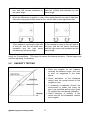
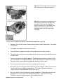
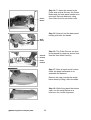
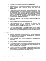
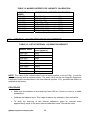
Adam Equipment
PGW PRECISION BALANCES
SERVICE MANUAL
ADAM EQUIPMENT CO. LTD.
P.N. 8236, Rev. A7, April 2007
@Adam Equipment Company 2007
@Adam Equipment Company 2007
CONTENTS
1.0 INTRODUCTION ..........................................................................................................3
2.0 DESCRIPTION OF CONSTRUCTION..........................................................................4
2.1
PRINCIPLE OF OPERATION................................................................................4
2.2
MODEL DIFFERENCES .......................................................................................6
2.3
INTERNAL CALIBRATION BALANCES................................................................7
2.4
EQUIPMENT AND TOOLS REQUIRED................................................................8
3.0 COMMON FAULTS .....................................................................................................9
4.0 TROUBLE-SHOOTING GUIDES ...............................................................................10
5.0 FUNCTIONAL TESTS AND ADJUSTMENTS............................................................13
5.1
REPEATABILITY TESTING AT INTERNAL CALIBRATION MASS ....................13
5.2
REPEATABILITY TESTING AT FULL CAPACITY ..............................................14
5.3
ECCENTRIC LOADING TESTING ......................................................................15
5.4
LINEARITY TESTING .........................................................................................17
6.0 MECHANICAL REPAIRS ..........................................................................................19
7.0 DEALER PARAMETERS ..........................................................................................25
8.0 INTERNAL CALIBRATION MASS ADJUSTMENT....................................................28
9.0 CABLES AND CONNECTIONS ................................................................................30
10.0 BALANCE MENU DIAGRAMS..................................................................................31
11.0 BALANCE DIAGRAMS ............................................................................................34
11.1 EXPLODED VIEW...............................................................................................34
11.2 MAIN MECHANICS ASSEMBLY.........................................................................35
@Adam Equipment Company 2007
1
@Adam Equipment Company 2007
2
1.0
INTRODUCTION
The PGW series of precision balances are very precise measuring devices used in the
laboratory conditions.
To achieve precise measurements you should make sure the balances are used in
suitable environments and the conditions are as described in the Operators Manuals.
There are no user serviceable parts in the balance. All service and internal calibrations
should be done only by Service Personnel trained and approved by Adam Equipment.
•
•
•
•
•
•
•
•
•
•
FEATURES:
• Large easy to read LCD display with
backlight
• Standard applications include Weighing,
Check weighing, Percentage Weighing,
Parts Counting, Animal/ Dynamic Weighing,
Net/Total and Density Determination
• Internal Calibration using motorised internal
calibration weight
• External calibration models available
• Bi-directional RS-232 interface
• Can be configured to print a GLP Compliant
report after each calibration to include the
PGW series
time, date, balance number and a
verification of the calibration
Automatic temperature compensation
Display in 4 languages- English, French, German and Spanish
18 weighing units
Capacity tracker
Date and time
Easy to use, sealed keypad
Below balance weighing facility
Password protection
Security locking point
Robust metal casing
@Adam Equipment Company 2007
3
2.0
DESCRIPTION OF CONSTRUCTION
2.1
PRINCIPLE OF OPERATION
The PGW balances use an electro-magnetic force restoration (or force motor) type
mechanics that converts a force generated due to an unknown mass placed on the
weighing pan into a voltage which can be measured by a high-precision voltmeter.
The force restoration system uses a magnet section along with a coil to convert a current
through the coil into a force. This force will balance the force caused due to the unknown
mass on the balance pan. This is accomplished in a system using a method of applying
the force from the unknown mass on one end of a beam and balancing it with the force
generated due to the current in the coil on the opposite end. The balance position is
detected by an optical detector connected to the beam.
When the mass is placed on the balance pan, the beam will be moved out of its original
null position. This movement is detected by the optical sensor. An amplifier connected to
the sensor will change the current through the coil, to force the beam to go back to its null
position. The amount of change in the current through the coil is proportional to the
unknown mass on the pan. The current passes through a precision resistor, creating a
voltage that is measured by the A/D converter.
Mechanical parts surrounding the balance beam make the force generated due to the
unknown mass go in a straight line through the balance beam, thus eliminating any
differences, depending upon the location of the mass on the balance weighing pan.
The electronics measure the voltage using precision amplifiers, A/D converter with high
resolution and a microprocessor working with memory, displays and power supply.
The microprocessor uses information from the A/D converter, a separate temperature
sensor & A/D converter for measuring the magnet temperature and the internal program to
determine the weight of the unknown mass and all other information to be displayed.
The system uses special programs to correct any temperature variations in the
mechanism. The balance is tested and calibrated at extreme temperatures and the details
are stored in the memory. These details are used to compensate for temperature changes
inside the balance due to self heating and ambient conditions.
The internal calibration models include an internal calibration weight controlled by the
microprocessor. This weight is not accessible by the user. Calibration can be performed
when the temperature sensor detects a change in the pre-set temperature (or the pre-set
time) either automatically or by manually entering in to the Calibration Menu.
@Adam Equipment Company 2007
4
ELECTRONICS MODULES
Within the balance there are electronic modules for:
•
Main PCB assembly including analogue circuit
•
Interface PCB assembly includes power supplies & RS-232 circuits
•
Display PCB
•
Calibration motor system (for internal calibration models)
PRINCIPLES OF BALANCE MECHANISM:
Details of the operation of the balance are found in the PGW User Manual.
@Adam Equipment Company 2007
5
2.2
MODEL DIFFERENCES
The PGW Series of balances have capacities that vary from 150g to 4500g. The basic
electronics and software are identical, the only differences between the models are:
•
Value of current sense resistors are selected to optimise the voltage to the A/D
converter.
•
The flexures- See Table 1 for details.
•
Pan support springs or leaf springs.
•
The external and internal calibration models- the internal calibration models are
available with motorised internal calibration as series denoted with ‘i’. The same
models are available with external calibration facility as series denoted with ‘e’.
•
All other changes are set by parameters stored in memory and set at the factory by
the manufacturer and can not be modified outside the factory.
TABLE 1: LIST OF FLEXURES
Flexures
(for 0.01g models)
Flexures
(for 0.001g models)
Horizontal x 8
Puller x 1
Pivots x 2
NOTE: To order for spare flexures, refer to Table: 14
at the end of this manual.
@Adam Equipment Company 2007
6
2.3
INTERNAL CALIBRATION BALANCES
The mechanism for controlling the internal calibration mass consists of:
-Internal calibration masses (1)
-Retaining Plates (2)
-Lever for mechanism (3) to move the masses
-Electrical motor (4) with cam (5) operated from the microprocessor
-Motor Bracket (6)
-Position Sensor (7)
-Weight hanger (8)
-Plastic weight lifter (9)
2
7
1
6
9
4
8
5
3
1
2
Exploded view of Internal Calibration Mechanism for PGW with 0.001 readability
NOTE: For PGW with 0.01 readability, components number 1 & 2 vary from the above,
the rest of the components are same.
Internal Calibration process can be started by user (using calibration menu and selecting
the internal calibration option) or automatically when the time or temperature of the system
changes by a pre-set value with respect to the time or temperature of last calibration.
Automatic Calibration function can be disabled by the user in the calibration sub-menu.
@Adam Equipment Company 2007
7
2.4
EQUIPMENT AND TOOLS REQUIRED
The following tools and equipment may be helpful when working on the balance.
GENERAL TOOLS AND EQUIPMENT
Screwdriver Philips
Screwdriver Medium Flat
Allen Hex Keys3 mm
4 mm
Needle Nose Pliers
Soldering iron
Precise square
Slide calliper
magnifier X10
Voltmeter
Oscilloscope
SPECIAL TOOLS AND EQUIPMENT
Weighing mass OIML Class F1
Calibration and test masses should be
used that will cover the weighing range
of thee balance to be tested. The
masses should be of high accuracy or
the actual mass should be known if less
accurate masses are used.
A Constant Temperature Chamber or
alternatively, a room capable of holding
a steady temperature of ±1°C and a
differential temperatures of minimum
10ºC and have a suitable table or
platform for the balances to be stable
for
performing
the
temperature
compensation. This is required if the
memory is cleared, wrong temperature
compensation values are used or if the
magnet has been modified. Repair of
flexures normally do not require
temperature compensation. See Table
9 details.
Suitable place for temperature tests
@Adam Equipment Company 2007
8
3.0
COMMON FAULTS
Faults associated with these balances leading to inaccurate weighing are generally of the
following types.
a. Calibration and Linearity faults
b. Mechanical faults
c. Electronics faults
A general troubleshooting section follows in section 4.0.
In order to know if a balance is working properly, it will be necessary to carry out some
performance tests on the balance. See section 5.0 for the details.
A brief description of the mechanical adjustments is covered in section 6.0.
In most cases, the first thing to be considered as a part of trouble-shooting is the software
parameters as this is the main method used to set calibration and linearity, set parameters,
view temperatures sensor values and perform the most basic of calibration functions. See
section 7.0 to enter the Dealer Parameter Settings.
Faults associated with these balances leading to inaccurate weighing are generally of the
following types.
a. Calibration and Linearity faults (See section 5.0 & 7.0)
b. Mechanical faults (See section 6.0)
c. Electronics faults (See the note below)
NOTE: The Electronics modules within the balance are not serviceable. In case of
any electronics component failure, contact your supplier.
@Adam Equipment Company 2007
9
4.0
TROUBLE-SHOOTING GUIDES
Service of a balance will generally be necessary when the balance does not perform as
expected. The balances are not user-serviceable. Problems usually fall into one of the
following categories:
User Problems:
The user is asking the balance for something it cannot do or is confused by the modes and
functions of a balance. It is also possible the user has set a parameter that has affected
the balance operation. Resetting the parameter to a normal value will restore operation.
Mechanical Problems
The balances consist of complicated and fragile mechanical devices. They can be
damaged by placing a weight on it which is too high for the balance or by dropping the
balance or occasionally shipping it without taking care. The most fragile parts are the
flexures.
Dust, dirt, spills and other foreign objects in the balance can also cause
problems.
Electronic Problems:
These are the rarest of the problems affecting balances. If an electronic problem is
suspected make sure the mechanical problems that can cause similar symptoms have
been eliminated before attempting electronic repairs. With the exception of cables most
electronic repairs are solved by PCB replacement. The Electronics modules within the
balance are not serviceable. In case of any electronics component failure, contact your
supplier.
The following table provides a guideline on the common problems. Note that many
problems may have multiple solutions and there may be problems found that are not listed
in the table. For more Information, contact your supplier.
TABLE 2: TROUBLE-SHOOTING
BALANCE DOES NOT FUNCTION
Problems
Possible causes
Suggestions
The balance is dead
when power is applied
Power supply failure
Check adapter is working
Cable / Connector
failure
Check adapter is correct for the balance
Normal adapter is 15VDC, 800mA.
*Power supply circuit board failure
*Short circuit on any circuit board
The display does not turn
on but the calibration
motor moves when
power is applied
Power is getting to
balance, display is not
working
@Adam Equipment Company 2007
10
*Display cables may be faulty
*Display module failure
The display stays on the
initial test screen when
power is applied.
Calibration weight motor
is on.
Unstable balance
Balance not working
correct
Power supply
*Check if balance is stable by using service
menu and view A/D values
Put draught shield over pan
Check power supplies
BALANCE WORKS BUT IS NOT STABLE
Balance is unstable by a
few divisions
Noise or vibration from
environment
Friction in mechanics
Check the balance is positioned correctly to
avoid vibration, wind or air movement, it is
on a solid table, It is not near sources of
heat or cool air,
Check balance with weights if problem
occurs when sample is used. Static
electricity on the samples can cause drifting
and instability.
Check the area around the weighing pan for
hair, dust, obstructions under the pan,
*A complete inspection of the mechanics to
look for sources of friction may be needed.
Balance is very unstable
and does not weigh
correctly
Mechanical problems
Balance programming
Check whether the temperature is changing
or there is a draught.
*A complete inspection of the mechanics to
look for sources of friction.
*Verify the A/D is also unstable. If the A/D
is OK then suspect the programming of the
balance. Reset parameters, check
temperature compensation, and redo the
calibration.
Electronic problems
Some electronic problems can also cause
this. But all mechanical problems must be
resolved first.
BALANCE IS NOT ACCURATE
You must have accurate and trusted weights to test a balance. If you suspect that the balance is
not accurate then you must know your weights are accurate. A balance calibrated using a bag of
flour is not accurate even if it works OK otherwise.
Balance is not accurate
Repeatability
Verify the balance shows the same value
when the same mass is placed on the
centre of the pan for a few tests.
Eccentric loading
Verify the balance shows the same reading
(within a tolerance depending upon the
model) when a mass is placed at positions
around the pan.
Linearity
Poor Repeatability
Verify the balance is acceptable throughout
the weighing range. The balance must give
acceptable readings from low weights up to
the capacity.
Usually a mechanical
problem.
Inspect the area around the pan for hair,
dust or other obstructions,
*Inspection of the mechanics may be
@Adam Equipment Company 2007
11
needed for any possible problems.
Poor Eccentric loading
A mechanical problem
Inspect the area around the pan for hair,
dust or other obstructions,
*Inspection of the mechanics may be
needed for any possible problems.
*Readjusting of the Eccentric loading is
recommended.
Poor Linearity
Usually a mechanical
problem
Re-check repeatability
*Inspection of the flexures for damage or
loose hardware may be required
*Use the Linearity Function in the service
menu to reset linearity
Electronic Problems
*A problem in the analogue circuit board or
power supplies can cause poor linearity.
Make sure all mechanical problems have
been eliminated first
OTHER PROBLEMS
Cannot calibrate
Zero shifted more than
allowed
*Check all flexures for damage
*Reset factory calibration
*Verify linearity and repeatability
Calibration timeout
*The balance may be unstable. Verify
stability as above. Try using a more
aggressive filter
Calibration weight motor
does not stop
*Check the cables to the motor, try plugging
the balance into the power again
*Look for friction in the calibration weight
movement
*Check the opto-coupler that controls the
motor position.
RS-232 not working
Doesn’t print
Check parameters match the device
connected
Verify cable is correct
*RS-232 circuits damaged
Display dark, keys beep
Display contrast poor
*Check the cables to the display
Cable damaged
*Replace display-it may be damaged
LCDs on the display are
faulty or damaged
*To be carried out by authorised technicians only.
5.0
@Adam Equipment Company 2007
12
FUNCTIONAL TESTS AND ADJUSTMENTS
In order to know if a balance is working properly, it will be necessary to carry out the
following tests on the balance. These tests should be performed initially, when it is not
clear whether there is any problem with the balance. These tests should also be performed
anytime a balance has been serviced or any changes are made.
Before performing the tests the balance should be allowed to warm-up in a stable
environment for a minimum of 4 hours. During this time the following should be checked:
•
Install the pan supports, the pan and the breeze-shield, if applicable and make
sure they do not interfere with correct weighing.
•
Level the balance.
•
Verify all the keys work properly and the functions set are suitable for the
balance to be tested. For example, set to grams weighing, all digits operating
normally, the filters set to a normal setting, etc.
•
Verify the RS-232 is operating correctly using a communications program.
•
Verify the display is correct, the minus sign is shown, decimal points are in the
correct position, the weighing unit is correct and the stability symbol is correct.
•
Verify the calibration is functioning correctly.
For better accuracy, we suggest to use only the Class F1 weights during the linearity
adjustment. The maximum permissible errors of F1 weights are given in the Table below.
TABLE 3: OIML R-111 TEST WEIGHT TOLERANCES
5.1
Value of Class
F1 weights
Maximum
Permissible Error
Value of Class
F1 weights
Maximum
Permissible Error
5000 g
2000 g
1000 g
500 g
200 g
± 0.025 g
± 0.010 g
± 0.005 g
± 0.0025 g
± 0.0010 g
100 g
50 g
20g
10g
± 0.0005 g
± 0.0003 g
± 0.25 mg
± 0.020 mg
REPEATABILITY TESTING AT INTERNAL CALIBRATION MASS
Repeatability is checked at the approximate value of the internal calibration mass.
•
•
•
•
•
Perform automatic calibration.
Place the right weighing mass on the pan as shown in the table below.
Repeat this procedure 5 times.
Compare the reading results with the actual mass.
Compare results, the readings with the mass on the pan should agree within
the acceptable error as shown.
@Adam Equipment Company 2007
13
TABLE 4: REPEATABILITY ERRORS AT INT. CAL. MASS
5.2
Balance model
PGW 153
PGW 253
PGW 453
Mass
100g
240g
240g
Acceptable error
± 0,002 g
PGW 753
520g
± 0,002 g
PGW 1502
1400g
± 0,02 g
PGW 2502
1400g
± 0,02 g
PGW 3502
1400g
± 0,02 g
PGW 4502
1400g
± 0,02 g
± 0,002 g
± 0,002 g
REPEATABILITY TESTING AT FULL CAPACITY
•
•
•
•
•
Place the mass on the pan as shown in the table below.
After stabilization record the reading.
Take off the mass and after stabilization record the reading with no mass on
the pan.
Repeat 5 times.
Compare results, the readings with the mass on the pan should agree within
the acceptable error as shown.
TABLE 5: REPEATABILITY ERRORS AT FULL CAPACITY
Balance model
PGW 153
PGW 253
PGW 453
Mass
150g
250g
450g
Acceptable error (S.D.)
± 0,002 g
PGW 753
750g
± 0,002 g
PGW 1502
1500g
± 0,02 g
PGW 2502
2500g
± 0,02 g
PGW 3502
3500g
± 0,02 g
PGW 4502
4500g
± 0,02 g
± 0,002 g
± 0,002 g
REPEATABILITY ADJUSTMENT:
If the errors are still not acceptable, refer to section 7.0 for adjustment.
@Adam Equipment Company 2007
14
5.3
ECCENTRIC LOADING TESTING
•
•
•
•
•
•
Check the balance readings in the positions marked.
Place the mass shown in the table below at the center of the pan.
After stabilization, record the value.
Move the mass to the next point, half way between the center and the edge of the
pan.
Record the results for each point.
The readings on the edges should match with the reading at the center point within
the tolerances shown.
TABLE 6: ECCENTRIC LOADING ERRORS
Balance model
PGW 153
PGW 253
PGW 453
Mass
50g
100g
200g
Acceptable error
± 0,002 g
± 0,002 g
± 0,002 g
PGW 753
400g
± 0,002 g
PGW 1502
500g
± 0,02 g
PGW 2502
1000g
± 0,02 g
PGW 3502
1000g
± 0,02 g
PGW 4502
1000g
± 0,02 g
If the differences in the weighing values at the 5 locations are bigger than ±5 divisions, you
need to adjust the balance for Eccentric loading.
ECCENTRIC LOADING ADJUSTMENT:
These adjustments will result in moving the mounting points for the flexures so that the
mechanical assembly is set right to produce the same weighing results regardless of the
position of the mass on the weighing platform.
The adjustment is done using the hex head bolts on the mechanics: The amount of
adjustment and the direction by which the screws are turned will depend on the amount of
error observed as the mass is moved around the platform.
@Adam Equipment Company 2007
15
Hexagonal
Screws
•
•
•
•
•
•
•
•
Place the balance on a suitable and stable surface.
Take off the cover of the balance. Do not unplug the display cable.
Mount the pan on the pan supports.
Locate the hexagonal screws to adjust the eccentric loading.
Always adjust for the largest differences first, i.e., either the difference in
value when the mass is placed at back to front or that of side to sidewhichever difference is the largest should be adjusted first.
Re-check the readings after each adjustment. For small corrections the bolts
will be turned by very small angles.
The value of the mass used for adjustment should be of 1/3 to ½ of the
balance capacity.
When placing the mass on the pan, locate it at ½ the distance from the
centre to the edge.
Refer to the following instructions for detailsA. When the difference is greater in case of back to front of the pan than that of side
to side, do the front to back adjustment first -
@Adam Equipment Company 2007
16
If the reading is more at the front,
turn both the screws clockwise by
the same angle.
If the reading is more at the back, turn
both the screws anti-clockwise by the
same angle.
B. When the difference is greater in case of the mass placed from side to side than
that of the mass placed from back to front, do the side to side adjustment first -
If the reading is more at the right side
of the pan, turn the left screw anticlockwise and the right screw
clockwise by the same angle.
If the reading is more on the left side of
the pan, turn the left screw clock-wise
and the right screw anti-clockwise by the
same angle.
After setting the adjustment, you should place the balance to one side for some time and
weigh on it occasionally. This helps to reduce the internal tensions. Re-test again and
continue adjusting, if necessary.
5.4
LINEARITY TESTING
• Place the weights on the balance
covering the balance range- from min
to max, as suggested in the table
below.
• Check deviations of the displayed
values from the actual values on the
weights on pan.
• If necessary re-calibrate. Ensure the
environment is stable, the warm up
time is as specified and only the Class
F1 weights are used during calibration.
• Check accuracy of linearity. If the
values are still not acceptable, contact
your supplier.
@Adam Equipment Company 2007
17
Examples of the weights that can be used for testing are given in the following table:
TABLE 7: SUGGESTED MASS FOR THE LINEARITY TESTING
PGW 153
10g
20g
30g
PGW 253
20g
50g
PGW 453
50g
PGW 753
40g
50g
60g
80g
100g
120g
150g
80g
1000g 120g
150g
180g
200g
220g
250g
100g
120g
150g
200g
250g
300g
350g
400g
450g
100g
200g
250g
300g
400g
450g
500g
600g
700g
750g
PGW 1502
100g
200g
300g
400g
500g
600g
800g 1000g 1200g 1500g
PGW 2502
500g
600g
800g 1000g 1200g 1500g 1700g 2000g 2200g 2500g
PGW 3502
500g
600g
800g 1000g 1200g 1500g 2000g 2500g 3000g 3500g
PGW 4502
500g 1000g 1200g 1500g 2000g 2500g 3000g 3500g 4000g 4500g
It is necessary to know the values of the masses used to an accuracy that is better
than the balance weighing results. NOTE: The accumulation of errors when using
multiple masses can contribute to a larger apparent error. Refer to Table 3. If you are
using 200g & 50g masses to make 250g, there may be an accumulated error of
(0.0010g + 0.0003g) 0.0013g.
The error at each value is determined by computing:
Error = Displayed mass – actual mass
TABLE 8: LINEARITY ERRORS
Balance model
PGW 453
Acceptable error
±0.003g
±0.003g
±0.003g
PGW 753
±0.003g
PGW 1502
±0.03g
PGW 2502
±0.03g
PGW 3502
±0.03g
PGW 4502
±0.03g
PGW 153
PGW 253
LINEARITY ADJUSTMENT:
If the values are still not acceptable, refer to section 7.0 for Linearity adjustment.
@Adam Equipment Company 2007
18
6.0
MECHANICAL REPAIRS
The mechanical repairs which are normally required will be:
-Replace broken or damaged flexures
-Cleaning or replacing of magnet and drive coil
Each of these is explained in the following section.
The part numbers for ordering the components needed during the repair are listed in the
Annexure at the end (see Table 13).
Step 1: To open the PGW Balance,
first remove the two screws on the
rear panel using the 2.5mm Allen Hex
Keys.
Rear Screw 1
Rear Screw 2
Step 2: Remove the stainless steel
pan and the 4 rubber pan supports.
Stainless
Steel pan
Rubber pan
support
Step 3: Hold the balance up side
down and remove the 2 front screws
using the 3mm Allen Hex Keys.
2 bottom screws
Step 4: Next you will need to remove
the top saddle by removing the two
screws using the 3mm Allen Hex
Keys. Remove the pan support
spacers.
3 mm Allen
Hex Keys
Top saddle
@Adam Equipment Company 2007
19
At this stage the balance is ready to
be opened as shown in the next step.
Step 5: Press the spirit level lug
downwards with one hand and lift the
top case with the other hand.
Spirit Level
Lug
Display
Cable
Step 6: To detach the top case,
remove the Display Cable and the
Keypad Cable from the main PCB.
Keypad
Cable
Step 7: To detach the top pan support
bracket from the Mechanics, use the
3mm Allen Hex Keys to remove the 2
screws
Top pan
support
bracket
Flexures
Magnet
cover
Mechanics
@Adam Equipment Company 2007
20
You can view the Mechanics with the
top horizontal flexures and the magnet
with cover.
Step 8: If you need to clean the Drive
Coil and the magnet, remove the 2
screws attached to the magnet cover
using the 4mm Allen Hex Keys.
Magnet
Cover
Square
Tool
Step 9: It is suggested to add the
Square Tool at this stage to protect
the flexures from getting damaged
during any repair work.
Step 10: Unsolder the Drive Coil
Wires. Note the position of the coil
drive wires on the board to remove the
mechanics from the case. If not reconnected correctly, the balance will
not work.
Step 11: Next you will need to remove
the bottom case. Turn the balance up
side down and remove the 3 screws
using the 3mm Allen Hex Keys.
@Adam Equipment Company 2007
21
Step 12: Lift the case carefully leaving
the mechanics on the work surface.
Step 13: If you need to change any of
the flexures hold the assembly firmly
as shown. Remove the damaged
flexure by using the 3 mm Allen Hex
Keys and fix the new one. Fix the
assembly back into the base when
complete.
If you need to replace any flexure, the following guidelines may help.
•
Replace only with the correct flexure procured from Adam Equipment. See table
1 for details
•
If possible only replace one flexure at a time.
•
Keep all flexures aligned vertically, horizontally and from front to back.
•
The active area of a flexure must align with the active area of all other flexures in
the same axis.
•
Do not over-tighten the flexure screws. Residual stress is often a cause of drift
with temperature or unstable readings. When tightening the screws work slowly
from one screw to the others to tighten all screws a little at a time.
•
Do not allow the flexures to twist when tightening the screws.
•
Be certain you are using the correct flexures for the balance. Many flexures look
very similar but have different applications. The major difference between
similar flexures is the thickness of the active area.
•
Be very careful not to bend flexures during installation. Remember flexures are
designed to be very weak in the direction they bend. They are not strong
enough to support a large weight in the bending direction.
@Adam Equipment Company 2007
22
Power
Board
Step 14: To have the access to the
Puller and vertical flexures, the Power
Board and the back panel needs to be
removed. Remove board by using
3mm Allen Hex Key as shown here.
Step 15: Next pull out the back panel
holding with both the hands.
Back
Panel
Vertical
Flexure
Step 16: The Puller Flexure can then
be accessed for repair as shown here.
Use the 3mm Allen Hex Key
Puller
Flexure
Step 17: After all repair work is done,
follow the steps backwards to reassemble the balance.
Remove the cap covering the weigh
below hook by lifting it from the base.
Step 18: While fixing back the bottom
case, use the weigh below as a
reference for correct alignment.
@Adam Equipment Company 2007
23
Step 19: Ensure the weigh below is in
the exact centre of the hole provided
for installing the hook.
Step 20: After the repair it is
suggested that the balance is
Temperature-calibrated using a
Constant Temperature Chamber or in
a suitable room, particularly for few
cases as described in Table 9.
PGW Inside a Constant Temperature Chamber
TABLE 9: GUIDELINE FOR TEMPERATURE COMPENSATION
REPAIR UNDERTAKEN
Calibration Performed
Linearity adjusted
Eccentric Loading adjusted
Flexures repaired or replaced
Magnet and/or drive coil cleaned
Magnet and/or drive coil replaced
Temperature sensor replaced
Data erased or amended
PCBs replaced
@Adam Equipment Company 2007
REMARKS ON TEMP. COMPENSATION
Not required
Not required
Not required
Normally not required
Not required
Must be done
Must be done
Must be done
Must be done
24
7.0
DEALER PARAMETERS
The parameters available to the users are described in the User Manual in details. This
section describes the parameters available to the dealers for setting up the balance.
Access to these parameters is controlled by password.
•
From the supervisor menu, select the PASSCODES option.
•
From the PASSCODES menu, select the OPERATOR option.
•
Enter the dealer passcode, which is 41218 (DLR as D=4th L=12th R=18th
letter of the alphabet). Press [Setup/Enter].
•
Press the [Mode] key three times, or press the [Esc] key to return to
weighing and then the [Setup/Enter] key to return to the outer level menu,
which now displays “SUPERVISOR”.
•
From this menu select the DEALER option.
Available options on the dealer menu are:
1. ADC COUNTS
The balance displays the averaged, temperature compensated and linearity corrected
weight ADC counts in the small digits and the spread of the last 50 readings in the large
digits.
•
Pressing the [Unit] key switches the display between the weight and
temperature ADC counts.
•
Temperature counts display is indicated by a ‘T’ symbol and shows the
individual temperature ADC counts in the small digits and the average of
the last 10 readings in the large digits.
•
Pressing the [Setup/Enter] or [Mode] key escapes to the next item on the
dealer menu.
•
Pressing the [Esc] key returns to weighing.
TABLE 10: WEIGHT ADC
Zero Setting
Maximum Linearity Load
(See Table 8)
ADC
Range
> 500,000
< 16,000,000
0.5 to 1.5 million
14 -16 million
@Adam Equipment Company 2007
25
TABLE 11: MAXIMUM LINEARITY LOAD
BALANCE MODEL
MAXIMUM LINEARITY LOAD
PGW 153
PGW 253
PGW 453
PGW 753
PGW 1502
PGW 2502
PGW 3502
PGW 4502
160g
260g
475g
800g
1600g
2600g
3750g
4750g
2. DATA COMMS
• Displays “ACTIVE” when selected.
• Pressing the [Print] key sends the stored configuration data as a
formatted table with address headers to the RS-232 port at 9600 baud, 8
bits, no parity, irrespective of the settings chosen in serial setup on the
supervisor menu.
• Pressing the [Setup/Enter] or [Mode] key escapes to the next item on the
dealer menu.
• Pressing the [Esc] key returns to weighing.
3. CALIBRATE
This menu offers two options:
A. TEMP CAL
•
Select the LOW or HIGH temperature calibration point.
•
Enter the balance temperature (10 to 40 deg C).
•
If the low temperature calibration point is selected, the entered
temperature must be at least 10 degrees below the one stored for the high
temperature calibration point, otherwise the display will show “ERROR
HI”.
•
If the high temperature calibration point is selected, the entered
temperature must be at least 10 degrees above the one stored for the low
temperature calibration point, otherwise the display will show “ERROR
LO”.
•
If the entered temperature is within range, the display will show the
message “LOAD 0”.
@Adam Equipment Company 2007
26
•
Ensure that the weight pan is clear, then press [Setup/Enter].
•
After measuring the no-load weight, the display will prompt to load the
external calibration mass. Load the required mass and press
[Setup/Enter].
•
If temperature calibration at the other temperature has already been
performed successfully, after measuring the weight of the calibration mass
the instrument will display the current temperature correction in parts per
million per degree Celsius as “PPM CORR xxx” until any key is pressed
to return to the TEMP CAL menu option. If temperature calibration at the
other temperature has not been performed, the instrument will return
immediately to the TEMP CAL menu option.
•
Pressing the [Mode] key at any time escapes back to the TEMP CAL
menu option.
•
Pressing the [Esc] key at any time returns to weighing.
•
If any measurement errors are encountered, an appropriate error
message will flash on the display until any key is pressed, when the
instrument will return to the TEMP CAL menu option.
•
If any errors are encountered or the [Mode] or [Esc] keys are pressed
during temperature calibration, the procedure will be aborted with no new
data stored, and any previous temperature correction data will be retained.
B. LINEAR CAL
•
Display will ask to load the required weights in turn. Place the weights onto
the weighing pan in turn and press the [Setup/Enter] key. Please note
that the weights are not selectable
•
Pressing the [Mode] key at any time escapes back to the LINEAR CAL
menu option.
•
Pressing the [Esc] key at any time returns to weighing.
•
If any measurement errors are encountered, an appropriate error message
will flash on the display until any key is pressed, when the instrument will
return to the LINEAR CAL menu option.
•
If any error is encountered or the [Mode] or [Esc] keys are pressed during
linearity calibration, the procedure will be aborted with no new data stored
and any previous linearity calibration data will be retained.
@Adam Equipment Company 2007
27
TABLE 12: MASSES NEEDED FOR LINEARITY CALIBRATION
BALANCE
MODEL
PGW 153
PGW 253
PGW 453
PGW 753
PGW 1502
PGW 2502
PGW 3502
PGW 4502
8.0
MASSES FOR LINEARITY CALIBRATION
10g, 20g, 30g, …….….up to 160g
20g, 40g, 60g,………...up to 270g
25g, 50g, 75g,………...up to 475g
50g, 100g, 150g, ….….up to 900g
100g, 200g, 300g, .….up to 1600g
200g, 400g, 600g…....up to 2700g
250g, 500g, 750g,.…..up to 3750g
250g, 500g, 750g…....up to 4750g
INTERNAL CALIBRATION MASS ADJUSTMENT
TABLE 13: LIST OF INTERNAL CALIBRATION WEIGHTS
PGW 153i
PGW 253i
PGW 453i
Internal Calibration
mass (approx.)
100g
240g
240g
PGW 753i
520g
PGW 1502i
1400g
PGW 2502i
1400g
PGW 3502i
1400g
PGW 4502i
1400g
Balance model
NOTE: The value of the internal mass is not an exact number, such as 100g. It must be
set by comparing with an external mass. The exact value can be set using the Supervisor
Parameter section as described in the User Manual (section 13.5), provided this feature is
enabled at the factory.
PROCEDURE
•
Make sure the balance is level and has been ON for 4 hours or more at a stable
temperature.
•
Calibrate the balance twice. This helps to reduce any stresses in the mechanics.
•
To verify the accuracy of this internal calibration, place an external mass
approximately equal to the same internal calibration mass. Record the result.
@Adam Equipment Company 2007
28
•
Enter the Internal Calibration section using the Supervisor passcode as per the
following procedure-
•
Pressing the [Setup/Enter] key while in normal weighing gives access to the
Supervisor Menus.
•
When [Setup/Enter] is pressed and passcodes are not enabled the display will
show the Supervisor menus. If passcodes are enabled, the balance will ask for it by
displaying “PASSCODE 0”
•
If a wrong code is entered an “ERROR CODE” message will flash and the balance will
return to weighing mode
•
If the passcode has been enabled and entered, the balance will allow the user to
access the Supervisor’s menus by which the user can enable/disable weighing units
or modes, set balance parameters for the conditions, set time and date, set
parameters for the RS-232 interface, calibration parameters and security
parameters
•
The display will show the first menu “UNITS”. The [Up] and [Down] keys will cycle
through the main menus, pressing the [Setup/Enter] key will enter the menu and
sub-menu or options can be set. Press [Mode] to come out of a sub-menu or [Esc]
to return to normal weighing
•
Press [Enter] when “CAL SETUP” is displayed to select the calibration parameters
•
The options for each parameter can be scrolled through by using the [Up] or
[Down] key
•
When “INT CAL” is displayed select “YES” by pressing the [Enter] key. . The value of
the internal mass set in the factory will be displayed
•
A new internal value can then be reset to make the external mass value display
correctly. If the reading for the external mass is greater than the actual value of the
mass then reduce the internal mass value by the difference. Enter this reduced
value when prompted by the display
For example, if the internal mass previously set is 520.054g and the display reads
500.050g when using an external mass of 500g, then reduce the internal mass
value by 0.050g. Enter the new revised value of 520.004 (in place of 520.054g)
when prompted. The adjustment can be done for up to ±100mg.
•
Repeat the calibration and check the value of the external mass again
•
Repeat this procedure until the value displayed is correct for the mass used
•
Press [Esc] to return to normal weighing
@Adam Equipment Company 2007
29
9.0
CABLES AND CONNECTIONS
@Adam Equipment Company 2007
30
10.0 BALANCE MENU DIAGRAMS
@Adam Equipment Company 2007
31
@Adam Equipment Company 2007
32
@Adam Equipment Company 2007
33
11.0 BALANCE DIAGRAMS
11.1 EXPLODED VIEW
Stainless
Steel pan
Pan Support
Assembly
Pan Support
Spacers x 4
Power Supply
PCB
Mechanics
Main PCB
Magnet
Assembly
Balance
Casing
Foot
@Adam Equipment Company 2007
34
11.2 MAIN MECHANICS ASSEMBLY
Magnet Cover
Upper Horizontal
Beam
Main
Chasis
Optical switch
Off-Centre
Loading
Assembly
Coil Beam
Assembly
Magnet Assembly
Pivot
Puller
Lower
Horizontal Beam
Horizontal Flexure
@Adam Equipment Company 2007
35
ANNEXURE
TABLE 14: PGW SELECTED PART NUMBERS
COMPONENT
Main PCB
Filter PCB
Display PCB
Power PCB (includes RS-232)
Flexures for PGW 153, 253, 453 & 753 Horizontal x 8
Puller x 1
Pivots x 2
Flexures for PGW 1502, 2502, 3502 & 4502 Horizontal x 8
Puller x 1
Pivots x 2
Feet
Keypad
Stainless Steel Pan, 192 x 192mm
Stainless Steel Pan, 140 x 140mm
Pan Support Bracket
(for PGW 153, 253, 453 & 753)
Pan Support Bracket
(for PGW 1502, 2502, 3502 & 4502)
Rubber Pan Support (set of 4)
Anti-static Springs
Circlip (circular clip to retain the pan support
in place)
Power Supply Adapter
Square Glass Breeze Shield
Internal Calibration Motor
Internal Calibration Cam
Return Spring
Optical Position Sensor
(complete assembly)
Power Cable
Display Cable
Internal Cal Motor and Opto Cable
Temperature Sensor Cable
PART NUMBER
7067
8087
6095
7068
8665
8663
8664
8666
8665
8663
7064
7073
7074
7075
7052
7045
7047
7512
7242
7326
7449
7091
7094
7180
7033
7228
7234
7237
7191
NOTE:
Refer to the drawings for the item number corresponding to this list. If
spare parts are required identify the model number and serial number
of the balance. Contact your supplier for further details on price and
availability of all spare parts.
The circuit boards do not have user serviceable parts.
@Adam Equipment Company 2007
36
Manufacturer’s Declaration of Conformity
This product has been manufactured in accordance with the harmonised European standards,
following the provisions of the below stated directives:
Electro Magnetic Compatibility Directive 89/336/EEC
Low Voltage Directive 73/23/EEC
Adam Equipment Co. Ltd.
Bond Avenue, Denbigh East
Milton Keynes, MK1 1SW
United Kingdom
FCC COMPLIANCE
This equipment has been tested and found to comply with the limits for a Class A digital device,
pursuant to Part 15 of the FCC Rules. These limits are designed to provide reasonable protection
against harmful interference when the equipment is operated in a commercial environment. The
equipment generates, uses, and can radiate radio frequency energy and, if not installed and used in
accordance with the instruction manual, may cause harmful interference to radio communications.
Operation of this equipment in a residential area is likely to cause harmful interference in which case
the user will be required to correct the interference at his own expense.
Shielded interconnect cables must be employed with this equipment to insure compliance with the
pertinent RF emission limits governing this device.
Changes or modifications not expressly approved by Adam Equipment could void the user's
authority to operate the equipment.
WEEE COMPLIANCE
Any Electrical or Electronic Equipment (EEE) component or assembly of parts intended to be
incorporated into EEE devices as defined by European Directive 2002/95/EEC must be recycled or
disposed using techniques that do not introduce hazardous substances harmful to our health or the
environment as listed in Directive 2002/95/EC or amending legislation. Battery disposal in Landfill
Sites is more regulated since July 2002 by regulation 9 of the Landfill (England and Wales)
Regulations 2002 and Hazardous Waste Regulations 2005. Battery recycling has become topical
and the Waste Electrical and Electronic Equipment (WEEE) Regulations are set to impose targets
for recycling.
@Adam Equipment Company 2007
37
ADAM EQUIPMENT is an ISO 9001:2000 certified global organisation with more than 30 years
experience in the production and sale of electronic weighing equipment. Products are sold through
a world wide distributor network supported from our company locations in the UK, USA, SOUTH
AFRICA and AUSTRALIA.
ADAM’s products are predominantly designed for the Laboratory, Educational, Medical and
Industrial Segments. The product range is as follows:
-Analytical and Precision Laboratory Balances
-Counting Scales for Industrial and Warehouse applications
-Digital Weighing/Check-weighing Scales
-High performance Platform Scales with extensive software
features including parts counting, percent weighing etc.
-Crane scales for heavy-duty industrial weighing
-Digital Electronic Scales for Medical use
-Retail Scales for Price computing
Adam Equipment Co. Ltd.
Bond Avenue
Milton Keynes
MK1 1SW
UK
Adam Equipment Inc.
26, Commerce Drive
Danbury, CT
06810
USA
Adam Equipment S.A. (Pty) Ltd.
7 Megawatt Road,
Spartan EXT 22, Kempton Park,
Johannesburg
Republic of South Africa
Adam Equipment (S.E. ASIA)
Pty Ltd.
2/71 Tacoma Circuit
Canning Vale, Perth
Western Australia
Tel:+44 (0)1908 274545
Fax: +44 (0)1908 641339
Tel: +1 203 790 4774
Fax: +1 203 792 3406
Tel: +27 (0)11 974 9745
Fax: +27 (0)11 392 2587
Tel: +61 (0) 8 6461 6236
Fax: +61 (0) 8 9456 4462
E-mail:
[email protected]
E-mail:
[email protected]
E-mail:
[email protected]
E-mail:
[email protected]
© Copyright by Adam Equipment Co. Ltd. All rights reserved. No part of this publication
may be reprinted or translated in any form or by any means without the prior permission of
Adam Equipment.
Adam Equipment reserves the right to make changes to the technology, features,
specifications and design of the equipment without notice.
All information contained within this publication is to the best of our knowledge timely,
complete and accurate when issued. However, we are not responsible for
misinterpretations which may result from the reading of this material.
The latest version of this publication can be found on our Website.
Visit us at www.adamequipment.com
@Adam Equipment Company 2007
38