1
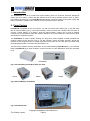
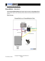
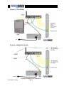
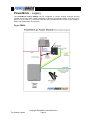
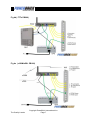
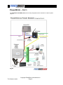
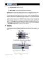
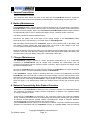
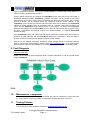
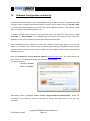
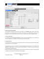
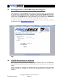
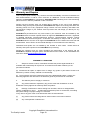
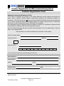
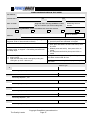
PB100/200 Manual For Network Service Technicians Version 1.9.5 PowerBrick International PO Box 68-266 Newton, Auckland 1021 New Zealand Phone: +064 9 3094403 Email: [email protected] Web: http://www.PowerBrick.net Service Manual Table of Contents 1. INTRODUCTION ......................................................................................................................... 4 2. FORM FACTORS ....................................................................................................................... 4 3. INSTALLATION W IRING OPTIONS ............................................................................................. 5-8 4. TERMINALS .............................................................................................................................. 9 5. SERVICE PRECAUTIONS .......................................................................................................... 10 6. BATTERY MAINTAINENCE ........................................................................................................ 10 7. CHARGER MAINTAINENCE ....................................................................................................... 10 8. NETWORK CONNECTIVITY AND AUTO REBOOT FUNCTION......................................................... 11 9. FAULT DIAGNOSIS ................................................................................................................... 12 10. MAINTAINENCE COMPLETION .................................................................................................. 13 11. TESTING FAILURES ................................................................................................................. 13 12. SOFTWARE CONFIGURATION AND SET UP ................................................................................ 13 13. DEVICE REGISTRATION ALARM INTERGRATION SUPPORT.......................................................... 22 14. ALTERATIONS AND ADDITIONS ................................................................................................. 22 15. W ARRANTY & REPAIRS ........................................................................................................... 23 16. REFUNDS ............................................................................................................................... 24 17. ACCESSORIES ........................................................................................................................ 24 18. ELECTRICAL SPECIFICATIONS.................................................................................................. 25 19. INSTALLER REGISTRATION & COMISSIONING SHEETS ............................................................... 25 Table of Figures 1, INTERNAL BATTERY POWERBRICK FORM FACTOR....................................................................... 3 2, EXTERNAL BATTERY POWERBRICK FORM FACTORS. .................................................................. 3 3, POWERBRICK MOUNTED............................................................................................................ 3 4A, B, C W IRING OPTIONS. ................................................................................................................... 4-8 5A, B POWERBRICK TERMINALS. ......................................................................................................... 9 6 FAULT FLOW CHART. ................................................................................................................ 11 7 REGISTRATION WEB SITE. ........................................................................................................ 22 Copyright PowerBrick International Inc The Quality Leader Page 2 Service Manual 1. Introduction The PowerBrick is used to provide and monitor battery power for Customer Premises Equipment (CPE) such as modems, routers and data switches that are using essential services such as Voice, Fire, Medical and Security. The PowerBrick automatically reports the status of the power supply and battery via email or TCP/IP to the customer or their monitoring service provider. 2. Form Factors PowerBrick is available in two form factors, one with an internal 7AHr battery (fig 1) and the other with an external battery (fig 2). The external battery version provides the customer with the option to connect a larger battery up to 60AHr, while the internal battery version can be wall or desktop mounted. Only PowerBrick models with external batteries can accommodate the exterior Solar panel accessories to supplement power. The PowerBrick is used to replace existing AC “plug pack” power supplies normally provided with existing network access devices such as 12v DC modems, routers and data switches. Should the network access equipment have a voltage requirement other than 12v DC, then this is provided using the appropriate DC-DC conversion lead. See Section 16 This document contains servicing information for the internal battery PowerBrick (fig 1) and external battery PowerBrick (fig 2) when located in a CPE enclosure or home distribution wiring box (example fig 3). PB12300W Fig 1 Internal Battery PowerBrick with rear View PB100 PB200 PB300 Fig 2 External Battery PowerBrick Fig 3 PowerBrick Hub Copyright PowerBrick International Inc The Quality Leader Page 3 Service Manual 3. Installation Wiring Options PowerBrick - Standard The standard PowerBrick ( PB100) includes basic functions such as a backup power system to support network access devices such as in Fig4a & Fig 4b-1/2 below. The PowerBrick checks communication regularly via the ONT/Router and will reboot devices automatically until comms is restored. Fig4a ( PB100 ) Copyright PowerBrick International Inc The Quality Leader Page 4 Service Manual Fig 4b-1 ( FTTx PB100 ) Fig 4b-2 ( xGSM/xDSL PB100 ) Copyright PowerBrick International Inc The Quality Leader Page 5 Service Manual PowerBrick – Legacy The PowerBrick Legacy (PB200) can be configured to convert existing analogue (POTS) medical and security alarm system messages to Ethernet thru the ISP Router via a ONT (FTTx shown in Fig 4c,4d & 4e ) or directly to the ISP using a GSM Wireless or DSL copper interface. (xDSL and xGSM shown in Figure 4e) Fig 4c PB200 Copyright PowerBrick International Inc The Quality Leader Page 6 Service Manual Fig 4d ( FTTx PB200) Fig 4e ( xGSM/xDSL PB200) Copyright PowerBrick International Inc The Quality Leader Page 7 Service Manual PowerBrick - Alarm The PowerBrick ALARM (PB300) can be fully integrated as the customers’ IP alarm system (Fig 4f) Fig 4f Copyright PowerBrick International Inc The Quality Leader Page 8 Service Manual PowerBrick installation options are; a) PB100 “STANDARD” UPS for CPE only b) PB200 “LEGACY” UPS for CPE with Analogue Alarm Media Convertor c) PB300 “ALARM” UPS for CPE with Integrated IP Alarm Support PowerBrick devices are often pre-installed at the customer’s premises and may include a fully featured integrated IP alarm system (Fig 4f ). These devices will carry a Telco approval sticker. The PowerBrick 12 volt DC connector will operate exactly like a PowerBrick Basic device. It is recommended that in new Fibre to the Home (FTTH), Copper to the Home (CTTH) or Wireless to the Home (WTTH) building projects, that a complete integrated PowerBrick ALARM be used as a replacement to the traditional analogue alarm system. The Ethernet patch cable between the PowerBrick and the customer’s router is required to send battery alert email messages to the customer or monitoring service provider to maintain an improved customer experience. It is highly recommended that this Ethernet patch cable is required to be connected to ensure the network access equipment (modem/routers) are more reliable as the PowerBrick will automatically detect network interruptions and reboot the equipment without customer intervention. The installer or customer can register their PowerBrick at http://WWW.PowerBrick.Net by completing the online Web form. 4. Terminals The terminals and wiring on the standard PowerBrick and PowerBrick Legacy as shown in fig 5a (external battery) and fig 5b (internal battery) are identical except that the external battery version has the extra battery connector and the Alarm input and POTS output is Blank. ( not used) Fig 5a PB200 ( Wiring Distributor Model) Fig 5b PB200W ( Desktop Version) Copyright PowerBrick International Inc The Quality Leader Page 9 Service Manual 5. Service Precautions Observe antistatic precautions. On commercial sites advise the Telco of any entry into the PowerBrick enclosure. Isolate the cabinet AC power and remove the battery terminals before disassembling any part of the unit. 6. Battery Maintenance The PowerBrick battery requires minimal routine maintenance as it is continuously connected to PowerBrick.Net or local partner CMS to inform the customer about battery issues well before it becomes a serious problem. When only connected to PowerBrick.Net all battery fault conditions are automatically sent via TXT or Email to the battery service contractor (and/or customer). The battery should be tested as detailed below. Disconnect the battery and record open circuit charge voltage of the PowerBrick battery terminals and If it is not between 13.4-13.8Vdc refer to “Fault Diagnosis” With the battery disconnected from PowerBrick, apply a “4 amp dummy load” to the battery and note battery terminal voltage with load applied after 15 seconds. If this voltage is less than 11.5Vdc replace the battery and date and initial the new one. Remove the dummy load from the battery and note battery terminal voltage after 5 seconds. If this voltage is more than 2vdc above the voltage read with load applied then replace the battery and record the date on the new battery casing with a permanent marker pen. 7. Charger Maintanance The PowerBrick charger requires no routine preventive maintenance as it is continuously connected to PowerBrick.Net and all charger fault conditions are automatically sent via TXT/Email to the battery service contractor (and/or customer). When required, the charger should be tested as detailed below Remove the PowerBrick from the CPE load and confirm the PowerBrick DC output is between 13.5 and 14.0 Vdc, if not then immediately replace the PowerBrick. If the PowerBrick charger output is operating within the 13.5 and 14.0 parameters, reconnect PowerBrick to the CPE load and re-measure the output voltage. If the DC output is below 12vdc then there is a faulty CPE component so disconnect each CPE devices ( modem, ISP router, ONT etc) one at a time rechecking the PowerBrick output voltage to verify that power has recovered, when the 12Vdc + has returned then replace the auxiliary device causing the excessive power drain. 8. Network Connectivity Auto Reboot Function Connection of the PowerBrick via Ethernet to the customer’s network is not essential however this connection is important to enable customer notifications via Email or TXT regarding battery or charger condition or failure. Connecting the PowerBrick via Ethernet to the customers network also improves reliability during a network connection failure by automatically and periodically rebooting the power feed to all Network Access Devices (Optical network Terminals/Units, Cable or Wireless Modems, residential gateways, Firewalls, switches and Access points). If the PowerBrick Ethernet cable is not connected to a network, successive modem/router reboot attempts are suspended and the PowerBrick remains in “service mode” until the Ethernet Copyright PowerBrick International Inc The Quality Leader Page 10 Service Manual cable is eventually connected. Entry to this “service mode” is confirmed with 5 long beeps. Exit from this mode is confirmed with 2 beeps. Check network connectivity by plugging the PowerBrick into a spare port on the ISP router or Residential Gateways (RGW), PowerBrick network connectivity can be verified by the activity LEDs flashing. If the router activity LED is not flashing then there is a routing issue and a network service technician will be needed check the customers network access settings. If the PowerBrick cannot access the network and the activity LEDs are not flashing, the PowerBrick reboots the router (Resets Power) as it assumes there is a network routing failure between the router and the PowerBrick cloud based service. In this case if you leave the Router/RGW Ethernet cable plugged into the PowerBrick it will continue to reboot these devices approx. every 24 hours. ( Disconnect the Ethernet to place into “service mode” to suspend PowerBrick Reboots of CPE) If the PowerBrick battery and charger are OK and the customer’s modem/router/switch device is powered up (LED light ON) and the PowerBrick still has no connectivity is likely that there is another network connectivity issue related to gateway router settings. Ensure your PC network connection properties, IPv4/6 settings are set to automatic (DHCP). Open a web browser and attempt to load the page www.PowerBrick.Net - If the page doesn’t load contact the Telco ISP HELPDESK as the ongoing Network connection has possibly failed. 9. Fault Diagnosis Diagnostic Flowchart Please use the following chart to diagnose faults. If further information or help is required please contact PowerBrick. FIG 6 10. Maintenance Completion On completion ensure the battery is reconnected, AC power is switched on, power LED’s are on, router network connectivity LED’s are solid green and the CPE door is secured. 11. Testing Failures If any of the above tests fail please contact the [email protected] Copyright PowerBrick International Inc The Quality Leader Page 11 Service Manual 12. Software Configuration and Set Up Connect the Powerbrick panel to your Gateway/Router using an Ethernet cable. The gateway and the computer used to configure the Powerbrick panel must be in the IP address range of 192.168.1.XXX. It is recommended that installers carry a local router with IP address 192.168.1.1 with them to enable them to configure the Powerbrick panel on site. To enable external remote access to the Powerbrick panel, the customer’s router must be “port forwarded” or “UPnP enabled”. The forwarded port of the router must match the web server port (defaulted as 80) of the Powerbrick panel to allow external remote access. Attach peripheral devices, configure the zones and outputs correctly, apply power to the unit and attach it to a network. Then connect to the Powerbrick panel using any compatible internet browser (Internet Explorer, Google Chrome, Firefox or Safari) on any computer, tablet or smart phone with an internet connection. Enter the Powerbrick’s factory default IP address (http://192.168.1.28) in your web browser and press “Enter”. A new window will prompt for Username and Password: The factory default is: Username: Installer Password: Installer Alternatively launch PowerBrick Device Finder (http://Powerbrick.net/downloads), locate the Powerbrick on the network ( shown as 192.168.1.74 above) and double click on it to open the connection. Copyright PowerBrick International Inc The Quality Leader Page 12 Service Manual Powerbrick IP Setup Procedures and User Interface Outputs The events listed can be used to turn on or off EC Output by ticking or un-ticking their respective check-boxes. The EC Output can be inverted by ticking the inverted check-box. Specify the activation period in seconds. Typing 0 in the Activation Period will set the output to latch mode. The output selected for the Gateway (1) Failed and Gateway (2) Failed events will be momentary if the Activation Period for that output is set to 0. Simply tick the check-box beside each outputs name to trigger those outputs for that event. Copyright PowerBrick International Inc The Quality Leader Page 13 Service Manual Monitoring Please Note: This section is only available to licensed unlocked versions of this device. Choose File, Restore, Backup The Powerbrick’s settings can be backed up by clicking on the “Backup” button. Enter a name for the backup file in the popup window and click “Save”. The backup file is in .xml format. To restore from a backup file, click the “Choose File” button and select a saved file, then click the “Restore” button. Login and Password This Login and Password may be required by some Central Monitoring Stations. This information is used by the CMS or the PowerBrick Cloud to identify individual customers. Contact ID Events For each event a Contact ID code can be specified (normally no changes are required) and this will be transmitted to the monitoring station. The Powerbrick panel can be connected to two internet gateways simultaneously. The numbers in the Gateway (1), Gateway (2), columns indicate the reporting priority. A 1 indicates the first priority and 2, 3 or 4 indicate descending priority. Subsequent priorities are only attempted if a previous priority has been unsuccessful. If 0 is entered in a column, that event will not be transmitted via that pathway. Copyright PowerBrick International Inc The Quality Leader Page 14 Service Manual Contact ID events: Reset: Sent to the central station each time the Powerbrick panel is powered on. Communication Failed: sent to the CMS when a communication fail event has occurred. The Area and Zone code are used to identify the type of failures: Event 354 (Communication Failed) Area Zone 01 16 Ethernet Link Fault 01 01 Communication on Gateway1 IP1/IP2 Failed 02 02 Communication on Gateway2 IP3/IP4 Failed 04 01 RF Wireless Link Failed Remote: Sent to the central station when the Powerbrick panel is accessed for programming or operational control. Area sent will be 01 and the Zone will indicate the User Code; where 101 indicates the Installer code, 001 indicates User Code 1, 002 indicates User Code 2 and 000 indicates an Unauthorized User, when a username and password are entered incorrectly three times. Periodic Test (1) & Periodic Test (2): Sent to the central station when a periodic system test occurs for the selected paths at the scheduled time. Input 1: sent to the CMS if a tamper is triggered. Battery: sent to the CMS if the low battery condition exists long enough to exceed the Low Battery Delay time. The Delay time is specified in seconds in the Delay Before Event field. Mains: sent to the CMS if the mains failure condition exists long enough to exceed the Mains Delay time. The Delay time is specified in seconds in the Delay Before Event field. Fire: sent to CMS if a fire alarm is generated from the Legacy Fire Panel Input Panel CID 1-4: Identification Codes for Monitoring Copyright PowerBrick International Inc The Quality Leader Page 15 Service Manual Gateway (1) and Gateway (2) Setup Enter the correct IP Destination 1 address and the Destination Port 1 value of the central monitoring station to which Powerbrick is transmitting. This information can be obtained from your monitoring station. Two different IP Destinations and Destination Ports can be entered for each gateway. The IP1 First checkbox is checked to attempt IP 1 first and the Buzzer checkbox disables the Onboard buzzer for quite operation. This information can be obtained from your monitoring station. Copyright PowerBrick International Inc The Quality Leader Page 16 Service Manual Network MAC Address This is the MAC address of your Powerbrick panel. If you have more than one Powerbrick on the same local network, you must ensure that each Panel has a unique MAC address. IP Address This is the IP address of the Powerbrick panel. The factory defaulted IP address is 192.168.1.28. If you have more than one Powerbrick on the same local network, the IP address of each panel must be unique. It is recommended that installers carry a local router/switch with IP address 192.168.1.1 to enable configuration of the Powerbrick on site. Subnet Indicates which portion of the IP address is the network address. DNS Server This is the domain name server address. No changes required. Gateway (1) and Gateway (2) Indicates the gateways to which the Powerbrick is connected. ( non DHCP units) Remote Port This is the port number that is used by the remote computer to communicate with the Powerbrick panel (80 is the port number for web service by default). No changes required. Copyright PowerBrick International Inc The Quality Leader Page 17 Service Manual Gateway (1) and Gateway (2) Sync When a router is powered on, it takes a short period to successfully connect to an outside network. The values in these fields specify the period after a router restart that the Powerbrick panel will wait before it checks gateway connectivity (do not make this value too short). The maximum number of permitted router resets within a defined period is recorded in the two adjacent fields. Time Out The time in x10 millisecond intervals that Powerbrick waits until a packet is considered to be lost and is re-sent. Change to a higher number for slow networks (500 works better for 3G). UPnP If your router is UPnP enabled and this box is checked, your router will forward incoming traffic for the port specified in Remote Port to the connected Powerbrick panel. This enables remote access to the panel. See the PowerBrick IP Product Utility Software Manual for how to check if your router is UPnP enabled. DHCP If this box is checked, the Powerbrick will automatically obtain an IP address from the gateway. If your Powerbrick panel is set to DHCP it is very unlikely its IP address will be the factory defaulted 192.168.1.28. This means you can no longer type 192.168.1.28 into your web browser to view and configure your device. To find the new IP address for your Panel use the “Device Finder” software (see Powerbrick IP Product Finder Software at http://Powerbrick.net\downloads Battery Saving Mode In case of mains failure, the Powerbrick panel and your router can be powered by the Powerbrick’s backup battery. As routers will usually consume much more power than the panel, if the Battery Saving Mode box is checked, the Powerbrick panel will cut power to the router and only re-power it when it has a communication to send. Copyright PowerBrick International Inc The Quality Leader Page 18 Service Manual Users User Codes You can set up to 30 end user codes for each PowerBrick alarm and assign each user a different username and password and a different level of system access authority. You cannot assign anyone a higher access authority to your own. User Codes 1 to 30 are defined as the final user codes by the Installer Code. The Default User code 1 is 1234 and the default web Login “user1” and password “user1” The Default Installer code is not set as default however the default web Login “installer” and password “installer” Copyright PowerBrick International Inc The Quality Leader Page 19 Service Manual Account Info The Installer Name, Monitoring Station and Site details can be entered in this page. Save Use this tab to save any setting changes that have been made. Remember you must save any tab changes before clicking on a different tab. Copyright PowerBrick International Inc The Quality Leader Page 20 Service Manual Powerbrick IP Device Finder Software Powerbrick Device Finder PowerBrick Device Finder can be used to find any PowerBrick Ethernet compatible device on a local network. A typical scenario might be when the Powerbrick Panel is set to DHCP and you need to find the new IP address that has been assigned to the panel. Download the PowerBrick IP Device Finder Utility Software from http://powerbrick.net and decompress the files. Click on Powerbrick Device Finder.exe to start the software. Powerbrick Ethernet compatible devices on the local network, their IP address, port number and firmware version will be displayed in the software window. Double click on any device name in that window and your browser will prompt for username and password to connect to that device. Copyright PowerBrick International Inc The Quality Leader Page 21 Service Manual 13. Web Registration and ALARM Integration Support Web Registration of the PowerBrick is essential so the email notification of the battery failure can be sent to the customer and or their representative. Registering PowerBrick product first requires the contact registrant to also be registered. Figure 7 shows where to “Product code” located below the PowerBrick label on the PowerBrick device is entered into the PowerBrick Web site which enables the AC failure and Battery messaging feature to function. All enquiries, regarding the connection of alarm equipment to this unit for central monitoring, should be directed to: [email protected] Fig 7 14. ALARM Alterations and Additions Before carrying out any alterations to attached equipment please inform the PowerBrick.Net Central Monitoring Station and disconnect the auxiliary power connector from the PowerBrick module. Ensure the auxiliary is connected on completion and the new equipment is being polled and signalling correctly to PowerBrick.net or the Central Monitoring Service contracted by the customer. Copyright PowerBrick International Inc The Quality Leader Page 22 Service Manual 15. Warranty and Repairs This is a parts repair warranty only, however becomes immediately void if the Powerbrick has been disassembled or had its cover removed. An additional 3 month extended warranty applies if the PowerBrick is connected to PowerBrick.Net monitoring for the free monitoring period and has a warranty validated via this connection. Please note this warranty does not include labour charges or the cost of new batteries. Should a faulty part require replacement, PowerBrick will replace such faulty parts within the warranty period, free of any equipment charge. Please note such warranty calls attract the normal labour charge of your network service provider who will charge you directly for any attendance. PowerBrick’s purchased from any store outlet by the customer must be installed by the PowerBrick service network operator and/or an approved PowerBrick technician, registered or qualified electrician, electronics/electrical engineer, communications engineer, CISCO certified Network technician/engineer. Customers who attempt to tamper with or open the PowerBrick device and are not an approved PowerBrick service network technician will void all warranties. Acts of God or environmental damage or are excluded from this warranty. Warranties and repairs are not handled by the Installer or store outlet. Please direct all warranty and repair enquiries to the PowerBrick for processing. Should the customer have any issue regarding the performance of the product call the PowerBrick Helpdesk using the phone number listed under contact on the PowerBrick.net web site or Email [email protected] WARRANTY CONDITIONS 1. Subject to clause 2 below, Powerbrick warrants this product against defects in materials and workmanship for a period of 12 months from the date of delivery to the purchaser as follows: (a) Powerbrick will repair or replace free of charge any goods or part thereof found to be defective by reason of faulty material or workmanship. (b) The purchaser must give Powerbrick notice of the alleged defect within 14 days of it becoming apparent and must return the defective goods or part thereof to Powerbrick. 2. This warranty does not apply or extend to: (a) Any product altered or repaired by any person other than Powerbrick so as in Powerbrick’s sole judgment to adversely affect the product. (b) Damage, malfunction or failure arising from accident, misuse or misapplication, neglect, modifications, use of unauthorised replacement parts or accessories, exceeding the specific ratings, improper voltage or connection of any wire to any part of the circuit board other than the terminal block. (c) Any product where the rating label or serial number is removed or altered. (d) Any consequential or indirect loss. Copyright PowerBrick International Inc The Quality Leader Page 23 Service Manual Notice of Liability While every effort has been made to ensure the accuracy of this document, neither Powerbrick or Micron Security Products Ltd nor any of its official representatives shall have any liability to any person or entity with respect to any liability, loss or damage caused or alleged to be caused directly or indirectly by the information contained in this manual. Should any error or inconsistency be found, please notify us. Powerbrick or Micron Security Products Ltd reserves the right to make changes to features and specifications at any time, without notification, in the interest of ongoing product development and improvement. 16. Refunds Only when the entire PowerBrick Product is returned (unopened and complete) to the store outlet within 7 days of purchase will it be eligible for a refund providing such a return meets normal store policy. If the purchaser attempts to return individual PowerBrick parts for a refund then those cannot be accepted under any circumstances. PowerBrick is not liable for any damage to a customer’s property or business as a consequence of failures or omissions by its products or services. 17. Parts & Accessories Item Description Part PB-SLAB6 PB-SLAB18 12 Volt Sealed Lead Acid 6 or 18AH Batteries DC/DC Convertor Solar Kit (140 Watt panel ) and Regulator Copyright PowerBrick International Inc The Quality Leader Page 24 PB-SW5, PB-SW9, PB-SW18, PB-SW22 PB-SOLAR1 Service Manual 18. Electrical Specification AC Input 230VAC to the switch mode power supply ( max 40 watts) Accessory Power 13.8V DC voltage, 500mA maximum current rating Output 1 13.8V DC voltage, maximum 1.5 Amp current rating to non-inductive load Battery 12 Volt, 7.2A/H – 44A/H Solar and Battery Fuse 1.85 Amp resettable fuse Copyright PowerBrick International Inc The Quality Leader Page 25 Service Manual 19. Installer Registration & CMS Commissioning Sheet Installer Registration Form Request for Personal ID Number (P.I.N.) In an effort to safeguard the integrity of our clients electronic security system and protect the Alarm service provider’s liability against unauthorised tampering, the following procedure is mandatory. The CMS requires that all alarm service technicians attending clients sites administered by our Alarm monitoring centre must establish positive ID using a personal code (or password) known only to each individual technician. (Global ID’s not accepted). No programming access is allowed unless the installer is a holder of a Certificate of Approval which is processed by contacting CMS and annual payment of $120. Can you please photocopy this form and have each technician fill out the details below, then fax back to our Helpdesk ASAP. We appreciate your swift & professional co-operation in this matter. Service Company Name Technician Name SGe no. Yes, please send me information and Application forms for Security Licence Mobile Number Selected PIN Code minimum of 6 digits alpha, numeric or combo Just in case you forget your PIN and require a new one Secret Question Secret Answer Signed Contact Phone Print Authorised signatory of Service Company ( ) Date Office Use Only: Copyright PowerBrick International Inc The Quality Leader Page 26 ___ /___ / ___ Service Manual ALARM COMMISSIONING & TEST SHEET Site Address Contact Name Ph1 Date of Install Ph2 Ring CMS when arriving on site to confirm A/C no. & advise you will be testing later Monitoring Account Number Pre Commissioning Checklist: Cables terminated both ends and checked Detectors Internal Siren Other Devices Browser Panel MAC Address: Commissioning Sequence 1. Connect power to 230VAC feed - check keypad lights up (press 1234* if siren sounds to silence) 2. Connect battery & close panel cover 3. Site must be all clear of people to Set alarm by pressing 1234# on keypad – exit building and wait until exit beep stops 4. Enter building, move around in all active zones to test: Sirens sound Walk test the PIRs, check coverage by noting the LED lights up when it detects you Zone Panel IP Address: 1. Unset alarm by pressing 1234* on keypad check all zones have activated on keypad 2. Test the Emergency Buttons Panic press and hold 7 all sirens will sound, reset by 1234* Medical press and hold 8, then press 1234* to cancel Fire Call press and hold 9, then press 1234* to cancel 7. Ring the monitoring station to agree all signals have been received and all clear 8. Advise customer to ring CMS for programming of user codes Location Detector Type 1 Notes, monitoring Requests , etc. 2 Notes, monitoring Requests , etc. 3 Notes, monitoring Requests , etc. 4 Notes, monitoring Requests , etc. 5 Notes, monitoring Requests , etc. 6 Notes, Monitoring Requests , etc. Copyright PowerBrick International Inc The Quality Leader AC Mains Page 27 Service Manual 7 Notes, monitoring Requests , etc. 8 Notes, monitoring Requests , etc. 9 Notes, monitoring Requests , etc. 10 Notes, monitoring Requests , etc. 11 Notes, Monitoring Requests , etc. 12 Notes, monitoring Requests , etc. 13 Notes, monitoring Requests , etc. 14 Notes, monitoring Requests , etc. 15 Notes, Monitoring Requests , etc. 16 Notes, Monitoring Requests , etc. Copyright PowerBrick International Inc The Quality Leader Page 28 Service Manual Service Code : http://www.PowerBrick.NET Designed by Powerbrick International and manufactured by Copyright PowerBrick International Inc The Quality Leader Page 29