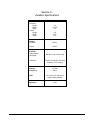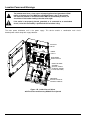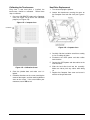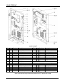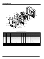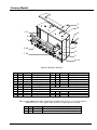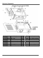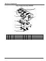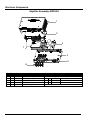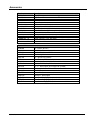
1
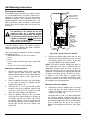
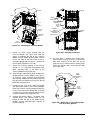
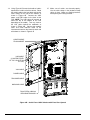
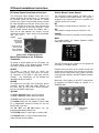
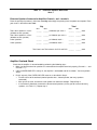
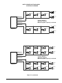
Installation & Owner’s Manual
U.S. and Canada; call toll-free:
Outside the U.S. and Canada; call:
1-877-ROC_N_ROL (1-877-762-6765)
+1 (616) 243-3633
E-Mail: [email protected] Web: www.amietertainment.com
22022617 Rev M
AMI NGX JUKEBOX WARRANTY
AMI extends the original operator of this equipment the following warranty:
All parts are guaranteed to be free of defects in material and workmanship for the specific periods listed. AMI agrees to repair or replace
without charge during such period any part which proves defective upon examination by AMI. All costs of shipping a defective part to AMI’s
offices shall be borne by the original operator. AMI shall bear the shipping costs for the replacement of defective parts.
Component
Electronic Circuit Boards
Core Computer Motherboard
Electrical & Mechanical
LCD Display
Touch Screen Sensor
Touch Screen Controller
Hard Drives
Warranty Period
(from date of shipment)
2 Years
1 Year
2 Years
1 Year
1 Year
1 Year
Life*
Condition
Parts
Parts
Parts
Parts
Parts
Parts
*Full Replacement by AMI, at no charge, for the life
of the AMI Entertainment® contract.
In the case of parts supplied to AMI as components, AMI extends the same warranty period as extended by the original manufacturer.
The above warranty applies provided that all parts of the product have been serviced properly as directed in the service manual, and
provided the alleged defective part, upon examination by AMI, shall prove to be thus defective. Under no circumstances shall AMI be liable
for any incidental, consequential or special damages, losses or expenses arising from or in connection with the use of, or the inability to use,
the product for any purpose. AMI reserves the right to make any changes or improvements in its products without notice and obligation, and
without being required to make corresponding changes or improvements in products theretofore manufactured or sold.
This warranty will not apply to any product or any part which has been subjected to any accident, abuse, or misuse.
AMI ENTERTAINMENT NETWORK, LLC EXTENDS NO WARRANTY, EXPRESSED OR IMPLIED, TO PURCHASERS OR USERS OF
ITS PRODUCTS EXCEPT AS HEREIN SET FORTH, WHETHER BY OPERATION OF LAW OR OTHERWISE.
Table of Contents
Important Safety Instructions ________________________________________ 2
Section A - Jukebox Specifications ___________________________________ 3
Section B - Placing the Wall-Mounted Jukebox on Location _______________ 5
Location Power and Warnings _________________________________________________ 6
Jukebox Power and Reset Switch ______________________________________________ 7
Wall Mounting Instructions ____________________________________________________ 8
IR Remote Installation Instructions ____________________________________________ 11
Testing the Unit ___________________________________________________________ 12
Section C - Sound System Set Up ___________________________________ 13
Extension Speaker Operation ________________________________________________ 14
Selecting Speaker Power____________________________________________________ 14
Selection Procedures____________________________________________________ 14
Extension Speakers Connected to Amplifier Channel + and – terminals ____________ 15
Amplifier Overload Check ___________________________________________________ 15
Section D - Service & Maintenance __________________________________ 19
Recommended Routine Maintenance __________________________________________ 20
Calibrating the Touchscreen _________________________________________________ 21
Hard Drive Replacement ____________________________________________________ 21
Section E - Troubleshooting ________________________________________ 23
LED Indicators ____________________________________________________________ 24
Troubleshooting Charts _____________________________________________________ 26
Connection Diagrams_______________________________________________________ 28
Section F - Parts Catalog___________________________________________ 35
Front Door/LCD Assembly ___________________________________________________ 36
Inside Cabinet ____________________________________________________________ 37
Currency Module __________________________________________________________ 38
Electronic Components _____________________________________________________ 40
Accessories ______________________________________________________________ 43
NGX Jukebox
1
22022617 Rev M
Important Safety Instructions
1. Read these instructions.
9. Protect the power cord from being walked on or
pinched, particularly at plugs, convenience
receptacles, and the point where they exit from
the apparatus.
2. Keep these instructions.
3. Heed all warnings.
10. Only use the attachments/accessories specified
by the manufacturer.
4. Follow all instructions.
5. Do not use this apparatus near water.
11. Use only with the bracket specified by the
manufacturer or sold with the apparatus.
6. Do not block any ventilation openings. Install in
accordance with the manufacturer’s instructions.
12. Unplug this apparatus during lightning storms or
when unused for long periods of time.
7. Do not install near any heat sources such as
radiators, heat registers, stoves, or other
apparatus (including amplifiers) that produce
heat.
13. Refer all servicing to qualified service personnel.
Servicing is required when the apparatus has
been damaged in any way, such as when the
power-supply cord or plug is damaged, liquid has
been spilled or objects have fallen into the
apparatus, the apparatus has been exposed to
rain or moisture, does not operate normally, or
has been dropped.
8. Do not defeat the safety purpose of the polarized
or grounding-type plug. A polarized plug has two
blades with one wider than the other.
A
grounding type plug has two blades and a third
grounding prong. The wide blade or the third
prong is provided for your safety. If the provided
plug does not fit into your outlet, consult an
electrician for replacement of the obsolete outlet.
The lightning flash with arrowhead symbol,
within an equilateral triangle is intended to alert
the user to the presence of uninsulated
“dangerous voltage” within the product’s
enclosure that may be of sufficient magnitude
to constitute a risk of electric shock to persons.
The exclamation point within an equilateral
triangle is intended to alert the user to the
presence of important operating and
maintenance servicing instructions in the
literature accompanying the jukebox.
WARNING
To reduce the risk of fire or electric shock, do not expose this apparatus to rain or
moisture. No objects filled with liquid, such as vases, shall be placed on the apparatus.
AVERTISSEMENT
Pour réduire le risque d'incendie ou un choc électrique, ne pas exposer cet appareil à
la pluie ou à l'humidité. Aucun objet rempli de liquide, comme les vases, ne doit être
placé sur l'appareil.
CAUTION!
RISK OF ELECTRIC SHOCK. DO NOT OPEN
DO NOT REMOVE ANY COVERS, GUARDS, OR SHIELDS.
NO USER SERVICEABLE PARTS ARE INSIDE THIS JUKEBOX.
REFER SERVICING TO QUALIFIED SERVICE PERSONNEL.
ATTENTION!
RISQUE DE CHOC ÉLECTRIQUE. NE PAS OUVRIR
NE JAMAIS RETIRER LES COUVERCLES, GARDES, OU DES BOUCLIERS.
AUCUNE PIÈCE RÉPARABLE DANS CE JUKEBOX.
CONFIER L'ENTRETIEN DE PERSONNEL QUALIFIÉ.
22022617 Rev M
2
NGX Jukebox
Section A Jukebox Specifications
NGX with Currency Module
Dimensions:
Uncrated:
Height
Width
Depth
Crated:
Height
Width
Depth
43”
18.375”
8.5”
59”
22.5”
11.5”
Weight:
Uncrated
102 lbs.
Crated
125 lbs.
Amplifier:
Output Power:
(Standard)
Protection:
500 Wrms into 4 Ohm Load
Thermal and speaker overload
Automatic, self resetting
Voltage:
Frequency:
LCD:
115VAC
60Hz
32” vertical LCD flat screen
1920 x 1080 resolution
Speakers:
NGX Jukebox
none
3
22022617 Rev M
This page is intentionally left blank.
22022617 Rev M
4
NGX Jukebox
Section B Placing the Wall-Mounted Jukebox on Location
• Location Power and Warnings
• Jukebox Power and Reset Switch
• Wall Mounting Instructions
• IR Remote Installation Instructions
• Testing the Unit
NGX Jukebox
5
22022617 Rev M
Location Power and Warnings
!
The jukebox must have a clean source of properly-phased and grounded 115VAC
power at 10 amps max. This MUST be provided 24 hours a day, 7 days a week.
The outlet the jukebox is connected to must NOT be controlled by a switch, nor
should the circuit breaker feeding it be shut off at night.
If the outlet is not properly phased, grounded, or is connected to an overloaded
circuit, it must be corrected by a qualified electrician before using.
The main power distribution unit is the power supply. This device contains a combination main circuit
breaker/power switch along with surge protection.
ATX RESET
SWITCH
POWER
SUPPLY
MAIN POWER
ON/OFF SWITCH
COMPUTER CORE
ASSEMBLY
(SERVICE, REJECT,
CALIBRATE, POWER
BUTTON LOCATION)
ADDITIONAL
SERVICE BUTTON IN
CURRENCY MODULE
Figure 1-B – Inside View of Cabinet
with Front Door and Currency Module Door Opened
22022617 Rev M
6
NGX Jukebox
Jukebox Power and Reset Switch
Hard Power Down
The NGX jukebox is powered from a standard
115VAC wall plug using the provided power cord.
Inside the jukebox, power is routed to a power
distribution assembly located on the left-hand side of
the cabinet (see Figure 1-B). This assembly includes
a combination 15A circuit breaker/power ON/OFF
switch. All other components in the jukebox are
powered by plugging them into this power distribution
assembly.
When the jukebox power cord is unplugged or the
main power ON/OFF switch is turned off (see Figure
1-B), the jukebox is in the hard power down state. All
power is removed from all components in the
jukebox.
ATX Reset Switch
There is a hidden ATX reset switch located inside the
cabinet on the upper-left side just below the cooling
fan (see Figure 1-B). It is accessible by either
opening the jukebox door, or by inserting a paper
clip, toothpick, or other long, thin object through the
access hole on the left side of the jukebox.
Soft Power Down
The Core Computer and other components in the
jukebox should remain powered up at all times.
However, there may be times when the jukebox
needs to be turned off so that customers cannot
insert money or make selections. The soft power
down mode will give every outward appearance that
the jukebox is off by turning off the lights, the LCD
display, the bill acceptor(s), and the credit card
reader; however, the Core Computer and other
internal components remain powered up. There are
multiple ways to enter and exit this soft power down
mode:
•
Core Computer Power Button – The button
labeled “POWER” on the Core Computer
inside the jukebox (see Figure 1-B) is used to
enter the soft power down mode. Push it
again to exit the soft power down mode.
•
IR Remote Control – The button labeled
“POWER” on the IR remote control
transmitter will also toggle the soft power
state just like the button described above.
•
6 Button Wired Volume Control – This
control can be modified to provide a POWER
function. See Wired 6 Button Volume Control
on page 11 for details.
•
The ATX Reset Switch resets the Computer
Core. This is like the reset switch on a PC.
Pressing and releasing this switch will cause
the computer main board to completely
reboot. Use this switch only if the jukebox is
completely non-responsive. Additionally,
when the Computer Core has been powered
down using the “Shutdown Jukebox” option
in Service Mode, pushing this button will
restart the computer.
Computer Core
The jukebox Computer Core can be powered off by
pressing the “SERVICE” button on the Computer
Core (see Figure 1-B), and then touching “Shutdown
Jukebox” on the touchscreen. This will turn off the
Computer Core and other components that get their
power from the ATX power supply in the Computer
Core. To restore power after turning off the ATX
power supply, the jukebox must be rebooted. Reboot
the jukebox by toggling off the main power ON/OFF
switch (see Figure 1-B) and then toggling it back on,
or by pushing the ATX Reset Switch (see “ATX Reset
Switch”).
NGX Jukebox
7
22022617 Rev M
Wall Mounting Instructions
Choosing the Location
WALL
STUD
The jukebox must be mounted on a strong, flat wall.
It is recommended that a sub panel made from ¾”
plywood or similar material be used and properly
shimmed to provide a flat mounting surface. The
jukebox should be visible and convenient to use. Do
NOT install directly above a radiator or other source
of heat. Be sure the speaker wires can be easily run
to the unit.
UPPER KEYHOLES
(SHOULD BE 81.5"
FROM THE FLOOR)
MOUNTING
HOLES
WARNING
The mounting of the jukebox on the wall
should be done by a qualified installer
familiar with wall construction and loading.
The wall and installation hardware MUST be
capable of supporting a 700 lb. load for the
NGX. Failure to follow these instructions
could result in serious injury.
FOR
MOUNTING
JUKEBOX
DIRECTLY
TO STUD
WALL, AMI
RECOMMENDS
A THIRD
LAG
SCREW
INTO STUD
The NGX jukebox cabinet and jukebox Currency
Module are packed separately with both assemblies
contained in one shipping carton.
LOWER
KEYHOLES
Tools and hardware required for normal installation
into wood wall studs:
• Socket wrench with 3/8” and 7/16” sockets
• Level
• Pencil
• Punch or awl (to start the lag screws) and/or drill
driver
• (4) 1/4” x 1-1/2” lag screws provided
Figure 2-B – Inside View of the Cabinet
5.
NOTE: If the wall is concrete, cinder block, brick, or
uses metal wall studs, then a subpanel with the
appropriate fasteners must be used. At least 4”
heavy duty fasteners (one in each corner) must be
employed. The fasteners and subpanel must be able
to support a minimum 200 lbs. Do NOT use “pressin” anchors or any other “light” or “medium” duty
fasteners. Consult a contractor experienced in the
type of construction used if there is any doubt about
the strength of the mounting devices.
Mounting the Jukebox Cabinet
1.
Remove the jukebox cabinet from its packing
carton. Open the door, ensure all cables are
detached from the door, and then lift the door off
of the cabinet. Set the door aside for the
moment.
2.
Install a subpanel or locate a wall stud roughly
in the center of where the jukebox will be
mounted. See Figure 2-B.
3.
Install the first ¼” x 1½” lag screw 80” up from
the floor. If not using a subpanel, center the lag
screw on a wall stud. This should be on the
center line of the jukebox. See Figure 2-B.
4.
Hang the jukebox cabinet on this lag screw
using one of the upper keyholes in the back of
the jukebox cabinet (see Figure 2-B). Ensure
the jukebox cabinet is level and mark the wall
for the lower keyhole and the mounting holes in
the top right and top left of the cabinet (See
Figure 2-B).
22022617 Rev M
Remove the jukebox cabinet from the wall, drill
pilot holes for the remaining lag screws, re-hang
the jukebox cabinet and secure it to the wall
using the additional lag screws provided.
Mounting the Currency Module
6.
Remove the Currency Module from its packing
carton and open the door. Remove the coin
bucket and remove the bill box from the bill
acceptor (see Figure 3-B).
Locate the two 1/4” x 20 x 1/2” bolts packed with
the Currency Module. Position and hold the
Currency Module directly below the jukebox and
start threading both bolts from the inside bottom
of the jukebox into the top of the Currency
Module. Do not tighten the bolts yet. See Figure
3-B.
8
NGX Jukebox
CABINET
CABINET
DOOR
DOOR
COMPUTER
CORE
1/4" X
1/2"
BOLTS
BLOCKOUT
PLATE
(RIGHT
SIDE)
CURRENCY
MODULE
(SOME PARTS
REMOVED
FOR CLARITY)
SPACER
/ RAMP
CURRENCY
MODULE
COIN
BUCKET
GROUND
WIRE
BILL
BOX
Figure 3-B – Mounting the Currency Module
8.
9.
Locate the black spacer packed with the
Currency Module (see Figure 3-B). Slide the
spacer in between the top of the Currency
Module and the bottom of the jukebox cabinet.
Ensure the ramp at the front of the spacer is
oriented properly and the spacer is pushed all
the way back. Tighten the 1/4” bolts.
Figure 4-B – Hanging the jukebox
13. The front door is secured using slide hinges,
which require no tools to attach. To attach the
front door, carefully lift the door, line up the
hinge pins on the cabinet with the mating hinge
barrels on the front door, and lower the door
(see Figure 5-B).
Secure the Currency Module to the wall by
driving a ¼” x 1½” lag screw through one of the
lower mounting holes in the back of the
Currency Module and into the wall.
10. Open the right side block-out plates between the
jukebox and the Currency Module (see Figure 4B). Feed the 12-pin connector and cable from
the Currency Module into the jukebox and plug
the cable into the jukebox main harness directly
below the Computer Core.
HINGE
BARREL
ON FRONT
DOOR
11. Locate the free ends of the credit card reader
and ground wire cables in the Currency Module.
Route these cables into the jukebox through the
access hole. Connect the ground wire as shown
in Figure 4-B. Connect the USB cable from the
credit card reader to the Computer Core.
12. Prepare the external wiring. The power cord,
speaker wiring, and Ethernet cable can be
routed to enter the top or the bottom of the
jukebox. Use the block-out plates and nuts to
secure the wiring.
NGX Jukebox
HINGE
PIN ON
CABINET
Figure 5-B – Detail View of Top Cabinet Hinge
with Front Door Opened
9
22022617 Rev M
14. Using Figure 6-B, locate the bundle of cables
taped to the inside back of the cabinet. Route
the cable bundle to the front door and into the
cable clamps to the right of the monitor as
shown in Figure 6-B. Connect the VGA,
power, and USB cables to the back of the
LCD (NOTE: The USB cable will connect to
either the top or the bottom of the LCD
depending on the model). Tuck any slack on
the LCD cables behind the metalwork as
shown in Figure 6-B. Connect the modular
cable and small two-wire cable to the
interconnect board on the lower-left back side
of the door as shown in Figure 6-B.
15. Make sure all cables are dressed properly.
Use the cable clamps in the jukebox to keep
cables in place. Make sure nothing interferes
with opening and closing the door.
CABLE BUNDLE
FROM CABINET
USB CABLE
(LOCATED EITHER
AT TOP OR BOTTOM
OF LCD)
VGA CABLE
POWER CABLE
TWO-WIRE CABLE
MODULAR CABLE
TUCK EXTRA CABLING
BEHIND METALWORK
Figure 6-B – Inside View of NGX Jukebox with Front Door Opened
22022617 Rev M
10
NGX Jukebox
IR Remote Installation Instructions
IR Remote Control Installation Instructions
Wired 6 Button Volume Control
The Continental Video Jukebox comes with an IR
remote (located in the Handy Pack). To install, plug
the provided cable into the provided IR remote
receiver (see Figure 10-B) and route the other end of
the cable through one of the wire access holes in the
cabinet. Connect the end of the cable into the port
labeled “IR Receiver” on the Core Computer. Install
the IR remote receiver above the jukebox, with a
clear line of sight between the receiver and the
handheld transmitter. Plug in and turn on the jukebox
and test the
remote.
The Continental Video Jukebox also comes with a
small 6 button wired remote control. This control is
designed to be mounted close to the jukebox and
provides some basic functions.
INT.
These buttons change volume for Channels 1 & 2.
EXT.
These buttons change volume for Channels 3 & 4.
CANCEL
This button will cancel the selection currently playing.
MUTE
This button toggles the jukebox between PAUSE
mode and PLAY mode.
CABLE
CONNECTED
TO TOP OF
RECEIVER
RECEIVER MUST
BE INSTALLED
WITH SENSORS
FACING FRONT
Figure 10-B – IR Remote Receiver
Button Functionality on the IR Remote
Transmitter
To enable or disable options on the IR remote, see
“IR Remote Setup” in the Network Setup, Jukebox
Operation, Operator Setup Screens Manual.
The MUTE button on this remote can be repurposed
to function as a POWER button.
REJECT
This button is used to cancel (or “reject”) the
selection currently playing, and cancels all (rejects
all) selections in the queue if held down for four
seconds. This functionality can be enabled and
disabled through the software.
Remove the back cover of the remote control then
remove the circuit board. There are two shut jumpers
located on the board. When these jumpers are both
in the right hand position, the MUTE button functions
as MUTE.
Move both shunt jumpers to the LEFT hand position
to repurpose the MUTE button to function as a
POWER button.
POWER
This button turns the lights, the LCD display, the bill
acceptors, and the credit card reader ON/OFF. To
turn them back on and resume normal operation,
press the “POWER” button again.
VOLUME
The CH1+ and CH2+ buttons raise the volume.
The CH1– and CH2– buttons lower the volume.
The PLAY button puts the jukebox in play mode.
The PAUSE button puts the jukebox in pause mode
for a programmed amount of minutes or until the
PLAY button is pushed.
The AP OFF and AP ON buttons turn any
programmed Autoplay mode on/off.
The FUTURE button is used to give a remote credit.
The VID SEL button is used to enable and disable
video selections on the jukebox.
NGX Jukebox
11
22022617 Rev M
Testing the Unit
Initial Set Up
5. To test the coin acceptor, deposit U.S. quarters
into the coin slot and verify proper credit is
awarded.
6. To test the credit card reader, swipe a valid credit
card and check that the screen displays the last
four digits of the credit card.
7. When finished, touch the Back button to return to
the Main Menu.
When all of the network connections have been
made, boot up the jukebox. The first time you turn on
the jukebox with a new hard drive, you will see the
Local Music Configuration Screen, which lists the
available local music configurations that can be
installed on the jukebox. You will be prompted to
select one of the available lists. This selection can
be changed at any time by pressing the SERVICE
button on the Computer Core, and then touching
System Setup -> Advanced Administration ->
Local Music Configuration.
Touch the View button to display a dialog box listing
all of the albums in the selected list. Some albums
may appear grayed out; this means that some or all
of the songs in the album are not currently stored on
this jukebox. If a list with grayed albums is installed,
the grayed albums will start being downloaded to the
jukebox within 24 hours (as long as the jukebox is
connected). If the jukebox becomes disconnected,
any songs not yet downloaded will be unavailable to
patrons.
Touch the Install button to display a dialog box
prompting you to install the selected list. To install
the selected list, touch the Install button at the bottom
of the dialog box.
Testing the Network
Enter Service Mode by pressing and releasing the
“SERVICE” button on the Computer Core. To test
the network:
1. Touch the System Setup button on screen and
then touch Advanced Administration.
2. On the Advanced Administration Screen, touch
Configure Server. Then touch the Test
Connection button. This test confirms the
jukebox can connect to AMI’s server (“Server
Found”), and authenticate a connection with
AMI’s server (“Connected”).
3. If the connection is successful, you will see “Yes”
next to “Server Found” and “Connected”. If the
connection fails, you will see “No”. If the
connection fails, check the settings on the
Network Information Screen (Diagnostics –>
Network Information). This screen will allow
you to check the IP Configuration and run LAN
and WAN tests.
Testing the Touchscreen, Bill and Coin
Acceptor(s), and Credit Card Reader
Touchscreen – Every time a new hard drive is
installed, the touchscreen should be calibrated.
Testing the Audio
NOTE: For operators pre-testing the jukebox in their
own facility, any features in the application
associated with the network will not work unless the
jukebox is connected to the Internet.
1. If the jukebox is not in Service Mode, press the
“SERVICE” button on the Computer Core to enter
Service Mode.
2. Add one (or more) credits to play a song and test
the audio. Touch Cash Management and then
touch Credit Management.
3. Touch the box under “Credits” and a pop-up box
will display.
4. Touch Clear to remove the “0” from the box.
5. Touch 1 (or more) and then touch Update.
6. Touch Save on the Credit Management Screen.
7. Touch Exit Service Mode.
8. After connecting speakers to the jukebox (see
section C), play a local music selection to test the
audio.
Follow these steps to calibrate.
1. Press the “CALIBRATE” button on the Computer
Core (see Figure 1-B) to launch the calibration
program.
2. Close the jukebox door and make sure it is
locked.
3. Follow the directions on the screen, touching the
center of the targets, and then touching different
areas on the screen. If the cursor follows your
movement, touch YES to exit.
Bill/Coin Acceptor(s) and Credit Card Reader –
(NOTE: Credit Card functionality requires a
broadband Internet connection).
1. Press the “SERVICE” button on the Computer
Core to enter Service Mode.
2. Touch the Diagnostics button.
3. Touch Credit Device Tests.
4. To test the bill acceptor(s), insert a $1, $5, $10,
and $20 bill (into each bill acceptor, if the jukebox
has two) and check the screen to make sure
proper credit is awarded.
22022617 Rev M
12
NGX Jukebox
Section C Sound System Set Up
• Extension Speaker Operation
• Selecting Speaker Power
• Speaker Connection Diagrams
NGX Jukebox
13
22022617 Rev M
Sound System Set Up
The NGX jukebox sound system is powered by an ICEpower 250ASX2 Class 2 power amplifier manufactured by
Bang & Olufsen. Speaker terminals are provided to connect extension speakers directly to the amplifier. An Audio
Output Transformer Kit (part number 22180806) is available if your installation uses 70 volt speakers or you need to
connect extension speakers using various power taps.
Extension Speaker Operation
To avoid poor sound quality, care must be taken when adding extension speakers. The following requirements
must be met:
•
Speakers connected to the amplifier must be wired so the power consumed by the extension speakers
does not exceed the amplifier power rating of 250 watts per channel.
•
Complete the Extension Speaker Worksheet (Table 1-1) for each channel and verify it does not exceed
the 250 watt amplifier channel rating. After wiring the speakers, perform the Amplifier Overload Check
immediately following Table 1-1.
•
All speakers must be connected with the correct polarity (see Figure 1-A).
•
Do not bridge output channels.
Low Impedance Speakers
Low impedance speakers (16, 8, or 4-ohm) can be used when the connecting cable is less than 100 feet. Keep
the following two things in mind when wiring your speakers:
1. No more than one 4-ohm speaker should be connected to a speaker line. If several 4-ohm speakers are to
be used, each speaker should have its own line.
2. The loss in 100 feet of 18-gauge zip-cord feeding on an 8-ohm speaker is 15%. The loss for two 8-ohm
speakers is 30%.
Selecting Speaker Power
General Instructions
This section will lead you through the power and speaker selection process. This process consists of three
major steps and several smaller steps. The major steps are:
1. Identify the extension speakers and compute the speaker power for speakers connected directly across the
amplifier.
2. Make the extension speaker connections.
3. Perform an amplifier overload check (see instructions immediately following Table 1-1).
Selection Procedures
•
Use a pencil (you may want to revise your figures) to fill in the Extension Speaker Worksheet on the
following pages.
•
Use the Table 1-1 Worksheet to help you calculate the amount of power consumed by the extension
speakers.
An extension speaker RMS power rating should be at least 10% higher than the power it will consume at
maximum jukebox volume.
•
When RMS power to speaker
at maximum jukebox volume is:
Then recommended RMS power
rating of speaker is:
240 watts
120 watts
60 watts
30 watts
300 watts
150 watts
75 watts
40 watts
22022617 Rev M
14
NGX Jukebox
Table 1-1 – Extension Speaker Worksheet
Sheet 1
Extension Speakers Connected to Amplifier Channel + and – terminals
Place the quantity of speakers in the blank under Qty and multiply the quantity times the power consumption. Place
your results in the blank under Total.
Qty
CH 1
Two 8-ohm speakers in series:
(30 watts to each speaker)
Two 4-ohm speakers in series:
(60 watts to each speaker)
8-ohm speakers:
4-ohm speakers:
Total
CH 2
CH 1
CH 2
______
______ at 60 watts per series =
______
______ watts
______
______ at 120 watts per series =
______
______ watts
______
______
______ at 120 watts each =
______ at 240 watts each =
______
______
______ watts
______ watts
______
______ watts
Total Load, sum Total columns for CH1 and CH2
Amplifier Overload Check
Check that the amplifier is not overloaded by performing the following steps:
1. Make sure that the extension speakers are connected to the amplifier terminals properly (Channel1 + – and
Channel 2 + –).
2. If the red OVERLOAD LED is always lit, the amplifier is overloaded and will shut down. You must perform
Step 3.
3. Do this step only if the OVERLOAD LED came on as described in Step 2.
•
Find the source of the overload (shorted speaker wires, shorted speaker, too many speakers
connected).
•
After you fix the short, disconnect a few speakers to reduce the wattage. Repeat Step 2.
•
If no overload is detected, reconnect the disconnected speakers (ensure you do not have too many
speakers, use Table 1-1). Repeat step 2.
NGX Jukebox
15
22022617 Rev M
NOTE: SPEAKER WATTAGE SHOWN
IS RATING OF SPEAKER
Channel 1 +
+
8 Ohms
+
150 W
8 Ohms
150 W
Channel 1 Load as shown is
240 W per channel.
Maximum pow er capacity is achieved.
Channel 2 +
Channel 2 -
+
8 Ohms
+
150 W
8 Ohms
150 W
Amplifier
+
+
8 Ohms
150 W
Channel 1 +
8 Ohms
50 W
+
8 Ohms
50 W
Channel 1 -
Load as shown is
180 W per channel
Channel 2 +
+
Channel 2 -
+
Amplifier
50 W
8 Ohms
150 W
8 Ohms
+
8 Ohms
50 W
+
+
8 Ohms
150 W
Channel 1 +
4 Ohms
75 W
+
4 Ohms
75 W
Channel 1 Load as show n is
240 W per channel.
Maximum power capacity is achieved.
Channel 2 +
+
Channel 2 -
+
Amplifier
8 Ohms
150 W
4 Ohms
75 W
+
4 Ohms
75 W
Figure 1-C
22022617 Rev M
16
NGX Jukebox
NOTE: SPEAKER WATTAGE SHOWN
IS RATING OF SPEAKER
+
+
16 Ohms
+
75 W
16 Ohms
+
75 W
Channel 1 +
+
8 Ohms
50 W
Channel 1 -
Load as shown is
240 W per channel.
Maximum power capacity is achieved.
Channel 2 +
Channel 2 -
+
+
Amplifier
50 W
16 Ohms
75 W
8 Ohms
16 Ohms
+
75 W
16 Ohms
+
75 W
50 W
16 Ohms
75 W
8 Ohms
+
8 Ohms
50 W
+
8 Ohms
+
50 W
Channel 1 +
+
8 Ohms
8 Ohms
+
50 W
+
50 W
8 Ohms
8 Ohms
+
50 W
+
50 W
8 Ohms
8 Ohms
50 W
+
50 W
8 Ohms
50 W
Channel 1 Load as shown is
240 W per channel.
Maximum power capacity is achieved.
Channel 2 +
Channel 2 -
+
Amplifier
8 Ohms
+
50 W
+
8 Ohms
50 W
8 Ohms
+
50 W
+
8 Ohms
50 W
8 Ohms
+
50 W
+
8 Ohms
50 W
8 Ohms
50 W
+
8 Ohms
50 W
Figure 1-C (continued)
NGX Jukebox
17
22022617 Rev M
This page is intentionally left blank.
22022617 Rev M
18
NGX Jukebox
Section D Service & Maintenance
• Recommended Routine Maintenance
NGX Jukebox
19
22022617 Rev M
Recommended Routine Maintenance
Heat is the biggest enemy of electronic
components. Proper maintenance is essential for
maximum earnings and reliability.
It is very important to keep all cooling fans clean.
Once dust and dirt is visible on a cooling fan, the
airflow is reduced by at least 25%. There are several
cooling fans in the cabinet (see Figure 1-D).
2. To remove the bill stacker, slide the tab on the
back of the bill acceptor towards the front door
and push the stacker forward and then upward.
3. Open the side door on the bill stacker to
remove the cash.
4. Slide the bill stacker back on the bill acceptor.
Be sure the green light is on (for MEI, make
sure the green lights/arrows are flashing).
5. Close and lock the Currency Module door.
Recommended preventative maintenance
The NGX is designed such that all routine service
can be performed by opening the Currency Module
door only. The Currency Module is where you will find
all the money deposited into the jukebox. There is
also a SERVICE push button which will allow access
to the Service Mode without having to open the main
jukebox door.
Minor Service
Perform these steps a minimum of every 3 months if
operating where smoking is allowed, or operating in a
dusty environment. Perform these steps a minimum
of every 6 months if operating in a very clean
environment. You will need a new, soft 2”
paintbrush*.
1. Gently brush* dirt from the cabinet cooling
fan. Verify fan operation.
2. Check the operation of the CPU fan from the
“Health Status” Screen.
3. Listen to the CPU fan for excessive noise or
vibration.
4. Clean the bill acceptor with an approved
cleaning card.
5. Clean the credit card reader with an
approved cleaning card.
6. Clean and calibrate the touchscreen (see the
next page for calibration instructions).
Routine Service
The following steps take about 3 minutes and should
be performed at each collection.
1. Check the CPU fan from the “Health Status”
Screen.
2. The chassis fan in the core computer may not
be spinning. This is normal if the fan has a 4
wire plug and the temperature is not too high.
The fan will briefly spin up during boot up and
spin continuously when the temperature in the
core computer gets too warm,.
3. Ensure the cabinet fan on the upper-left side of
the cabinet is blowing air out and the fan looks
clean. See Figure 1-D.
4. Be sure that nothing is resting on top of the unit
or otherwise blocking the airflow around the
machine.
Cleaning the Touchscreen
Any standard glass cleaner can be used to clean the
touchscreen. Always spray the glass cleaner on the
cloth or towel and not directly on the touchscreen.
Glass cleaner sprayed directly on the screen could
possibly leak inside and cause damage.
Cleaning the Currency Door Panel
The door panel is made of polycarbonate. We
recommend cleaning with a mild cleaner and a soft
cloth to avoid scratching the surface.
Annual Service
The following steps should be performed every year
in addition to everything in the minor service section.
1. Vacuum the interior of the cabinet and fans.
2. Inspect the power cord for fraying or damage.
3. Check the power ground.
4. Check all LAN connections and wiring.
5. Listen to all speakers to make sure they are
operating correctly.
Figure 1-D – Inside View of Cabinet
Collecting from the Bill Acceptor
1. Unlock and open the front door of the Currency
Module (lower key lock). The front door will
swing down. There is a fall-stop cable to keep
the door from opening too far.
22022617 Rev M
Scheduled maintenance always costs less time
and money than an unscheduled breakdown.
20
NGX Jukebox
Calibrating the Touchscreen
Hard Drive Replacement
Every time a new hard drive is installed, the
touchscreen should be calibrated. Follow these
steps to calibrate.
1. Turn off and unplug the jukebox.
2. Loosen the thumbscrew securing the cover on
the Computer Core and slide it off (see Figure 4D).
1. Press the “CALIBRATE” button on the Computer
Core (see Figure 2-D) to launch the calibration
program (see Figure 3-D).
Figure 2-D – Computer Core
CALIBRATE
Figure 4-D – Computer Core
3. Carefully slide the hard drive out of the assembly
as far as cabling will allow.
4. Disconnect the SATA power and data cables
from the drive.
5. Connect the SATA power and data cables to the
new hard drive.
6. Slide the hard drive back into the assembly.
Make sure not to pinch any cables while doing
so.
Figure 3-D – Calibration Screen
2. Close the jukebox door and make sure it is
locked.
7. Replace the Computer Core cover and secure it
with the existing thumbscrew.
3. Follow the directions on the screen, touching the
center of the targets, and then touching different
areas on the screen. If the cursor follows your
movement, touch YES to exit.
NGX Jukebox
21
22022617 Rev M
This page is intentionally left blank.
22022617 Rev M
22
NGX Jukebox
Section E Troubleshooting
• LED Indicators
• Troubleshooting Chart
• Connection Diagrams
NGX Jukebox
23
22022617 Rev M
LED Indicators
The LEDs are described below to help you isolate a problem.
COMPUTER CORE ASSEMBLY (61197004)
USB Tx LED – It should be flashing, indicating good communication between the motherboard and the I/O
board.
USB Rx LED – It should be flashing, indicating good communication between the motherboard and the I/O
board.
STATUS LED – Flashes three times on power up, but otherwise it should be off.
RS485 Tx LED – It should be flashing, indicating good communication between the I/O board and Rowelink
devices such as the Amplifier and Volume Control Units.
RS485 Rx LED – It should be flashing, indicating good communication between the I/O board and Rowelink
devices such as the Amplifier and Volume Control Units.
IR RECEIVER LED – Flashes when an IR signal is received.
+5VDC – Indicates this voltage from the ATX power supply is present.
+12VDC – Indicates this voltage from the ATX power supply is present.
HDD LED (RED) – Flashes when the motherboard is accessing data on the hard drive.
PWR LED (GREEN) – When lit, indicates the power supply in the Computer Core assembly is on.
AMPLIFIER ASSEMBLY (40991404)
POWER (Green) – When lit, indicates power is applied to the Amplifier.
STATUS (Red) – Indicates the status of the Preamplifier/Amplifier.
COM (Green) – Quick flashes indicate communication with the Core Computer is OK.
MUTE (Red) – Indicates the mute status of the Amplifier (On = muted, Off = not muted)
OVERCURRENT – When lit, indicates the Amplifier is overloaded. Verify speaker load and ensure there are
no shorted speaker wires.
THERMAL – When lit, indicates the Amplifier is overheating. Be sure the cabinet fan(s) are working, the
filters are clean, and nothing is blocking air flow through the cabinet.
22022617 Rev M
24
NGX Jukebox
Preamplifier STATUS – normal operation
The STATUS LED is used to indicate the status of the preamplifier. Under normal conditions the STATUS LED will
flash once on power up, stay off for a second, and then turn back on and stay on. If either of the two microphone
inputs become active, either by activation of the SENSE line or by the Voice Activation Circuits, the STATUS LED
will blink on and off at a 150ms rate until the microphone circuits become inactive.
Preamplifier STATUS – error conditions
The STATUS LED is used to indicate possible faults on the preamplifier board. During power up the preamplifier
runs a self test. If a fault is detected, the STATUS LED is used to indicate what may be wrong. The LED will repeat
a pattern of a specific number of blinks.
The blink pattern is 500ms on, 500ms off and then one to seven quick 100ms on blinks, three seconds off. The
blinking pattern will repeat until the preamplifier is reset or power is turned off.
Number of Blinks
1
2
3
4
5
6
7
Problem Description
Digital Audio Processor did not come out of RESET
Digital Audio Processor COM error
EEPROM COM error
Digital Audio Processor memory load error
EEPROM data error
Digital Potentiometer COM error in Mic circuit
2
I C SDA line is stuck low
If the DAP fails during normal operation, after power up the STATUS led will start to blink one second on, two
seconds off, continuously until power is cycled or until the DAP failure goes away.
NGX Jukebox
25
22022617 Rev M
Troubleshooting Charts
The best way to isolate a problem is to determine its cause. The following charts should help to narrow down which
module is failing and whether it can be fixed or it needs to be replaced.
Start with finding the “Problem” column that relates the closest to the problem you are experiencing and then match
it to the closest “Symptom”. There can be many “Probable Causes” listed for each Symptom. The Probable
Causes are listed in decreasing order of probability.
PROBLEM
The Windows
operating
system does
not boot up.
SYMPTOM
At the first boot up screen,
“PASSWORD”
The boot up process stops at
“DISK BOOT FAILURE,
INSERT SYSTEM DISK AND
PRESS ENTER.”
The LCD
screen stays
dark when the
jukebox is
powered up.
The PWR LED on the
Computer Core does not light.
The LEDs on the Computer
Core come on, but the screen
stays dark.
PROBABLE CAUSE
1. There is no hard drive in the Computer Core.
2. The plugs are not completely seated in the hard drive.
3. The data cable or power cable has come loose from the
motherboard or hard drive.
1. There is no hard drive in the Computer Core.
2. The data cable or power cable has come loose from the
motherboard or hard drive.
3. The hard drive is faulty.
1. The plug is not completely inserted into the outlet.
2. The wall circuit is not “hot”.
3. The ON/OFF switch on the power supply is in the OFF
position or the circuit breaker has tripped.
4. The ATX power supply in the Computer Core is faulty.
1. The power plug to the display is not seated completely.
2. The harness plug to JUKEBOX I/O on the core computer is
not plugged in.
3. The power distribution assembly is defective.
4. The LCD is faulty.
The LCD
briefly shows
“NO CABLE”
or “NO VIDEO
SIGNAL”.
The
touchscreen
does not work.
The computer is on and all
system’s LEDs and lights are
normal.
1. The video cable wiring is not seated completely.
2. The LCD is defective.
3. The Computer Core is defective.
The application boots up, but
the touchscreen does not
respond to touch.
The
touchscreen
will not
calibrate.
Nothing happens after
pressing the calibration
button.
The calibration program runs,
but will not respond to touch.
1. The USB cable is not seated completely at the LCD or at the
Computer Core.
2. The touchscreen is not calibrated.
3 The touchscreen is defective.
1. The I/O interface board in the Computer Core is faulty.
2. The hard drive is faulty.
3. The Computer Core is faulty.
1. The USB cable plug is not plugged in at the LCD or at the
Computer Core.
2. The touchscreen controller is faulty.
3. The touchscreen sensor (glass) is faulty.
No music from
jukebox.
No sound from jukebox,
although the application
reports “Now Playing…a
Song.”
No sound from the jukebox
and the application doesn’t
appear to be playing the song
selected.
22022617 Rev M
1. Volume control is turned all the way down.
2. The audio mode input routing or muting is configured
incorrectly.
3. Audio cables are disconnected or loose from the Computer
Core or the preamplifier.
4. Volume control is broken.
5. The amplifier is overloaded and shutdown.
1. There are no more credits available for play.
2. Reject song was activated.
26
NGX Jukebox
PROBLEM
SYMPTOM
PROBABLE CAUSE
Machine is
locked up
during
normal
runtime.
Bill acceptor is taking money
but credits are not
accumulating, the
touchscreen is not
responsive, and I/O board
LEDs are not flashing.
The Computer Core is locked up. Reboot it by pressing and
releasing the ATX Reset Switch. If the Computer Core does not
boot up, perform a complete Power Down and Power Up.
The bill
acceptor
does not
work.
Lights on the bill acceptor are
lit, but the bill acceptor will
not accept a bill.
1.
2.
3.
4.
5.
1.
2.
The lights on the bill acceptor
are not flashing.
The bill acceptor bill box is full.
The bill box was not re-installed on the bill acceptor correctly.
There is a jammed bill in the device.
The plugs are not inserted securely at the acceptor.
The bill acceptor is defective.
The cable is damaged at the acceptor.
The jukebox has disabled the bill acceptor. Put the jukebox
into normal operating mode.
The bill acceptor is defective.
The inside wiring installation appointment was not scheduled.
The inside wiring installation has not occurred.
The line was not installed in the pre-selected location.
The line (jack) was not labeled by the technician.
Location
network line
not installed
in the
location.
There is no designated
broadband line installed in
the location.
3
1.
2.
3.
4.
Router does
not work.
When the power supply is
connected to the router,
nothing happens.
1. The AC power plug is not fully inserted in the receptacle on
the back of the router.
2. Router reset circuit in power distribution assembly is defective.
The “Link/Act #” light (on the
front of the router) does not
light up when an Ethernet
cable is plugged in the
respective port.
The WAN light does not light
up.
1. The cable is loose at the Computer Core or router.
2. The jukebox is not powered on.
3. The Ethernet port is defective.
The feature has never
worked in the location before.
1. There is no Ethernet cable connection between the router and
the jukebox.
2. The Ethernet cable is not fully seated in the port on the
Computer Core or in the back of the router.
3. The connection is loose between the installed line and the
router.
4. The cable is bad.
5. The Internet line is down.
6. The hard drive trigger code was not entered.
7. The jukebox has not been added to your contract.
1. The connection has become loose between the router and the
jukebox.
2. The connection has become loose between the installed line
(jack) and the router.
3. All the lights on the front of the router are ON.
4. The router was shut off or lost power.
5. The Internet service provider (ISP) is down.
6. The AMI Entertainment server is down.
The “Music
On
Demand”
feature does
not work.
The feature did work at one
time, but is no longer
available.
NGX Jukebox
1. The broadband connection is not plugged into the WAN port.
2. The cable modem or DSL modem is not powered on.
27
22022617 Rev M
Connection Diagrams
ATX RESET
VGA
28295705 Video Card
PCIe x 16 Slot
DVI
1
2
P1
P2
34052405
Power
HDD
1
2
3
4
5
6
7
8
9
10
22132270
1
2
3
4
5
6
7
8
9
10
+V HDD LED
+V PWR LED
HDD SIGNAL
PWR SIGNAL
GROUND
PWR BTN SIGNAL
RST SIGNAL
RST SW GND
NC
KEY
HDMI
-- OR -56K PCI MODEM
DATA
GND
TX+
TXGND
RXRX+
GND
POWER
+12 V 1
GND
+5 V
GND 12
2.5" SATA
HARD DRIVE
22132252
Y
B
R
B
1
2
3
4
GROUND
POWER
SENSE
PWM
AUDIO
MOTHER BOARD
VCC
DD+
GND
1
2
3
4
USB
-
To Router
To Pream plifier
Main Stereo IN
MOTHER BOARD EMB-B75B
CPU 2.4GHz DUAL CELERON
VCC 1
HEATSINK FAN ASSY
D- 2
RAM 2GB
USB D+
3
1 GND
GND 4
2 TX+
DCD 1
3 TXRXD
2
TXD
3
4 GND PORT 0
5 RX- (WHITE)
4
VCC 1
DTR
6 RX+
GND 5
D- 2
7 GND
DSR 6
D+ 3
7
RTS
GND 4
SATA DATA
CTS
8
COM1 RI 9
USB
1 GND
TOU C H SC R EEN C ONTR OL
2 TX+
C OM1 SER IAL OR USB
3 TX4 GND PORT 1
5 RX- (BLUE)
6 RX+
7 GND
1
2
3
4
1
2
3
4
5
6
7
8
9
10
11
12
13
14
15
16
17
18
19
20
+3.3 V
+3.3 V
GND
+5 V
GND
+5 V
GND
PW-OK
5VSB
+12 V
+3.3 V
-12 V
GND
PS-ON
GND
GND
GND
-5 V
+5 V
+5 V
To Touch
Screen
USB or Serial
To Video
Dis play
LVDS DAT A
GND
GND
+12 V
+12 V
ATX POWER
To Credit
Card Reader
VGA
CPU POWER
120 VAC INPUT
1
2
3
4
5
6
7
8
RING - R
GND
OUT TIP - L
GND
SATA DATA
40952205
ATX POWER
SUPPLY
TX+
TXRX+
----RX-----
EMB-B75B
40924214
40922609
30800443
34039506
70036633
1
2
3
4
5
6
7
1
2
ETHERNET
SYSTEM FAN
FAN
34039108
RING
TIP
LVDS INV
22132250
VCCa 1
VCCb 2
-DATAa 3
USB (2) -DATAb 4
PORTb = USB MODEM
+DATAa 5
PORTa = ROWELINK FOR +DATAb 6
GNDa 7
61196901 I/O BOARD
GNDb 8
KEY
9
NC 10
DCD 1
RXD
2
TXD
3
COM 2 DTR 4
GND 5
ROWELINK FOR
6
61196903 I/O BOARD DSR
RTS
7
8
CTS
RI
9
KEY 10
A1
A2
A3
A4
A5
A6
A7
A8
A9
A10
22132269
NOTE:
-- 61196901 I/O Board
uses USB interface
-- 61196903 I/O Board
uses SERIAL
interface on COM 2
NOTE: 61196901 I/O Board uses USB interf ace
61196903 I/O Board uses SERIAL interf ace on COM 2
To I/O Board
+12 V
GND
GND
+5 V
61197004 CORE
COMPUTER
Y
B
B
R
1
2
3
4
ATX Power OUT - To
Jukebox Power Supply
and/or Other Devices
NGX COMPUTER CORE SCHEMATIC (PAGE 1)
22022617 Rev M
28
NGX Jukebox
RING
TIP
--1
2
---
NC
MUTE
B
A
+12 V
GND
1
2
3
4
5
6
To Preamplifier
NC
MUTE
B
A
+12 V
GND
1
2
3
4
5
6
To Lighting Assy Interface
NC
+12 V
IR IN
GND
LED OUT
NC
1
2
3
4
5
6
To IR Receiver
RTN-A
RTN-B
RTN-C
STR-A
STR-B
STR-C
1
2
3
4
5
6
To 6 Button Volume Control
GND
+12 V
COIN 5
COIN 6
LED ON
INHIBIT
COIN 1
COIN 2
COIN 3
COIN 4
1
2
3
4
5
6
7
8
9
10
OPTIONAL USB
RJ11
56K MODEM
1
2
3
4
5
6
7
8
9
10
A1
A3
A5
A7
A9
A2
A4
A6
A8
A10
USB (2)
61196901/03
I/O BOARD
GREEN
ROWELINK
1
2
3
4
5
6
7
8
9
10
GREEN
BUTTONS
SERVICE
REJECT
IR REMOTE
YELLOW
CALIBRATE
1
2
3
4
5
POWER
JUMPERS
COIN MECH TYPE
6 BUTTON
REMOTE
RED
OPTOs
SWITCHs
4 CH
2 CH
PREAMP TYPE
COINS
Y ES
NO
SW PREAMP ENABLE
NC 1
NC 2
GND 3
4
OOS
BILLS
5
+5 V
NC 6
CREDIT 7
ESCROW 8
ENABLE 9
DATA 10
INDICATOR LEDs
USB Tx
USB Rx
STATUS
RS-485 Tx
GND
GND
POWER
POWER
1
2
3
4
SERVICE SW
INPUT A
MUTE OUT
LIGHTS ON/OFF
+12 V
GND
JUKEBOX I/O GND
GND
SPECIAL EVENT
OUTPUT B
ROUTER POWER
OUTPUT A
MONEY METER
+12 V
1
2
3
4
5
6
7
8
9
10
11
12
13
14
CABINET
FANS
RS-485 Rx
IR RECEIVE
+5 VDC
+12 VDC
+12 V
GND
GND
+5 V
Y
B
B
R
1
2
3
4
+12 V
GND
GND
+5 V
ATX POWER
GREEN
GREEN
YELLOW
RED
To Coin Mech (if installed)
BLUE
To Bill Acceptor (if installed)
WHITE
To Cabinet Fan(s)
To Jukebox Power Supply
and Other Jukebox Devices
BROWN
NGX COMPUTER CORE SCHEMATIC (PAGE 2)
NGX Jukebox
29
22022617 Rev M
21958306
TRANSMITTER
40846302
IR RECEIVER
TO IR REMOTE (YELLOW)
ON CORE COMPUTER
34037905
CANCEL
TO 6 BUTTON REMOTE (RED)
ON CORE COMPUTER
INT
62009-A-LF
61199701
32" FLAT PANEL
DISPLAY AND
TOUCH SCREEN
EXT
MUTE
INCLUDES CABLES
MARKED WITH **
70004-1A
WIRED REMOTE
TO USB ON
CORE COMPUTER
USB TOUCH CONTROL
**34068706**
VGA VIDEO
**22164202**
TO VGA ON
CORE COMPUTER
120 VAC POWER
OPTIONAL
34032904
ROWELINK
VOLUME
CONTROL
KIT
34037908
34102004
CH2
CH3
CH4
**21121225**
MIC1 MIC2 MIC3 SINGER
VOLUME
22322402
TO CORE
(GREEN)
CH1
ROWELINK SPLITTER
(GREEN)
TO AMP OR
LIGHTING ASSY
PWR
CAN
FUT MODE
28280004
4-PORT
WIRELESS
ROUTER
POWER PLUG
TO LOCATION
INTERNET SOURCE
TO RJ45 ETHERNET
ON CORE COMPUTER
WAN PORT
ETHERNET CABLE SUPPLIED
WITH ROUTER KIT
1
2
OPTIONAL
26704801
WIRELESS
ROUTER KIT
LAN PORTS
3
4
NGX WIRING DIAGRAM (PAGE 1)
22022617 Rev M
30
NGX Jukebox
TO ROWELINK (GREEN)
ON CORE COMPUTER
SERVICE SW
SPARE IN B
MUTE OUT
LIGHTS ON/OFF
+12 V
GND
GND
GND
SPECIAL EVENT
SPARE OUT B
ROUTER POWER
SPARE OUT A
MONEY METER
+12 V
1
2
3
4
5
6
7
8
O
1
2
3
4
5
6
7
8
9
10
11
12
13
14
1
2
G
34102201
LIGHTING ASSY
INTERFACE
B
BL
40984201
TO JUKEBOX I/O (BROWN)
ON CORE COMPUTER
TO ATX POWER OUT
ON CORE COMPUTER
G
+5 V
TO ATX POWER
INPUT ON CORE
COMPUTER
+12 V
GND
GND
+5 V
B/W
To Pin 10
R
To Pin 11
B/W
To Pin 12
To Pins 7-9
TO CURRENCY
MODULE 12 PIN
CONNECTOR
Q4
A06
R7
4.7K
R8
10K
Y
B 1
B 2
R 3
4
P3
P1
6
5
4
3
2
1
POWER IN
R
P5
R4
10K
Q3
A56
+5 V
1
2
3
R3
4.7K
R6 10K
R5
10K
Q2
A06
Q1
A56
P2
1
2
3
4
1
2
3
R2 10K
R1
10K
B
BL
P4
+5 V
P4
D2
K3
D1
K2
K1
K3
K3
AMPLIFIER
POWER
W
B
1
2
3
40983801
P5
N
N.O.
L
N.O.
K2
N.O.
L
ROUTER
POWER
N
K1
B.A.
POWER
DISPLAY
POWER
N
L
P3
W
G/Y
B
P2
N
P6
ATX
POWER
1
2
3
P1
N.C.
N
L
N
S1
L
POWER
CB1
10A
40984301 POWER
DISTRIBUTION ASSY
P7
120 VAC
INPUT
22121206
POWER CORD
NGX WIRING DIAGRAM (PAGE 2)
NGX Jukebox
31
22022617 Rev M
TO CABINET FANS
ON CORE COMPUTER
GND
GND
POWER
POWER
1
2
3
4
R
B
B
R
1
2
1
2
34039109
CABINET FAN
CH 2
CH 1
E1
E2
E3
E4
E5
E6
E7
B/W
BR
B
E1
E2
E3
E4
E5
E6
E7
70 V
A2
A1
A1
A2
G
40832123
22180806 - OPTIONAL
AUDIO TRANSFORMER KIT
BGM IN
CH1
TO AUDIO OUTPUT
ON CORE COMPUTER
CH2
30934231
MAIN IN
-
STEREO PLUG
CH1
CH4
POWER
BR
STATUS
P101
RL COMM
CH 2 OUT
GND
GND
CH 1 OUT
MUTE
THERMAL
B/W
1
2
3
4
OVR CRNT
EXT OUT
CH3
1
2
3
4
5
MIC 2 INPUT
J3
SIGNAL
SENSE
POWER
GND
LEFT INV
LEFT
GND
GND
RIGHT
MUTE
J2
1
2
3
4
5
MIC 1 INPUT
TO ROWELINK (GREEN)
ON CORE COMPUTER
SIGNAL
SENSE
POWER
GND
22215009
W
TO AMPLIFIER POWER ON
POWER DISTRIBUTION ASSY
40912013
1
2
3
4
5
6
7
8
B
1
2
3
P102
G
B
W
R
O/B
8 CH 1 IN
7 GND
6 GND
BR 5 CH 2 IN
4 THERMAL
3 OVER CURRENT
2 ENABLE
W/BR
1 BTL SY NC
J7 34104601
INTERFACE
J10
+24VDC
GND
R
B
1
2
POWER
ROWELINK
61200706
PREAMP
34104701
34104401
W
40991404
AMPLIFIER ASSY
G
P103
1
2
3
+24VDC
GND
AUX PWR OUT
P100
B
1
2
3
B
AUDIO OUT
34104501
CH2
SPEAKER
BINDING
POSTS
1
2
3
40983901
ICEpower
AMPLIFIER
LINE
NEUTRAL
POWER
NGX WIRING DIAGRAM – SINGLE AMPLIFIER CONFIGURATION (PAGE 3)
22022617 Rev M
32
NGX Jukebox
OPTIONAL DUAL BA INSTALL U.S.
4
7
9
10
20
21
22
24
120V NEU
CREDIT
PULSE SEL
GROUND
120V HOT
EARTH
OOS
ENABLE
22135613
MEI
AE2681D7EUS
-- OR -22135614
COINCO
VL61D47US01
SINGLE BA INSTALL
W
Y
B/W
B/W
B
G/Y
BL
BR
GND
+12 V
COIN 5
COIN 6
LED ON
INHIBIT
COIN 1
COIN 2
COIN 3
COIN 4
1
2
3
4
5
6
7
8
9
10
1
2
3
4
5
6
7
8
9
10
NC 1
NC 2
GND 3
OOS
4
+5 V
5
NC 6
CREDIT 7
ESCROW 8
ENABLE 9
DATA 10
1
2
3
4
5
6
7
8
9
34022350
B/W
BR
B
B/W
G
Y
BL
W
U.S.
4
7
9
10
20
21
22
24
4
7
9
10
20
21
22
24
120V NEU
CREDIT
PULSE SEL
GROUND
120V HOT
EARTH
OOS
ENABLE
B/W
O
W
34022350
1
2
3
4
5
6
7
8
9
B/W
1
O
2
3
4
R
5
B/W
6
W
7
B/W
8
R
1
2
3
4
5
6
7
8
B/W
SL
SL
B/W
BL
Y
4
7
9
10
20
21
22
24
120V NEU
CREDIT
PULSE SEL
GROUND
120V HOT
EARTH
OOS
ENABLE
22135613
MEI
AE2681D7EUS
-- OR -22135614
COINCO
VL61D47US01
4
7
9
10
20
21
22
24
120V NEU
CREDIT
PULSE SEL
GROUND
120V HOT
EARTH
OOS
ENABLE
22135613
MEI
AE2681D7EUS
-- OR -22135614
COINCO
VL61D47US01
22178602
IMONEX COIN
ACCEPTOR
BR
O
R
B
W
G
CANADIAN $1, $2
$1
$2
B
CANADA
TO COINS (BLUE)
ON CORE COMPUTER
GND
+12 V
COIN 5
COIN 6
LED ON
INHIBIT
COIN 1
COIN 2
COIN 3
COIN 4
34095702
G
W
BR
O
R
CANADA
U.S.
22178601
IMONEX COIN
ACCEPTOR
34022351 Canada Only
1
2
3
4
5
6
7
8
9
10
11
12
1
2
3
4
5
6
7
8
9
10
11
12
COM
B/W
SL
B/W
BL
Y
BR
B
G/Y
W
O
R
B/W
34022347
N.O.
QUARTER ONLY
U.S.
SERVICE
BR
1
2
1
2
R
B
BACKLIGHT PANEL
40990501 - DEFAULT, SMALL
TO BILLS (WHITE)
ON CORE COMPUTER
TO POWER
DISTRIBUTION ASSY
MOUSE HOLE
IN CURRENCY
MODULE
22185302
CREDIT CARD READER
Supplied with Card Reader
TO CORE COMPUTER
NGX WIRING DIAGRAM (PAGE 4)
NGX Jukebox
33
22022617 Rev M
CH2
BGM IN
CH1
TO AUDIO OUTPUT
ON CORE COMPUTER
CH2
-
MAIN IN
-
STEREO PLUG
30934230
POWER
BR
STATUS
P101
RL COMM
CH 2 OUT
GND
GND
CH 1 OUT
MUTE
CH1
THERMAL
CH4
OVR CRNT
B/W
1
2
3
4
EXT OUT
-
CH3
1
2
3
4
5
MIC 2 INPUT
J3
SIGNAL
LEFT INV
LEFT
GND
GND
RIGHT
MUTE
SENSE
POWER
GND
1
2
3
4
5
6
7
8
MIC 1 INPUT
SIGNAL
SENSE
POWER
GND
J10
+24VDC
GND
34103002 (RED)
W
B
1
2
3
40983901
ICEpower
AMPLIFIER
P100
B
1
2
3
+24VDC
GND
AUX PWR OUT
1
2
3
34104701
61200706
PREAMP
34104401
G
P103
R
B
1
2
POWER
ROWELINK
P102
G
B
W
R
O/B
8 CH 1 IN
7 GND
6 GND
BR 5 CH 2 IN
4 THERMAL
3 OVER CURRENT
2 ENABLE
W/BR
1 BTL SY NC
J7 34104601
INTERFACE
J2
1
2
3
4
5
B
AUDIO OUT
34104501
30934231
SPEAKER
BINDING
POSTS
LINE
1
2
3
W
NEUTRAL
POWER
40991404
AMPLIFIER ASSY
SPEAKER
BINDING
POSTS
STEREO
THERMAL
OUTPUT SW
BR
P101
OVR CRNT
CH 2 OUT
GND
GND
CH 1 OUT
A
MUTING SW
POWER
B
P1
CH2/4
-
AUDIO IN
-
CH1/3
P4
TO ROWELINK (GREEN)
ON CORE COMPUTER
1
2
3
4
5
6
GND
+12 V
A
RL OUT
B
MUTE
MUTE LINK
1
2
3
4
5
6
P3
GND
+12 V
A
RL IN
B
MUTE
NC
22215009
W
40912013
B
1
2
3
1
2
3
TO AMPLIFIER POWER ON
POWER DISTRIBUTION ASSY
9
8
7
6
5
4
3
2
1
P102
G
B
W
R
BR
W/BR
O/B
Y
8
7
6
5
4
3
2
1
34104602
P5
40912014
B
1
2
3
B
AUDIO OUT
G
INTERFACE
P103
R
B
1
2
POWER
34104701
1
2
3
+24VDC
GND
AUX PWR OUT
34101802
1
2
3
1
2
3
4
CH 1 IN
GND
GND
CH 2 IN
THERMAL
OVER CURRENT
ENABLE
BTL SY NC
P100
W
B/W
34104501
BRIDGED
34104401
1
2
3
40983901
ICEpower
AMPLIFIER
LINE AC POWER IN
NEUTRAL
40991402
SECONDARY AMPLIFIER ASSY
NGX WIRING DIAGRAM – DUAL AMPLIFIER CONFIGURATION (PAGE 5)
22022617 Rev M
34
NGX Jukebox
Section F Parts Catalog
• Front Door/LCD Assembly
• Inside Cabinet
• Currency Module
• Electronic Components
• Computer Core
• Power Supply
• Amplifier Assembly
• Accessories
NGX Jukebox
35
22022617 Rev M
Front Door/LCD Assembly
2
3
4
1
7
5
8
6
12
9
10
11
OUTSIDE VIEW
Ref.
1
2
3
4
5
6
7
8
9
INSIDE VIEW
Qty.
1
1
2
2
1
1
1
1
Part #
61199701
34103701
22323002
70093402
00710206
21121225
34068706
22164202
34103702
Description
LCD Assembly (includes all parts below)
Top Front Door Catch
Female Hinge
Cable Clamp
Foam Rubber Gasket
Power Cord
USB Cable (either at top or bottom of LCD)
VGA Cable
Bottom Front Door Catch
Parts shown for reference only, not included in LCD assembly:
10
1
22323901 Connector Block-Out Plate
11
1
34102201 Circuit Board Assembly for Lights
12
2
70093401 Cable Clamp
Description
Touch Controller
Touch Sensor (Glass)
TFT LCD Panel
Power Supply
Video A/D Board
OSD Board
22022617 Rev M
Internal parts for LCD Assemblies
Nexview
61194751
61194750
61194754 (old – CCFL)
61194759 (new – LED)(T320HVN1.0)
61194752 (old – CCFL)
61194757 (new – LED)
26679301 (Kit – converts old to new)
61194756 (new – universal)
61194755
36
Wells-Gardner
61199751
61199750
61199754
61199752
61199753
61199755
NGX Jukebox
Inside Cabinet
INSIDE CABINET
Ref.
1
2
3
4
5
6
7
8
9
10
11
12
13
14
15
16
17
18
Qty.
2
1
2
6
1
2
1
2
1
1
1
1
1
1
1
1
1
1
Part #
22323001
34103501
22324201
25156904
70091702
22323101
21256201
34100601
61199501
34024501
70163215
34103602
61197004
22321701
22321601
34039109
21895503
40991404
Description
Male Hinge
Cord Hole Cover
8-32 Finger Nut
Shoulder Washer
Solder Lug
Cabinet Latch
Tension Spring
Lock Actuator
Cabinet
Lock Bolt
Cylinder Lock
Long Baffle
Computer Core Assembly
Left Mounting Bracket
Right Mounting Bracket
Fan with Connector
Fan Finger Guard
500-Watt Amplifier Assembly
Ref.
19
20
21
22
23
24
25
26
27
28
Qty.
1
1
1
1
4
1
1
2
1
1
Part #
22320601
21581801
40984301
34103603
70093402
89974808
87844400
70120926
34053003
34053004
Components not shown in assembly above:
1
61113306 Main Harness
1
34102003 Modular Cable
1
21121240 Power Cord
Note: Inside Cabinet Images shown with Router Kit and 2
NGX Jukebox
37
Description
Reset Bracket
Push Button Switch
Power Supply Assembly
Short Baffle
Cable Clamp
#10-32 x ½ Carriage Bolt
#10-32 Keps Hex Nut
Washer
Air Filter - Short
Air Filter - Long
nd
Amplifier Kit installed.
22022617 Rev M
Currency Module
17
18
16
19
20
14 or 15
11
10
12, 13
9
21
7
22
1
2
3, 4,
5, or 6
8
INSIDE CURRENCY MODULE
Ref Qty
Part #
Description
Ref. Qty.
Part #
1
1 22178601 Coin Acceptor
12
1 34104101
2
1 22151005 Coin Inlet Decal
13
1 21581801
3
1 40990001 Bill/Credit Graphic Panel
14 1-2 22135614
4
1 40990101 Bill/Credit/Coin Graphic Panel
15 1-2 22135613
5
1 40990201 2 Bill/Credit/Coin Graphic Panel
16
1 40990303
6
1 40990401 2 Bill/Credit Graphic Panel
17
1 34105101
7
1 40991101 Lighting Panel Backer
18
1 61199201
8
2 40991601 Spacer
19
1 40986001
9
1 40990901 Hinge
20
2 34103401
10a 1 22325404 Light Panel (AMI)
21
1 40985001
10b 1 34105804 CBA Backlight LED
22a 1 22185350
11
1 34100002 Dual Bill Circuit Board Assembly 22b
2 28277903
22c
1 PM0725-01
22022617 Rev M
38
Description
Switch Mount Bracket
Push Button Switch
Coinco Bill Acceptor
MEI Bill Acceptor
Coin Container
Coin Mech Plate
Inner Door Panel
Top Cap
End Cap
Bottom Cap
Credit Card Reader
Screw M3x16 PPHMS
Credit Card Reader Label
NGX Jukebox
Currency Module
17
16
1&2
15
3
14
4
13
5&6
12
7&8
11
9 & 10
INSIDE CURRENCY MODULE
Ref.
1
2
3
4
5
6
7
8
9
10
11
Qty.
2
50’
1
1
1
2
6
6
1
1
4
Part #
34103101
00710206
40984001
40990801
21256201
70091702
25156904
80443006
21572601
25156904
22324201
Description
Side Security Bracket
3
1
/16” x /4” Foam Rubber
Top Security Bracket
Lock Bar
Tension Spring
Solder Lug
Shoulder Washer
#8-32 x 3/8” Screw
Fall-Stop Cable
Shoulder Washer
8-32 Finger Nut
Ref.
12
13
14
15
16
17
Qty.
3
1
1
1
1
1
1
1
1
Part #
34103501
34103301
70163215
34103201
61199101
34104301
Description
Cord Hole Cover
Lock Link
Cylinder Lock
Cam Lock
Currency Module Cabinet
Cabinet Spacer Ramp
Components not shown above:
34022350 Dual Bill Harness
34022347 Currency Module Harness
34105102 Cover Plate
Bare Currency Module Assemblies include Ref 1-16 above, Ref 7-10, 12, 13, 17-21 on page 38,
34022347 harness, and a graphic panel for either a single or dual bill acceptor.
Ref.
NGX Jukebox
Qty.
Part #
61201500
61201600
Description
Currency Module Assy – Bare (1 Bill Acceptor)
Currency Module Assy – Bare (2 Bill Acceptors)
39
22022617 Rev M
Electronic Components
Computer Core Assembly 61197004
Ref. Qty.
Part #
Description
1
1 22137302 Guide – Card
2
1 34052405 CBA – Power On/Reset
3
1 34101103 Cover – Small
4
1 40983503 Cover - Top
5
1 34039110 Fan – Chassis Cooling w/Tach
6
1 34101201 Bracket – Hard Drive Mounting
7
1 91197103 Housing – Core Computer
9
2 87842300 Nut - #6-32 Keps Hex
10
1 40952205 Power Supply
11
14 80352304 #6-32x1/4 PPHMS
12
1 40924214 Single Bd Computer Assy
22022617 Rev M
40
Ref.
13
14
15
16
Qty.
1
1
1
1
Part #
Description
61196903 CBA – I/O Interface
22328802 Bracket – PCI Modem Blockout
22167704 Label – Computer Connections
22167705 Label – Jukebox Connections
Components not shown above
1 22132269 Harness Assy – Com I/O
1 22132270 Harness Assy – Power
1 22132252 Cable – SATA Data
Ref
Ref
1
1
22219001
22219002
Hard Drive – 320GB System,
Hard Drive – 320GB Canada
NGX Jukebox
Electronic Components
Power Supply Assembly 40984301
8
1
2
7
3
4
5
6
Ref. Qty.
Part #
Description
1
1 40984401 Power Supply Cover
2
1 30785706 Rocker Switch
3
1 40983801 Power Control CBA
4
2 71300091 PC Support Standoff
NGX Jukebox
Ref. Qty.
Part #
5
1 40984201
6
2 87842300
7
1 22118705
8
3 21375905
41
Description
Low Voltage Power Control CBA
#6-32 Keps Hex Nut
Power Inlet
Convenience Outlet
22022617 Rev M
Electronic Components
Amplifier Assembly 40991404
1
2
3
7
4
5
6
Ref. Qty.
Part #
1
1 61200305
2
1 61200706
3
1 40983901
4
1 61200401
5
1 34104401
6
2 34104201
22022617 Rev M
Description
Amplifier Cover
4-Channel Preamplifier CBA
500-Watt Amplifier
Amplifier Base
Amp Power Harness
Dual Binding Post
42
Ref. Qty.
Part #
Description
7
2 89281606 #4-24 x 3/8 Pan Head Screw
Components not shown above:
1 34104601 Audio In Harness
1 34104501 Audio Out Harness
1 34104701 Preamplifier Power Harness
NGX Jukebox
Accessories
Part Number
22118914
21958306
40846302
34037905
21121216
70004-1A
62009-A-LF
34024502
34103202
PM0725-01
22200861
89986124
ST-11327
Description
Handy Pack (contains the following):
IR Transmitter
IR Receiver
IR Receiver Cable
Power Cord
2-Channel Remote Control
Remote Control Cable (Red)
Lock Bolt (Ace Lock) (Jukebox Cabinet)
Lock Bolt (Ace Lock) (Currency Module)
Label – Credit Card Promotion
(4)
(2)
Small Parts Kit (contains the following):
Screw, Lag 1/4 x 1-1/2” Hex Head
#8 x 1 1/2” Phillips Pan Head Screws for 2-Channel Remote
Optional Kits
26704801
22180806
22178504
26682503
26681501
02468
34032904
26679601
26679701
02413-01
26684202
26695501
34105103
26679501
26679502
30995201
NGX Jukebox
Kit – Router, Wireless
Kit – Output Transformers
Kit – Modem, Internal PCI-Ex
Kit – Money Meter
Kit – Special Event Switch
Kit – Wireless, RF Remote Control
Kit – Volume Control Unit (VCU wired Rowelink)
nd
Kit – 2 500 Watt Amplifier
nd
Kit – 2 Bill Acceptor (bill acceptor not included)
Kit – Long Cable for 2 Channel Remote Control
Kit – DI Box
Kit – NGX Video
Block out – Bill Acceptor
Kit – Phono Paging System (hand held)
Kit – Phono Paging System (hand held – w/o cable)
Kit – Wireless Paging Microphone
43
22022617 Rev M
AMI Entertainment Network, LLC – 4147 Eastern Avenue SE – Grand Rapids, Michigan 49508