1
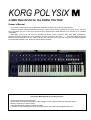
KORG POLYSIX
A MIDI Retrofit Kit for the KORG POLYSIX
Owner’s Manual
"Korg USA proudly announces the PS6-MRK MIDI Retrofit Kit for the Korg Poly-6 Synthesizer.
Thanks to modern software/hardware technology, a great classic analog synthesizer, the Korg Poly-6, has now
been upgraded with one of the most advanced and comprehensive MIDI Retrofits ever devised for a pre-MIDI
synthesizer.
With MIDI, your Poly-6 can now join the MIDI revolution, easily connecting with other MIDI synthesizers,
expander modules, sequencers, drum machines, personal computers and more ... " - so far the original text of the
MIDI retrofit kit produced by Korg in 1986. This has now come true once more with the present retrofit kit designed
by Ricard Wolf (Sweden) and Johannes Hausensteiner (Austria).
Polysix M - MIDI-upgrade for the Korg Polysix:
• Comprehensive MIDI implementation:
Note number, bend and mod wheels, pedals, arpeggio clock, program change and program dumps.
• Memory expansion to 128 programs
• Individual parameter update in realtime via MIDI
• A number of other enhancements such as sustain pedal, edit recall and arpeggiator MIDI sync.
Features
MIDI IN functionality: note on, note off, all notes off, bend wheel, mod wheel, program change, sustain pedal,
chord memory pedal, arpeggio switch, MIDI clock, start and stop (for the arpeggiator), sysex program dump,
mode messages, active sensing.
MIDI OUT functionality: note on, note off, all notes off, bend wheel, mod wheel, program change, sustain pedal,
chord memory pedal, arpeggio switch, sysex program dump, active sensing.
Individually selectable MIDI in and out channels 1..16.
Omni on/off, local on/off, and poly/mono mode messages received.
Arpeggiator can sync to MIDI clock at one of eight different clock rates.
Arpeggiated notes are sent over MIDI OUT.
Expands memory to 128 programs, grouped in 4 groups (1..4) of 4 banks (A..D) of 8 programs (1..8).
Edit recall functionality.
Individual parameter update in realtime via MIDI.
Chord memory pedal can now function as sustain pedal (switchable) with automatic pedal polarity detection.
Sysex dumps in banks of 32 or 128 programs can be sent and received.
128 program tape dump available, as well as 32 program format compatible with the original Polysix.
8 selectable key assign modes; dual and triple voice capability: up to three voices can be layered on the same note
for fatter polyphonic sound.
Programmable noise generator.
Programmable bend wheel (VCO/VCF).
Programmable mod wheel (VCO/VCF/VCA).
2
Connections
Rear panel MIDI jacks:
1) MIDI IN
Connect to MIDI Out of other synthesizer, computer, etc.
2) MIDI OUT
Connect to MIDI In of other synthesizer, computer, etc.
3) MIDI THRU
MIDI Thru delivers a copy of the signal received at MIDI In.
4) VCF fcM IN
The VCF fcM IN jack can act as a modulation pedal. It applies the same effect as the mod wheel without taking
the hands off the keyboard.
5) CHORD MEMORY
The Chord Memory footswitch input can act as a HOLD footswitch now. Switch polarity is detected automatically
during power on. So be sure to connect the footswitch before powering on. Can be set to Chord Memory operation.
3
Features and Functions
1) INTRODUCTION
An important goal for the Polysix M has been to retain the original character of the instrument while at the same
time expanding its functionality. The machine is operated in the same way as the original Polysix with the sole
exception of the new functions, in order for all users to feel at home. All sound parameters (VCO, VCF, VCF, MG,
EG, EFFECTS, BEND, TUNE and OUTPUT) operate exactly as before, and these will not be discussed further in
this manual. The arpeggiator works in exactly the same way as before, apart from the fact that it is now possible to
synchronize it to a MIDI clock (e.g. from a drum machine or sequencer).
2) NEW CONNECTORS
On the rear panel of the Polysix M there are three DIN connectors on the left hand side of the panel (rear view).
From left to right these are MIDI THRU, MIDI OUT, and MIDI IN. (This order is employed by most manufacturers.)
All data sent to the synthesizer is received via MIDI IN and all MIDI data that the synthesizer transmits is sent via
MIDI OUT. MIDI THRU delivers a carbon copy of the received data at MIDI IN and is used for daisy-chaining
several instruments from a single MIDI source.
3) MEMORY
The original Polysix had 32 memory locations (programs) organized in 4 banks of 8 programs each (4 x 8 = 32).
This organization has been retained in the Polysix M but in order to increase the memory to 128 programs, the
memory has been subdivided into four groups. In this way one obtains 4 groups x 4 banks x 8 programs = 128
programs total.
The memory group currently selected is indicated by one of the LEDs 1..4 flashing. To select another memory
group:
(1) Press MANUAL and hold it.
(2) At the same time press one of the buttons 1..4. The corresponding LED will start flashing indicating the currently
selected group.
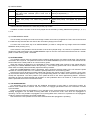
Example:
The currently selected program is group 3, program B4. This is indicated by LED 3 flashing with B and 4 being
constantly illuminated. To change to, let’s say, group 3, program C7 it is only necessary to press C and 7 as usual
since group 3 is already selected.
In order to, say, select group 1, program A5:
(1) Press and hold MANUAL.
(2) Press 1. "1" starts to flash indicating memory group 1.
(3) Release MANUAL and press A and 5 as usual.
To store a program at a memory location press WRITE as usual and then the program number (make sure that
the WRITE switch is in the WRITE ENABLE position).
Example:
The currently selected program is group 2, program D3. To store this program at location D6 instead:
(1) Press WRITE. WRITE starts to flash.
(2) Press 6. WRITE stops flashing and the program has been stored.
4
To store the program in group 1, program A1 instead:
(1) Press WRITE. WRITE starts flashing.
(2) Select memory group 1 by holding MANUAL and pressing 1. 1 starts to flash indicating memory group 1.
(3) Release MANUAL.
(4) Press A to select bank A.
(5) Finally press 1 to store the program. The WRITE LED will go out.
If the wrong group or bank is selected, simply move the WRITE switch to the WRITE DISABLE position and then
back to the WRITE ENABLE position, causing the WRITE LED to go out. Then restart the operation.
In this manual program numbers will be referred to as, for instance, 3C4 meaning "memory group 3, bank C,
program 4".
4) EDIT RECALL
Imagine the following situation:
You have created wondrous new sound by editing program 1A4. By mistake you press 5 causing the synthesizer
to immediately call up program 1A5 and erasing your hard worked edit.
In order to avoid this type of frustration the latest edit is saved in a special memory location in the machine, the
edit recall buffer. This is indicated by the MANUAL LED flashing. In order to recall the latest edit at any time:
(1) Press and hold MANUAL.
(2) Press 8. MANUAL will start flashing and the edited sound will be fetched for continued editing.
Example:
Assume program 2B4 is a string patch. Upon selecting this patch you notice that the release time is a bit too
short. Adjust this using the RELEASE knob. By doing this the sound is also copied into the EDIT RECALL buffer,
this is indicated by MANUAL flashing. You now want to save your new patch to another program location, but do not
know which locations are free. Thanks to the EDIT RECALL function it is now possible to examine the other
programs while the edit is kept safe in the edit recall buffer. Eventually you find that 4D5 is available. In order to
fetch the edit hold MANUAL and press 8. The edited string patch is now fetched from the edit recall buffer and
MANUAL begins to flash to indicate that an edit sound is being heard. After this the patch can be stored at the
memory location as usual.
To sum up:
- As soon as a patch is edited it is saved in an edit recall buffer.
- The contents of the buffer can be retrieved at any time using MANUAL-8.
However, note that if you press MANUAL (on its own) in order to make the front panel ’live’ (the MANUAL LED
lights up), changes are not saved in the edit recall buffer. There is no need since the patch is available on the panel
itself and can be retrieved simply by pressing MANUAL.
Additionally, please note that only changes made to the VCO, VCF, VCA, MG, EG, and EFFECTS parameters
are saved in the edit recall buffer since the settings of the other knobs and switches are not part of a program patch.
5
5) KEY ASSIGN FEATURES
No need to worry - POLY, UNISON, and CHORD MEMORY work just as before - with, however, some new
optional functionality.
This section is a bit in-depth technical; if you do not understand what is going on, just skip to the next section.
Upon powering up these settings are the same as for the original Polysix.
First of all, what is a synthesizer voice? It is not a little dwarf squashed away in a corner of the machine! Instead,
we can imagine a choir of 6 people. Let’s assume we are dealing with super-vocalists who can cover the whole
tonal range of bass to soprano. This choir could sing in several different ’modes’. They could sing six separate
parts. Or they could all sing the same part. Or they could sing a three-part song, with two choir members singing
each part. Or they could...
As long as they limit themselves to the physical limit of six notes at once, they could sing anything in any
combination.
The Polysix operates in much the same manner. We can play at the most six notes at once since we have six
voices in the machine. How these voices are handled is selected by the key assign mode.
The key assign mode describes how the synthesizer will react to the keys played. Are all notes to be heard
individually (POLY), or should only one be heard but with all six voices at once (UNISON), or...
Even in the POLY mode there area few variants. What happens, for instance, if more than 6 keys are
depressed? Should the last keys pressed be ignored so that none of the first notes heard will be lost, should the last
6 keys to be pressed always be heard so as not to ’lose’ any notes?
In many cases this is set by the manufacturer of the instrument and cannot be changed. The Polysix M however
offers the possibility of adjusting the key assign mode to suit the style of music and playing.
This is done in the following manner:
When pressing POLY, UNISON, or CHORD MEMORY hold it down, which will allow the key assign mode to be
adjusted by pressing A..D and 1..6.
The following functionality is available:
(*) indicates that this is a power-up default setting. These are the same as the key assign modes in the original
Polysix.
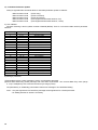
A) POLY MODE:
Button
A
B
C
D
LED off
LED on
When a new key is pressed the next voice in turn is The synthesizer always selects the lowestassigned (cyclic mode). (*)
numbered non-sounding voice (reset-to-zero).
No voice memory. (*)
If the same key is pressed several times, the
same voice is used (memory).
If more than six keys are depressed, only the oldest If more than six keys are depressed, only the last
are heard.
are heard. (*)
The MG delay is retriggered only when all keys The MG delay is retriggered as soon as a new key
have been released (and a new one depressed). (*) is depressed.
These functions can be enabled/disabled by pressing the corresponding button (while POLY is depressed).
In addition to this LEDs 1..3 show how many voices are played for each key depressed:
1: SINGLE - only one voice per key (*)
2: DUAL
- two voices per key.
3: TRIPLE - three voices per key.
These are selected by pressing 1, 2, or 3 (while POLY is depressed).
Note that the polyphony of the instrument decreases in the DUAL and TRIPLE modes (three-note polyphony in
DUAL and two-note polyphony in TRIPLE).
6
B) UNISON MODE:
Button
A
B
C
D
LED off
LED on
Single trig. The voices are retriggered only when all Multi trig. The voices are retriggered as soon as a
keys have been released (and a new one is new key is depressed. (*)
depressed).
See C.
Last key priority. The last key pressed is heard. (*)
( Only if B is off )
Lowest note priority. The lowest key pressed is Highest note priority. The highest key pressed is
heard.
heard.
( See POLY MODE D )
These modes are selected in the same way as the poly modes.
In addition to this the number of voices to be played can be selected by holding UNISON and pressing 1, 2, 3, 4,
5, or 6.
C) CHORD MEMORY MODE:
This is actually a monophonic mode even though a whole chord can be programmed. This is due to the fact that
it is ONE sole key that sets the root note for the chord when playing in this mode.
A..D thus work in the same way as in UNISON MODE. (In order to change the key assign mode hold CHORD
MEMORY while pressing A..D .)
In this mode it is not possible to set the number of voices to be played using 1..6, however, it is possible to select
whether the pedal connected to the CHORD MEMORY input on the rear of the instrument will function as a sustain
pedal or chord memory pedal - see below.
5) SUSTAIN PEDAL
The greatest omission from the original Polysix is without doubt the lack of a sustain pedal input. This has been
corrected in the Polysix M. The pedal connected to the CHORD MEMORY input on the rear of the instrument can
function either as a sustain pedal or as a chord memory pedal.
When the machine is switched on, the pedal will be set to sustain pedal mode (contrary to the original Polysix).
By holding the CHORD MEMORY button and pressing 1 chord memory pedal mode can be selected. In order to
switch back to sustain pedal functionality repeat the same procedure.
When the CHORD MEMORY button is depressed, LED 1 shows the selected mode: LED 1 off means the pedal
operates as a sustain pedal. LED 1 on means the pedal operates as a chord memory pedal.
Note that the Polysix M will accept both pedals with opening and closing (make or break) contacts. Upon power
up the machine assumes the pedal is in the ’up’ (not depressed) position, no matter which electrical state (open or
closed) this represents. The other position of the pedal will then be the ’down’ (depressed) position. Therefore,
remember to keep the pedal released and plugged in to the synthesizer when it is turned on, or else it is possible
that the pedal will seem to be inverted when used.
6) THE ARPEGGIATOR
The arpeggiator works as before with the additional functionality of being able to synchronize to MIDI, for
instance from a MIDI drum machine. See the section on arpeggio parameters below for information on MIDI
synchronization.
Please note that when the arpeggiator is on it operates on the notes pressed on the keyboard and sends the
resulting arpeggiation out via MIDI. Incoming MIDI data is received as usual, even when the arpeggiator is
operating. It is thus not possible to arpeggiate over incoming MIDI notes; however it is possible for the arpeggiator
to play an external synthesizer connected to MIDI OUT.
Also note that it is now possible to have HOLD selected while the arpeggiator is operating.
7
7) MIDI and TAPE ENABLE
In order to select MIDI channels etc. the machine is switched into TAPE ENABLE mode.
In contrast to the original Polysix it is possible to play the machine and edit sounds even in TAPE ENABLE
mode. It is not possible to select (or write) programs or change the key assign mode. The arpeggiator and HOLD
functions operate however.
Additionally the TAPE ENABLE mode is of course used when saving/loading programs to/from tape. This is
done in much the same way as before, so only changes from the original Polysix are described here.
8) SAVE/LOAD PROGRAMS TO/FROM TAPE
Switch the machine to TAPE ENABLE mode. Make sure that the POLY, UNISON, and CHORD MEMORY LEDs
are off. If not, press the corresponding button.
If the TO TAPE, FROM TAPE, or VERIFY buttons are pressed, the corresponding operation will be performed.
Note however that the whole memory of 128 programs is saved. (Note: it is not possible to load a 128-program
dump made this way into a original 32-program Polysix). For transferring programs in groups of 32, for instance in
order to load sound data from an original Polysix dump, memory group 1..4 must be selected first.
Example 1:
In order to load a 32-program dump into memory group 3:
(1) Switch the machine to tape enable mode.
(2) Press 3. 3 lights up and indicates that memory group 3 has been selected.
(3) Press FROM TAPE as usual and start playing the program tape. The 32 programs on tape are now loaded into
memory group 3. This is indicated by FOUND and LOADING lighting up when the data has been found on the
tape. 1..8 will then light up as usual while loading.
Example 2:
To save all 128 programs on tape.
(1) Switch the machine to tape enable mode.
(2) Start the tape recorder in record mode.
(3) Press TO TAPE. 1..8 will now light sequentially four times in a row to show that the data is being sent to the tape
recorder.
(4) Stop the tape recorder.
Just as before it is advisable to verify that the data has been recorded correctly using the VERIFY function as
usual.
It is also possible to dump programs via MIDI to a MIDI sequencer or MIDI data filer. In order to do this press
MANUAL instead of TO TAPE to start the dump.
In order to load back program data via MIDI it is only required to transmit the data via MIDI to the Polysix M.
Upon receiving the data it will be automatically stored in the internal memory.
Example:
To send memory group 2 to a computer via MIDI for further storage to disk for instance:
(1) Connect the Polysix M MIDI OUT connector to MIDI IN on the computer.
(2) Prepare the computer for data reception.
(3) Switch the Polysix M to tape enable mode.
(4) Press 2. Memory bank 2 is now selected, indicated by LED 2 lighting up.
(5) Press MANUAL. Data for the 32 programs in memory group 2 are now sent to the computer. MANUAL remains
lit for the duration of the dump.
If 2 were not pressed in stage 4, the whole memory of 128 programs would have been sent.
To store a program dump in the Polysix M simply send the data to the synthesizer. The dump will be written to
memory automatically, provided that the write switch is in the WRITE ENABLE position.
See the Polysix M MIDI implementation for the data format. MIDI commands are also available to request the
synthesizer to dump its programs.
8
9) MIDI OUT PARAMETERS
To set the MIDI OUT parameters press POLY in tape enable mode. POLY will light up indicating that the MIDI
OUT parameter mode has been selected.
The following parameters are available:
A) MIDI FILTER
LEDs A..D indicate MIDI filters. MIDI filters inhibit certain MIDI data from being transmitted. The following filters
are available:
A - note data (note on/note off/all notes off)
B - wheel data (bend and mod wheels)
C - program change
D - pedal (sustain pedal and chord memory pedal)
When the respective LED is illuminated the corresponding information is transmitted, otherwise not. Press the
corresponding button to toggle the filter on/off.
B) MIDI OUT CHANNEL
The MIDI OUT channel is indicated on 1..8 . Channel numbers above 8 are indicated by the corresponding LED
flashing. To obtain the selected channel number in this case add 8 to the LED flashing. To change channels simply
press the corresponding button. For channel numbers above 8 press the same button twice.
Example:
Channel 9 is selected. This is indicated by LED 1 flashing (1 + 8 = 9). In order to change to channel 13:
(1) Press 5 (13 - 8 = 5). 5 lights up indicating channel 5.
(2) Press 5 again. 5 starts flashing indicating channel 13.
10) MIDI IN PARAMETERS
To set the MIDI IN parameters press UNISON in tape enable mode. UNISON will light up indicating that the MIDI
IN parameter mode has been selected.
The following parameters are available:
A) MIDI FILTERS
These work as the corresponding MIDI OUT parameters but of course select what should be received by the
machine.
Example:
To turn off reception of program change messages:
(1) Switch to tape enable mode and press UNISON. UNISON lights up indicating MIDI IN parameter mode.
(2) The program change reception filter status is shown on LED C. If this LED is not lit, program change messages
are not received.
(3) Otherwise press C to turn the LED off.
B) LOCAL
Local mode is indicated on MANUAL. If the MANUAL LED is on, the synthesizer operates "as usual", i.e. the
keyboard, wheels, and pedal control the machine. By turning local mode off (by pressing MANUAL in MIDI IN
parameter mode, turning off the LED), all key depressions, bend and mod wheel changes, and pedals will only be
sent via MIDI (the corresponding MIDI OUT filters permitting) and not to the sound generating circuits in the
synthesizer. This can be useful in sequencing and master keyboard applications.
Note: The synthesizer will always respond to incoming MIDI data no matter whether LOCAL is on or off.
9
C) OMNI
The WRITE LED indicates omni mode. When the WRITE LED is on omni mode is selected (’omni on’) and the
synthesizer disregards the channel number of incoming MIDI data resulting in data being received from all MIDI
channels. When omni mode is off (WRITE LED is off) MIDI data is only received on the channel indicated by 1..8.
Note that local and omni modes can be controlled via MIDI using the LOCAL and OMNI MIDI commands (see the
Polysix M MIDI implementation).
D) MIDI IN CHANNEL
The MIDI IN channel is indicated and selected in the same manner as the MIDI OUT channel.
11) ARPEGGIATOR PARAMETERS
To set the arpeggiator parameters press the CHORD MEMORY button in tape enable mode. CHORD MEMORY
lights up to indicate that arpeggiator parameter mode has been selected.
The following parameters are available:
A) NORMAL/MIDI CLOCK
This is indicated on the MANUAL LED. When MANUAL is lit, this means that the arpeggiator is controlled using
the ARPEGGIATOR SPEED knob on the front panel (or the ARPEGGIO TRIG IN connector on the rear panel if
something is connected to this connector). If MANUAL is not lit, clock pulses are derived from the incoming MIDI
clock.
Note that when the machine is in MIDI clock mode (MANUAL not lit) and the arpeggiator is on, it will not start
until a START (250) or CONTINUE (251) MIDI message has been received. In the same way the arpeggiator will
stop when a STOP (252) message is received. Sequencers and drum machines usually send these messages
when they are started and stopped.
B) STEP SPEED
LEDs 1..8 indicate how fast the arpeggiator runs when synched to MIDI:
LED
one step is equivalent to
1
32nd note triplet
2
32nd note (demisemiquaver)
3
16th note triplet
4
16th note (semiquaver)
5
8th note triplet
6
8th note (quaver)
7
quarter note triplet
8
quarter note (crotchet)
The step speed is selected by pressing the corresponding button.
C) HOLDOFF TIME
A..D indicate the holdoff time. This is, to put it precisely, the time after the arpeggiator has been retriggered by
pressing a new key (after all keys have been released) that it will not respond to an external clock pulse.
Simple, isn’t it! For those interested in arpeggiator details there is a further explanation below; otherwise simply
disregard this parameter!
The full story is as follows: Normally when all keys have been released and a new key (or several keys) is
pressed the new note to be arpeggiated should be triggered immediately without waiting for a clock pulse.
Otherwise there would be the risk of missing the first arpeggiated note if the key was pressed the millisecond after a
clock pulse was received. The arpeggiator would seem to miss a step. On the other hand, another possibility is that
a key is depressed a few milliseconds before a clock pulse is received. In this case a double trig would be the result
- one trigger caused by the key pressed and another by the clock pulse. The result of the double trig would be that
the arpeggiator would advance an extra step for no apparent reason. (This problem does not arise when the
arpeggiator is clocked internally as the internal clock generator is reset every time a new key is depressed - try for
yourself by setting a slow arpeggio rate and retriggering the arpeggiator clock generator by pressing a key on the
keyboard!) In order to avoid double triggering when keys are pressed just before a clock is received a holdoff period
has been implemented which disables clock pulse reception for a certain length of time after the arpeggiator has
been triggered by a key depression. The holdoff time can be set using A..D, from about 10ms at setting A up to
about 35ms at setting D. The power-on default is D.
In practice the holdoff value should make little difference but if you experience strange triggering when using the
arpeggiator with MIDI sync, experiment with other holdoff settings.
10
12) PROGRAMMABLE NOISE GENERATOR
A WHITE NOISE noise generator is built on the MIDI pcb. Control is fully memorized with patches. It is switched
on when waveform sawtooth or pulse is selected and PWM SPEED is greater than "1". PWM SPEED acts also as
NOISE VOLUME control. The noise signal is AC coupled and fed to the VCO saw/pulse/sub osc. summing node of
each voice on KLM-366 via a 33k resistor. The noise is generated digitally by means of a looped shift register.
13) PROGRAMMABLE BEND WHEEL (optional, see modifications section)
When doing this modification, the BEND wheel can be switched to either bend the VCO (as with the original
Polysix) or to bend the VCF. This setting is stored along with each patch. The BEND INTENSITY pot is only active
in VCO mode. VCF bending mode is always full range.
14) PROGRAMMABLE MOD WHEEL
The MOD Wheel (and also MIDI Modulation IN) will follow the programmed LFO MODE switch. This means you
can select LFO MODE ’VCA’ and MG LEVEL ’0’. You then may add tremolo manually with the MOD wheel.
15) MODULATION PEDAL IN
You may modify the VCF fcM IN for an input for a modulation pedal (10k log):
• tip is -5V (via 1k safety resistor)
• ring is CV input
• sleeve is GND
Note: - The modulation pedal follows - like the modulation wheel - the programmed LFO MODE.
- The effect achieved by the mod pedal is available only locally; there is no control change command sent via
MIDI.
16) TEST MODE
(ONLY FOR SERVICE TECHNICIANS OR THE TECHNICALLY INTERESTED)
In the original Polysix there are two different test modes.
One is started by setting the switch on the KLM-367 circuit board in the TEST position and switching the front
panel TAPE ENABLE switch to the ENABLE position and then back to the DISABLE position. This is used to adjust
the programmer DAC.
The other test mode is started by jumpering pins DB7 and P17 using a diode (cathode towards DB7) on the
8049 processor on the KLM-366 circuit board (this can be done on the keyboard connector CN04). In this mode the
CV DAC is set to generate 0V, 2.5V, or 5V depending on the position of the OCTAVE switch (16’ results in 0V, etc.).
This mode is used to check the CV DAC and is not described in the service manual.
In the Polysix M both these modes have been merged into one which performs both tasks. The test mode is
started in the following manner:
(1) Enter tape mode by switching the TAPE switch to the ENABLE position.
(2) Press 5, 6, 7, and 8 at the same time.
(3) Hold these four buttons and exit tape mode (TAPE DISABLE).
(4) The machine is now in the test mode and cannot be operated in the normal manner.
To adjust the programmer DAC it is still necessary to switch the KLM-367 switch to the TEST position.
To exit the test mode press A (or cycle power).
11
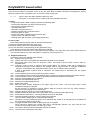
17) Individual Parameter Update
Newly recognized MIDI commands allow for individual parameter update in realtime:
MIDI Controller CC06
MIDI Controller CC96
MIDI Controller CC97
MIDI Controller CC98
MIDI Controller CC99
(DATA entry)
(DATA increment)
(DATA decrement)
(Non Registered Parameter Number, fine)
(Non Registered Parameter Number, coarse)
A) Use of NRPN
Paramter selecting is done by MIDI controller CC98/99 (NPRN). There is a conversion table used for parameter
seletcion:
62h (CC98)
0
1
2
3
4
5
6
7
8
9
10
11
12
13
14
15
16
17
18
19
20
21..127
63h (CC99)
0..5
6..11
12..17
18..23
24..29
30..35
36..41
42..47
48..53
54..59
60..65
66..71
72..77
78..83
84..89
90..95
96..101
102..107
108..113
114..119
120..125
126..127
PolySix parameter name
OCTAVE
WAVEFORM
PW/PWM
PWM SPEED
SUB OSC
FILTER CUTOFF
FILTER RESONANCE
EG INTENSITY
KBD TRACKING
VCA EG MODE
ATTENUATOR
BEND MODE
MG SPEED
MG DELAY
MG LEVEL
MG MODE
ATTACK
DECAY
SUSTAIN
RELEASE
EFFECT MODE
EFFECT SPEED
B) Editing a parameter
(1) Send NRPN (CC98, CC99) message to select corresponding parameter.
(2) Send either Data Entry (CC06) message with new value of parameter. The received Data Entry value (range
0..127) is multiplied by two to achieve the whole byte range (0..254) .
OR (alternatively or additionally) send Data In/Decrement message to do UP/DOWN editing.
Note: - Only the highest bits of a Data Entry message will be significant for a switch parameter.
- No fiddling with bits or similar is necessary.
12
PolySixM PC based editor
There is also an editor for PolySixM. It runs on any PC under DOS. For MIDI connection to PolySixM you need a
MPU-401 (UART mode) compatible card. To invoke the editor simply type:
P6 [o] ... with no option the editor defaults to MPU-401 card
with option ’o’ the editor works in offline mode (no PolySixM connected)
1) Tasks:
In conjunction with the editor PolySix performes the following tasks:
- Downloading edit buffer (currently produced sound)
- Downloading complete patch set
- Uploading edit buffer
- Uploading complete patch set
- Edited-to-original-sound compare function
- Naming a patch (on disk)
- Saving and loading complete patch set to/from disk
- Playing a note from within the editor
- Working offline with the editor (rearranging patches etc.)
2) How to edit:
Patch editing with the PolySix editor is done the following way:
(1) Select the desired parameter with cursor keys.
(2) Up/down editing is done via PGUP/PGDN keys.
(3) You may also enter a value directly (analog parameters only):
press SPACE and enter the desired value followed by ENTER.
(4) Some functions are executed via a command line which appears in the upper left of the screen. ESC leaves the
command line without any action. Backspace is supported, cursor keys are not.
3) Supported Functions:
Following functions are available within P6.EXE:
<F1> .. displays short online help.
<F2> .. selects new patch on PolySixM and downloads edit buffer from PolySixM.
<F3> .. Edits patch name. Each patch can be given a name. This name is saved to disk; it has no effect on
PolySixM itself.
<F4> .. Compare. If this function is selected during sound editing, the original sound will be uploaded to
PolySixM temporarily. Further editing is not possible while in compare mode. A message "COMPARE
- press F4" is displayed in the command line area. Press <F4> to switch back to edit mode.
If ESC is depressed compare mode is cancelled. The edited sound is discarded and the original
sound is kept.
<F5> .. Current edited sound is saved (under same patch number).
<F6> .. Current edited sound is saved under different patch number.You will be prompted for new patch number.
<F7> .. The whole patch memory of PolySixM (128 patches) will be downloaded from PolySixM.
<F8> .. Plays the selected MIDI note for 500msec.
<F9> .. Switches the selected MIDI note on.
<F10> .. Switches the selected MIDI note off.
<sF1> .. Redraw the screen.
<sF2> .. Edits the patch number displayed in the upper right of the screen. This does NOT send a PGM
CHANGE message to PolySixM.
By this function it is possible to change patches within the memory of the PC e.g. when working in
offline mode (rearranging patch numbers etc.).
<sF3> .. Displays all patch names of currently loaded patch set.
<sF4> .. Recalls the backup edit buffer to the current patch which contains the last edited sound.
<sF5> .. Downloads the edit buffer (= currently produced sound) from PolySixM.
<sF6> .. Changes the MIDI channel for communication with PolySixM.
When P6.EXE is started CH #1 is automatically selected.
<sF7> .. Uploads the current COMPLETE patch set to PolySixM. Be careful as all 128 patches in PolySixM will
be overwritten (if Write Enable is ON).
<sF8> .. Changes the MIDI note number for playing sounds on PolySixM.
When P6.EXE is started note number #60 (C5) is automatically selected. You may enter the note
number as a (decimal) number or as a key (e.g. G#7).
<sF9> .. This loads a previously stored PolySixM sysex file to memory.
<sF10> .. This stores the current patch set to disk.
13
4) FileFormats:
The PolySix editor program supports several different file formats:
- raw sysex dump file format (includes sysex header; *.SYX)
- extended PolySix editor file format (incl. patch names; *.P6)
- PolySix Patch Chart file format (ASCII text; *.TXT)
- Patch Names File (ASCII test; *.NAM)
For a detailed description of these formats see below. When executing <sF9> or <sF10> you get a menu from
where you can choose different options. When pressing <x> or <ENTER> you leave the menu and nothing
happens. When entering a string of more than one character this is interpreted as file name for Load/Save
operation. Note that the file name extension (.SYX, .P6, .TXT, .NAM) is added automatically when the entered string
contains no dot (’.’). The default file format after starting PolySixM editor is raw SysEx dump. It is further possible to
select a specific group of patches (group 1..4), 32 patches each (A1..D8) to load/save from/to disk. This makes it
possible to combine legacy (32 patch) tape dumps to full 128 patch sets. There are also functions provided for
viewing directory contents or even a complete temporary DOS session.
A) Raw SysEx file format (default extension .SYX):
- sysex header:
F0
Start of Exclusive
42
Manufacturer ID Korg
0n
n .. MIDI channel number
0g
g .. patch group: (0 .. all groups)
- patch data:
16 bytes patch data * 32 (one group only); each byte saved as two bytes with high nibble 0
or:
16 bytes patch data * 128 (no group selected); each byte saved as two bytes with high nibble 0
- checksum:
cc
checksum byte (0 .. 7F)
- sysex trailer:
F7
End of Exclusive
The resulting file size is:
4 + 16 * 32 * 2 + 1 + 1 = 1030 bytes (single patch group)
4 + 16 * 128 * 2 + 1 + 1 = 4102 bytes (all groups)
B) Extended PolySix Editor file format (default extension .P6):
16 bytes patch name
16 bytes patch data (as described above)
This is repeated 32 times for 32 patches (one group) or 128 times (all groups). The resulting file size is
32 * 32 bytes = 1024 bytes (one group)
128 * 32 bytes = 4096 bytes (all groups)
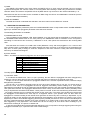
C) PolySix Patch Chart file format (default extension .TXT):
This is a plain text file which reproduces the setting charts in ASCII text. The format is the same as displayed
within the editor. Example:
Patch name: Brass
Patch #: A1
+----+----+----+----+----+----+----+----+----+----+----+----+
|
| 16’ SAW 10
0
OFF| 4
2 +1.2
7 | GAT
0 |
|
| OCT WAVE PW/M SPD SUB| CUT RES INT KBD|MODE ATT|
|TUNE|
V C O
|
V C F
| V C A |
+----+----+----+----+----+----+----+----+----+----+----+----+
| VCO| o
6
2
2
VCO| 4
5
7
10 | OFF
0 |
|
|
FREQ DEL LVL MODE| ATT DEC SUS REL|MODE SPD|
|BEND|
M G
|
E G
| E F F |
+----+----+----+----+----+----+----+----+----+----+----+----+
When you print this file you get pages with 4 patch charts each.
D) Patch names file format (default extension .NAM):
This is a plain text file, too. You find there the names of your PolySix patches.
14
5) Edit buffer:
The edit buffer consists of 16 bytes with the following layout:
Fourteen bytes analog parameters:
offset
00
01
02
03
04
05
06
07
08
09
10
11
12
13
Parameter
Effects Speed/Intensity
VCF Cutpff Frequency
VCF Envelope Intensity
VCF Resonance
EG Attack
EG Decay
EG Sustain
EG Release
VCF Keyboard Tracking
Pulsse Width / PWM Depth
PWM Speed
MG Frequency
MG Delay
MG Level
Two bytes of switch parameters:
offset
14
15
b7
b6
MG Mode
b5
b4
Sub Oscillator
Programmable Attenuator
b3
b2
Waveform
B.Mode
b1
b0
Octave
Effects Mode
VCA Md
15
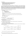
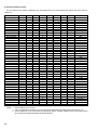
6) Switch parameter values:
As the values of the switch parameters are not always what you would expect the values are given here for
reference:
Parameter
VCO Octave
b7
b6
b5
b4
VCO Waveform
Sub Oscillator
MG Mode
0
0
1
1
0
0
1
1
b3
b2
0
0
1
1
0
1
0
1
b1
0
0
1
1
0
1
0
1
OFF
1 Oct dn
2 Oct dn
2Oct dn *
0
1
0
1
VCA
VCF
VCO
VCO+VCF *
0
1
Effects Mode
0
0
1
1
Bend Mode
Notes:
16
0
1
0
0
0
0
0
0
0
0
1
1
1
1
1
1
1
1
0
0
0
0
1
1
1
1
0
0
0
0
1
1
1
1
Value
16’
8’
4’
2’ *
PW
SAW+PW **
PWM
SAW+PW+PWM *
VCA Mode
Attenuator
b0
0
1
0
1
0
0
1
1
0
0
1
1
0
0
1
1
0
0
1
1
0
1
0
1
0
1
0
1
0
1
0
1
0
1
0
1
0
1
0
1
GATE
EG
OFF
Chorus
Phaser
Ensemble
VCO Bend
VCF Bend
-10 dB
-8 dB
-6 dB
-4 dB
-2 dB
0 dB
+2 dB
+4 dB
+6 dB
+8 dB
+10 dB
+12 dB ***
+14 dB ***
+16 dB ***
+18 dB ***
+20 dB ***
* These settings are not used.
** If D1 on KLM-366 is removed. You can shut off the pulse wave by setting the PW control to '10'.
*** These settings are not used during programming. When sending a MIDI Volume command (CC07)
all 16 values are taken advantage of (4bit resolution).
Modifications
1) GENERAL
In order to make the MIDI retrofit work some modifications have to be done to several modules of the Polysix.
There are additional modifications which are not related to MIDI. Some of them are mandatory, some of them are
optional. So please read this whole section carefully and decide then what you want to implement.
There are some things to do on the control panel pcbs. Although it seems to be a lot of work I recommend to
unmount all modules from the control panel lid. This is much safer when drilling the holes for the MIDI jacks. At this
occasion you can thoroughly clean the lid, knobs, and buttons.
There are basic solder skills necessary to do the following.
Additionally you need appropriate tools:
• small solder iron (max. 25Watts)
• solder
• desolder vacuum pump or solder wick
• pair of pliers
• pair of pincers
• pair of tweezers
• knife (cutter)
• various screwdrivers
• multimeter is helpful
For mounting the MIDI jacks you will need:
• hammer
• hard pointed tool
• drilling machine with 3.5mm, 6.5mm, and 14mm drills
• round file
• black permanent marker
All parts, wires, etc. are included in the kit. Check the contents of the kit against the packing list.
You will have to cut pcb traces. Be sure that they are really interrupted and there is no chance of coming
together again. A good way of doing this is to cut twice, 1mm apart and remove the remaining pcb trace in between.
Connecting two points to each other means to solder a wire from here to there (use the thin green wire supplied).
Be careful not to make any shorts to neighboring pins, etc.
If you are not sure whether you will be able to carry out the necessary steps, find someone who is experienced in
this kind of stuff.
Before you start working save all your patches to tape. Otherwise they will get lost. It is also a good idea to
thoroughly check the whole instrument. Turn every knob, press every button, etc. and make a note of any
anomalies. When you finished installation and some functions seem not working you will be glad if you know
whether they worked before or not.
When I speak of "upper" or "lower" end of a component I mean when viewing the Polysix in normal playing
position facing the keyboard ("upper" is side towards back, "lower" is side towards keyboard).
OK, here we go:
17
2) MANDATORY MODIFICATIONS
A) On KLM-366:
Enable voice gates in tape interface mode:
• Cut pcb trace IC4/pin1 to via (component side).
• Connect IC4/pin1 to IC4/pin16.
Separate UNISON LED from unison detune function:
• Remove R118 (10k).
• Connect IC5/pin13 to IC2/pin14.
• Connect IC2/pin15 to IC30/pin6.
Separate CHORD MEMORY pushbutton from footswitch input:
• Cut pcb trace to D3/anode (component side).
• Connect D3/anode to IC6/pin33.
B) On KLM-367:
Remove the backup battery. There is a lithium battery on the new MIDI pcb you received.
Disable mute circuit during tape interface mode:
• Cut pcb trace to IC5/pin3 directly at IC5/pin3 (solder side). Be sure not to damage the passing by pcb trace.
• Connect IC5/pin3 to IC5/pin7.
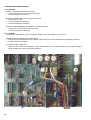
Connection cable to MIDI pcb:
• Solder the open ends of the supplied 10 way cable (drawing no. PS 6M 00 05 004) to the respective target
points on KLM-367 (refer to picture and drawing).
18
C) On KLM-369:
Feed the control voltages from the wheels into the multiplexer for A/D converting:
• Remove R16 (430k) and J4 (0 Ohm).
• Cut pcb trace to IC2/pin2 directly at pin2 (solder side).
• Cut pcb trace to IC2/pin4 directly at pin4 (solder side).
• Connect CN09/pin5 to IC2/pin4.
• Connect CN09/pin6 to IC2/pin2.
Note: These two connections require rather long wires. Route them on the component side of the pcb where you
can fix them below other components (e.g. a potentiometer).
D) On wheel assembly:
• Swap brown and orange wires of BEND pot.
• Disconnect two yellow wires from MOD pot. Leave them together and insulate the mending point with
shrinking tube.
• Disconnect red wire from BEND pot and connect to red wire of cable to J7 of MIDI pcb. Insulate with a piece
of shrinking tube.
• Disconnect blue wire from MOD pot and connect to middle pin of BEND pot. This blue wire will be quite short;
lengthen it with supplied piece of blue wire (40mm) and insulate with shrinking tube.
• Connect "upper" end of BEND pot to "upper" end of MOD pot. Use orange wire (140mm).
• Connect "lower" end of BEND pot to "lower" end of MOD pot. Use brown wire (140mm).
Refer to drawing no. PS 6M 00 05 005.
E) Mounting MIDI jacks:
These three DIN jacks are what you have waited for. Now you got them. The only thing you have to do is to drill
some holes into the back of your Polysix ...
To make this task easier I created a template which is part of the kit. Once more I recommend to unmount
everything from the top/back lid of the Polysix. Work is much safer then. Be sure that no filings are left in the
instrument!
(1) Unmount the control panel, knobs, rear jack assembly, power switch assembly, power supply pcb, power cable
hooks and take off the lid. Make notes or a sketch about connections and locations of components.
(2) Take off the cable clip on the inside of the lid. It is right on the same position where the MIDI jacks are going to
be.
(3) Take the template and fold it along the line.
(4) Hold the template against the lid: folded side on top of lid, MIDI jacks drawings on back side.
• Align left edge of template with edge of lid.
• Fix template in this position with adhesive tape.
• Take hammer and pointed tool and mark center points of holes to be drilled.
(5) Take off the template and drill the holes (good luck!).
• The big holes probably need some finish with the round file. Check size and shape with DIN jack and MIDI
cable.
• When you are satisfied with the shape of the holes paint the edges with black permanent marker.
(6) Before assembling the control panel with all the knobs, etc. make all modifications to KLM-369, KLM-370, and
KLM-371.
(7) Reassemble control panel.
19
3) OPTIONAL MODIFICATIONS
Besides MIDI there are following features on the MIDI pcb:
A) White Noise generator (programmable level):
• Solder the free ends of cable drawing no. PS 6M 00 05 003 to the "upper" end of R150 of each unit on KLM366 (refer to drawing). It is possible that noise is enabled in your patches. It is disabled when waveform PWM
is selected or when PWM SPEED setting at ’0’.
B) Waveforms Sawtooth and Pulse appearing simultaneously:
• Remove D1 from KLM-366.
Note: When Saw is selected the pulse wave is generated, too. To switch off the pulse wave turn the PW knob
fully clockwise (’10’). You have to check and reprogram your patches after this modification.
C) Programmable BEND wheel (selectable VCO or VCF bending).
On KLM-370 the EFFECTS MODE switch (OFF/CH/PH/EN) has to be coded onto two data bits:
• Remove D3.
• Mount two diodes (1N4148, supplied):
• D3A: anode to D1/anode; cathode to former D3/cathode
• D3B: anode to D2/anode; cathode to former D3/cathode
(cathode side is marked with a black ring).
Obtain signals from KLM-367 for decoding EFFECTS MODE:
• Desolder IC34 (4042) an replace with supplied DIL16 IC socket. Desoldering in best done by cutting each leg
of the IC and then removing each leg separately.
• On the wheel panel (e.g. above BEND Wheel) mount BEND Mode switch:
• Drill a hole (6.5mm / 1/2") and mount switch connected to cable PS 6M 00 05 005.
On the jack panel (at the rear):
• Disconnect orange wire from fcM In jack (you will loose this input in this case; it can be used for a modulation
pedal input, see below). Solder a single pin onto the end of this wire and put a piece of shrinking tube over it.
This single pin will be used to connect to the orange wire of cable PS 6M 00 05 005, which has a single
receptacle on its orange wire.
On KLM-366:
• Remove R50 (100k), R51 (150k), and C58 (0.01u).
• Cut pcb trace IC10/pin1 to (former) R50.
• Connect former R50/"upper" pin to former R51/"upper" pin.
Note: If you want to keep the fcM input, you have to connect the orange wire of cable PS 6M 00 05 005 via an
additional 33k resistor to KLM-366/IC13/pin2 instead (this is the summing node of the VCF cutoff frequency
control voltages). Additionally do not remove R50, R51, and C58 from KLM-366.
You will have to check and maybe reprogram the EFFECTS MODE setting of your patches.
If you do not want the BEND Wheel be programmable and leave the EFFECTS MODE as it is, do not
perform any of these modifications. Instead you have to remove the connection pins labeled J6 from the MIDI
pcb (solder side).
D) Modulation Pedal In jack:
On jack panel assembly:
• Replace the fcM In jack (see above) with supplied stereo jack connected to cable PS 6M 00 05 006 (you will
loose the fcM In function).
• Connect GND wire to neighboring jack (Arpeggio Trig In).
E) Make the BANK LEDs A-D equally bright when more than one LED is on:
On KLM-371:
• Remove R14 (470 Ohm), J12, J13, J16 (0 Ohm)
• Mount 0 Ohm or wire bridge into R14 location.
• Mount 470 Ohm into J12 location.
• Mount 470 Ohm into J13 location.
• Mount 470 Ohm into J16 location.
F) If you experienced the headphones being too loud you may replace KLM-368/R4 and R8 (1k) by 3k3.
20
4) MOUNT THE PS6M MIDI PCB INTO THE POLYSIX
When you have finished all modifications it is time to reassemble your Polysix and mount the heart of your MIDI
retrofit kit: the PS6M MIDI pcb.
(1) Reassemble the control panel (jack panel assembly, KLM-376, KLM-369, KLM-370, KLM-371, power cord), put
the lid in its place and connect all cables.
(2) Mount the wheel panel and connect to KLM-369/CN09.
(3) Mount KLM-366 board. Connect all cables with exception of CN05 (cable to KLM-367, green wires).
(4) Bring KLM-367 board in its position (do not screw it at this stage).
(5) Take the four 3x10mm standoffs and the insulation plate.
(6) Put the standoffs onto the 4 mounting holes of KLM-367.
(7) Lay the insulation plate onto the stand-off. This can be a bit tricky. You can make it easier if you glue the
standoffs to the insulation plate.
(8) Take the PS6M MIDI pcb and plug it onto KLM367/IC22 (Programmer CPU) socket and IC34 (4042) socket. Be
sure to have all pins correctly aligned!
(9) Screw the PS6M MIDI pcb together with KLM-367 be means of supplied 3x35mm screws to the chassis.
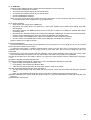
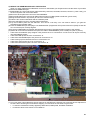
(10) Make all connections to KLM-367 first (also the cable to KLM366/CN05), then to MIDI pcb (refer to picture):
• Cable from KLM-366/IC6 (Key Assignor CPU) socket has to be connected to J2. Be sure to fit all pins correctly
into KLM-366/IC6 socket.
• Cable from MIDI jacks has to be connected to J3.
• Cable from KLM-366/R150(unit 0-5) has to be connected to J4.
• Cable coming up from KLM-367 has to be connected to J5.
• Cable from wheel panel has to be connected to J7.
• Cable from Mod Pedal In jack has to be connected to J8.
(11) You may have noticed that there are two trimpots on the MIDI pcb. Normally you would not have to adjust them
as this is done at testing the board before shipping. For reference the functions are given here:
• P1 sets the modulation intensity applied by MOD wheel, MOD pedal, and MIDI modulation.
• P2 sets the white noise source to VCO balance.
21
POLYSIX-M V2.1 MIDI IMPLEMENTATION (18.Mar.2000)
1) TRANSMITTED DATA
(A), (B), (C), or (D) means that the messages are only transmitted when the respective output filters are enabled:
(A) - note data
(B) - wheel data
(C) - program change
(D) - sustain pedal / chord memory pedal
nnnn is the midi output channel;
x
is don’t care
A) Voice Messages:
1001 nnnn
0kkk kkkk
1100 nnnn
0ppp pppp
1011 nnnn
0000 0001
0vvv vvvv
Control change
Mod wheel; no 1 (B)
1011 nnnn
0100 0000
0vvv vvvv
Control change
Sustain pedl;no 64(D) Value (0=off; 127=on)
1011 nnnn
0100 0100
0vvv vvvv
Control change
ChMem pedl;no70(D) Value (0=off; 127=on)
Note: Only one of sustain pedal/ch mem pedal will be transmitted,
depending on the setting of the CH MEM Pedal parameter.
1011 nnnn
0111 1011
0000 0000
Control change
All notes off (A)
Note: All notes off is transmitted:
A) When arpeggiator is stopped or started
B) When output channel is changed and (A) is enabled
C) When output filter (A) is turned off
1110 nnnn
0LLL LLLL
0hhh hhhh
Pitch bend (B)
LSB
MSB
Note: LSB is 0 if MSB<65, LSB=2*(MSB-64) if MSB>64
22
0vvv vvvv
Note on/off (A)
Note number (36..96)
Velocity (64=on;0=off)
Program change (C)
Pgm.
number
(0..127)
Note: The programs are arranged in the following order:
Pgm. chg. no
0 - 7: Group 1:Bank A:Programs 1..8
Pgm. chg. no
8 - 15: Group 1:Bank B:Programs 1..8
..
Pgm. chg. no 24 - 31: Group 1:Bank D:Programs 1..8
Pgm. chg. no 32 - 39: Group 2:Bank A:Programs 1..8
..
Pgm. chg. no112 - 127: Group 4:Bank D:Programs 1..8
Value (0..127)
B) System Exclusive:
1111 0000
0100 0010
0000 nnnn
0ccc cccc
0ddd dddd
..
1111 0111
System Exclusive
Korg ID
Device ID (MIDI channel)
Command Code (see below)
<data>
..
End of Exclusive
F0
42
0n
cc
dd
F7
Note: The only system exclusive messages transmitted are program dumps. These may be initiated by:
A) Pressing MANUAL in TAPE MODE when neither POLY, UNISON, CH MEM is lit.
B) Upon reception of a valid dump request command (see received data).
The following command codes may be sent:
C=0
sending all 128 programs
C=1, 2, 3, 4 sending memory group 1, 2, 3, or 4 respectively
The data format is as follows:
Each program consists of 16 data bytes. However, since these are in the range 0..255, they cannot be
transmitted in this form via MIDI. Therefore, each byte is broken down into two nibbles, and is sent low nibble first.
Each program therefore consists of 32 MIDI bytes in the range 0..15. The programs are sent in program number
order (see above: program changes). At the end of a dump a checksum is sent. This checksum is generated by
adding all the program data bytes (not MIDI bytes) in the dump and keeping only the 7 lowest bits. The checksum is
transmitted directly after the last program nibble. Thus all 128 programs constitute 128*16*2+1=4097 MIDI bytes
(the <data> segment above), whereas a single memory group (32 programs) is 32*16*2+1=1025 MIDI bytes
(including the checksum byte).
Example: 128 program dump:
1111 0000
Sysex
0100 0010
Korg ID
0000 nnnn
MIDI ch
0000 0000
Command code 0; 128 programs
0000 LLLL
Group 1, Bank A, Program 1, low nibble of 1. byte
0000 hhhh
Group 1, Bank A, Program 1, high nibble of 1. byte
0000 LLLL
Group 1, Bank A, Program 1, low nibble of 2. byte
0000 hhhh
Group 1, Bank A, Program 1, high nibble of 2. byte
..
0000 hhhh
Group 4, Bank D, Program 8, high nibble of 16. byte
0ccc cccc
Checksum of the preceding 128*16=2048 program data bytes
1111 0111
EOX
C) System Realtime:
1111 1110
Active sensing
Note: Active sensing is transmitted every 150ms
except during MIDI dump and tape operations.
2) RECEIVED DATA
(A), (B), (C) or (D) means that the messages are only recognized hen the respective input filters are enabled:
(A) - note data
(B) - wheel data
(C) - program change
(D) - sustain pedal / chord memory pedal
The mode messages (Control 122..127) will only be recognized on the set midi in channel, regardless of omni on or
off. This is noted in the tables below as (*).
nnnn is the midi input channel
x
is don’t care
23
A) Voice Messages:
1000 nnnn
0kkk kkkk
0xxx xxxx
Note off (A)
1001 nnnn
0kkk kkkk
0vvv vvvv
Note on/off (A)
Note number
Vel.(0=off,all othr=on)
Note: The Polysix-M will respond to the entire MIDI key range 0..127;
however notes generating higher pitches than 4’ key number 96 will be
reduced by octaves until they are within playable range.
1100 nnnn
0ppp pppp
1011 nnnn
0000 0001
0vvv vvvv
Control change
Mod wheel; no 1 (B)
Value (0..127)
1011 nnnn
0000 0110
0vvv vvvv
Control change
Data Entry; no 6
Value (0..127)
1011 nnnn
0000 0111
0vvv vxxx
Control change
Volume; no 7
Val.(0..127); 4bit reso
1011 nnnn
0100 0000
0vvv vvvv
Control change
Sustain pedl;no 64(D)
Val (0=off,all othr=on)
1011 nnnn
0100 0100
0vvv vvvv
Control change
Ch mem pedl;no70(D) Val (0=off,all othr=on)
1011 nnnn
0100 0101
0vvv vvvv
Control change
Arpeggiator sw; no 71 Val (0=off,all othr=on)
Note: The arpeggiator switch command has the same function as the
front panel ARPEGGIATOR button. Do not confuse it with the MIDI
start/stop commands.
1011 nnnn
0110 0000
0xxx xxxx
Control change
Data Increment; no96
1011 nnnn
0110 0001
0xxx xxxx
Control change
Data Decrement;no97 Value ignored
1011 nnnn
0110 0010
0vvv vvvv
Control change
NRPN fine; no 98
Value (0..127)
Note: Parameters are mapped via table (see ‘Individual Parameter
Update’ above)
1011 nnnn
0110 0011
0vvv vvvv
Control change
NRPN coarse; no 99
Value (0..127)
Note: Parameters are mapped via table (see ‘Individual Parameter
Update’ above)
1011 nnnn
0111 1010
0vvv vvvv
Control change
LOCAL command (*)
Val (0=off,all othr=on)
1011 nnnn
0111 1011
0xxx xxxx
Control change
All notes off (A) (*)
don't care
1011 nnnn
0111 1100
0xxx xxxx
Control change
OMNI OFF cmd (*)
don't care
Note: OMNI OFF also functions as all notes off.
1011 nnnn
0111 1101
0xxx xxxx
Control change
1011 nnnn
0111 1110
0000 0001
Control change
MONO ON cmd (*)
Only mono-1 recogniz
Note: MONO ON will set the Polysix-M in UNISON mode and turn all
notes off.
1011 nnnn
0111 1111
0xxx xxxx
Control change
POLY ON cmd (*)
don't care
Note: POLY ON will set the Polysix-M in POLY mode and turn all notes
off.
1110 nnnn
0Lxx xxxx
0hhh hhhh
Pitch bend (B)
LSB
Note: Pitch Bend has 8 bit resolution
24
Note number
Rel. velocity (ignored)
Program change (C)
Pgm. number (0..127)
Note: See ’Transmitted Data’ section for program order.
OMNI ON cmd (*)
Value ignored
don't care
MSB
B) System Exclusive:
1111 0000
0100 0010
0000 nnnn
0ccc cccc
0ddd dddd
..
1111 0111
System Exclusive
Korg ID
Device ID (MIDI channel)
Command Code (see below)
<data> (commands 10h..14h have no data)
..
End of Exclusive
F0
42
0n
cc
dd
F7
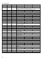
The following command codes are recognized:
Code
Meaning
Action
00h
01h
02h
03h
04h
10h
11h
12h
13h
14h
128-program dump follows
Memory group 1 dump follows
Memory group 2 dump follows
Memory group 3 dump follows
Memory group 4 dump follows
Request 128 program dump
Request memory group 1 dump
Request memory group 2 dump
Request memory group 3 dump
Request memory group 4 dump
Loads data into memory if WRITE is enabled
-"-"-"-"Sends 128-program dump (see ’Transmitted Data’ section)
Sends 32 programs of memory group 1 ( - " - )
Sends 32 programs of memory group 2 ( - " - )
Sends 32 programs of memory group 3 ( - " - )
Sends 32 programs of memory group 4 ( - " - )
20h
21h
22h
Request edit buffer dump
Upload edit buffer
Write patch
Sends the currently produced sound (edit buffer)
Receives currently produced sound (edit buffer)
Writes currently produced sound to patch memory
See the ’Transmitted Data’ section for information on the dump formats.
Data format of edit buffer dump (both receive and transmit):
1111 0000
0100 0010
0000 nnnn
0010 0000
0000 LLLL
0000 hhhh
..
0000 LLLL
0000 hhhh
1111 0111
Sysex
Korg ID
MIDI ch
Command code 20h; (dump edit buffer) or 21h (load edit buffer)
low nibble of 1. byte of edit buffer
high nibble of 1. byte
low nibble of 16. byte
high nibble of 16. byte
EOX
Details of Write Patch command (receive):
1111 0000
Sysex
0100 0010
Korg ID
0000 nnnn
MIDI ch
0010 0010
Command code 22h; (write patch)
0ppp pppp
Patch number where to write the currently produced sound
1111 0111
EOX
PolysixM answers with a single byte: 00h for OK
55h for write error (e.g. Write is Disabled)
25
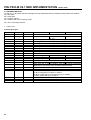
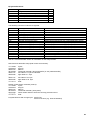
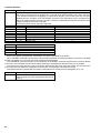
C) System Realtime
1111 1000
MIDI timing clock
Note: The timing clock is for the arpeggiator. The arpeggiator trigger is generated by dividing the
midi clock by the required clock division ratio. The midi clock divider operates even when midi sync
is not enabled, allowing the arpeggiator to synchronize properly even if midi sync has not been
enabled since the reception of the last START command. The midi timing clock is recognized for
midi clock divider counting purposes only after a START or CONTINUE command. Midi clocks after
a STOP command will not be recognized.
The following clock division ratios are employed:
Ratio
Arpeggiator step length
Clock division parameter
2
32nd note triplet
1
3
32nd note
2
4
16th note triplet
3
6
16th note
4
8
8th note triplet
5
12
8th note
6
16
quarter note triplet
7
24
quarter note
8
1111 1010
START command
1111 1011
CONTINUE command
1111 1100
STOP command
Note: The operation of the START, CONTINUE, and STOP commands is as follows:
When a START command is received the internal midi clock divider is reset and enabled. If midi sync is enabled
and the arpeggiator is on, the next midi clock will trigger the arpeggiator.
The CONTINUE command functions in the same way as the START command except that the midi clock divider
is not reset. Thus it enables the midi clock divider allowing the arpeggiator to operate if midi sync is enabled.
The STOP command halts the midi clock divider. Subsequent midi clock bytes will neither be counted by the
midi clock divider nor trigger the arpeggiator until a START or CONTINUE command is received.
Note that the START, CONTINUE, and STOP commands do not actually turn the arpeggiator on or off!
1111 1110
26
Active sensing
Note: If active sensing is not repeated within
300ms of being received, the Polysix-M will turn all
notes off.
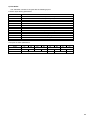
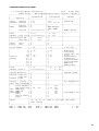
3) MIDI IMPLEMENTATION CHART
[ 6 voice polyphonic synthesizer ]
Date : 18.Mar.2000
Model PS-6M
MIDI Implementation Chart Version : RW/JH2.1
+----------------------------------------------------------------------+
|
| Transmitted
|
Recognized
|
Remarks
|
|
Function ... |
|
|
|
|-------------------+----------------+----------------+----------------|
|Basic
Default
| 1-16
| 1-16
| memorized
|
|Channel Changed
| 1-16
| 1-16, all ch
|
|
|-------------------+----------------+----------------+----------------|
|
Default
| x
| 3
|
|
|Mode
Messages | x
| OMNI ON/OFF,
|
|
|
|
| POLY, MONO
|
|
|
Altered
| ************** | x
| MONO ignored
|
|-------------------+----------------+----------------+----------------|
|Note
| 36-96
| 0 - 127
| *
|
|Number | True voice| ************** | 21 - 108
|
|
|-------------------+----------------+----------------+----------------|
|Velocity Note ON
| x
v=64
| x
|
|
|
Note OFF | x
v=0
| x
|
|
|-------------------+----------------+----------------+----------------|
|After
Key’s
| x
| x
|
|
|Touch
Ch’s
| x
| x
|
|
|-------------------+----------------+----------------+----------------|
|Pitch Bender
| o (B)
| o (B)
| 8 bit reso
|
|-------------------+----------------+----------------+----------------|
|
1 | o (B)
| o (B)
| Modulation
|
|
6 | x
| o
| Data Entry
|
|
7 | x
| o
| Volume 4bit res|
|
64 | o (D)
| o (D)
| Hold
|
|Control
70 | o (D)
| o (D)
| Chord Memory
|
|Change
71 | x
| o
| Arpeggiator
|
|
96 | x
| o
| Data Increment |
|
97 | x
| o
| Data Decrement |
|
98 | x
| o
| NRPN Fine
|
|
99 | x
| o
| NRPN Coarse
|
|-------------------+----------------+----------------+----------------|
|Prog
| o (C)
| o (C) 0 - 127 |
|
|Change | True #
| ************** |
0 - 127 |
|
|-------------------+----------------+----------------+----------------|
|System Exclusive
| o
| o
| Pgm/edit dump |
|-------------------+----------------+----------------+----------------|
|System | Song Pos | x
| x
|
|
|
| Song Sel | x
| x
|
|
|Common | Tune
| x
| x
|
|
|-------------------+----------------+----------------+----------------|
|System
|Clock
| x
| o
| for arpeggiator|
|Real Time |Commands| x
| o
|
|
|-------------------+----------------+----------------+----------------|
|
|Local ON/OFF | x
| o
122
|
|
|
|All Notes OFF| o (A) 123
| o (A) 123
|
|
|Aux |OMNI OFF
| x
| o
124
|
|
|Mes- |OMNI ON
| x
| o
125
|
|
|sages|MONO
| x
| o
126
| only MONO-1 rec|
|
|POLY
| x
| o
127
|
|
|
|Active Sense | o
| o
|
|
|
|Reset
| x
| x
|
|
|-------------------+----------------+----------------+----------------|
|Notes
| (A),(B),(C),(D) refer to the input and output
|
|
| midi filters.
|
|
|
|
+----------------------------------------------------------------------+
Mode 1 : OMNI ON, POLY
Mode 2 : OMNI ON, MONO
o : Yes
Mode 3 : OMNI OFF, POLY
Mode 4 : OMNI OFF, MONO
x : No
27
Revision History
1) CREDITS
I want to thank Ricard Wolf from Sweden for doing excellent work in both hardware and software and making the
results available for others.
2) REVISIONS
30.Oct.1999 Firmware:
Hardware:
RW1.1
PS6M.0A
10.Sep.1989
17.Oct.1999.
25.May 2000 PolySixM ROM
RW/JH V2.1: 18-Mar-2000
- MIDI control over single parameters
- Reception of MIDI controller
#$07 (Volume)
#$06 (Data Entry)
#$60 (Data Increment)
#$61 (Data Decrement)
#$62 (NRPN Fine)
#$63 (NRPN Coarse)
- Works with PolySixM editor P6.EXE V1.1
PolySixM editor
P6.EXE V1.1: 18-Mar-2000:
- First revision.
- Needs PolySixM ROM revision RW/JH V2.1
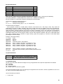
3) MISCELLANEOUS
There are future enhancements planned; such as: keyboard split, key window function, memorized key assign
mode.
If anything is unclear to you or you encounter any difficulties with modifications or have any questions or
suggestions, please let me know:
My email address is:
[email protected]
28