1
peterson
SINGLE BOARD DUO SET (SBDS)
COMBINATION ACTION
INSTALLATION AND SERVICE MANUAL
Revised 11/11/2011 (for Rev. F boards)
GENERAL INFORMATION
BRIEF
The SBDS combination action was designed to provide a complete combination action system supporting
two and three manual organs.
Each SBDS will recall the registrations of up to 64 stops that have been set on as many as 24 Generals
on a two manual console and 32 Generals on a three manual console. Two manual applications also
permit 16 Swell divisionals, 16 Great divisionals and 8 Pedal divisionals. Three manual applications
permit 8 Swell divisionals, 8 Great divisionals, 8 Choir and 8 Pedal divisionals, each with 128 memory
levels.
Other features of the SBDS include four Reversibles, Pedal Piston Couplers for each manual, and a
Piston Sequencer to step through general pistons.
MEMORIES
The SBDS has 128 memory levels that are rotary knob selected via a Mini Control Panel that has a seven
segment display to indicate the current memory level. The SBDS may be operated without the Mini Panel
if only one memory level is desired.
The memory used on the SBDS is a non-volatile EEPROM that requires no battery, capacitor module, or
any other kind of back up power.
STOP SENSING
The SBDS accepts either positive or negative sensing inputs, field selectable, by simply changing the
position of one programming jumper plug. The sense inputs are arranged in a row of connector pins
which are compatible with all of Peterson’s familiar plug-on connector types. These rows are organized in
groups of 8 stops each with 8 groups for regular stops and a separate group for the reversibles.
NOTE: If more than 64 stops or 3 divisions are required, two SBDS systems may be used together.
STOP MAGNET OUTPUTS
Stop magnet (coil) outputs are arranged in separate rows for the ON coils and the OFF coils. These rows
are organized in groups of 8 stops each with 8 groups for regular stops and a separate group for the
reversible coils.
Each output is capable of driving 900mA (15 Ohms @ 13.8VDC or 20 Ohms at 18VDC) with an 18V
recommended maximum.
The standard coil common is negative. An alternate version of the SBDS is available should a positive
common be required.
PISTONS
The SBDS accepts either positive or negative piston inputs, field selectable by simply changing the
position of one programming jumper plug. A total of 64 settable pistons per SBDS are supported. These
64 pistons are assigned differently depending on whether the SBDS is used in a 2 manual or 3 manual
organ.
The sense inputs are arranged in a row of connectors. The row is divided into groups of 8 stops per group
with 8 groups for regular stops and a separate group for the reversibles.
1
The assignment of the pistons is:
2 Manual -- 24 General, 16 Swell, 16 Great and 8 Pedal (+4 Reversers).
3 Manual -- 32 General, 8 Swell, 8 Great and 8 Pedal (+4 Reversers).
There are also some miscellaneous piston inputs that include: Set, General Cancel, Piston Sequencer
Next and Previous, Memory Up and Memory Down. These are not affected by the selection of 2 or 3
manuals.
SET MODES
Stop registrations can be “set” or “captured” in two different ways (thus the proprietary product name “Duo
Set”).
1. Capture Method: When stops are registered as desired, press and hold the Set piston, then press the
numbered piston that the registration is to be recalled from. Release the numbered piston and then
release the Set piston, in that order. The desired registration will be “captured” on that piston.
2. Tripper Method: Press and hold a numbered piston and add or subtract stops as desired. A numbered
piston held for approximately one second will automatically be put in the set mode.
Some organ builders have used “capture” systems and others “tripper” systems. The Peterson Duo Set is
comfortable for organists trained on either.
POWER REQUIREMENTS
The SBDS is completely powered by the organ power supply (rectifier). An SBDS that has all 64 stops
energized may draw close to 50 Amps during the time the coils are energized.
The organ power supply (rectifier) Voltage required is 10.5V Minimum to 18V maximum and must have
adequate filtering and regulation. At no time, even for a brief instant, should the Voltage drop below 9V or
exceed 24V. Voltage below 9V may cause erratic behavior. Voltages exceeding 24V may damage
components.
To help the organ builder identify rectifiers that are not adequately regulated, Peterson includes a Power
Supply Fault Detector on systems that we mount and wire. This Fault Detector is otherwise optionally
available. The Fault Detector indicates “out of range” for high level and low level Voltages via latched
LED indicators.
NOTE: Organ indicators that flash and dim when pistons are pressed typically indicate an inadequate
rectifier. See Peterson’s “IMPORTANT PRECAUTIONS” and “ORGAN POWER SUPPLY AND
FEEDWIRE SIZE WORKSHEET” for more information. We recommend replacing questionable older
organ rectifiers with Peterson Inteli-Power® switch mode power supplies.
SAFETY PROCEDURES AND CAUTIONS
1. NEVER apply power to the system during installation. All wiring must be completed and
thoroughly checked. Then follow the “Initial Test” procedure before applying any power.
2. Organ rectifiers supply Voltages and currents similar to arc welders. Due to these high currents it
is highly recommended that the organ power be turned off whenever the system is being worked
on.
3. If it is necessary to work on the system while the power is on, for your own personal safety we
recommend removing jewelry, such as watches, rings or pendants before work is attempted.
Jewelry that shorts across the organ supply will heat up rapidly and may cause severe burns.
Electronic components can also be damaged.
4. Do not lay tools, wire, solder, hardware or any other conducting material on the system’s printed
wiring boards, connectors or cables with the power on or off.
5. Should any conducting item such as tools or hardware fall on or near the system, turn the power
off immediately. Then remove the item. Do not assume hardware has fallen clear: find it.
6. If you detect any defects in the cabling or circuit boards, such as burned insulation or melted foils,
it is imperative that you check for and find any shorts within the system or its wiring. Merely fixing
the obvious could result in further damage. Call us at 800-341-3311 if in doubt.
2
Peterson now offers custom-made wiring harnesses to connect the “on” and “off” coil and “sense” lines of
the combination action to the connectors that plug onto Peterson PowerTab™, PowerKnob™, ZBracket™, and T-Rail™ stop control units and assemblies, as well as some other brands. Peterson will
also mount all combination action components to a wood panel and wire all lock-out and power
connections between SBDS Assemblies and to junctions if you desire. A cabled and mounted
combination action from Peterson is supplied with all of the appropriate fusing, wire sizes and
other considerations necessary for compliance with the National Electric Code (NEC ).
INSTALLATION INSTRUCTIONS
1. Carefully unpack all cartons and check for damage that may have resulted from shipping.
2. Select a suitable location for the SBDS board(s) bearing in mind ease of access for wiring and
servicing. Orient the SBDS board(s) so the Mini (Control) Panel ribbon cable is closest to where
the Mini Panel will be mounted to keep this cable as short as possible. Also if more than one
SBDS is used in the same console, arrange the SBDS boards so the ribbon cable that connects
them is as short as possible. The Mini Panel cable should be kept to less than 8’ if possible and
the Primary/Secondary) (formerly Master/Slave) cable to less than 3’. It is preferred that these
ribbon cables be routed differently or separately from the On/Off coil wiring. Never bundle the
ribbon tightly together with coil wiring.
3. Mount the SBDS boards using 20 screws (supplied) for each SBDS system. Be sure to allow
sufficient space around these boards to allow for neat cabling along each side. Provide a loop in
all cables to allow easy removal of connectors.
A note about circuit labeling: Both the piston and stop circuits (sense, on and off) may have two labels
used for two and three manual systems. The first label refers to pin assignments for a two manual
system. A label in parenthesis is used for a three manual system. Stop circuits 57-64 labeled “GEN1 –
GEN8” are for couplers or other stops that are only to be affected by general pistons.
4. Cable the “on” and “off” coils and “sense” contacts to their respective terminals, as indicated in
Fig. 1. NOTE: When very long cables are going to be used, such as for a remotely mounted
CA, we highly recommend that the “on” and “off” coil wire cabling be bundled separately
from the “sense” and piston wire cabling. Do not run the wires of these two categories
together since this has been found to occasionally cause problems under certain
circumstances. The “sense” contact is usually the same contact that is used to operate the relay
or a stop action in the organ; this is the simplest and preferred arrangement. If this “sense”
contact is connected to a magnet, it is necessary that a “flyback” (spark suppression) diode be
connected across the magnet to protect the combination action. The polarity of the diode is
important. To determine polarity, operate the magnet involved and measure the Voltage across it,
noting which is the positive end. Always connect the cathode (banded end) of the diode to the
positive end of the magnet. Sense input protection circuit boards are available from Peterson.
These include flyback diodes for each sense input and plug onto the SBDS board(s). Flyback
diodes for the “on” and “off” coils are built into the output of the SBDS boards. Each stop magnet
of each division should be assigned a number, in some logical manner (from left to right, for
example). It would be a good idea to list the stop assignment on the form supplied (Fig. 3). For
future reference. Each position’s “on”, “off” and “sense” pins must all be connected to the
same stop action magnet.
Stops can be controlled from more than one set of SBDS circuits. For example, it might be
desired that the Swell to Pedal coupler be wired to work from a reversible. In this case simply wire
the Swell to Pedal stop action’s “on”, “off” and “sense” to both a regular position on the SBDS and
to a reversible (located on the end beyond stop circuit #64).
“Unison Off” stops must use a sense contact that is the same polarity as all other stops when
connected to the SBDS. (In some cases, with non-solid state relays, organs may have had
contacts that were closed when the unison is “off”).
If stop sensing polarity is not positive, simply move the Sense Polarity selector “jumper plug” from
“+” to “-“. Note that Crescendo and Tutti lockout polarities will follow the selected “sense” polarity.
3
5. Cable the piston contacts to their terminals in the piston input row of connectors on the SBDS.
(See Fig. 1.)
a. Wire piston commons, for their respective polarity, to the designated “+ PIST COM” or “PIST COM” connector pin located at the end of the SBDS piston connector row. These
piston common terminals are fuse protected (with resettable fuses) and are the preferred
feed point for piston commons. All pistons can be fed from one terminal.
b. Wire the Set piston, if any, to the “Set” terminal located at the end of the SBDS piston
connector row. This uses the same piston common as the other pistons.
c. Wire the General Cancel piston contact to the “Gen Can” terminal located at the end of
the SBDS piston connector row. This uses the same piston common as the other pistons.
d. Wire “general” pistons to their designated terminals located on the SBDS piston
connector row, sequentially starting with #1. There’s a maximum of 24 generals available
for a two manual configuration and a maximum of 32 generals available for a three
manual configuration.
e. Wire “divisional” pistons to their designated terminals located on the SBDS piston
connector row, sequentially starting with the first one of a given division. There’s a
maximum of 16 Swell pistons, 16 Great pistons and 8 Pedal pistons available for a two
manual configuration and a maximum of 8 Swell pistons, 8 Great pistons, 8 Choir pistons
and 8 Pedal pistons available for a three manual configuration.
NOTE: The labeling on the SBDS board for pistons shows an abbreviation for the two manual
configuration followed by an abbreviation for the three manual configuration in parentheses.
Example: GT9 (CH1).
6. If a multi-contact sforzando/ tutti switch is used, wire one contact to the “Tutti” screw terminal of
the “Lock Outs” (plug in) barrier terminal (CN3) located beyond the end of the SBDS piston
connector row. (See Fig. 1.) This terminal or contact may be shared with an indicator, but not a
stop. If a Peterson solid-state Sforzando Reversible is employed, wire the Sforzando Output
Terminal on the reversible to the “Tutti” screw terminal of the “Lock Outs” (plug in) barrier
terminal.
7. Wire the first contact to “make” on the crescendo switch (roller, etc.) to the “Cresc” screw terminal
of the “Lock Outs” (plug in) barrier terminal (CN3) located beyond the end of the SBDS piston
connector row. (See Fig. 1.) This terminal or contact should be shared with the Crescendo
indicator, but not a stop.
8. If you desire key locks, to prevent setting of all or some memory levels, wire one terminal of a
single pole (SPST) switch to the desired lock-out terminal of the “Lock Outs” (plug in) barrier
terminal (CN3) located beyond the end of the SBDS piston connector row. (See Fig. 1.) The other
contact of this switch connects to the “Key Com” terminal (#5). With the contacts of this switch
closed, the combination action cannot be “set”, therefore making it “tamper-proof”.
For a “Master Lock-out” connect terminals 1-4 to the same switch. Alternately, memory levels 132, 33-64, 65-96 and 97-128 (terminals 1-4 respectively) may be locked separately using
individual switches. Other possibilities would be to “lock” one or more of these groups with a
single key. Thus, the main organist can protect their combinations while leaving some memory
levels available for other organists or guests.
The following key operated switches available from Peterson are:
Part Number
140612
400648
Description
Key operated switch (only)
Lock out key switch with nameplate
Please specify white or black plastic or solid brass engraved nameplate. (See Figure 4 for
mounting details.)
NOTE: Many times problems with stops not setting, combinations forgetting, or previously set
combinations changing themselves are not the fault of the combination action. These symptoms can be
caused by sluggish drawknobs or stop keys or by dirty, corroded, or open stop switch contacts.
4
Mechanically sluggish knobs or tabs may not move to their proper setting in the time the combination
action energizes their coils. If the piston is held (approximately) one second longer than the coils are
energized, the combination action will go into the “tripper” mode and any stops not having moved to their
intended position, or any contacts not properly open or closed, will cause a new but wrong combination to
be set into the memory.
Dirty or corroded contacts become resistive and essentially put a resistor in series with the stop wire from
the feed. Although this resistance is usually quite low, it forms a Voltage divider. There may be enough
Voltage to energize the stop magnet, but not enough to address the memory properly. This Voltage drop
should not exceed 5 Volts across the stop contacts. This Voltage can be measured with a Voltmeter
connected across the contacts.
Open contacts will not address the memory at all. Some organs have separate contacts for the
combination action “sense” and for the actual stop switch. With this arrangement it is possible for the stop
to work but the combination action to not be “addressed”. For this reason it is preferred to use only one
contact for both the sense and stop switching. Or better yet, connect both contacts in parallel.
It is important to be sure the stop controls and their contacts are in good working condition to properly
address the combination action. Do not assume the contacts are “making” because they appear to be
touching. (Any contact in question can be confirmed by measuring with a Voltmeter.)
Problems associated with sluggish knobs and tabs setting improperly in the tripper mode, can be
minimized by wiring a Master Lockout Switch as in step 8 above. The Master Lockout will defeat the set
mode, thus preventing re-setting. A much better answer however is to see that the knobs and tabs are
properly adjusted and supplied with adequate power.
NOTE: In the case of sluggish (binding) stop actions, the length of time the coils are energized
can be increased to aid moving them properly by adjusting the “Coil On Time”. There are 3
positions on DIP switch “S2” that determine the coil on time. A chart printed on the circuit board shows
the settings of these DIP switches for times ranging from 100mS (1/10 second) to 450mS (almost ½
second), in 50mS increments. It is advised that the shortest possible time be used that allows all the stop
actions to move properly. (Longer time settings also cause a slower response when changing pistons
quickly.)
9. Connect organ positive (+) and negative (-) from the organ power supply (rectifier) to their
respective screw terminals (CN4) on the SBDS board(s) labeled “- ORG +”. Bear in mind that
the positive (or coil feed polarity) lead must be of sufficient size to carry the feed current
to all the stop magnets simultaneously! Likewise, the negative (or coil return polarity) lead
must be of sufficient size to carry the return current of all the stop magnets
simultaneously! (See the “Organ Power Supply (Rectifier) and feed wire Size Worksheet”.)
It is a good practice to run one wire of adequate size from place to place rather than to run two
smaller conductors in parallel, unless the smaller conductors are of identical lengths and follow
identical paths. Check polarities carefully before applying power to the system. Reversed
polarities may cause damage to the equipment. Warranty does not cover this kind of damage.
If one organ power supply (rectifier) of adequate size is not available, two or more can be used in
the installation. One of the following wiring schemes should be chosen, based on the type of
power supply, power supply locations, existing wiring, and overall system requirements.
Power supply (rectifier) designs that use selenium diodes, or use "choke" filters (and some solid
state regulator types) should not be paralleled. The ferro-resonant transformer type and some
others can be paralleled. Paralleled rectifiers should be set so they provide the same Voltage
output. In other cases one rectifier can be used to power the relay chamber and chests, and the
other for the stop knobs or tabs. Ideally, the stop action magnet ("SAM") supply should be in or as
near the console as possible to reduce the Voltage drops in the feed wires. Connect a common
negative between rectifiers and to the organ negative screw terminal on each SBDS board. A #16
wire can be used. Connect the "SAM" supply positive to the SBDS screw terminal (marked ORG
+.) on the SBDS board(s). This positive feed wire must be of sufficient size to handle the feed
current of all the stop action magnets. (See the “Organ Power Supply (Rectifier) and feed wire
Size Worksheet”.)
5
With separate rectifiers connected in this way, and when a Peterson solid state switching system
is used, the SAM supply output Voltage can be set 1 V to 2V higher than the organ supply
Voltage to provide a "snappier" action. (Setting the Voltages different when used with an electropneumatic or electro-mechanical relay may cause problems with false settings or improper
reversibles operation).
The correct way to connect Peterson’s Inteli-Power® supplies in parallel is to mount them as
close together as possible and use the shortest possible #6-8 wires of equal length to parallel
them. Then the negative supply wire should be connected to one of the Inteli Power units and the
positive supply should be connected to the other unit.
If there is any question as to whether your particular rectifiers can be paralleled or wired as
described above, please call Peterson at 1-800-341-3311 and ask for advice.
10. REVERSIBLES. Each Peterson SBDS provides four independent reversible circuits to support
four separate reversible stops. Systems requiring two or more SBDS boards add four reversibles
per board. Refer to Figure 1 for details of terminal assignments.
Wire the Reversible "on" and "off" outputs to their respective stop’s "on" and "off" outputs for the
stop(s) to be reversed.
Wire the terminal(s) for the Reversible "sense" to the "sense" terminal for the stop(s) to be
reversed.
In most cases the “sense”, “on” and “off” wires for stops to be reversed actually parallel other
stops previously wired in other divisions.
Wire the piston input terminal(s) of the Reversible(s) to their respective pistons. The reversible
pistons must be fed by the same polarity used for other pistons.
Note that there is one "on" coil terminal and three "off" coil terminals for each reversible. This
allows for a situation as in this example: Swell to Pedal 8' work as a full reversible. The Swell to
Pedal 16' and Swell to Pedal 4' can be made to cancel if they are "on" by simply wiring the other
off coil terminals to the "off" coil on the Swell to Pedal 16' and Swell to Pedal 4' stop actions.
11. Sforzando reversibles are separate from the above reversibles. Install a #400365 sforzando
type reversible (if purchased), with screws supplied. Connect power, pistons, etc., to terminals as
labeled on the sforzando reversible assembly. The piston must be fed from organ positive (+).
The sforzando (or "tutti") piston will cause an output to appear at the "sforzando output" on
alternate pressings. The sforzando reversible is "self holding." Therefore the output will continue
to be present indefinitely with only a momentary signal at the sforzando piston terminal.
Sforzando output can be removed by:
a. Re-pressing the sforzando reversible piston.
b. Pressing a cancel piston (usually general cancel if connected to the cancel piston
terminal on the sforzando reversible).
c. Turning the organ off for a short period of time. When the organ is turned on the
sforzando will automatically stay off. The only way to turn it on is with a momentary organ
positive (+) applied to the sforzando piston terminal (as by pressing the sforzando
piston).
12. MINI (CONTROL) PANEL - The Peterson SBDS has 128 memory levels that can be addressed
by the Mini Panel (See Fig. 2.). Select a convenient location on the name board, side jambs or
key desk to mount the Mini Panel. Use the template of Fig. 2 to make the cutout. Remove the
long “U” bracket (used to clamp the panel in place).
Insert the ribbon cables for the Mini Panel through the cut-out and plug one end of the ribbon
cables with CN1 to the outside connector and CN2 to the inside connector with pin 1 for both
towards the top. The other end of the ribbon cable must be plugged onto the SBDS’s connectors
CN1 & CN2.
6
Remove the backing from the double- sided adhesive tape on the back surface of the front panel.
Carefully insert the Mini Panel into the cutout, align it as desired and press into place. Then reinstall the “U” bracket from the back side and using the provided hardware, tighten to firmly hold
the Mini Panel in place.
Note: The “U” bracket has double nuts to hold it at the proper height to match your name board
thickness. Adjust both so that the “U” bracket is firmly holding the Mini Panel to the name board.
Then install the provided sheet metal screws to hold the bracket to the name board.
13. PRIMARY/SECONDARY (formerly Master/Slave) - If the total number of stop tabs of any division
is greater than the capacity of the SBDS, a second SBDS board can be used to expand the
number of stops and/or divisions. If this is the case, mount both SBDS boards keeping in mind
that the one that will have the Mini Panel connected to it will be the “Primary”. The “Secondary”
SBDS must have its “Prim/Sec” jumper (JP19) moved to the “Sec” position. Plug a supplied 10
pin ribbon cable onto CN6 of both SBDS boards observing the polarity of pin 1. (This
Primary/Secondary ribbon cable connects the memory level address lines of the two boards
together so they both track the Mini Panel display.)
Piston wiring for generals, set, cancel, next, previous and any divisionals that are shared by the
two boards need to be jumpered (paralleled) from the Primary board to the Secondary board.
Also, the lockout terminals need to be tied together.
Alternately, if more pistons are required, the stop sense, on and off wiring can be paralleled on
two SBDS’s thus allowing twice the piston inputs. In this case only the set, cancel, next, previous
and lockouts are tied together.
SBDS SYSTEM CONFIGURATION
Since the SBDS was designed to be a flexible combination action system suitable for two and three
manual organs, there are a number of configuration options that must be set prior to use.
Piston Polarity – “Program jumper” JP9 selects positive (positive feed) or negative (negative feed)
pistons. Position this “program plug” for the desired polarity. Default is positive.
Sense Polarity – “Program jumper” JS9 selects positive sense (positive feed) stops or negative sense
(negative feed) stops. Position this “program plug” for the desired polarity. Default is positive.
2 or 3 Manual Option – There is a “program jumper” selection option, JM3, located near the center of the
board (between the Organ +/- connection and the Lockouts barrier). Position this program plug for the
desired organ size to be used.
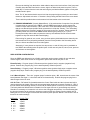
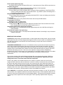
Coil On Time – DIP switch S2 (located between the Control Panel cable and the Lockouts terminal) is
used to determine the length of time coils are energized when pistons are pressed. Positions 2, 3 & 4 of
this DIP switch allow selecting 100mS (1/10 second) to 450mS (almost ½ second) in 50 mS increments.
The factory default is 200mS which is suitable for most organ with new or good working stop actions.
Should it be necessary to increase the coil on time due to sluggish stop actions, it is recommended that
the time be increased to the minimum necessary to make all the stop actions function reliably. NOTE:
Making the coil on time longer increases the time between piston presses. Below is a chart of the coil on
times for the various settings.
DIP Switch
2 3 4
0 0 0
1 0 0
0 1 0
1 1 0
0 0 1
1 0 1
Coil On Time
150mS
200mS
250mS
300mS
350mS
400mS
7
1 1 0
1 1 1
450mS
500mS
Pnematic/Elecric Mode – DIP switch S2 (same as above) position 1 selects Pneumatic mode (only coils
that need to change are energized) or Electric mode (all coils always energize). The pneumatic mode has
the advantage of quieter operation and less current consumption. The electric mode provides a constant
load and coils will always respond with the same ‘intensity’. Pneumatic mode is selected by turning switch
1 on.
Static Pedal Piston Couplers (PPCs) – In some installations it may be desired to always have the pedal
pistons operate with the manual pistons. If this is the case, DIP switch S1 (located near the heatsink)
positions 1, 2 & 3 can be used to achieve this. Position 1 is for the Swell, position 2 for the Great and
position 3 for the Choir (if 3 manual). Turn the desired PPC on by moving the DIP switch away from the
edge of the board. NOTE: The PPCs are available on stop inputs (connector JR1) and may be operated
via stops or wired to reversibles, cheek switches and the like. However, if the static PPCs are on, the
stops will be over-riden.
Maximum Generals – If the Piston Sequencer is to be used, the actual maximum number of generals
must be set. (This determines the wrap point.) This is accomplished on DIP switch S1 using positions 4-8.
These are labeled 1+2+4+8+16. Set the sum of these switches to equal the actual number of generals
used –1. For example, if there are only 8 generals subtract 1 = 7. Set the switches to total 7, 1+2+4 =7.
For 10 generals it would be (9), 1+8 = 9. (The reason for –1 is because with no switched on (zero) it
works for 1 general.)
Last General Pressed Read Out Option – If the piston sequencer is to be used, it may be desirable to
have an indication of what general piston the sequencer is currently on. This optional plug-in (via ribbon
cable) board provides both a two digit seven segment display (1-32) and individual indicator outputs that
can be used for lighted pistons. Wiring details will be provided with this option.
PRIMARY/SECONDARY (formerly Master/Slave) – If two SBDS systems are required for larger
instruments, this feature allows one Mini (control) Panel to select the memory level for both boards. The
SBDS with the Mini Panel connected to it will be the Primary. The other one thus becomes the
Secondary. Be sure to change the “program jumper” for the second one to “SEC” and connect a 10 pin
ribbon cable between the two SBDS boards. The “PRIM/SEC” option is located between the Coil On Time
DIP switch and the 2-3 Manual selector.
Feed Polarity and Return Polarity – NOTE: The wire jumpers that select the coil output polarity are
factory ONLY selections. The default (standard) is for positive feed and negative return. Should you
require coils drivers with the opposite polarity, you must order a special SBDS from the factory configured
this way. (Different driver ICs are required as well.)
Also note connectors CN7 BDM and CN5 JTAG are used for factory programming and testing. Do not
connect anything to these connectors.
TEST PROCEDURE FOR THE PETERSON SBDS COMBINATION ACTION
Before testing the combination action electronics, the stop action units should be tested for proper
operation and wiring. For the standard default polarities, unplug the on-off coils from the SBDS, turn on
the organ power and use a test lead from organ positive to key each magnet at the connector pins (now
unplugged). Be sure each stop unit moves to the proper position, on and off, when keyed from its
designated pin (see Fig. 1). Sense contacts can be tested by measuring with a Voltmeter. Connect the
meter's negative lead to organ negative. Organ rectifier Voltage should be measured at the sense
terminal when the stop is on. Once all stop units have been tested, turn off the power and plug the
connectors back onto the SBDS board(s). Be sure the pins line up correctly. Test the combination action
electronics in the following way:
NOTE: Several conditions can result in damage to the equipment, as described below. Should such
conditions develop, determine the cause of the problem as quickly as possible.
8
SMOKE OR BURNING SMELL (Serious damage is likely to result or has already been done). Turn off
the organ power promptly before pinpointing the source.
STOP ACTIONS HUNG "OFF" OR "ON" (One or both coils energized). This may cause the coil or
output driver to overheat and be damaged. This type of damage can happen quickly. It is important to
check for this condition upon initial powerup and remove power if it occurs.
PRELIMINARY TESTS
1. With power off, use an Ohm meter to measure across the +/- ORG terminals CN4 to be sure
there is not a direct short. The reading will vary depending upon the type of organ rectifier used,
but in all cases you should expect a relatively low resistance (tens of Ohms to hundreds of Ohms)
that increases over time. (This increase in resistance is caused by the charging of capacitors.) If a
reading of less than one Ohm is observed, it is an indication of a short circuit. Go to the
troubleshooting section.
2. Connect a Voltmeter across capacitor C33 (see Fig. 1), with your meter leads in the polarity
shown.
3. Turn the organ on. A reading of 5.0 Volts (DC) +/- ½ Volt should be observed. If not, turn power
off and proceed to the troubleshooting section.
4. Connect a Voltmeter to read the organ rectifier Voltage at the organ + and organ - terminals. You
should read 10.5V-18VDC. Then press the general cancel button several times in rapid
succession and observe the Voltage reading. If it drops below 8.5VDC refer to the "ORGAN
POWER SUPPLY AND FEEDWIRE SIZE WORKSHEET (Page 16).
MAIN TEST
1. Turn the organ "on".
2. Check to see that all stop actions will stay in the on or off position when moved to either position.
3. If they "spring back" to one position or the other with the organ on, but not off, turn the organ
power off and refer to the troubleshooting section before proceeding.
4. Manually turn all stops on.
5. With all stops on, press general cancel. All stops should turn off. If they do not, refer to the
troubleshooting section.
6. Set one piston for all stops on. Set as a capture action; select stops, press the "set" piston, select
and press the desired piston, release the piston, release the set piston.
7. Set a different general piston using the tripper (hold and set) method. To set as a tripper action,
simply press the piston, manipulate stops to the desired combination, release the piston.
Remember that it takes about one second after the piston is pressed before the system
automatically goes into the "set" mode. When in the set mode, a yellow light labeled "LED17" on
the SBDS board(s) should be illuminated in a blinking fashion and the “+” sign on the Mini Panel
should be blinking.
NOTE: If the combination action will not set, check to be sure the crescendo, sforzando, and/or
"Lock-out" are not activated, and that any crescendo and/or sforzando indicator bulbs are wired
with their return to the proper polarity.
8. Set the divisional pistons in some easily recognizable sequence. For example: Piston 1, stops 1
and 2 on, and all others, off. Press pistons to make sure they do what they were set to do. If they
do not, refer to the troubleshooting section before proceeding.
9. Set general pistons to some easily recognizable sequence. For example: Piston 1, stops 1, 2 and
3 on, all others off. Piston 2, stops 4, 5 and 6 on, all others off. Press pistons to make sure they
do what they were set to do. If they do not, refer to the troubleshooting section before proceeding.
END OF TEST
9
TROUBLESHOOTING SECTION
Troubleshooting the Peterson SBDS Combination Action is easily accomplished once a few basic things
are understood. Be sure you read this Troubleshooting Guide in its entirety before attempting any repairs.
WARNING
There are "CMOS" I.C.s (integrated circuits) used throughout the SBDS circuitry.
"CMOS" I.C.s can be damaged by Electro-Static Discharge (ESD)!
There are protection circuits designed into these boards to prevent "ESD" damage in their normal
operating conditions. Some caution should be used to prevent "ESD" damage to modules that are being
removed or replaced while servicing.
Before working on or near the SBDS board or its cabling:
1. Always turn organ power off
2. Put on the provided ESD wrist band with its other end attached to organ negative. If the wrist band is
not available, touch a finger to organ negative to discharge any static charge. This should be done each
time you return to the SBDS after stepping away.
If boards are removed...
1. Do not touch the backs of the boards where there are I.C.s, and don't touch the connector pins when
handling. Place removed boards in anti-static bags provided.
Returning defective modules
1. Handle as above
2. Wrap the boards in aluminum foil or re-use the pink conductive foam or black anti-static bags from the
original shipping material for packing.
ALWAYS TURN THE ORGAN "OFF" WHEN REMOVING AND REPLACING BOARDS!
A short circuit in a stop action magnet or its associated wiring can destroy an output driver IC or other
electronic component, so before changing driver ICs or boards, check the stop magnet coil resistance
and its wiring to avoid damaging the replacement parts.
A red LED next to any fuse that is illuminated indicates the fuse is blown (open). (All fuses will self reset;
once they cool off they will conduct again. These fuses are yellow in color and are thin, rectangular
devices with an F# label.)
WARRANTY DOES NOT COVER DAMAGE AS A RESULT OF CARELESSNESS OR ABUSE
Before speculating on problems, it is a good idea to check for proper operating Voltage. Refer to the
Preliminary Test steps 1-4 to check the organ and regulated 5 Volts. The lock out terminal should read
approximately zero Volts (with respect to Org -) unless the set function is to be locked out, in which case
the lock out terminal is connected to Org. +. The Org + and Org - (or SAM +/-) terminals are connected to
the power supply (rectifier) intended to move the knobs or tabs. This will usually be between 10.5 and 18
Volts depending on the knobs and tabs used. For the knobs and tabs to operate dependably, this power
supply must have adequate capacity and Voltage regulation. NOTE, however, that about 1.8 Volts will be
lost in the combination action so that the actual Voltage reaching the stop action magnet coil will be 1.8
Volts less than the power supply.
Stops on the SBDS are arranged in groups of 8 stop actions per group. There are 8 groups total to cover
the 64 stops. Each group of 8 stops has electronic components associated with the ‘sense’ and ‘driving’
(of on/off coils) for the 8 stops, included as a part of each of these groups. The chart shown in Figure 3
10
shows which stops go with which group. When installing the system it is a good idea to fill out this chart
and keep it with the system. Any fault that affects only a single stop, or cluster of stops that are all
associated with the same group, would suggest trying a different group. The ‘sense, ‘on’ and ‘off’
associated with a suspect group can be shifted to another group of stops that are working properly, and if
the suspect group is in fact defective, the symptoms will not move with the shifted connectors.
CAUTION: The heatsink for the 5V regulator will be HOT to the touch when the organ is on (similar to hot
tap water). Caution should be exercised when working in the area of the heatsink.
If a problem should occur after the installation is completed, the following guide should be helpful in
pinpointing the source of the trouble. Find the heading(s) that matches your problem and then follow the
steps (in the order listed) until the problem clears up or moves.
If a step asks to "swap" a connector or a board, TURN THE ORGAN POWER OFF. Then unplug the
suspected connector or board and replace it with a known good element.
Once the problem is pinpointed, if a replacement board is needed or if you need further assistance, give
us call at (708) 388-3311 or Toll Free (800) 341-3311.
NOTE: The following assumes positive pistons, positive sense and negative coil returns are being used. If
this is not the case, the same guides can be used keeping in mind the alternate polarity.
SBDS TROUBLESHOOTING GUIDE
MEMORY LEVEL PROBLEMS
1. LEVEL STAYS ON “1” WHEN ROTATING THE KNOB. Verify that the Primary/Secondary (formerly
Master/Slave) selector is set to Primary for the SBDS where the Mini Panel is attached.
2. LEVEL DISPLAY ON THE MINI PANEL IS BLANK. Nothing is displayed. Verify that connectors to
CN1 & CN2 are not reversed at one end or the other.
3. A SECOND SBDS DOES NOT TRACK THE FIRST ONE. Verify that the Primary/Secondary
(formerly Master/Slave) selector is set to Primary for the SBDS where the Mini Panel is attached and
to Secondary for the second board and that the 10 pin ribbon cable between the two boards is
properly aligned (pin 1 to pin 1).
PEDAL PISTON COUPLER (PPC) PROBLEM
1. PPC IS ALWAYS ON. Verify that the “Static PPC” DIP switches 1, 2 and/or 3 on S1 are not turned on
and that there is no voltage on the JR1 connector pins.
PISTON PROBLEMS
1.
PISTONS DO NOT APPEAR TO WORK
a. Verify that the Voltage applied from the pistons matches the piston polarity selected by
JP9.
b. Try touching a test lead from the desired polarity directly to the piston input connectors on
the SBDS. If this works there’s likely a problem with the piston common or other wiring.
c. Check that the “Set” light and/or “+” on the control panel is not on or flashing indicating a
“stuck piston” (system in “Set: mode).
d. Check F12 (30A) to be sure it’s not open.
2.
INTERMITTENTLY GET WRONG COMBINATION
a. Change to “Pneum” (pneumatic) mode by turning on switch #1 of DIP switch S2. If the
problem clears it is likely a power (Voltage) problem. See power worksheet.
b. Measure organ rectifier Voltage on the screw terminals of CN4 while repeatedly pressing
GC (Note: Turn off “Pneum” switch #1 on DIP switch S2.). If it is less than 10-11V, try
raising the Voltage (or see power worksheet).
11
c.
Increase the coil ON time by changing the settings of switches #2-4 on DIP switch S2.
This time will be set for 200 mS from the factory and it may be increased up to 450 mS.
3.
INTERMITTANTLY GET WRONG COMBINATION on 1 or 2 pistons (apparently shorted
together)
a. Unplug piston wiring and try with a test lead from Organ +. If O.K. check wiring for a short
between the two pistons.
4.
GEN CANCEL WON'T WORK
a. Use Voltmeter to measure cancel input with respect to organ negative. Should read
rectifier Voltage when cancel is pressed.
b. Check F12 (30A) to be sure it’s not open.
PISTON SEQUENCER (“PSQ”) PROBLEMS
1. ON A 2 MANUAL SET-UP THE PSQ WORKS SWELL DIVISIONALS after the last General. Verify
the “MAX GEN” DIP switch (S1) setting. (Subtract one from the actual number of Generals being
used. Then find the combination of the DIP switches 1+2+4+8+16 that equals the actual number
minus 1. Example: There are 16 actual General piston buttons. 16-1=15. 1+2+4+8=15. For 10
Generals (=9) use 1+8.
2. NOT ALL OF THE GENERALS ARE SEQUENCED. Verify the “MAX GEN” DIP switch setting.
(Subtract one from the actual number of Generals being used. Then find the combination of the DIP
switches 1+2+4+8+16 that equals the actual minus 1. Example: There are 16 actual General piston
buttons. 16-1=15. 1+2+4+8=15. For 10 Generals (=9) use 1+8.
3. THE PSQ DOES NOT WORK. No pistons are sequenced. Verify that the “MAX GEN” DIP switches
are not all off. (With all switches off the sequence length is one piston.)
SETTING PROBLEMS
1. NO STOPS WILL SET ON ANY PISTON; General or Divisional (but stops do move when pistons
are pressed).
a. Be sure Cresc, Tutti and Key Locks are not active (Any Lock LED on Main board lighted).
b. Temporarily disconnect all Crescendo, Sforz. and Lockout wires and try setting.
c. Verify stops polarity. Measure the Voltage on the sense inputs for stops that are
on. If it reads positive, be sure the “Sense” jumper (JS9) is set to positive as well.
2. CHOIR DIVISION WON’T SET or affects the Great. Verify that the “2-3 Manual” select jumper
(JM3) is set to 3 manual.
3. ONE STOP WON’T SET ON (but is affected by GC).
a. Use a test lead from Organ + to energize the on coil output at the SBDS output
connector. If ‘dead’ then there’s a wiring or stop action problem.
b. Verify that the “Any Stop” LED13 lights when this (and only this) stop is energized. If not,
then there’s a wiring or stop action problem. Sense Voltage must be greater than 3.5V
when the stop is on.
c. Suspect a bad UDN2982 driver for that stop.
4. ONE STOP WON’T SET OFF.
a. Use a test lead from Organ + to energize the Off coil output at the SBDS output
connector. If ‘dead’ then there’s a wiring or stop action problem.
b. Verify that the “Any Stop” LED13 goes off when all stops are off. If not, then there could
be a wiring or stop action problem. Remove the sense input connector or measure with a
meter to see if there’s Voltage present. Sense Voltage must be less than 1.5V when the
stop is off.
5. STOPS SET INITIALLY, BUT SOME (OR ALL) WILL NOT SET AFTER SOME USE
a. Are there any stops wired to the Sense inputs that may not have suppressed magnets?
e.g. A Tremolo wired directly to a magnet.
A. If so, connect a flyback diode across that magnet.
12
STOPS PROBLEMS
1. STOPS FLIP WHEN POWER IS TURNED ON.
a. If the “Decimal Point” flashes (after 1-2 minutes) on the Mini Panel, it’s likely a stuck
piston.
b. If the offending stop(s) are in one division, check pistons in that division.
c. If the offending stop(s) are in all divisions, check the general pistons.
2. STOPS MOVE WHEN SET IS HELD and a piston is pressed.
a. Use Voltmeter to be sure organ positive is on set terminal when piston is held.
b. If Voltage is not measured, check wiring and set button contacts.
3. STOP TRIES TO MOVE, BUT WON’T CHANGE POSITION.
a. Measure organ rectifier Voltage, on the screw terminals of CN4, while repeatedly
pressing GC (Note: turn off “Pneum” switch #1 on DIP switch S2 temporarily). If it is less
than 10-11V, try raising the Voltage (or see power worksheet).
b. Check the stop action for binding or sticking.
c. Increase the coil ON time by changing the settings of switches #2-4 on DIP switch S2.
This time will be set for 200 mS from the factory and it may be increased up to 450 mS.
4. STOP TRIES TO MOVE ("Flutters") but won't change position
a. Measure organ rectifier Voltage on screw terminals of SBDS board while reiterating
general cancel. If it is less than 10-11V, try raising Voltage (or see power worksheet).
b. Check for stop action magnet binding or sticking. Especially when coil is energized with a
hot lead.
5. STOP SPEAKS EVEN THOUGH THE KNOB/TAB IS TURNED OFF.
a. Unplug the sense wires from the SBDS board. If the stop continues to speak the problem
is likely a short in the wiring or the stop action contact. If the stop quits speaking examine
the SBDS board in the area of the stop for shorts (debris or solder splash).
6. A STOP (OR GROUP OF STOPS) WON’T GO ON (OR OFF).
a. Check for an open fuse indicator (LED1 through LED9). If open there’s likely a short (or
overload) on a coil output. Measure coil resistance with an Ohm meter.
b. Try swapping pairs of UDN2982 driver chips to see if the problem follows the chips. If so,
the drivers are defective.
7. STOPS “FORGET” after pushing pistons.
a. Test for sufficient organ rectifier capacity and feed wire size by referring to Preliminary
Test #4.
b. Check for sticky/binding stop actions.
LOCKOUT PROBLEMS
1. LOCK-OUT DOES NOT PREVENT SETTING
a. Use a Voltmeter to measure the lock out Voltage by putting the negative lead on organ
negative and the positive lead on the lock-out. This should read organ rectifier Voltage
when locked out. If not, check lock-out switch contacts or wiring.
b. Use a Voltmeter to measure the Voltage on the sforz. and crescendo terminals by putting
the negative lead on organ negative, positive lead on sforz. or crescendo terminal. This
should read organ rectifier Voltage when the sforz or crescendo is actuated.
MISCELLANEOUS PROBLEMS
1. DEAD-ALL DIVISIONS, All pistons and cancel don't work
a. Check for org + and - with Voltmeter on screw terminals of CN4 on the SBDS board.
b. Unplug all piston wire connectors from piston inputs, then use a test lead from + to piston
inputs. If the combination action works, then check for a stuck piston or shorts in wiring.
13
c.
Be sure stop action magnet coil common is negative. If a positive common is required, an
alternate SBDS assembly built for positive common must be used.
2. ONE DIVISION DEAD - Check the coil common return wire for that division or piston “stuck” in
that division..
3. HUM, BUZZING, OR SINGING FROM COILS when piston is pressed
a. Measure organ rectifier Voltage at the SBDS board while reiterating the general cancel
piston. If reading is 9V or less, the problem is in feed wire size or rectifier capacity (see
power worksheet page 20).
4. All OFF and/or ON COILS OF ONE GROUP OF 8 ARE "STUCK" ON (energized).
a. Swap or replace the corresponding UDN2982 driver chip(s).
5. COMBINATION ACTION works O.K. but a stop is "on" (speaking) even though the knob or tab
is "off"
a. Unplug sense wires from the SBDS board for the groups in which the stop is "stuck on". If
the stop quits speaking, the problem is in the SBDS associated with that stop. To repair,
replace the SBDS.
b. Refer to switching system service manual for problems in the relay.
6. PISTONS WORK ON RELEASE
a. Likely selected piston polarity (JP9) does not match polarity being used.
7. NEGATIVE OUT (401109) ONLY
a. All coil outputs have some voltage all the time. Org+ not connected to Main Board or F12
(30A) fuse open.
b. Coils will not energize, but LEDs behave normally. 30A fuse at PS1 open.
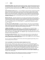
INDICATOR LIGHTS ON THE SBDS BOARD
Following is a list of the indicators (LEDs) on the SBDS board and their normal function.
LED#
1-9
10
11
12
13
14
15
16
17
18
19
20
Color
Red
Red
Yel
Yel
Yel
Yel
Grn
Yel
Yel
Yel
Yel
Red
Name
Output Fuse Open
Org+ Fuse (to reg.)
Any Lock
EE Write
Any Stop
Any Piston
5V Power
uC Scan
Set Mode
Any On
Any Off
-Piston Com
Function
When lighted the adjacent fuse is open.
When lighted the fuse is open.
Indicates a Key, Cresc or Tutti is locking out setting.
Blinks when data is actually written to memory.
Lights when one or more stops are active.
Lights when one or more pistons are active.
Indicates regulated 5V power (normally on).
Indicates the uC is running (usually on).
Indicates pistons can be set.
Blinks when there is data to turn on coils.
Blinks when there is data to turn off coils.
Indicates the negative piston common fuse is open.
(Note: + Piston Com shares Fuse F10 & LED10.)
MINI PANEL – 2 ½ digit seven segment display that is capable of showing: “+128.”.
The + sign will flash when in the Set Mode. The 128 is the maximum memory level and may be
any number 1-128. The right hand decimal point blinks when there’s a stuck piston (after 1-2
minutes).
Typical sequences of the above indicators:
System idling:
5V Power LED15 (Note: This should always be on) and uC Scan LED16 are on.
Piston press:
5V Power LED15 is on, uC Scan LED16 goes off, Any Piston LED14 comes on and the Any On
LED18 and/or Any Off LED18 blink.
Piston pressed and held:
uC Scan LED16 goes off, Any Piston LED14 comes on, the Any On LED18 and/or Any Off
LED18 blink and after a ¾ second delay the Set Mode LED17 will begin to flash repeatedly.
(Note: If two pistons are held simultaneously the Set Mode will not flash… setting prevented.)
14
Piston released after being held:
Any Piston LED14 goes off, EE Write LED12 and “+” sign blinks and uC Scan LED16 comes back on.
Set piston (only) held:
uC Scan LED16 goes off and the Set Mode LED17 will begin to flash repeatedly.
Set piston held followed by piston pressed and held:
uC Scan LED16 goes off, the Set Mode LED17 will begin to flash repeatedly, the Any Piston LED14
comes on and the EE Write LED12 and the Mini Panel + sign will blink. (Note: the flashing rate of
the Set Mode LED will slow down slightly.)
Release of piston while Set is held:
The Any Piston LED14 goes off and the flashing Set Mode LED17. (Note: the flashing rate of the Set
Mode LED will speed up again.)
Pressing GC:
uC Scan LED16 goes off, Any Piston LED14 blinks and the Any Off LED18 blinks.
Pressing Next or Previous:
Behaves the same as a piston press.
Pressing Memory Up or Memory Down:
Increments/decrements the memory level displayed on the Mini Panel. Does not affect the uC Scan
LED. (Pressing Mem Up & Mem Dn together resets to level 1.)
Stuck Piston (piston active longer than 2 minutes):
The Set Mode LED17 will stop flashing and the right decimal point on the Mini Panel will begin to
flash repeatedly.
Lock-Out active (Cresc, Tutti and/or Key):
The Any Lock LED11 lights. This will prevent the Set Mode indicator from working in any of the above
indicator sequences.
IMPORTANT PRECAUTIONS
CONTACTS for stop sensing, and piston buttons, on older organs that are being rebuilt, may be corroded
and/or pitted from prior use with unsuppressed magnets. We do our best to make our combination actions
work with poor contacts, but sometimes it becomes necessary to scrape and clean the contacts for
improved reliability.
TRANSIENT SUPPRESSION is built into our combination actions to protect the solid state components,
and to keep unsuppressed transients from other sources from interfering with its operation. We have
found, though, that on some organs without solid state switching, or where wires to other unsuppressed
magnets (such as swell Shades) are bundled in the same cables with the stop lines (going to the sense
terminals), false setting can occur. This is due to the capacitive coupling of these unsuppressed
transients in the cable. In these cases, some suppression, such as flyback diodes, may have to be added
to the interfering source. If you suspect this type of problem we will help you determine your
requirements.
Some electro-magnets (coils) manufactured by Kimber Allen use a "metal oxide varistor" ("MOV") to
suppress reverse Voltages of the coils. These devices are not sufficient to suppress the reverse
Voltage when used in connection with solid state components.
If there is any question as to whether the device is an "MOV" or a diode, remove one end from the
magnet and check the device with an Ohmmeter. Use the R X 1000 (or closest scale to it) and measure
the device with leads across the device one way, then reverse the two meter leads and measure the
other way. If it is a diode it will read low resistance one way and high resistance (or open) the other way.
If it is an "MOV" it will read the same (high) resistance both ways. If the "MOV" type device is used on
magnets wired to the "sense" inputs, diodes must be added to provide the needed protection (the MOV's
do not have to be removed). "Sense protection" boards are available from Peterson.
When CABLING, to a combination action that is remotely mounted, the output "on" and "off" coils should,
where possible, be in separate bundles from the sense and piston wires. These separate bundles can be
run next to each other as long as they are not tied tightly together. This helps prevent capacitive coupling
from the high current outputs to the low current inputs. This is especially important when using long
cables.
15
Errors in the wiring order of "on" and "off" coils and sense wires are not uncommon. It is extremely
important to match up #1 "on", #1 "off", and #1 "sense". Refer to Figures 1 and 2 in the installation
manual and to the labeling on the boards. Be absolutely sure of the wiring order before proceeding.
TESTING OF WIRING with a "buzzer" should not be done unless all connectors are unplugged and
not connected to solid state components. "Buzzers" can have reverse Voltages (flyback Voltages) of
100V or more, just like other magnets, but in a "Buzzer", these Voltage transients occur at the "Buzz" rate
(frequency). This can destroy solid state parts instantly. A safer method is to use a low Voltage continuity
(lamp) tester or Ohm meter.
THE CONDUCTOR SIZES of the wires used for connecting the organ positive to the SBDS and the organ
negative to the stop action magnets are important. Bear in mind that the positive ( + ), to the SBDS board
has to be sufficient size to carry the feed current to all the stop action magnets simultaneously. Likewise,
the negative (-) to the "on" and "off" coil returns must be of sufficient size to carry return current from all
stop magnets simultaneously.
A full SBDS board (64 stops) operating on a 15V power supply assuming 30 Ohm coils will draw 28
AMPS and would require a #8 wire, for both the positive feed to the SBDS board and negative return from
the stop magnets. (Short runs within a console may use #10-#12.) The negative to the SBDS board will
not draw more than 2 AMPS and a #18 wire is adequate. Individual coil wires will draw approximately 1/2
AMP, and #28 wire is all that is required for these. These wire sizes apply to the short runs within the
console only. Note that 20 feet of #8 wire with 28 AMPS flowing through it will drop about .36 Volt. Wire
size should be increased for longer runs. Bear in mind that an increase of 3 wire sizes (for example 12 to
9) will reduce the resistance (and Voltage drop) by half.
ALUMINUM WIRE and aluminum lugs are NOT recommended for use in feed and/or return conductors.
This applies to any brand or type of combination action or relay. Aluminum wire or lugs that are bolted or
screwed to a buss or junction will flow over a period of time, and become loose. When aluminum must be
used, be sure to use terminating lugs designed for aluminum wire, that when properly installed, minimize
the flow problem.
SOLDERING of wires to connector pins is important. Wire wrapping alone is not recommended. Under
no conditions should acid flux be used. We recommend using 60/40 rosin core solder. (Rosin flux may
be brushed on if care is taken to avoid getting flux into the connector where contact is made. If magnet
wire (or other coated wire) is used be sure enough heat is used to break down the insulation and that the
solder is not just covering the wire, but bonding it to the pin. So called "No-Korrode" solder paste is in fact
extremely corrosive, and should never be used anywhere around the electrical parts of an organ.
ORGAN POWER SUPPLIES (rectifiers) have an important part to play in how well the completed
installation will operate. In general the organ supply should be capable of supplying enough current to
operate all the stop action magnets and the chest magnets, etc. The nominal Voltage should be 10.5
VDC to 18 VDC. At no time should the output Voltage drop below 8.5 VDC or exceed 25 VDC during
surges caused by peak demands. Other transients greater than 50 VDC should not exceed 1 millisecond
in length. These surges and transients usually cannot be measured with a Voltmeter. A "Power Supply
Fault Detector", available from Peterson, detects Voltage outside the normal, safe operating range of
Peterson and most other brands of solid state equipment for pipe organs. Even extremely short transients
will cause a high level or low level indicator LED to latch on. We recommend checking any old or
questionable rectifier with our Fault Detector, especially if any problems are encountered when using
solid state equipment. A Teset & Power Junction with “Fault Detector” is provided with each mounted and
wired system. The minimum Voltage under full load can also be measured with a Voltmeter while
reiterating the general cancel button.
RECTIFIERS OF INADEQUATE SIZE will cause the stop actions to appear sluggish or slow or “forgetful”
or dead. This is most apparent on general pistons or cancel. To approximate the capacity of the rectifier
required, divide the total number of stops by two, then add 10% of that number to it. Example: 50 stops
divided by 2 = 25 + 2.5 = 27.5 AMPS. This is the current required for the combination action only. If the
organ has all electric chest actions, considerably more current may be required. (See worksheet page
15).
SOME RECTIFIER DESIGNS are not as good as others, and may not be suitable for use with the
combination action. This is due to the brief high peak currents that are required to work all the stop action
16
magnets (coils). Older rectifiers that use SELENIUM RECTIFIERS have a higher resistance, which can
cause severe Voltage drops. These rectifiers (diodes) can be identified by their appearance. Selenium
rectifiers are made with many plates stacked and bolted together with one large bolt (some times referred
to as bread slicers). Also, RECTIFIERS THAT USE A "CHOKE" filter in their output are less desirable.
The "choke" resists the flow of current at the peak demand, causing a momentary Voltage drop. Also,
when the load is removed, the "choke's" magnetic field collapses and induces a Voltage greater than the
normal output. This can be observed by watching the brilliance of any incandescent pilot lamp. The lamp
will dim at the moment of demand, and flash brighter when the load is removed.
GENERATORS OR MOTOR-GENERATOR SETS seem to work fairly well. However, a large value
capacitor may have to be added to eliminate "hash" and other transients. (See "additional capacitors")
A MORE SUITABLE RECTIFIER design is the type that uses a constant Voltage transformer and
capacitor filters. The peak demand current is supplied by the energy stored in the capacitors, while the
transformer automatically adjusts itself to maintain a steady Voltage. Transients generated elsewhere in
the organ are also filtered by the output capacitors. This type of design can be severely overloaded (even
short circuited) without damaging the unit. Also, greater peak demands can be supplied with the use of
ADDITIONAL CAPACITORS. (A good rule of thumb is 1000 MFD. per stop). The use of additional
capacitors with other rectifier designs may work; however, interaction between the "choke" (inductor) and
the capacitor(s) can cause "ringing" in the output Voltage (pilot lamps would flutter). This kind of situation
can cause malfunctions in the combination action.
THE MOST SUITABLE RECTIFIER is a modern “switching” or “switch mode” type power supply. This
type of rectifier is very compact in size for the amount of current they supply. The regulation is excellent
and these supplies are well protected for over-load and short circuits. Peterson supplies these under the
name “Inteli Power®” in 40 Amp, 60 Amp and 80 Amp sizes. Feel free to contact us at 800-341-3311 or
review the Peterson catalog for further information.
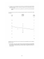
LOCATION OF THE RECTIFIER and the size of the conductors from it to the combination action are also
important. Too small a conductor for too long a run can cause Voltage drops that will adversely affect
performance. The following chart shows Voltage drops per 100 feet with various size conductors. The
actual drop would be doubled considering both feed and return lines. (See the chart on page 20 for
selecting conductor sizes).
STOP ACTION MAGNETS manufactured by Syndyne Corp. have been known to cause erratic operation
if the polarity of the stop action magnet does not match the polarity required by the combination action.
The "SAM" polarity is determined by the termination of the coil wires and the direction of the magnetic
poles of the permanent magnets. When the wrong polarity is used residual magnetism on the pole
magnet may pull in the reed switch when the stop is turned off. Magnetic fields of adjacent "SAMs" may
also affect the reed switch and cause erratic operation. Therefore, it is important to specify the proper
polarity when ordering stop action magnets. Do not reverse the polarity of the coil common unless you
reverse the coil wires, or another alternative would be to use inverters. Stop actions by Harris or some
others will not work with reversed polarity.
If you have any unanswered questions regarding the installation, testing, or operation of any of our
products, give us a call at (800) 341-3311 or (708) 388-3311.
We would appreciate any comments to help us improve our installation and instruction manual, drawings,
or labeling. If anything is incomplete, unclear or inaccurate, let us know.
THANK YOU,
PETERSON ELECTRO-MUSICAL PRODUCTS, INC.
11601 South Mayfield Avenue
Alsip, Illinois 60803
17
18
19
20
SBDS SPECIFICATION
March, 2009
MEMORY
EEPROM (U10) for non-volatile storage (no batteries)
128 levels
Memory Select via:
Mini Panel with 2 ½ digit 7 segment Read Out and Rotary Knob
Knob press resets to level 1 (one)
Standard Mini Panel cable is 10’ dual 14 pin ribbon cables (CN1 & CN2).
Memory Up/Down Buttons/Pistons (on JM1)
Pressing Up and Down together resets to level 1 (one).
Can be operated as a single level combination action without the Mini Panel.
STOPS
64 stops maximum.
Stop divisions are selectable as:
3 manual: 16 Sw, 16 Gt, 12 Ch, 12 Pd, 8 Coupler (Gen Only)
2 manual: 20 Sw, 20 Gt, 16 Pd, 8 Coupler (Gen Only)
Sense inputs: Positive or Negative sense - field selectable (using jumper JS9)
PISTONS
64 settable piston inputs
Piston inputs are selectable as:
3 man: 32 Gen, 8 Sw, 8 Gt, 8 Ch, 8 Ped
2 man: 24 Gen, 16 Sw, 16 Gt, 8 Ped
Duo-Set (Tripper and Capture)
Piston inputs: Positive or Negative - field selectable (JP9)
Pedal Piston Couplers activated via DIP switch (S1) or external sense inputs (on JR1)
Polarity follows other sense input polarities
“European” Piston Sequencer via Next/Previous buttons (on JM1)
Wraps levels at transition between General 1 and the highest-numbered General
Also wraps level between 128 and 1.
A DIP switch (S1) must be set to the actual number of Generals used minus 1
Pressing Next & Previous together resets the sequence to General 1 on Level 1
OTHER INPUTS
Set, GC, Cresc Lock-Out, Tutti Lock-Out, Pedal Piston Couplers (3), Piston Sequencer Next/Previous, 4
Lock-Outs for 4 Groups of 32. (1-32, 33-64, 65-96, 97-128). Positive input only. (Lock-out inputs can be
tied together to create other group sizes or lock everything)
Reversibles
4 regular reversibles that can be wired in parallel with any of the 64 stops
Or wired to their own stops
One ON coil output and three OFF coil outputs (JR2 & JR3).
Sense polarity follows stops sense polarity.
OUTPUTS
IC (socketed) coil drivers, positive out (neg coil com), 800 mA max. load
15 Ohms @ 13.6V or 20 Ohms @ 18V maximum coil loads
Negative out (pos coil com) available with alternate assembly (different ICs - not field selectable)
Coil On Time (DIP switch) selectable (S2) for 100 mS - 450 mS in 8 selectable 50 mS increments
Built-in fuse protection using 6A PTC resettable fuses
Operating Voltage range: 10.5 – 18.0V DC (13.6V nominal)
FIELD SELECTABLE OPTIONS
Primary/Secondary (formerly Master/Slave) program jumper (JP19) and 14 pin ribbon cable (CN6)
With Primary selected the ribbon cable connector outputs memory level and piston address data
With Secondary selected the memory level and PSQ piston address track the Primary.
2-3 Manual program jumper (JM3)
21
Selects 2 or 3 manual piston/stop divisions accordingly
Piston Polarity program jumper (JP9)
Selects positive or negative inputs.
Sense Polarity program jumper (JS9)
Selects positive or negative inputs
Pneumatic Mode (DIP switch S2)
Coil On Time (3 DIP switches S2)
100 mS - 450 mS in 8 selectable 50 mS increments
Static Pedal Piston Coupler (3 DIP switches S1)
One each for Swell, Great and Choir (over-rides PPC stop input)
Maximum Generals (5 DIP switches S1)
Selects binary number for the actual number of general pistons
Labeled 1, 2, 4, 8 & 16. The max. # of generals equals the sum of switches that on -1
Example: For 10 generals, subtract 1 = 9. Set the DIP switches to = 9. Turn on #1 & #8
INDICATORS
Mini Panel:
2 ½ digit 7 segment read out for levels 1-128
Flashing “+” sign indicates Set Mode when memory can be written
Flashing decimal point indicate a stuck piston (after 2 minutes)
Discrete:
UC Scan (yel), Set Mode (yel), EE Write (yel), Any Piston (yel), Any Stop (yel), Any Lock (yel),
Any On Coil (yel), Any Off Coil (yel), 5v Power (green), Ten (10) Fuse open indicators (red)
PHYSICAL
Connectors: Pistons, On, Off and Sense use 0.156 inch Peterson “EZ Wire”, “Output Connector”, or
“Quick Punch” IDC punch down connector systems
Single PCB. 4 layer, SMT
Size: 17.375" x 7.35"
Recommended Operating Temperature Range 50F-125F (100F max with 18V organ supply)
Scanning (refresh) rate ~1 mS
JTAG and BDM connectors for factory programming
EXTERNAL OPTIONS
Sforzando/Tutti: Uses Peterson Sforz Reversible (400365) and Stops Junction method
“Jumper Wire” crescendo uses Peterson Stops Junction method
“Last General Pressed” Read Out Option (CN8) for displaying the piston number in a two digit seven
segment display or to operate lighted pistons
OTHER
Two SBDS boards can be wired in parallel to expand stops or pistons depending on the wiring
When used to expand the number of stops, the Primary/Secondary (formerly Master/Slave)
option provides the memory level address from the Primary’s Mini Panel to the Secondary unit
PETERSON ELECTRO-MUSICAL PRODUCTS, INC.
11601 South Mayfield Ave., Alsip, IL 60803-2476
Phone: 1(708)388-3311 Toll-Free: 1(800)341-3311
email: [email protected] FAX: 1-708-388-3367
22