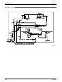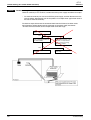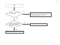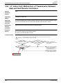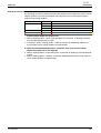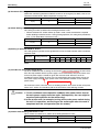
1
1/ 18 December 4, 2009 ★Reliable technology ensures maximum customer satisfaction.★ Case Correction in Service manual SiIN34-817 VRV3 Model RXYQ5-54PAY6 M-09011 ■Notice There are some corrections in the service manual of SiIN34-817. The corrections will be revised in the next issue. ■ Applicable Book and Page SiIN34-817 P340,67,336,308,127,90,63,61,63,65,70,71,174,203 P184,267 ■ Detail For correct information, refer to the following pages. 2/18 Piping Diagrams SiIN34-817 RXYQ10PA / 12PAY6 STD1 3D061122A 340 Appendix 3/18 SiIN34-817 Functional Parts Layout 2. Functional Parts Layout 2.1 RXYQ5PA Plan Accumulator ass'y Heat exchanger ACCUMULATOR THERMISTOR Front View THERMISTOR R7T 4 way valve (Y3S) Solenoid valve (Hot gas bypass) (Y1S) Pressure switch (High pressure protection) (S1PH) THERMISTOR THERMISTOR ELECTRONIC EXPANSION VALVE THERMISTOR Solenoid valve (Accumulator oil return) (Y2S) THERMISTOR (R6T) Liquid pipe Refirgerant Circuit 67 4/18 Troubleshooting (OP: Unified ON/OFF Controller) SiIN34-817 CHECK 5 Troubleshooting for Power Supply Transformer Check for continuity in F1U and F2U, and then check the power supply transformer for output. * To check for continuity, be sure to turn OFF the power supply, and then dismount the fuse from the holder. Subsequently, put the test probes of a multiple meter against both ends of the fuse to check for continuity. To check for output, disconnect the connector X23A from the PC board, and then make measurement of output voltage from the connector on the power supply transformer. *To make this measurement, set the multiple meter to the AC range. Is there continuity in F1U and F2U? NG YES Is output voltage from the power supply transformer not less than 19VAC? Since a layer short circuit is established in any part on the PC board or in any actuator, check for it. After checking, replace F1U and F2. NG YES The power supply transformer is normal. 336 Replace the power supply transformer. Troubleshooting 5/18 Start NO Is there continuity in F1U and F2U? Since a layer short circuit is established in any part on the PC board or in any actuator, check for it. After checking, replace F1U and F2U. YES Is output voltage from the power supply transformer not less than 19VAC? YES The power supply transformer is normal. NO Replace the power supply transformer. 6/18 Troubleshooting by Indication on the Remote Controller SiIN34-817 3.52 “U8” Indoor Unit: Malfunction of Transmission Between Main and Sub Remote Controllers U8 Remote Controller Display Applicable Models All models of indoor units Method of Malfunction Detection In case of controlling with 2-remote controller, check the system using microcomputer if signal transmission between indoor unit and remote controller (main and sub) is normal. Malfunction Decision Conditions Normal transmission does not continue for specified period. Supposed Causes Malfunction of transmission between main and sub remote controller Connection between sub remote controllers Defect of remote controller PC board Troubleshooting Caution Be sure to turn off power switch before connect or disconnect connector, or parts damage may be occurred. Using 2-remote controllers control. NO YES SS1 of both remote controllers is setto "SUB." YES SS1 of remote controller PC boards is set to "MAIN." NO Set SS1 to "MAIN"; the power supply off once and then back on. YES NO Turn the power off and then back on. If a malfunction occurs, replace the remote controller PC board. Set one remote controller to "MAIN"; the power supply off once and then back on. set to "SUB" 308 Troubleshooting 7/18 SiIN34-817 4.5 Protection Control STD Compressor Overload Protection This control is used to prevent abnormal heating due to overcurrent to the compressor resulting from failures of STD compressor such as locking. STD compressor ON Demand to operate. *If the power supply is reset while in operation prohibition mode, the prohibition timer will continue counting when the power supply is turned ON. CT detection current value>15.0A(Y6) STD compressor OFF for 30 min.* When occurring 3 times within 90 minutes, the malfunction code “ E6 ”is output. 4.6 Injection Control (only for RXYQ5PA) For transitional rise in discharge pipe temperature, have the liquid refrigerant flow into the suction side to reduce the discharge pipe temperature for the compressor protection. SVT = OFF HTdi: Correction value of the discharge pipe HTdi>112˚C HTdi<107˚C SVT = ON Function temperature on the INV compressor. HTdi: Value of INV compressor discharge pipe temperature (Tdi) compensated with outdoor air temperature 127 8/18 Function General SiIN34-817 1. Function General 1.1 Symbol Symbol Electric symbol Description or function 20S1 Y3S Four way valve (Energize during heating) DSH – Discharge pipe superheated degree DSHi – Discharge pipe superheat of inverter compressor DSHs – Discharge pipe superheat of standard compressor EV – Opening of electronic expansion valve EV1 Y1E Electronic expansion valve for main heat exchanger EV2 Y2E Electronic expansion valve for sub-coolig heat exchanger HTDi – Value of INV compressor discharge pipe temperature (R31T) compensated with outdoor air temperature HTDs – Pc S1NPH Pe S1NPL Value detected by low pressure sensor SH – Evaporator outlet superheat SHS – Target evaporator outlet superheat SVO Y2S Solenoid valve for oil return SVP Y1S Solenoid valve for hot gas bypass HTdi Value of STD compressor discharge pipe temperature (R32T, R33T) compensated with outdoor air temperature HTds Value detected by high pressure sensor SVT Y4S Solenoid valve for injection Ta R1T (A1P) Outdoor air temperature Tb R4T Heat exchanger outlet temperature at cooling Ts2 R2T Suction pipe temperature detected with the suction pipe thermistor (R2T) Tsh R5T (–) Temperature detected with the subcooling heat exchanger outlet thermistor (R5T) Tc – High pressure equivalent saturation temperature TcS – Target temperature of Tc Te – Low pressure equivalent saturation temperature TeS – Target temperature of Te Tfin R1T Inverter fin temperature Tl R6T Liquid pipe temperature detected with the liquid pipe thermistor (R6T) Tp – Calculated value of compressor port temperature Ts1 R7T Suction pipe temperature detected with the accumulator inlet thermistor 90 Function 9/18 SiIN34-817 Refrigerant Circuit RXYQ10PA, 12PA E S1PH V F U 5 6 8 D M 7 N 1 G Q P 3 4 A X B W J O 2 3D061122A High Pressure Switch S1NPH S1NPL Refirgerant Circuit High Pressure Switch S2PH 63 10/18 SiIN34-817 Refrigerant Circuit RXYQ8PA E V F 5 T 4 7 D M 6 N S1PH 1 G S1NPH P 3 W A O J 2 S1NPL Refirgerant Circuit 3D061121A 61 11/18 SiIN34-817 Refrigerant Circuit RXYQ10PA, 12PA E V F U 5 6 S1NPH 8 D M 7 S2PH N 1 G Q P 3 4 A X B W J O 2 3D061122A S1PH High Pressure Switch S1NPL Refirgerant Circuit 63 12/18 SiIN34-817 Refrigerant Circuit RXYQ14PA, 16PA, 18PA S1NPH 7 E V F 6 9 U D M N 8 G 1 P R Q 3 A 4 X W 5 B Y C J O 2 S2PH S1PH Refirgerant Circuit S1NPL S3PH 3D061123A 65 13/18 Functional Parts Layout 2.4 SiIN34-817 RXYQ12PA Plan Heat exchanger PRESSURE SWITCH (HIGH PRESSURE PROTECTION) (S2PH) Accumulator PRESSURE SWITCH (HIGH PRESSURE PROTECTION) (S1PH) THERMISTOR (MIC, DISCHARGE PIPE) (R31T) THERMISTOR (M2C, DISCHARGE PIPE) (R32T) Front View FAN MOTOR (M2F) FAN MOTOR (M1F) THERMISTOR (R5T) THERMISTOR (R7T) (S1NPH) ELECTRONIC (Y2E) ELECTRONIC (Y1E) THERMISTOR (Y3S) (R1T) (Y1S) THERMISTOR (R4T) THERMISTOR (R6T) (M1C) (S1NPL) (Y2S) (E2HC) (E1HC) (M2C) THERMISTOR (R2T) COMP.LEAD WIRE(INVERTER) 70 (M1C) CRANK CASE HEATER WIRE (M2C) COMP.LEAD WIRE(STD1) Refirgerant Circuit 14/18 SiIN34-817 2.5 Functional Parts Layout RXYQ14PA, 16PA, 18PA Plan Heat exchanger Accumulator THERMISTOR THERMISTOR THERMISTOR Front View THERMISTOR THERMISTOR ELECTRONIC ELECTRONIC THERMISTOR THERMISTOR COMP.LEAD WIRE(STD2) THERMISTOR THERMISTOR COMP.LEAD WIRE(INVERTER) Refirgerant Circuit COMP.LEAD WIRE(STD1) 71 15/18 SiIN34-817 Field Setting Setting of Demand Operation By connecting the external contact input to the demand input of the outdoor unit external control adaptor (optional), the power consumption of unit operation can be saved suppressing the compressor operating condition. Set item Demand 1 Condition Content Mode 1 Mode 2 The compressor operates at approx. 60% or less of rating. The compressor operates at approx. 70% or less of rating. Demand 2 Mode 3 The compressor operates at approx. 80% or less of rating. The compressor operates at approx. 40% or less of rating. Demand3 --------- Forced thermo OFF A. When the demand operation is carried out by external instructions (with the use of the external control adaptor for outdoor unit). 1. While in "Setting mode 2", set the setting condition for set item No. 12 (Setting of external low noise/demand operation) to "YES". 2. If necessary, while in "Setting mode 2", select the set item No. 30 (Setting of Demand 1 level) and then set the setting condition to targeted mode. B. When the normal demand operation is carried out. (Use of the external control adaptor for outdoor unit is not required.) 1. While in "Setting mode 2", make setting of the set item No. 32 (Setting of constant demand) to "ON". 2. While in "Setting mode 2", select the set item No. 30 (Setting of Demand 1 level) and then set the setting condition to targeted mode. Test Operation 203 16/18 Field Setting SiIN34-817 (8) Thermostat Switching Differential value during thermostat ON/OFF control can be changed. (For details, refer to "6.4 Thermostat Control while in Normal Operation" on page 141.) Mode No. First Code No. 12(22) 2 Second Code No. 01 Differential value 1ºC 02 0.5ºC (9) Airflow Setting when Heating Thermostat is OFF This setting is used to set airflow when heating thermostat is OFF. ∗ When thermostat OFF airflow volume up mode is used, careful consideration is required before deciding installation location. During heating operation, this setting takes precedence over "(7) Fan Stop When Thermostat is OFF." Mode No. First Code No. 12 (22) 3 Second Code No. 01 Contents LL airflow 02 Preset airflow (10) Setting of Operation Mode to "AUTO" This setting makes it possible to change differential values for mode selection while in automatic operation mode. Mode No. Setting switch No. 12 (22) 4 01 02 Setting position No. 03 04 05 06 0°C 1°C 2°C 3°C 4°C 5°C 07 08 6°C 7°C The automatic operation mode setting is made by the use of the "Operation Mode Selector" button. (11) Auto Restart after Power Failure Reset For the air conditioners with no setting for the function (same as factory setting), the units will be left in the stop condition when the power supply is reset automatically after power failure reset or the main power supply is turned on again after once turned off. However, for the air conditioners with the setting, the units may start automatically after power failure reset or the main power supply turned on again (return to the same operation condition as that of before power failure). (same as factory setting) For the above reasons, when the unit is set enabling to utilize “Auto restart function after power failure reset”, utmost care should be paid for the occurrence of the following situation. Caution 1. The air conditioner starts operation suddenly after power failure reset or the main power supply turned on again. Consequently, the user might be surprised (with question for the reason why). 2. In the service work, for example, turning off the main power switch during the unit is in operation, and turning on the switch again after the work is completed start the unit operation (the fan rotates). (12) Airflow when Cooling Thermostat is OFF This is used to set airflow to "LL airflow" when cooling thermostat is OFF. 174 Mode No. First Code No. 12 (22) 6 Second Code No. 01 Contents LL airflow 02 Preset airflow Test Operation 17/18 Field Setting 3.2 SiIN34-817 Field Setting from Outdoor Unit 3.2.1 Field Setting from Outdoor Unit List of Field Setting Items This following section indicates the list of field setting items. For the lists of dip switch contents, Setting mode 1, and Setting mode 2, refer to information in tables shown on the following page onward. Setting item Content and objective of setting Overview of setting procedure COOL/HEAT selection methods are possible to select from the following (1) Control by each outdoor unit using the In order to use the COOL/HEAT selection indoor unit remote controller remote controller, set the DS1-1 on the (2) Control by each outdoor unit using the outdoor unit PC board to OUT. COOL/HEAT selection remote For outdoor unit group control, set the controller system to "BATCH MASTER" or "SLAVE" (3) Batch control by outdoor unit group while in "Setting mode 1". Then, make using the indoor unit remote controller setting of COOL/HEAT batch address. (4) Batch control by outdoor unit group using the COOL/HEAT selection remote controller Setting of COOL/ HEAT selection (*1) 2 A. Use external input to step down the upper Use the "External control adaptor for limit of the fan (factory set to Step 8), outdoor unit". providing low noise level. Set to "External control adaptor for outdoor (1) Mode 1: Step 6 or lower unit" with No. 12 of "Setting mode 2" and (2) Mode 2: Step 5 or lower select the mode with No. 25. (3) Mode 3: Step 4 or lower If necessary, set the "Capacity priority setting" to ON with No. 29. B. The low noise operation aforementioned is Setting of low noise enabled in nighttime automatic low noise operation (*1) Make this setting while in "Setting mode 2". operation mode. Select a mode with No. 22 of "Setting mode Start time: Possible to select in the range of 2". 20:00 to 24:00 hours. Select the start time with No. 26 and the End time: Possible to select in the range of end time with No. 27. 06:00 to 08:00 hours. If necessary, set the "Capacity priority (Use the said time as a guide since the setting" to ON with No. 29. start time and the end time are estimated according to outdoor temperatures.) Function setting 1 3 4 5 6 Used to place limits on the compressor For setting with the use of "external control operating frequency to control the upper adaptor": limit of power consumption. Set the system to "External control adaptor (1) Mode 1 of Demand 1: 60% or less of for outdoor unit" with No. 12 of Setting mode 2" and select the mode with No. 30. Setting of demand rating operation (*1) (2) Mode 2 of Demand 1: 70% or less of For setting only in "Setting mode 2": rating Set the system to Normal demand mode (3) Mode 3 of Demand 1: 80% or less of with No. 32 of "Setting mode 2" and select rating the mode with No. 30. (4) Demand 2: 40% or less of rating Used to make address setting with AirNet Set the AirNet to an intended address Setting of AirNet connected. using binary numbers with No. 13 of address "Setting mode 2". Setting of hot water Make this setting to conduct heating Set No. 16 of "Setting mode 2" to ON. heater operation using the hot water heater. Make this setting to operate a system with diffuser duct while in high static pressure Setting of high mode. (Use this setting mode when shields static pressure are installed on upper floors or balconies.) Set No. 18 of "Setting mode 2" to ON. * In order to mount the diffuser duct, remove the cover from the outdoor unit fan. • For setting items of (*1), refer to detailed information provided on page 196 onward. (5) Demand3: Forced thermo OFF 184 Test Operation 18/18 SiIN34-817 Troubleshooting by Indication on the Remote Controller Troubleshooting Caution Be sure to turn off power switch before connect or disconnect connector, or parts damage may be occurred. Turn power supply off, and turn power supply on again. Return to normal? YES NO Electronic expansion valve is connected to X21A and X23A of outdoor unit PC board (A1P). NO * X26A only for RXYQ5PA External factor other than malfunction (for example, noise etc.). After connecting, turn the power off and then back on again. YES Normal when coil check (∗1) of the moving part of the electronic expansion valve is checked. NO Replace the moving part of the electronic expansion valve. YES The connecting cable is short-circuited or disconnected. YES NO Replace the connecting cable. Replace outdoor unit PC board (A1P). ∗Make measurement of resistance between the connector pins, and then make sure the resistance falls in the range of 40 to 50Ω. (Orange) 1 (Red) 2 (Yellow) 3 (Black) 4 5 Measuring points 1-6 2-6 3-6 4-6 (Gray) 6 Troubleshooting 267