1
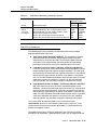
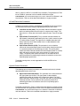
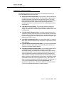
WaveStar™ OLS 40G
Release 3.4
User/Service Manual
365-575-536 ADD
Issue 4
November 2003
Copyright © 2003 Lucent Technologies. All Rights Reserved.
This material is protected by the copyright laws of the United States and other countries. It may not be
reproduced, distributed, altered in any fashion by any entity (either internal or external to Lucent
Technologies), except in accordance with applicable agreements, contracts or licensing, without the express
written consent of the Customer Training and Information Products organization and the business
management owner of the material.
For permission to reproduce or distribute this document please contact your Account Executive.
Notice
Every effort was made to ensure that the information in this document was complete and accurate at the time
of printing. However, information is subject to change.
Federal Communications Commission (FCC) Statement
This equipment has been tested and found to comply with the limits for a Class A digital device, pursuant to
Part 15 of FCC Rules. These limits are designed to provide reasonable protection against harmful
interference when the equipment is operated in a commercial environment. This equipment generates, uses,
and can radiate radio frequency energy, and, if not installed and used in accordance with the instruction
manual, may cause harmful interference to radio communications. Operation of this equipment in a residence
is likely to cause harmful interference in which case the user will be required to correct the interference at his
own expense.
Security
In rare instances, unauthorized individuals make connections to the telecommunications network through the
use of remote access features. In such event, applicable tariffs require that the customer pay all network
charges for traffic. Lucent Technologies cannot be responsible for such charges and will not make any
allowance or give any credit for charges that result from unauthorized access.
Trademarks
5ESS, DACScan, LGX, ST, and TrueWave are registered trademarks of Lucent Technologies
WaveStar is a trademark of Lucent Technologies
ANSI is a registered trademark of American National Standards Institute, Inc.
Common Language is a registered trademark and CLEI, CLLI, CLCI, and CLFI are trademarks of Telcordia
CSA is a registered trademark of the Canadian Standards Association
DANTEL is a registered trademark of DANTEL Inc.
Harris is a registered trademark of Harris Corporation
IBM is a registered trademark of International Business Machines Corporation
Microsoft, MS-DOS, and Windows 95, Windows 98, Windows NT, and Windows 2000 are registered
trademarks of Microsoft Corporation
Pentium is a registered trademark of Intel Corporation
Styrofoam is a registered trademark of the Dow Chemical Company
UL is a registered trademark of Underwriters Laboratories, Inc.
Warranty
The terms and conditions of sale will include a one-year warranty on hardware and applicable software.
Customer Assistance and Technical Support
The Lucent Technologies North American Regional Technical Assistance Center (NARTAC) provides a
technical assistance telephone number that is monitored 24 hours a day. For technical assistance, call
1-800-225-RTAC (1-800-225-7822). You can also call this telephone number to provide comments on
the product or to suggest enhancements.
International customers, please either call +1-630-224-4672: Prompt 2 or contact your Account Executive for
your local technical support number.
This document was developed by the Lucent Technologies Optical Networking Group, Lucent Learning
Organization.
1
Addendum
Overview
.............................................................................................................................................................................................................................................................
Purpose
Instructions
This addendum provides the following:
•
Information about the LEA107B circuit pack, which is compatible
with Release 3.4.2.
•
A new "Appendix D: Power Down/Power Up an Optical Network
Element (NE)."
•
An updated TAP-153, "Clear Combination ‘TLM Failure’ and
‘OA Failure."
•
Updated "Optical Line Parameter" information in the
"Performance Monitoring" section of Chapter 9.
•
Updated Detailed Level Procedure 514 (DLP-514).
Please insert the parts of this addendum into the WaveStar™ OLS 40G
Release 3.4 User/Service Manual according to the following table.
Addendum Section
Location in the User Service Manual
Addendum Overview (this page)
Front (just after title page)
Appendix D: Power Down/Power Up an
Optical Network Element (NE)
Just before Glossary
TAP-153: Clear Combination ‘TLM
Failure’ and ‘OA Failure’
In place of existing TAP-153
............................................................................................................................................................................................................................................................
365-575-536 ADD
Issue 4 November 2003
Lucent Technologies - Proprietary (Restricted)
Solely for authorized persons having a need to know
pursuant to Company instructions
1 - 1
Overview
Addendum
Addendum Section
Location in the User Service Manual
Performance Monitoring (Pages 9-27
through 9-36)
In place of existing Pages 9-27 through 9-36
DLP-514: Install/Remove Circuit Pack
In place of existing DLP-514
...........................................................................................................................................................................................................................................................
1 - 2
Lucent Technologies - Proprietary (Restricted)
Solely for authorized persons having a need to know
pursuant to Company instructions
365-575-536 ADD
Issue 4 November 2003
Addendum
.............................................................................................................................................................................................................................................................
LEA107B
OMON Port
Supervisory Channel
The LEA107B can be used in place of the LEA104. The engineering
rues and output specifications are the same. The difference between the
LEA107B and the LEA104 are described in the following sections.
The LEA107B includes an optical monitoring test port at the optical
amplifier output. The port enables the customer to monitor data
channels using an optical spectrum analysis instrument.
The LEA107B uses a dual filter to support either a 1510nm or 1532nm
optical supervisory channel (OSC).
............................................................................................................................................................................................................................................................
365-575-536 ADD
Issue 4 November 2003
Lucent Technologies - Proprietary (Restricted)
Solely for authorized persons having a need to know
pursuant to Company instructions
1 - 3
Appendix D: Power Down/Power Up
an Optical Network Element (NE)
Overview
.............................................................................................................................................................................................................................................................
Purpose
This procedure is designed to help Lucent customers prepare for a
planned loss of power to all or part of a central office. The loss of
power to any NE will cause a loss of traffic on that NE, so traffic must
be rerouted around the NE. Because there are so many variations from
product to product, this procedure is written at a high level. See the
specific product documentation if you need more details for any step.
Personnel
The personnel performing this procedure should have knowledge of the
specific product being powered down and/or powered up and should
have access to specific product documentation so that they can
determine whether the NE is functioning properly and address any
problems that may occur.
Shelf power
Any shelf that receives electrical power has either two (A and B) circuit
breakers or two (A and B) fuses. Most NE shelves do receive electrical
power. The circuit breakers or fuses may be located on the shelf itself
or at the top of the bay frame.
............................................................................................................................................................................................................................................................
365-575-536 ADD
Issue 4, November 2003
Lucent Technologies
D - 1
Power Down/Power Up an Optical Network Element (NE)
Power Down an Optical Network Element (NE)
.............................................................................................................................................................................................................................................................
CAUTION
Electrostatic Discharge
Use a static ground wrist strap whenever handling circuit
packs or working on a network element to prevent
electrostatic discharge (ESD) damage to sensitive
components.
...........................................................................................................................................................................
1
Reroute traffic around the NE.
............................................................................................................................................................................
2
Power down each shelf in one of the following ways:
•
Shut off both A and B circuit breakers by inserting an object such
as a thin flathead screwdriver into the slot on the "off" side of each
circuit breaker.
•
Remove both A and B fuses by lifting the cover, then pressing in
and down, then releasing to allow the fuse to spring outward.
............................................................................................................................................................................
3
Shut off power at the Battery Distribution Feeder Bay (BDFB)
END OF STEPS
...........................................................................................................................................................................
...........................................................................................................................................................................................................................................................
D - 2
Lucent Technologies
365-575-536 ADD
Issue 4, November 2003
Power Down/Power Up an Optical Network Element (NE)
Power Up an Optical Network Element (NE)
.............................................................................................................................................................................................................................................................
CAUTION
Electrostatic Discharge
Use a static ground wrist strap whenever handling circuit
packs or working on a network element to prevent
electrostatic discharge (ESD) damage to sensitive
components.
...........................................................................................................................................................................
1
Make sure that the circuit breakers are off or the fuses are removed from
the network element.
Result: This eliminates any chance of one person powering up at
the Battery Distribution Feeder Bay (BDFB) while someone else
could be exposed to electrical power at the network element.
............................................................................................................................................................................
2
Turn on the power supply to this network element at the BDFB.
............................................................................................................................................................................
3
Continue with the next step for the shelf containing the system controller
circuit pack.
............................................................................................................................................................................
4
Power up the shelf and verify that both A and B power supplies are good
as follows:
1.
Turn on circuit breaker A or insert fuse A and press inward and
upward.
If the green power on LED is not lit, check for a reversal on the
power feeder and verify there is voltage at the connector.
2.
Turn off circuit breaker A or remove fuse A.
3.
Turn on circuit breaker B or insert fuse B and press inward and
upward.
If the green power on LED is not lit, check for a reversal on the
power feeder and verify there is voltage at the connector.
............................................................................................................................................................................................................................................................
365-575-536 ADD
Issue 4, November 2003
Lucent Technologies
D - 3
Power Down/Power Up an Optical Network Element (NE)
4.
Turn on circuit breaker A or insert fuse A and press inward and
upward.
Result: You have verified that both A and B power supplies are
good and are now turned on.
............................................................................................................................................................................
5
Wait for all of the circuit packs on this shelf to finish booting, indicated
by the following:
•
all red LEDs are off
•
for packs with green LEDs, they are on steadily.
............................................................................................................................................................................
6
Repeat Step 4 and Step 5 for all other shelves that contain controller
circuit packs.
............................................................................................................................................................................
7
Repeat Step 4 and Step 5 for all shelves that do not contain any
controller circuit packs.
............................................................................................................................................................................
8
Log into the network element with a craft interface terminal and check
alarms.
............................................................................................................................................................................
9
If any alarms appear, use the product documentation to clear them. For
most products, the appropriate document will be an Alarm Message and
Trouble Clearing Guide or a User/Service Manual.
............................................................................................................................................................................
10
If this NE allows cross-connection, verify that the cross-connections are
correct. Refer to the appropriate product documentation, usually a User
Operations Guide or a User/Service Manual.
............................................................................................................................................................................
11
Reroute traffic back onto this NE.
END OF STEPS
...........................................................................................................................................................................
...........................................................................................................................................................................................................................................................
D - 4
Lucent Technologies
365-575-536 ADD
Issue 4, November 2003
TAP-153: Trouble Clearing
Page 1 of 2
365-575-536 ADD
Addendum, Issue 4 November 2003
Clear Combination ‘TLM Failure’ and ‘OA Failure’
Overview: This procedure is used to clear a trouble that is characterized by a series
of circuit pack failures, first the TLM and OA circuit packs, then approximately 90
minutes later, the TOHCTL and SYSCTL circuit packs fail with the SYSCTL locking
up.
1.
NOTE:
The CIT will disconnect from the network element when the
CONFIGURATION-Initialize-System command is executed.
At the CIT, select CONFIGURATION-Initialize-System:
TID(All):PH(3) command and execute.
2.
Did the Optical Line System (network element) respond to the CIT?
If NO, then continue with Step 3.
If YES, then continue with Step 4.
3.
NOTE:
This indicates the SYSCTL circuit pack is locked up.
Go to Step 7 ONLY AFTER VERIFYING from an alternate maintenance history
log (if available) that a combination TLM failure and OA failure occurred. If
unable to verify, contact your next level of technical support.
4.
Wait 15 minutes or until the MJ LED is off at the user panel, whichever comes
first. Reset takes approximately 15 minutes but some user panel Led flash and
relays click in about a minute indicating that reset has started. If the network
element is equipped with OTPMs, wait an additional 5 minutes.
5.
At the CIT, select FAULT-Retrieve-Condition-All command and
execute to obtain a report.
6.
Have BOTH failures cleared (combination TLM failure and OA failure)?
If NO, then continue with Step 7.
If YES, then STOP! YOU HAVE COMPLETED THIS PROCEDURE.
7.
Unseat the SYSMEM circuit pack.
365-575-536 ADD
Issue 4 November 2003
Trouble Clearing: TAP-153
Page 2 of 2
8.
Reseat the SYSMEM circuit pack.
9.
Wait for the SYSMEM circuit pack to reboot. (All of the LEDs light up and then
shut off.)
10. Try to log into the network element.
11. Was your login successful?
If NO, then continue with Step 14.
If YES, then Step 12.
12. At the CIT, select FAULT-Retrieve-Condition-All command and
execute to obtain a report.
13. Do any conditions appear?
If NO, then STOP! YOU HAVE COMPLETED THIS PROCEDURE.
If YES, then refer to the appropriate TAP or contact your next level of
technical support.
14. Replace the SYSMEM pack with one of the same series or higher.
15. After the SYSMEM boots up, install the appropriate software.
Reference: NTP-002, "Install Software (Initial Installation/Upgrade/Change)
into CIT and Optical Line System Network Element"
16. Was your software installation successful?
If NO, then contact your next level of technical support.
If YES, then STOP! YOU HAVE COMPLETED THIS PROCEDURE.
17. STOP! YOU HAVE COMPLETED THIS PROCEDURE.
365-575-536 ADD
Maintenance Description
Provisioning Consistency Audits
9
The WaveStar OLS 40G audits (monitors) the following provisioning information:
■
Target Identifier (TID): Each WaveStar OLS 40G network element in a
network must have a unique TID. The WaveStar OLS 40G automatically
detects and reports any duplicated TIDs.
■
End Terminal Direction: Each OLS end terminal must have the direction
parameter provisioned as 1A-TX, 1A-TX-THRU, 1A-RCV, 1A-RCV-THRU,
or DUAL. The direction parameter at one end terminal in a network must be
provisioned as 1A-TX and the direction parameter at the other end terminal
must be provisioned as 1A-RCV. The direction parameter at both end
terminals must not be provisioned the same value. In Release 2.1 and later
releases, an OLS end terminal may also be provisioned as a dual facing
end terminal (DUAL). In Release 3 and later releases, one OLS End
Terminal may be provisioned 1A-TX-THRU and another colocated back-toback OLS End Terminal may be provisioned 1A-RCV-THRU in applications
with telemetry pass through.The WaveStar OLS 40G automatically detects
and reports any inconsistent values.
The WaveStar OLS 40G also makes provisioning consistency information
available in reports. For more information, refer to the SECURITY-RetrieveSystem command in Section 11, "Craft Interface Terminal Usage."
Issue 4
November 2003
9-27
365-575-536 ADD
Maintenance Description
Performance Monitoring
9
Performance Parameters
9
The WaveStar OLS 40G provides performance monitoring to support proactive
maintenance of a network. Proactive maintenance refers to the process of
detecting degrading conditions not severe enough to initiate protection switching
or alarming, but indicative of an impending hard or soft failure.
Proactive maintenance consists of monitoring performance parameters
associated with the optical lines, optical channels, supervisory channels, and
customer maintenance signals. Table 9-5 lists the performance parameters
monitored.
Performance parameter thresholds are set to show degraded performance. When
a performance-monitoring threshold is crossed, it is reported to the operations
system where all threshold crossings associated with a particular path can be
correlated, and the likely source of the degradation can be identified.
In Release 3.3 and higher, the only derived performance parameter is the severely
errored seconds (SES) which is based on lost of signal.
For more information about provisioning thresholds and enabling/disabling the
reporting of threshold crossing alerts (TCAs) to an operations system, refer to
Section 8, "Administration and Provisioning."
Table 9-5.
Performance-Monitoring Parameters
Maximum Counts
Measured Parameter
Current
Current
15 Minute 1 Day
Total Optical Power Received (TOPR-OL)
Laser Bias Current for Pump 1 (LBC-P1)
Laser Bias Current for Pump 2 (LBC-P2)
Laser Backface Current for Pump 1 (LBFC-P1)
Laser Backface Current for Pump 2 (LBFC-P2)
—
—
—
—
—
—
—
—
—
—
OC-48/STM-16
Line*
Laser Bias Current (LBC)
Optical Power Transmit (OPT)
Optical Power Received (OPR)
—
—
—
—
—
—
Optical Channel
Signal Power Received (SPR-C)
—
—
Supervisory
Channel
Signal Power Received (SPR-SU)
Laser Bias Current (LBC-SU)
Line (B2) Coding Violations (CV-L)
Line (B2) Errored Seconds (ES-L)
Line (B2) Severely Errored Seconds (SES-L)
Line (B2) Unavailable Seconds (UAS-L)
—
—
14000
900
900
900
—
—
1343750
65535
65535
65535
Facility
Optical Line
See footnotes at end of table.
9-28
Issue 4
November 2003
365-575-536 ADD
Maintenance Description
Table 9-5.
Performance-Monitoring Parameters (Contd)
Maximum Counts
Facility
Optical
Translator
Port Signals*
*
Measured Parameter
Current
Current
15 Minute 1 Day
OC-3/STM-1Section (B1) Coding Violations (CV-S)
OC-12/STM-4Section (B1) Coding Violations (CV-S)
OC-48/STM-16 Section (B1) Coding Violations (CV-S)
Section (B1) Errored Seconds (ES-S)
Section (B1) Severely Errored Seconds (SES-S)
Section (B1) Severely Errored Frame Seconds (SEFS-S)
64000
56000
224000
900
900
900
1343750
5375000
21500000
65535
65535
65535
Release 3 and later releases.
Optical Line Parameters
9
The following optical line parameters are monitored continuously to detect
degraded performance of the laser:
■
Total Optical Power Received (TOPR-OL): This parameter is the total
power for all the optical channels. The total optical power received is
reported using a scale from 0 to 100. The total optical power received
parameter can be used with other proactive performance-monitoring
parameters to isolate the source of an impending optical line failure.
■
Laser Bias Current for Pump 1 and Pump 2 (LBC-P1 and LBC-P2):
Laser bias current is the actual measured bias current divided by a factorymeasured beginning-of-life value for the given condition. This value tends
to increase over the life of the pump. A greater value than 1.5 may indicate
that the pump is approaching its end of life. If you detect a value greater
than 1.5, the LBC should be monitored at least once per month. If the LBC
continues to increase and reaches a value of 1.75, the unit should be
replaced. Contact your next level of support to implement the change.
■
Laser Backface Current for Pump 1 and Pump 2 (LBFC-P1 and LBFCP2): Laser backface current is the actual measured backface current
divided by a factory-measured target backface current. This value tends to
decrease over the life of the pump. A value less than 0.875 may indicate
that the pump is approaching its end of life. If you detect a value less than
0.875, the LBFC should be monitored at least once per month. If the LBFC
continues to decrease and reaches a value of 0.75, the unit should be
replaced. Contact your next level of support to implement the change.
The current values for these parameters can be retrieved using the
PERFORMANCE-Retrieve-Performance_Monitoring-Optical_Line
command from CenterLink or the RTRV-PM-OLINE TL-1 command from the
element management system.
Threshold crossing alerts (TCAs) are generated if the TOPR-OL parameter
exceeds the set thresholds. (Threshold crossing alerts are not supported for the
Issue 4
November 2003
9-29
365-575-536 ADD
Maintenance Description
LBC-P1, LBC-P2, LBFC-P1, and LBFC-P2 parameters.) The generation of TCAs
for the TOPR-OL parameter can be enabled or disabled using the
PERFORMANCE-Set-Threshold-Optical Line command. In Release 2 and
later releases, TCAs can be enabled or disabled for a single parameter.
OC-48/STM-16 Line Parameters
9
In Release 3 and later releases, the following OC-48/STM-16 optical parameters
are monitored continuously to detect degraded performance of the laser:
■
Laser Bias Current (LBC): This parameter indicates whether the system
optics are working within normal margins (in range or out of range). The
upper limit is 1.5 times the initial factory (nominal) value. There is no lower
limit.
■
Optical Power Transmit (OPT): This parameter indicates whether the
signal power (facet power) generated by the laser is within normal margins
(in range and out of range). The upper limit is 0.8 dBm above the initial
factory (nominal) value, and the lower limit is 1.0 dBm below the initial
factory (nominal) value.
■
Optical Power Receive (OPR): This parameter is not an absolute
measure of the received optical power and, therefore, should not be used
as a proactive performance-monitoring parameter. The optical power
receive parameter indicates whether the received optical power is currently
within the nominal sensitivity limits of the receiver (in range or out of
range). The optical power receive parameter can be used with other
proactive performance-monitoring parameters to isolate the source of an
impending high speed failure.
Threshold crossing alerts are not supported for the OC-48/STM-16 line
parameters.
Optical Channel Parameters
9
The following optical channel parameters are monitored continuously to detect
degraded performance of the laser:
■
Signal Power Received (SPR-C): This parameter is the measurement of
the signal power per channel. The signal power is determined by
monitoring the power of the tone on the supervisory signal. The signal
power received is reported using a scale from 0 to 100. The signal power
received parameter can be used with other proactive performancemonitoring parameters to isolate the source of an impending optical
channel failure.
Threshold crossing alerts (TCAs) are generated if the SPR-C parameter exceeds
the set thresholds. The generation of TCAs can be enabled or disabled using the
PERFORMANCE-Set-Threshold-Optical Channel command. In Release 2
and later releases, TCAs can be enabled or disabled for a single parameter.
9-30
Issue 4
November 2003
365-575-536 ADD
Maintenance Description
Supervisory Channel Parameters
9
The following supervisory channel parameters are monitored continuously to
detect degraded performance of the laser:
■
Signal Power Received (SPR-SU): This parameter is the measurement of
the supervisory channel signal power. The signal power is determined by
monitoring the power of the tone on the supervisory signal. The signal
power received is reported using a scale from 0 to 100. The signal power
received parameter can be used with other proactive performancemonitoring parameters to isolate the source of an impending supervisory
channel failure.
■
Laser Bias Current (LBC-SU): This parameter indicates whether the
system optics are working within normal margins (in range or out of
range). The upper limit is 1.5 times the initial factory (nominal) value. There
is no lower limit.
■
Line (B2) Coding Violations (CV-L): To monitor the performance of the
supervisory channel, the line B2 parity is calculated, written, and checked
for errors. The line B2 parity violation counter is incremented for each line
bit interleaved parity (BIP) error detected. Each line BIP-8 can detect up to
eight errors per STS-1 frame.
■
Line (B2) Errored Seconds (ES-L): An errored second (ES) is a second in
which there are one or more B2 parity violations or a supervisory channel
defect detected.
■
Line (B2) Severely Errored Seconds (SES-L): A severely errored second
(SES) is a second in which there are 9 or more B2 parity violations or a
supervisory channel AIS defect detected.
■
Line (B2) Unavailable Seconds (UAS-L): An unavailable second (UAS) is
a second during which the supervisory channel is "unavailable."
Unavailable seconds are counted after 10 consecutive line (B2) severely
errored seconds (SES). These 10 severely errored seconds are counted,
and each subsequent second is counted until there are 10 consecutive
seconds without a severely errored second. The 10 consecutive seconds
without a severely errored second are not counted as unavailable seconds.
A threshold crossing alert (TCA) is generated if a CV-L, ES-L, SES-L, or
UAS-L parameter exceeds the provisionable threshold. The generation of
TCAs can be enabled or disabled using the PERFORMANCE-SetThreshold-Supervisory command. In Release 2 and later releases,
TCAs can be enabled or disabled for a single parameter.
Issue 4
November 2003
9-31
365-575-536 ADD
Maintenance Description
Optical Translator Port Signal Parameters
9
In Release 3 and later releases, the following OC-48/STM-16, OC-12/STM-4, and
OC-3/STM-1 section parameters are monitored:
■
Section (B1) Coding Violations (CV-S): To monitor the performance of an
OC-48/STM-16, OC-12/STM-4, or OC-3/STM-1 section, the section B1
parity is calculated, written, and checked for errors. The section B1 parity
violation counter is incremented for each section error detected.
■
Section (B1) Errored Seconds (ES-S): An errored second (ES) is a
second in which there are one or more B1 parity violations detected, one or
more LOS defects, or one or more LOF defects.
■
Section (B1) Severely Errored Seconds (SES-S): A severely errored
second (SES) is a second in which there are 16 or more B1 parity
violations detected on an OC-3/STM-1 section, 63 or more B1 parity
violations detected on an OC-12/STM-4 section, 249 or more B1 parity
violations detected on an OC-48/STM-16 section, one or more LOS
defects, or one or more LOF defects.
■
Section (B1) Severely Errored Frame Seconds (SEFS-S): A section
severely errored frame second (SEFS) is the number of seconds during
which an out-of-frame event occurred.
A threshold crossing alert (TCA) is generated if a section parameter exceeds the
provisionable threshold. The generation of TCAs can be enabled or disabled
using the PERFORMANCE-Set-Threshold-OT Port Signal command.
Performance-Monitoring Data Storage and
Reports
9
The WaveStar OLS 40G provides current 15-minute and current 1-day registers
for all accumulated performance parameters. There is also 5 previous 1-day
registers and 31 previous 15-minute registers (8 hours).
NOTE:
The 15-minute and 1-day intervals are accurate to within ±10 seconds. For
example, a 15-minute interval (900 seconds) varies from 890 to 910
seconds.
The WaveStar OLS 40G can initialize the current 15-minute and/or current 1-day
registers through the CIT at any time, as well as retrieve and report the contents
of any parameter storage register at any time. When performance-monitoring data
is retrieved, any previous 1-day or 15-minute register with all zero data is not
reported. The current 1-day and 15-minute registers are always reported, even
when they contain all zero data.
9-32
Issue 4
November 2003
365-575-536 ADD
Maintenance Description
For examples of the PERFROMANCE-Initialize-Register-All,
PERFORMANCE-Retrieve-Performance Monitoring-All,
PERFORMANCE-Retrieve-Performance Monitoring-Optical Channel,
PERFORMANCE-Retrieve-Performance Monitoring-Optical Line,
PERFORMANCE-Retrieve-Performance Monitoring-Supervisory, and
PERFORMANCE-Retrieve-Performance Monitoring-OT Port Signal
(Release 3 and later) reports, refer to Section 11, “Craft Interface Terminal
Usage.” For detailed information, refer to the on-line help available with the
CenterLink Management Console or 365-575-540, WaveStar OLS 40G,
Operations Systems Engineering Guide.
The WaveStar OLS 40G can also initialize (baseline) certain optical parameters of
an optical line through the CIT at any time. The initialized (baseline) value of the
affected optical parameters is measured and used as the normal operating
reference. The affected optical parameters include the total optical power
received for an optical line (TOPR-OL) and the optical channel signal power
(SPR-C) of the addressed optical line. The optical parameters should be initialized
when an Optical Amplifier circuit pack is replaced, the outside plant loss changes
or an optical channel is deleted. When these optical parameters are initialized, the
current 1-day and/or current 15-minute registers for the TOPR-OL and SPR-C
parameters will be corrupted.
For detailed information about the PERFORMANCE-Initialize-RegisterOptical Line command, refer to the on-line help available with the CenterLink
Management Console or 365-575-540, WaveStar OLS 40G, Operations Systems
Engineering Guide.
A single start time can be provisioned for measuring all the current 1-day
performance-monitoring parameters. The start time can be provisioned to start at
any hour. The performance-monitoring parameters will reset and begin daily at the
provisioned start time. For more information about provisioning the performancemonitoring start time, refer to Section 8, "Administration and Provisioning."
Issue 4
November 2003
9-33
365-575-536 ADD
Maintenance Description
Performance Monitoring During Failed
Conditions
9
When a trouble condition is detected, the WaveStar OLS 40G stops accumulating
affected performance parameters per Bellcore requirements. All unaffected
performance parameters continue to be accumulated during the trouble condition.
The coding violations (CV) and errored seconds (ES) counts are accumulated
until a severely errored second (SES) is counted. When a severely errored
second (SES) is counted, the coding violations (CV) count is inhibited. The
errored seconds (ES) and severely errored seconds (SES) counts continue to be
accumulated until an unavailable second (UAS) is counted. When an unavailable
second (UAS) is counted, the coding violations (CV), errored seconds (ES), and
severely errored seconds (SES) counts are inhibited.
The unavailable seconds (UAS) parameter counts are not inhibited.
Table 9-6 shows the parameters that are monitored during failed conditions and
the parameters that are inhibited. Y shows the parameters that are monitored
during the failed condition. N shows the parameter that are inhibited during the
failed condition.
Table 9-6.
Parameters Accumulated During Failed Conditions
Failed Conditions
Optical
Line
Parameters
Optical
Channel
Supervisory
Channel
OT Port
Signal
LOS AIM LOS AIM LOS LOF SF
SD LOS LOF
Laser Bias Current (LBC-P)
Y
Y
Y
Y
Y
Y
Y
Y
Y
Y
Laser Backface Current
(LBFC-P)
Y
Y
Y
Y
Y
Y
Y
Y
Y
Y
Total Optical Power Received
(TOPR-OL)
Y*
Y*
Y
Y
Y
Y
Y
Y
Y
Y
Laser Bias Current (LBC)
Y
Y
Y
Y
Y
Y
Y
Y
N
N
Optical Power Transmit (OPT)
Y
Y
Y
Y
Y
Y
Y
Y
N
N
Optical Power Received (OPR) Y
Y
Y
Y
Y
Y
Y
Y
Y
Y
Y*
Y*
Y*
Y
Y
Y
Y
—
—
Optical Channel Optics
OC-48/STM-16 Line
Optical Channel Optics
Signal Power Received
(SPR-C)
See footnotes at end of table.
9-34
Issue 4
November 2003
Y*
365-575-536 ADD
Maintenance Description
Table 9-6.
Parameters Accumulated During Failed Conditions (Contd)
Failed Conditions
Optical
Line
Parameters
Optical
Channel
Supervisory
Channel
OT Port
Signal
LOS AIM LOS AIM LOS LOF SF
SD LOS LOF
Y
Y
Supervisory Channel Optics
Laser Bias Current (LBC-SU)
Signal Power Received
(SPR-SU)
Y
*
Y
Y
Y
Y
Y
*
Y
Y
Y
Y
Y
Y
Y
N
Y
Y
*
*
Y
*
Y
N
N
Y
Y
Supervisory Channel Line
Coding Violations (CV-L)
N
†
Y
Y
Y
Y
Y
Y
N†
N†
N†
Y
Y
Y
Y
Y
Y
Y
Y
Y
Y
Y
Y
Y
Y
Y
Y
Y
Y
Y
N
N
Errored Seconds (ES-S)
Y
Y
Y
Y
Y
Y
Y
Y
Y
Y
Severely Errored Seconds
(SES-S)
Y
Y
Y
Y
Y
Y
Y
Y
Y
Y
Severely Errored Frame
Seconds (SEFS-S)
Y
Y
Y
Y
Y
Y
Y
Y
Y
Y
Severely Errored Seconds
(SES-L)
Y
Unavailable Seconds (UAS-L)
Y
Coding Violations (CV-S)
N
Y
†
N†
N†
N
N
†
N
N
N
N
†
Y
Errored Seconds (ES-L)
Y
N
†
OT Port Signal
* Autonomous TCA reporting for this parameter is inhibited during failed conditions.
† This parameter is inhibited during periods of unavailability only.
Issue 4
November 2003
9-35
365-575-536 ADD
Maintenance Description
Performance-Monitoring Parameter Thresholds
9
The current 15-minute and current 1-day thresholds for each performancemonitoring parameter are provisionable using the CIT. Whenever the current
15-minute or the current 1-day threshold for a given performance-monitoring
parameter is reached or exceeded, the WaveStar OLS 40G generates a threshold
crossing alert (TCA). The TCA is then entered into the appropriate performancemonitoring report.
For information about provisioning thresholds using the PERFORMANCE-SetThreshold-All, PERFORMANCE-Set-Threshold-Optical Channel,
PERFORMANCE-Set-Threshold-Optical Line, PERFORMANCE-SetThreshold-Supervisory and PERFORMANCE-Set-Threshold-OT Port
Signal (Release 3 and later) commands, refer to the on-line help available with
the CenterLink Management Console or 365-575-540, WaveStar OLS 40G,
Operations Systems Engineering Guide.
Also refer to examples of the PERFORMANCE-Retrieve-Threshold-Optical
Line, PERFORMANCE-Retrieve-Threshold-Optical Channel,
PERFORMANCE-Retrieve-Threshold-Supervisory and PERFORMANCERetrieve-Threshold-OT Port Signal (Release 3 and later) reports in
Section 11, “Craft Interface Terminal Usage.” For detailed information, refer to the
on-line help available with the CenterLink Management Console or 365-575-540,
WaveStar OLS 40G, Operations Systems Engineering Guide.
Threshold Crossing Alert Transmission to an
Operations System
9
To trigger proactive maintenance activity within an operations system, the
WaveStar OLS 40G supports autonomous messages reporting threshold cross
alerts. These autonomous messages show the crossing of a performancemonitoring threshold for the current 15-minute and 1-day registers.
9-36
Issue 4
November 2003
DLP-514 : Detailed Level Procedure
Page 1 of 12
365-575-536 ADD
Addendum, Issue 4 November 2003
Install/Remove Circuit Pack
!
CAUTION:
Use a static ground wrist strap whenever handling circuit packs or working on an
OLS network element to prevent electrostatic discharge damage to sensitive
components.
!
CAUTION:
Do not remove the SYSCTL circuit pack unless instructed to by the procedure
that sent you here. If the SYSCTL circuit pack is removed, provisioning data
could be lost.
NOTE:
Verify that all fibers are labeled to prevent possible service interruption.
1.
Are you to remove or install a circuit pack?
If to remove, then continue with Step 2.
If to install, then continue with Step 21.
2.
What type of circuit pack is being removed?
If OA circuit pack, then continue with Step 3.
If TLM circuit pack, then continue with Step 13.
If TOHCTL circuit pack, then continue with Step 18.
If SYSMEM circuit pack, then continue with Step 18.
If SYSCTL circuit pack, then continue with Step 18.
If OTU circuit pack, then continue with Step 46
If OTPM circuit pack, then continue with Step 52.
If QOTU circuit pack, then continue with Step 57.
Remove OA
3.
!
WARNING:
Unterminated optical connectors may emit invisible laser radiation. Eye
damage may occur if beam is viewed directly or with improper optical
instruments. Avoid direct exposure to the beam.
Remove any optical fibers from the guide below the shelf for the circuit pack
being removed.
365-575-536 ADD
Issue 4 November 2003
4.
!
Detailed Level Procedure: DLP-514
Page 2 of 12
CAUTION:
The OA circuit pack must be unseated from the backplane before
removing the output optical connector.
Disengage the OA circuit pack from the shelf.
5.
Remove the incoming fiber from the IN optical connectors of the OA circuit
pack and install a protector cap on the fiber.
6.
Remove the outgoing fiber from the OUT optical connectors of the OA circuit
pack and install a protector cap on the fiber.
7.
Remove the optical fibers from the TLM IN and/or TLM OUT connectors of the
OA circuit pack and install protector caps on the fibers.
8.
Remove any buildouts from the OA circuit pack and store for future use.
Reference: DLP-512
9.
Remove the circuit pack from the shelf by carefully sliding the circuit pack out
of the slot guides to remove it from the shelf. DO NOT ROCK THE CIRCUIT
PACK BACK AND FORTH.
10. Connect to the Network Element using the CIT.
Reference: DLP-501
11. At the CIT, select CONFIGURATION-Update-System command and
execute.
12. Are you to install another circuit pack in this slot?
If YES, then continue with Step 21.
If NO, then STOP! YOU HAVE COMPLETED THIS PROCEDURE.
Remove TLM
13. Remove the optical fibers from the slot guide on the shelf. This is to prevent
damage to the fiber when the circuit pack is removed.
14. Remove the outgoing fiber from the OUT optical connectors of the TLM circuit
pack and install a protector cap on the fiber.
DLP-514: Detailed Level Procedure
Page 3 of 12
365-575-536 ADD
Issue 4 November 2003
15. Remove the incoming fiber from the IN optical connectors of the TLM circuit
pack and install a protector cap on the fiber.
16. Remove the optical fibers from the CM IN and CM OUT connectors of the TLM
circuit pack and install protector caps on the fibers.
17. Remove any LBOs from the TLM circuit pack and store for future use.
Reference: DLP-512
Remove TOHCTL, SYSMEM, or SYSCTL
18. Remove the circuit pack from the shelf as follows:
a.
Push up on the locking clip to unlock the circuit pack latch.
b.
Unseat the circuit pack by carefully and continuously pulling out on
the circuit pack latch.
c.
Carefully slide the circuit pack out of the slot guides to remove it from
the shelf. DO NOT ROCK THE CIRCUIT PACK BACK AND FORTH.
19. Are you to install another circuit pack in this slot?
If YES, then continue with Step 21.
If NO, then STOP! YOU HAVE COMPLETED THIS PROCEDURE.
20. If applicable, remove the apparatus (circuit pack) blank from the slot.
Reference: DLP-525
21. What type of circuit pack is being installed?
If OA circuit pack, then continue with Step 24.
If TLM circuit pack, then continue with Step 40.
If TOHCTL circuit pack, then continue with Step 22.
If SYSMEM circuit pack, then continue with Step 22.
If SYSCTL circuit pack, then continue with Step 22.
If OTU circuit pack, then continue with Step 62.
If OTPM circuit pack, then continue with Step 68.
If QOTU circuit pack, then continue with Step 74.
365-575-536 ADD
Issue 4 November 2003
Detailed Level Procedure: DLP-514
Page 4 of 12
Install TOHCTL, SYSMEM, or SYSCTL
22. Install the circuit pack into the slot as follows:
a.
If necessary, close both latches on the circuit pack.
b.
Place the circuit pack into the slot guides and slowly slide it into the
shelf until the latches touch the shelf. DO NOT ROCK THE CIRCUIT
PACK OR UNIT BACK AND FORTH.
c.
Open the latches and push the circuit pack until it engages the
connector pins.
d.
With a thumb on each latch, continue sliding the circuit pack with one
firm, continuous motion until the latches are fully engaged (the clips
are in the locked position).
23. STOP! YOU HAVE COMPLETED THIS PROCEDURE.
Install OA
24. Is the circuit pack being installed either an end terminal receive OA or a single
OA configuration transmit OA circuit pack?
If NO, then continue with Step 33.
If YES, then continue with Step 25.
25. Install the circuit pack into the slot as follows:
a.
If necessary, close both latches on the circuit pack.
b.
Place the circuit pack into the slot guides and slowly slide it into the
shelf until the latches touch the shelf. DO NOT ROCK THE CIRCUIT
PACK OR UNIT BACK AND FORTH.
26. Clean and connect the outgoing optical fiber to the OUT connector of the OA
circuit pack.
27. Clean and connect the TLM IN and OUT optical fibers to their proper locations.
DLP-514: Detailed Level Procedure
Page 5 of 12
365-575-536 ADD
Issue 4 November 2003
28. Seat the OA circuit pack into the shelf as follows:
a.
Open the latches and push the circuit pack until it engages the
connector pins.
b.
With a thumb on each latch, continue sliding the circuit pack with one
firm, continuous motion until the latches are fully engaged (the clips
are in the locked position).
29. Wait until the ODU warmup in progress condition clears or wait 15 minutes
for the ODU temperature to stabilize in Releases 2.0 and earlier.
30. If required, clean and install the lightguide buildout to the IN connector of the
receive OA circuit pack.
Reference: DLP-512
31. Clean the incoming optical line fiber and connector and make the connection
to the IN connector.
Reference: DLP-510
32. STOP! YOU HAVE COMPLETED THIS PROCEDURE.
33. Install the circuit pack into the slot as follows:
a.
If necessary, close both latches on the circuit pack.
b.
Place the circuit pack into the slot guides and slowly slide it into the
shelf until the latches touch the shelf. DO NOT ROCK THE CIRCUIT
PACK OR UNIT BACK AND FORTH.
34. If required, install the LBO at the IN and OUT connectors of the OA circuit
pack.
Reference: DLP-512
35. Clean the optical fibers and connectors that will connect to the IN and OUT OA
connectors.
Reference: DLP-510
36. Connect the optical fibers to the LBOs and/or optical connectors at the OA
circuit pack.
37. Connect the remaining optical fiber(s) to their proper location(s).
365-575-536 ADD
Issue 4 November 2003
Detailed Level Procedure: DLP-514
Page 6 of 12
38. Seat the OA circuit pack into the shelf as follows:
a.
Open the latches and push the circuit pack until it engages the
connector pins.
b.
With a thumb on each latch, continue sliding the circuit pack with one
firm, continuous motion until the latches are fully engaged (the clips
are in the locked position).
39. STOP! YOU HAVE COMPLETED THIS PROCEDURE.
Install TLM
40. Install the circuit pack as follows:
a.
Open the latch on the circuit pack.
b.
Place the circuit pack into the slot guides and slowly slide it into the
shelf until latch engages the shelf.
c.
With a thumb on the latch, continue sliding the circuit pack with one
firm, continuous motion until latch is fully engaged (locking clip is in
locked position.)
41. If required, install LBOs at the CM IN and CM OUT connectors of the TLM
circuit pack.
Reference: DLP-512
42. Clean the optical fibers and connectors.
Reference: DLP-510
43. Connect the optical fibers to the LBOs and/or optical connectors at the TLM
circuit pack.
44. Connect the remaining optical fibers to their proper locations.
45. STOP! YOU HAVE COMPLETED THIS PROCEDURE.
Remove OTU
46. Remove the optical fibers from the slot guide on the shelf.
DLP-514: Detailed Level Procedure
Page 7 of 12
365-575-536 ADD
Issue 4 November 2003
47. Remove the optical fiber from the OUT connector of the OTU circuit pack and
install a protector cap on the fiber.
48. Remove the optical fiber from the IN connector of the OTU circuit pack and
install a protector cap on the fiber.
49. If required, remove any LBOs from the OTU circuit pack and store for future
use.
50.
NOTE:
If the OTU circuit pack being removed is in the left-most or right-most slot
of the self, the gasket material around the shelf may interfere. Remove
the pack carefully, and if the gasket material is dislodged, then replace
the gasket material after the replacement pack has been inserted.
Remove the OTU circuit pack from the shelf as follows:
a.
Push up on the bottom and down on the top metal locking clips to
unlock the circuit pack latches.
b.
Unseat the circuit pack by carefully and continuously pulling out
equally on the top and bottom latches.
c.
Carefully slide the circuit pack out of the slot guides to remove it from
the shelf. DO NOT ROCK THE UNIT OR CIRCUIT PACK BACK AND
FORTH.
51. Are you to install another OTU circuit pack in this slot?
If YES, continue with Step 21.
If NO, then STOP! YOU HAVE COMPLETED THIS PROCEDURE.
Remove OTPM
52. Remove the optical fiber from the OUT connector of the OTPM circuit pack and
install a protector cap on the fiber.
53. Remove the optical fiber from the IN connector of the OTPM circuit pack and
install a protector cap on the fiber.
54. If required, remove any LBOs from the OTPM circuit pack and store for future
use.
55. Remove the OTPM circuit pack from the QOTU as follows:
365-575-536 ADD
Issue 4 November 2003
Detailed Level Procedure: DLP-514
Page 8 of 12
a.
Unscrew both thumb screws on the OTPM to be removed.
b.
Unseat the OTPM by carefully and continuously pulling out equally on
the top and bottom thumb screws.
c.
Carefully slide the OTPM out of the slot guides to remove it from the
QOTU. DO NOT ROCK THE UNIT OR CIRCUIT PACK BACK AND
FORTH.
56. Are you to install another OTPM circuit pack in this slot?
If YES, continue with Step 21.
If NO, then STOP! YOU HAVE COMPLETED THIS PROCEDURE.
Remove QOTU
57. Remove the optical fibers from the slot guide on the shelf.
58. Remove the optical fiber from the OUT connectors of each OTPM circuit pack
and install a protector cap on the fiber.
59. Remove the optical fiber from the IN connectors of each OTPM circuit pack
and install a protector cap on the fiber.
60. Remove the QOTU circuit pack from the shelf as follows:
a.
Push up on the bottom and down on the top metal locking clips to
unlock the circuit pack latches.
b.
Unseat the circuit pack by carefully and continuously pulling out
equally on the top and bottom latches.
c.
Carefully slide the circuit pack out of the slot guides to remove it from
the shelf. DO NOT ROCK THE UNIT OR CIRCUIT PACK BACK AND
FORTH.
61. Are you to install another QOTU circuit pack in this slot?
If YES continue with Step 21.
If NO, then STOP! YOU HAVE COMPLETED THIS PROCEDURE.
DLP-514: Detailed Level Procedure
Page 9 of 12
365-575-536 ADD
Issue 4 November 2003
Install OTU
62.
!
CAUTION:
The replacement OTU must have the same circuit pack code or traffic
could be interrupted.
NOTE:
If the OTU circuit pack being installed is in the left-most or right-most slot of
the shelf, the gasket material around the shelf may interfere. Install the pack
carefully, and if the gasket material is dislodged, then replace the gasket
material after the circuit pack has been inserted.
Install the circuit pack as follows:
a.
If necessary, close both latches on the circuit pack.
b.
Place the circuit pack into the slot guides and slowly slide it into the
shelf until the latches touch the shelf. DO NOT ROCK THE UNIT OR
CIRCUIT PACK BACK AND FORTH.
c.
Open the latches and push the circuit pack until it engages the
connector pins.
d.
With a thumb on each latch, continue sliding the circuit pack with one
firm, continuous motion until the latches are fully engaged (the metal
clips are in the locked position).
63. If required, determine value of LBO required for the IN connector.
Reference: DLP-524
64. Clean optical fibers and connectors.
Reference: DLP-510
65. If required, install LBO at the IN and OUT connectors of the OTU circuit pack.
Reference: DLP-512
66. Connect the optical fiber to the IN and OUT connectors for the OTU circuit
pack.
67. STOP! YOU HAVE COMPLETED THIS PROCEDURE.
365-575-536 ADD
Issue 4 November 2003
Detailed Level Procedure: DLP-514
Page 10 of 12
Install OTPM
68.
!
CAUTION:
The replacement OTU must have the same circuit pack code or traffic
could be interrupted.
Install OTPM as follows:
a.
Place the OTPM into the slot guides and slowly slide it into the QOTU
until the screws touch the frame. DO NOT ROCK THE UNIT OR
CIRCUIT PACK BACK AND FORTH.
b.
Tighten the screws until they are snug. DO NOT over tighten with a
screwdriver.
69. If required determine value of LBO required for the IN connector.
Reference: DLP-524
70. Clean optical fibers and connectors.
Reference: DLP-510
71. If required, install LBO at the IN and OUT connectors of the OTPM circuit pack.
Reference: DLP-512
72. Connect the optical fiber to the IN and OUT connectors of the OTPM circuit
pack.
Reference: DLP-525
73. STOP! YOU HAVE COMPLETED THIS PROCEDURE.
Install QOTU
74. Install the QOTU as follows:
a.
If necessary, close both latches on the circuit pack.
b.
Place the circuit pack into the slot guides and slowly slide it into the
shelf until the latches touch the shelf. DO NOT ROCK THE UNIT OR
CIRCUIT PACK BACK AND FORTH.
c.
Open the latches and push the circuit pack until it engages the
connector pins.
DLP-514: Detailed Level Procedure
Page 11 of 12
d.
365-575-536 ADD
Issue 4 November 2003
With a thumb on each latch, continue sliding the circuit pack with one
firm, continuous motion until the latches are fully engaged (the metal
clips are in the locked position).
75. STOP! YOU HAVE COMPLETED THIS PROCEDURE.