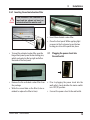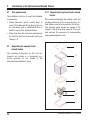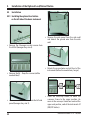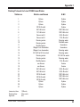
1
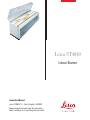
Leica ST4040
Linear Stainer
Instruction Manual
Leica ST4040 V1.4 - Rev A, English – 06/2009
Always keep this manual near the instrument.
Read carefully prior to operating the instrument.
IMPORTANT NOTE
The information, numerical data, notes and value judgments contained in this manual represent the current state of scientific knowledge
and state-of-the-art technology as we understand it following thorough investigation in this
field. We are under no obligation to update the
present manual periodically and on an ongoing
basis according to the latest technical developments, nor to provide our customers with additional copies, updates etc. of this manual.
For erroneous statements, drawings, technical
illustrations etc. contained in this manual we
exclude liability as far as permissible according
to the national legal system applicable in each
individual case. In particular, no liability whatsoever is accepted for any financial loss or consequential damage caused by or related to
compliance with statements or other information in this manual.
Statements, drawings, illustrations and other information as regards contents or technical details of the present manual are not to be considered as warranted characteristics of our prod-
ucts. These are determined only by the contract
provisions agreed between ourselves and our
customers.
Leica reserves the right to change technical
specifications as well as manufacturing processes without prior notice. Only in this way is it
possible to continuously improve the technology and manufacturing techniques used in our
products.
This document is protected under copyright
laws. Any copyrights of this document are retained by Leica Biosystems Nussloch GmbH.
Any reproduction of text and illustrations (or of
any parts thereof) by means of print, photocopy,
microfiche, web cam or other methods – including any electronic systems and media – requires express prior permission in writing by Leica Biosystems Nussloch GmbH.
For the instrument serial number and year of
manufacture, please refer to the name plate at
the back of the instrument.
© Leica Biosystems Nussloch GmbH
Issued by:
Leica Biosystems Nussloch GmbH
Heidelberger Str. 17 - 19
D-69226 Nussloch
Germany
Serial No.: .............. ......................................................
Year of Manufacture: ...............................................
Phone: +49 6224 143-0
Fax:
+49 6224 143-268
Internet: http://www.microsystems.com
Leica ST4040 – Linear Stainer
Country of Origin: Federal Republic of Germany
3
Table of Contents
IMPORTANT NOTE ........................................................................................................................................................................................... 3
1.
1.1
1.2
Important Information .......................................................................................................................................................................... 6
Symbols used in this manual and ....................................................................................................................................................... 6
Designated use ...................................................................................................................................................................................... 7
2.
2.1
2.1.1
2.1.2
2.1.3
Safety ....................................................................................................................................................................................................... 8
Safety instructions ................................................................................................................................................................................ 8
Transport and installation ................................................................................................................................................................... 8
Operating the instrument ..................................................................................................................................................................... 9
Cleaning and maintenance ............................................................................................................................................................... 10
3.
Installation ........................................................................................................................................................................................... 11
3.1
3.2
3.2.1
3.3
3.4
3.4.1
Site requirements ................................................................................................................................................................................ 11
Unpacking the instrument .................................................................................................................................................................. 12
Repacking the instrument ................................................................................................................................................................. 12
Installing the instrument ..................................................................................................................................................................... 13
Standard delivery ‘basic instrument’ and general accessories ................................................................................................. 14
Standard delivery ................................................................................................................................................................................ 14
Basic instrument ST4040 - single load model ................................................................................................................................ 14
Basic instrument ST4040 - double load model (for double row staining) ................................................................................. 14
3.4.2 General accessories .......................................................................................................................................................................... 15
3.5 Electrical connections ........................................................................................................................................................................ 16
3.5.1 Adjusting the voltage selector .......................................................................................................................................................... 16
3.5.2 Connecting the power chord to the ................................................................................................................................................. 17
3.6 Installing the accessories .................................................................................................................................................................. 17
3.6.1 Installing the water inlet hose .......................................................................................................................................................... 17
3.6.2 Installing the drain hose .................................................................................................................................................................... 17
3.6.3 Installing the exhaust air hose ......................................................................................................................................................... 17
3.6.4 ..................................................................................................................................................................... Placing the instrument in its
........................................................................................................................................................................................................................
..................................................................................................................................................................................... permanent position
18
3.6.5 Connecting the inlet hose to the tap ................................................................................................................................................ 18
3.6.6 Leveling the instrument ..................................................................................................................................................................... 18
3.6.7 Inserting the activated carbon filter ................................................................................................................................................ 19
3.7 Plugging the power chord into
...................................................................................................................................................................................................... the wall outlet
19
4.
4.1
4.2
4.2.1
4.3
4.3.1
Installation of the Optional Load/Unload Station ......................................................................................................................... 20
Site requirements ................................................................................................................................................................................ 20
Unpacking the optional load /
unload station ....................................................................................................................... 20
Repacking the optional load / unload
station ...................................................................................................................... 20
Standard delivery and accessories - optional load / unload station .......................................................................................... 21
Standard delivery - optional load station ......................................................................................................................................... 21
Accessories - optional load station ................................................................................................................................................. 21
4.3.2 Standard delivery - optional unload station ................................................................................................................................... 21
4
Instruction Manual V 1.4 – 06/2009
Table of Contents
Accessories - optional unload station ............................................................................................................................................ 21
4.4 Installation ............................................................................................................................................................................................ 22
4.4.1 Installing the optional load station ................................................................................................................................................... 22
4.4.2 Installing the optional unload station ..................................................................................................................................................
on the right of the basic instrument ..................................................................................................................................................... 25
4.5 Changing the guide ramps for slide rack carriers ......................................................................................................................... 28
5.
Instrument Properties ........................................................................................................................................................................ 29
5.1
Technical Data ..................................................................................................................................................................................... 29
6.
Operation .............................................................................................................................................................................................. 30
6.1 Setting up the instrument ................................................................................................................................................................... 30
6.2 Preparing the instrument for staining: inserting and filling the stations .................................................................................... 30
6.3 Staining in two rows ........................................................................................................................................................................... 31
6.3.1 Doubling the specimen throughput ................................................................................................................................................. 31
6.3.2 Carrying out two different, but matching, staining protocols simultaneously ......................................................................... 31
6.3.3 Carrying out two different staining protocols (two subsequent single loads) ......................................................................... 31
6.4 Control panel functions ...................................................................................................................................................................... 32
6.5 Switching on mains and selecting direction of travel and alarm volume .................................................................................. 33
........................................................................................................................................................................................................................... 33
6.5.1 Selecting direction of travel .............................................................................................................................................................. 33
........................................................................................................................................................................................................................... 33
6.5.2 Selecting alarm volume ..................................................................................................................................................................... 34
........................................................................................................................................................................................................................... 34
6.6 Switching on mains without selecting direction of travel/alarm volume .................................................................................. 34
........................................................................................................................................................................................................................... 34
6.6.1 Stand-by mode .................................................................................................................................................................................... 34
........................................................................................................................................................................................................................... 34
6.7 Programming ........................................................................................................................................................................................ 35
6.8 Staining ................................................................................................................................................................................................. 36
6.8.1 Selecting a program ........................................................................................................................................................................... 36
........................................................................................................................................................................................................................... 36
6.8.2 Preparing and inserting the slide racks .......................................................................................................................................... 37
6.8.3 Starting the selected program .......................................................................................................................................................... 38
........................................................................................................................................................................................................................... 38
6.9 Removing the slide racks ................................................................................................................................................................... 39
6.8.4 Interrupting a program ....................................................................................................................................................................... 39
........................................................................................................................................................................................................................... 39
6.9.1 Removing the last slide rack ............................................................................................................................................................. 40
........................................................................................................................................................................................................................... 40
6.10 Removing the slide racks in instruments equipped with optional unload station ................................................................... 40
........................................................................................................................................................................................................................... 40
6.11 Finishing work ..................................................................................................................................................................................... 41
........................................................................................................................................................................................................................... 41
7.
Trouble Shooting ................................................................................................................................................................................. 42
8.
8.1
8.2
Cleaning and Maintenance .............................................................................................................................................................. 44
Cleaning ................................................................................................................................................................................................ 44
Maintenance ........................................................................................................................................................................................ 46
9.
Warranty and Service ........................................................................................................................................................................ 47
Leica ST4040 – Linear Stainer
5
1.
Important Information
The instruction manual for the Leica
ST4040 includes chapters on the following
subjects:
Chapter 1
Chapter 2
Chapter 3
Chapter 4
Chapter 5
Chapter 6
Chapter 7
Chapter 8
Chapter 9
Chapter 10
Appendix 1
6
Structure of this manual
• Table of contents
• Important information on this
manual
Safety
• Read this chapter before
operating the instrument
Installation
• Unpacking and installation
• Standard delivery, accessory
range
Installation
Optional load / unload station
• Unpacking and installation
• Standard delivery, accessory
range
Instrument features
• Technical data
Operation
• Controls
• Setup and daily use
Trouble Shooting
• Operating errors
• Trouble shooting
Cleaning and Maintenance
Warranty and Service
EC Declaration of Conformity
Staining protocols Leica ST4040
1.1
Symbols used in this manual and
their meaning
Warnings appear in a grey box and are
marked by a warning
triangle.
Notes
i.e. important user information appear
in a grey box and are marked by an information
symbol.
(5)
(Fig. 5)
Figures in brackets refer to item numbers in drawings or to the drawing itself.
Instrument type:
All information given in this instruction manual
applies only to the instrument type indicated on
the title page.
A name plate indicating the instrument serial
number is attached to the back of the instrument.
Required information for all enquiries:
For any enquiries please specify:
• Instrument type
• Serial number
Instruction Manual V1.4 – 06/2009
1.
Important Information
General
1.2
This instruction manual includes important instructions and information related to the operating safety and maintenance of the instrument.
The instruction manual is an important part of
the product. It must be read carefully before
first using the instrument and must always be
kept with the instrument.
The Leica ST4040 is an automated linear stainer
for the preparation of histological and cytological routine stainings.
It is designed for use in pathology laboratories,
and only for performing the following tasks:
It will be necessary to add appropriate instructions to this instruction manual, if imposed by
existing national regulations or by laws on accident prevention and environmental protection in
the country of the operating authority.
Designated use
• Staining of thin sections of tissue specimens
or of cytological samples, attached to microscope slides
Any use of the instrument other than its designated use is considered improper.
Read this instruction manual carefully before
attempting to use or operate the instrument.
Please pay particular attention to the
safety instructions in chapter 2. Please
do read this information, even if you
are familiar with the operation and use
of Leica products.
Leica ST4040 – Linear Stainer
7
2.
Safety
2.1
Safety instructions
This instrument has been built and tested in accordance with the following safety regulations
on electrical measuring, control, regulating and
laboratory devices.
In order to maintain this condition and to ensure
safe operation, the operator must observe the
instructions and warnings contained in this instruction manual.
For current information about applicable standards, please refer to the CE declaration of conformity on our Internet site:
www.histo-solutions.com
2.1.1 Transport and installation
• Do not operate the instrument in rooms
where risk of explosion exists!
• Do not expose the instrument to direct sunlight (windows)!
• Do not install the instrument above a heater!
• Install the instrument on an even laboratory
bench which must be absolutely level!
• Two people are needed to lift / carry the instrument!
• Before connecting the instrument to mains,
make sure the correct voltage setting,
matching the nominal voltage at the site of
installation, has been selected!
• Upon installing the drain hose make sure
there is a gradient from the drain outlet to
the waste pipe.
• To protect the user from hazardous solvent
fumes, make sure to operate the instrument
either with the activated carbon filter or the
exhaust air hose!
8
Instruction Manual V1.4 – 06/2009
2.
Safety
2.1.2 Operating the instrument
• The instrument may only be operated by
skilled personnel. It may only be operated
according to its designated use and in accordance with the instructions given in this
manual!
• If not only the water tap but also the ball
valve has been closed (--> e.g. when setting
up the instrument), the tap water flow rate
has to be adjusted when starting a program
(see also chapters 3.6 and 6.8.3).
• While working with reagents (filling / emp-tying the reagent stations, working on the instrument while the lid/s is/are open) appropriate protective gear (lab coat, gloves, safety goggles) must be worn!
• The flow rate must not be too fast, to en-sure
that the specimens remain firmly at-tached
to the slide surface!
• Make sure to operate the instrument ei-ther
with the activated carbon filter or with the
exhaust air hose (--> Chapter 3.6, ‘Installing
the accessories’). Even when the instrument
is operated according to its designated use,
hazardous solvent fumes develop, which are
damaging to the operator’s health and do
also pose a risk of fire!
• Risk of fire, when working with an open
flame (Bunsen burner) immediately next to
the instrument (solvent fumes)! - Therefore,
keep a safety distance of 1 meter!
• If a staining program is to be interrupted for
an extended period of time, do not leave any
slide racks in the tap water sta-tions, in order
to prevent them from drying out!
• As soon as the alarm is triggered, immediately remove the completed slide rack from the
last station or from the unload container of
the optional unload station! Otherwise, immersion times for the remaining slide racks
will be prolonged!
• In case of emergency switch off mains and
unplug the power chord!
• If ‘Alarm off’ is selected (not recommended!), the instrument must be observed constantly, to make sure all slide racks are removed immediately when reaching the last
station!
Leica ST4040 – Linear Stainer
9
2.
Safety
2.1.3 Cleaning and maintenance
• Only technical service engineers authorized
by Leica may access the internal components of the instrument for service and repair.
Exception: Changing the activated carbon filter is the only maintenance task to be carried out by the user.
• Prior to cleaning the instrument, always
switch off mains and unplug the power
chord!
• Dispose of used reagents according to the
laboratory regulations in force in your country!
• Spilled solvents (reagents) have to be wiped
away immediately! - In case of long-term exposure, the lid surfaces are only conditionally resistant to solvents!
• When handling cleaning detergents, follow
the instructions of the manufacturer and
make sure all applicable laboratory regulations are complied with!
• When cleaning the instrument, no liquid may
enter in contact with any of the electrical
connections or get into the interior of the instrument!
• Wash the tap water and reagent stations in
the dishwasher at a temperature of max. +65
°C. - Use a standard detergent for laboratory
dishwashers.
At any rate avoid washing the stations at
higher temperatures (e. g. in industrial diswashers which run at a temperature of
+85 °C), as the stations may become deformed!
• The painted surfaces and the control panel
are not resistant to xylene or acetone!
• For cleaning the instrument, do not use any
one of the following: alcohol, detergents
containing alcohol (window cleaner!), abrasive cleaning powders, solvents containing
xylene or acetone!
• To clean the lids, control panel and housing,
use mild household detergents; - see safety
instruction above for non-appropriate ingredients!
10
Instruction Manual V1.4 – 06/2009
3.
3.1
Installation
Site requirements
The installation site has to meet the following
requirements:
• Stable laboratory bench, exactly level, at
least 1.60 m wide and 60 cm deep.
• Tap water supply at a distance of max. 2 m
and drain at a distance of max. 1.50 m from
the corresponding inlet and outlet at the
back of the instrument.
Do not operate the instrument in rooms
where risk of explosion exists!
Do not expose the instrument to direct
sunlight (windows)!
Do not install the instrument above a
heater!
- Please bear in mind: The connections are
located at the extreme left on the back of the
instrument.
• Fume hood at a distance of max. 3.50 m from
the instrument, if the instrument is to be operated with the exhaust air hose (otherwise
the instrument must be operated with the
activated carbon filter)!
• Vibration-free floor.
• Sufficient open space (70 cm) above the laboratory bench, to ensure trouble-free opening of the lids.
• Stable ambient temperature of +10 °C to +35
°C.
• Relative air humidity of maximum 80%, noncondensing.
• No other instruments which cause vibrations installed nearby.
Leica ST4040 – Linear Stainer
11
3.
Installation
3.2
Unpacking the instrument
The unpacking instructions for all Leica instruments are located in a transparent protective envelope on the outside of the instrument transportation crates.
3.2.1 Repacking the instrument
We recommend keeping the original crate and
packing material in store, in case the instrument needs to be repacked in the future.
The drawing below shows the design of the
original crate and packing material. The numbers indicate the sequence of disassembling
and reassembling the crate.
9
8
7
6
5
4
3
2
1
12
Instruction Manual V1.4 – 06/2009
3.
3.3
Installation
Installing the instrument
• To lift, grip the instrument by the transport
handles.
Two people are needed to lift / carry
the instrument, since it weighs 73 kg
(see ‘Technical data’, chapter 5.1)!
• Install the instrument on the designated
bench.
• Unscrew the transport handles.
• Remove the plastic protective cover from the
instrument.
• Check all delivered parts against the packing
list to verify whether the delivery is complete
- see chapter 3.4 ‘Standard delivery ‘basic
instrument’ and general accessories’).
• For all further installation steps, see chapters 3.5 ‘Electrical connection’ and 3.6 ‘Installing the accessories’.
Leica ST4040 – Linear Stainer
13
3.
Installation
3.4
Standard delivery ‘basic instrument’ and general accessories
3.4.1 Standard delivery
Basic instrument ST4040 - single load model
•
•
•
•
•
•
•
•
•
•
•
•
Basic instrument with three-piece lid
27 Reagent stations, plastic
4 tap water stations, complete assy. with inlet valve
1 Drain hose for waste water, 2 m long
1 Tap water inlet hose, 2.50 m long,
complete with 3/4“ connection for water tap and replacement gasket
2 Lids for reagent stations
1 Cover for second row
1 Instruction manual ................................................................ 14 0474 80001
1 Tool set, including:
• 1 Single-ended open-jaw wrench, size 27
• 1 Single-ended open-jaw wrench, size 13
• 1 Screw driver, 5.5 x 200 mm
• 1 Screw driver, 3 x 50 mm
1 Water tap adapter for 1/2“ water taps
3 Disposable plastic films, solvent-resistant, for control panel
1 Set of power chords:
• Euro
• UK
• USA
Basic instrument ST4040 - double load model (for double row staining)
To use a single load model for double row staining, order the appropriate number (may vary - depends on individual staining applications) of the accessories listed below (see chapter 3.4.2 - ‘General
accessories’ for details):
•
•
•
•
•
14
Reagent stations
Tap water stations
Lids for reagent stations
Slide racks
Slide rack carriers
Instruction Manual V 1.4 – 06/2009
3.
Installation
3.4.2 General accessories
•
•
•
•
•
•
•
•
•
•
•
•
•
•
•
•
•
•
•
•
•
Reagent stations, plastic
Tap water stations, complete assy. with inlet valve
Leica slide racks, metal
Sakura slide racks, plastic
Adapter for large slides
Drain hose, 4 m long
Tap water inlet hose, 2.50 m long,
complete with 3/4“ connection for water tap
Lids for reagent stations
Slide rack carriers for Leica slide racks
Slide rack carriers for Medite/Hacker slide racks
Slide rack carriers for Sakura slide racks
Storage container for slide rack carriers, fits on instrument housing
Activated carbon filter
Exhaust air hose, 2 m long
Exhaust air hose, 4 m long
Disposable plastic films, solvent-resistant, for control panel (set of 10)
Optional load station, left*
Optional load station, right*
Optional unload station, left*
Optional unload station, right*
Leica CV5000 adapter for slide racks:
• CV5000 slide rack adapter, removable:
- slides onto Leica slide racks for coverslipping in Leica CV5000.
- up to Leica CV5000 s/nos. ≤ CV026096
• CV5000 stationary slide rack adapter:
- for permanent installation in Leica CV5000 for using Leica
ST4040 slide racks in CV5000.
- starting from Leica CV5000 s/nos. > CV026096)
To order accessories, please contact your Leica local sales organization for the latest literature / current order numbers on the full
range of Leica ST4040 accessories.
*) For accessories for optional load / unload station, please refer to
chapters 4.3.1 and/or 4.3.2 respectively!
Leica ST4040 – Linear Stainer
15
3.
Installation
3.5
Electrical connections
• Insert
the
small
screwdriver (3 x 50 mm)
into the notch at the
lower end of the voltage
selector shell. Carefully
release the lock, using
the screwdriver as a le-
3.5.1 Adjusting the voltage selector
The voltage selector is preset to match
the nominal voltage of the country of
delivery.
Nevertheless, it is absolutely necessary that you check the setting of the
voltage selector prior to connecting
the instrument to mains, to make sure
the setting is correct!
Connecting the instrument to mains
with the voltage selector at a wrong
setting can cause severe damage to
the instrument!
ver.
3
2
• Check the setting showing in window (1).
1
• Does it correspond to the nominal voltage in
your laboratory?
• If the setting is correct: --> Go to next page
(chapter 3.5.2).
• If the setting is not correct, the voltage selector must be changed to the correct
setting: --> Continue to follow instructions
on this page.
16
• Remove shell (2) with fuses (3).
• Take the fuses out of the shell.
• Pull the voltage selector out of the shell and
reinsert it such that the desired setting is
visible in the small window (1) of the shell.
• Reinsert the shell together with voltage selector and fuses into the corresponding
opening at the back of the instrument and
apply light pressure until it locks.
1
• Double-check if the correct setting now
shows in window (1).
Instruction Manual V1.4 – 06/2009
3.
3.5.2 Connecting the power chord to the
instrument
• Remove the adhesive tape from the mains
inlet.
3.6
Installation
Installing the accessories
3.6.1 Installing the water inlet hose
• Install the inlet hose, which supplies water
to the tap water stations.
3.6.2 Installing the drain hose
• Select the appropriate power chord (the instrument is delivered with several, countryspecific power chords) and connect it to the
mains inlet at the rear of the instrument.
• Do not yet plug the power chord into the wall
outlet.
• Connect the drain hose.
Upon installing the drain hose make
sure there is a gradient from the drain
outlet to the waste pipe.
3.6.3 Installing the exhaust air hose
• The unload sensor port remains empty; unless the instrument is operated with optional
unload station (see Chapter 4).
Leica ST4040 – Linear Stainer
• Connect the exhaust air hose (optional!).
The instrument may be operated either with the exhaust air hose or
with the activated carbon filter.
17
3.
Installation
3.6.4 Placing the instrument in its
permanent position
• Place the instrument in its permanent position on the laboratory bench.
• Connect the exhaust air hose to the fume
hood, or lead outside.
• Insert drain hose into drain.
3.6.5 Connecting the inlet hose to the tap
• Connecting to 3/4“ water tap:
Connect the ball valve to the water tap and
attach the tap water inlet hose to the ball
valve.
Ball valve closed.
• Do not yet open neither water tap nor ball
valve (see above)!
When setting up the instrument, an adjustment of the tap water flow rate has
to be done. This adjustment cannot be
done until after the tap water stations
have been inserted. - For detailed instructions on the flow rate adjustment,
see Chapter 6.8.3!
For safety reasons, we recommend using a so-called ‘Aquastop’ device, as
commonly used with household appliances.
3.6.6 Leveling the instrument
When installed in its final posi-tion on
the laboratory bench, the instrument
must be exactly level! (see also chapter 3.1 ‘Site requirements’).
• Connecting to 1/2“ water tap:
Fit the adapter in between water tap and
ball valve.
18
• If necessary, the instrument can be slightly
readjusted via the adjustable instrument
feet.
• For that purpose, screw the instrument feet
in or out, as needed, until the instrument is
positioned horizontally.
Instruction Manual V1.4 – 06/2009
3.
Installation
3.6.7 Inserting the activated carbon filter
If the instrument is not connected to a
fume hood (via exhaust air hose), an
activated carbon filter must be used!
• Insert the activated carbon filter.
• Close the front panel. While applying light
pressure to the front panel, press the two
locking pins to lock the panel into place.
• To insert the activated carbon filter, open the
hinged front panel: press the two locking pins,
which are located on the top right and left on
the inside of the front panel.
3.7
• Remove the the activated carbon filter from
the package.
• Prior to plugging the power chord into the
wall outlet, check whether the mains switch
is in OFF (‘0’) position.
• Write the current date on the filter (to be reminded to replace the filter in time).
Leica ST4040 – Linear Stainer
Plugging the power chord into
the wall outlet
• Connect the power chord to the wall outlet.
19
4.
Installation of the Optional Load/Unload Station
4.1
Site requirements
The installation site has to meet the following
requirements:
• Stable laboratory bench, exactly level, at
least 1.60 m wide and 60 cm deep for the basic instrument, plus an additional 0.30 m of
width for each of the optional stations.
• Other than that, the same site requirements
as listed for the basic instrument apply (see
Chapter 3.1).
4.2
Unpacking the optional load /
unload station
The unpacking instructions for all Leica instruments are located in a transparent protective envelope on the outside of the
instrument transportation crates.
4.2.1 Repacking the optional load / unload
station
We recommend keeping the original crates and
packing material in store, in case the load / unload stations need to be repacked in the future.
The drawing below shows the design of the
original crate and packing material. The numbers indicate the sequence of disassembling
and reassembling the crate.
7
6
5
4
3
2
1
20
Instruction Manual V1.4 – 06/2009
4.
4.3
Installation of the Optional Load/Unload Station
Standard delivery and accessories - optional load / unload station
4.3.1 Standard delivery - optional load station
•
•
•
•
1 Optional load station
5 Reagent stations
1 lid for reagent stations of optional load station
1 Tool set, including:
• 1 Hexagon key, size 2.5
• 1 Hexagon key, size 3
• 1 Hexagon key, size 4
• 1 Ring wrench, size 10
Accessories - optional load station
• Reagent stations
• Lid for reagent stations of optional load station
4.3.2 Standard delivery - optional unload station
•
•
•
•
•
1 Optional unload station
1 Unload container for optional unload station
1 Lid for unload container of optional unload station
1 Connecting cable for unload sensor
1 Pair of guide ramps no. 2, for slide racks / slide rack carriers
by Medite/Hacker and/or Sakura
• 1 Tool set, including:
• 1 Hexagon key, size 1.5
• 1 Hexagon key, size 2.5
• 1 Hexagon key, size 3
• 1 Hexagon key, size 4
• 1 Ring wrench, size 10
Accessories - optional unload station
• Unload container for optional unload station*
• Lid for unload container of optional unload station
For double loading (staining in two rows) with optional load and/or
unload station attached to the basic instrument, order the necessary
accessories for the optional load and/or unload station as needed.
*) Can also be used for intermediate storage of slide racks prior to
coverslipping; (see chapter 6.10 for details).
Leica ST4040 – Linear Stainer
21
4.
Installation of the Optional Load/Unload Station
4.4
Installation
4.4.1 Installing the optional load station
on the left side of the basic instrument
• Remove the side panel from the side wall
and detach the ground wire from the side
wall.
• Remove the 4 hexagon socket screws from
the left lid (hexagon key, size 4).
• Detach the ground wire and pull it out of the
instrument (will not be needed any longer.)
• Remove the lid. - Keep the screws (will be
needed later)!
• Remove the 2 black screws from the left side
panel (hexagon key, size 3).
22
• Press the Start/Stop button, to move the
conveyor frame to the upper position. As
soon as the conveyor frame has reached the
upper end position, switch the instrument off
(ON/OFF button).
Instruction Manual V1.4 – 06/2009
4.
Installation of the Optional Load/Unload Station
1
• Place the optional load station on the left
side of the basic instrument.
• Plate (1) which connects optional load station
and basic instument is fastened with two Allan screws.
In order to establish safe protective
grounding, it is essential to fasten plate
(1) securely.
• Move the optional load station right up to the
instrument, inserting the two pins, located
on the left and right at the bottom of the optional load station, into the corresponding
openings in the basic instrument.
• Open the Lid
• Tighten the screw on the left wall of the optional load station ring wrench, size10).
Leica ST4040 – Linear Stainer
• Pull the conveyor frame of the optional load
station upwards using both your hands.
23
4.
Installation of the Optional Load/Unload Station
• Fit the connecting plates attached to the
front and rear half of the conveyor frame of
the optional load station over the insides of
the front and rear half of conveyor frame of
the basic instrument.
• Lower the conveyor frame (now connected
to one single piece) pushing the ON/OFF button.
• Use the 4 hexagon socket screws which you
have kept (see step 1) to attach the lid of the
optional load station to the corresponding
hinge (= left hinge of basic instrument).
• Bolt the two front halves of the conveyor
frames together with two hexagon socket
screws (hexagon key, size 2.5).
To install an optional load station to
the right side of the basic instrument,
follow the same steps - carried out laterally reversed.
• Bolt the two rear halves of the conveyor
frames together with two hexagon socket
screws (hexagon key, size 2.5).
24
Instruction Manual V1.4 – 06/2009
4.
Installation of the Optional Load/Unload Station
4.4.2 Installing the optional unload station
on the right of the basic instrument
• Remove the 4 hexagon socket screws from
the right lid (hexagon key, size 4).
• Remove the lid. - Keep the screws (will be
needed later)!
• Remove the 2 black screws from the right
side panel (hexagon key, size 3).
Leica ST4040 – Linear Stainer
• Remove the side panel from the side wall
and detach the ground wire from the side
wall.
• Detach the ground wire and pull it out of the
instrument (will not be needed any longer.)
• Press the Start/Stop button, to move the
conveyor frame to the upper position. As
soon as the conveyor frame has reached the
upper end position, switch the instrument off
(ON/OFF button).
25
4.
Installation of the Optional Load/Unload Station
In order to establish safe protective
grounding, it is essential to fasten
plate (1) securely.
• Place the optional unload station on the right
side of the instrument.
• Move the optional unload station right up to
the instrument, inserting the two pins, located on the left and right at the bottom of the
optional load station, into the corresponding
openings in the basic instrument.
• Open the right lid.
• Tighten the screw on the right wall of the optional unload station (ring wrench, size10).
1
• Plate (1) which connects optional unload
station and basic instument is fastened with
two Allan screws.
26
• Pull the conveyor frame of the optional unload station upwards using both your hands.
• Fit the connecting plates attached to the
front and rear half of the conveyor frame of
the optional unload station over the insides
of the front and rear half of the conveyor
frame of the basic instrument.
Instruction Manual V1.4 – 06/2009
4.
Installation of the Optional Load/Unload Station
• Bolt the two front halves of the conveyor
frames together with two hexagon socket
screws (hexagon key, size 2.5).
• Use the 4 hexagon socket screws which you
have kept (see step 1) to attach the lid of the
optional unload station to the corresponding
hinge (= right hinge on basic instrument).
• Bolt the two rear halves of the conveyor
frames together with two hexagon socket
screws (hexagon key, size 2.5).
• Insert the plug of the unload sensor cable
into the unload sensor port on the rear of the
basic instrument.
• Lower the conveyor frame (now connected
to one single piece) pushing the ON/OFF
button.
Leica ST4040 – Linear Stainer
To install an optional unload station on
the left side of the basic instrument,
follow the same steps - carried out laterally reversed.
27
4.
Installation of the Optional Load/Unload Station
4.5
Changing the guide ramps for slide rack carriers
To operate the instrument with Medite
/ Hacker or Sakura slide racks, the
standard guide ramps no. 1 for Leica
slide racks must be exchanged for
guide ramps no. 2 (see ‘Standard delivery - optional unload station’, chapter
4.3.2).
2
2
1
2
1
• Place grooved ramp no. 2 onto the rear pin
and use the hexagon key, size 1.5 to fasten
the two grub screws in the ramp (clockwise
rotation through about 180 °).
1
• Use the hexagon key, size 1.5 to unscrew
both ramps no. 1 loosening the two corresponding grub screws in each ramp (counterclockwise rotation through about 180 °).
Remove both ramps.
28
• Place plain ramp no. 2 onto the front pin and
fasten the front ramp (clockwise rotation of
both grub screws through about 180 ° hexagon key, size 1.5).
Store ramps no. 1 for future use!
Instruction Manual V1.4 – 06/2009
5.
5.1
Instrument Properties
Technical Data
General
Admissions:
Nominal supply voltage:
VDE, UL, cUL, C-Tick Label
available: 100 V AC ± 10 %
120 V AC ± 10 %
230 V AC ± 10 %
240 V AC ± 10 %
Nominal frequency:
50/60 Hz
Maximum power draw:
150 VA
1
I
Protective class :
Mains fuses:
Circuit breaker manufactured by ETA, 2 A
model: 3120-F421-P7T1-W01D-2 A
Primary fuses: manufactured by Schurter: model Fst
2 x T8 A
Secondary fuses: manufactured by Schurter: model Fst
Motor (F1) T 600 mA
Electronic (F2) T 1,6 A
1
2
Pollution degree :
Overvoltage installation category:
II
Working temperature range: +10 °C to +35 °C
Relative air humidity:
Sound intensity level:
1)
max. 80 %, non-condensing
< 70 dB
according to IEC-1010, UL 3101, EN 61010
Dimensions and weight
Basic instrument (W x H x D):
Basic instrument with optional load and unload station (W x H x D):
Optional load / unload station (W x H x D):
Working height: 318 mm
Weight:
(Basic instrument with accessories)
(optional load station)
(optional unload station)
Leica ST4040 – Linear Stainer
1,435 x 444 x 436 mm
1,969 x 444 x 436 mm
267 x 444 x 392 mm
73 kg
16 kg
14 kg
29
6.
Operation
6.1
Setting up the instrument
To set up the instrument follow all instructions of chapter 6 step by
step.
6.2
Preparing the instrument for staining: inserting and filling the stations
• Select a staining protocol.
(For examples, see Appendix 1: ‘Staining protocols’)
• According to the selected staining protocol, determine the order of reagent and tap water stations.
• Open all three lids.
The Leica ST4040 is equipped with a three-piece lid, thus e n abling the operator to open just one of the two small lids on the right
or left of the instrument for loading / unloading slide racks. This system keeps the exposure of laboratory personnel to hazardous fumes
to a minimum.
• Remove the cover screws from those positions where you have decided to install tap water stations (tap water stations can be installed from
positions 3 through 20).
• Insert the tap water stations (yellow - see left) and the reagent stations
(white).
• Make sure that all stations are inserted correctly; the stations must not
be jammed (overlapping rims!).
• Add reagents according to selected staining protocol. - Do not exceed
the maximum volume or remain under the minimum volume!
• Close the lid entirely.
30
Instruction Manual V 1.4 – 06/2009
6.
6.3
Operation
Staining in two rows
6.3.1 Doubling the specimen throughput
• For this type of application, the sequences of reagent / tap water stations in rows 1 and 2 must be identical.
• According to the station sequence selected for row 1 (see Chapter 6.2)
insert an identical sequence in row 2.
• Both rows are run with the same program.
6.3.2 Carrying out two different, but matching, staining protocols simultaneously
• Precondition: the program parameters of both protocols must be the
same (i.e. both rows are run with the same program).
• The two staining protocols are coordinated through the number of reagent stations and/or the concentration or dilution of the reagents (for
details, see Appendix 1 - ‘Staining protocols’).
Important note to chapters 6.3.1 and 6.3.2
• When staining in two rows, standard slide rack carriers, as for single
row staining, are used.
• Slide rack carriers located side by side in rows 1 and 2 are inserted
laterally reversed into the same notch of the conveyor frame (see left).
6.3.3 Carrying out two different staining protocols (two subsequent single loads)
• The two rows are never carried out simultaneously, i.e.: row 1 is run
with program 1 - row 2 with program 2, or vice versa.
In 6.3.3 the advantage of staining in two rows is that 2 different staining protocols, though not
run simultaneously, can be run one directly after another without any delay; whereas in a single load model, stations would have to be rearranged, refilled etc. prior to being able to run the
second protocol.
Leica ST4040 – Linear Stainer
31
6.
Operation
6.4
Control panel functions
IMMERSION TIME
button Display / select immersion time
DISPLAY
SCREENDisplay immersion
and draining times
DRAINING TIME
button Display / select
draining time
AGITATION button Agitation (dips)
ON/OFF
PROGRAM 1 button Select / program
program no. 1
+/- buttons Change displayed
parameters
32
ON/OFF button switch on instrument
--> stand-by mode
MAINS SWITCH connects / disconnects
instrument to /
from mains
(0 = OFF / I = ON)
START/ STOP button Start / stop
staining programs
PROGRAM 2 button Select / program
program no. 2
Instruction Manual V 1.4 – 06/2009
6.
6.5
Operation
Switching on mains and selecting direction of travel and alarm volume
• Switch on mains (O = OFF / I = ON).
• The current software version is displayed, in 4 digits, for 10 seconds.
• Only during this phase can the direction of travel and the alarm volume be selected and/or changed!
• If direction of travel and/or alarm volume have already been selected
and you do not want to make any changes to those parameters either: -> go on to Chapter 6.6.
6.5.1 Selecting direction of travel
• Press Start/Stop and hold.
• Depending on the desired direction of travel press the ‘+’ or ‘-’ button:
• Pressing the ‘+’ button:
• Right half of display screen (= indication of seconds) lights up:
--> Direction of travel to the right (= staining starts from the left).
• Pressing the ‘-’ button:
• Left half of display screen (= indication of minutes) lights up:
--> Direction of travel to the left (= staining starts from the right).
Leica ST4040 – Linear Stainer
33
6.
Operation
6.5.2 Selecting alarm volume
• Press the ‘Immersion time’ button and hold.
• Press ‘+’ or ‘-’ respectively:
• Each time when pressing a button, the volume changes audibly:
• Alarm OFF --> Alarm low --> Alarm loud.
If ‘Alarm OFF’ is selected (not recommended!), the instrument must be
observed constantly, to make sure all slide racks are removed immediately when reaching the last station!
• Proceed to --> 6.6.1 ‘Standby mode’.
6.6
Switching on mains without selecting direction of travel/alarm volume
• Switch on mains (O = OFF / I = ON).
• The current software version is displayed for 10 seconds.
• If no further buttons are pressed during this phase, after 10 seconds the LED of the ON/OFF button lights up.
6.6.1 Stand-by mode
• Press ‘ON/OFF’ button.
• The fan goes on.
• The LED (in the program button) of the program used last lights up
(here: ‘Prog 1’) and the programmed parameters are displayed.
• Exception:
Prior to switching off the mains a program had not yet been fini-shed
or a power failure occurred while a program was in progress:
• In those cases the instrument does not switch to the stand-by
mode but continues the previously interrupted program.
34
Instruction Manual V 1.4 – 06/2009
6.
6.7
Operation
Programming
Programming must be done while in stand-by mode. The instrument
can store 2 programs: (buttons ‘Prog 1’ and ‘Prog 2’).
• Select a program (‘Prog 1’ or ‘Prog 2’).
• Press the desired button (here ‘Prog 1’) and hold for approx. 5 seconds
- until the LED in the button starts flashing.
• Press the ‘Immersion time’ button:
• The LED in the button lights up.
• Use the ‘+/-’ buttons to select the desired value.
• Immersion time can be set from 0 seconds up to 99 minutes, 59 seconds.
• To set the time, the button can be pressed and released - going up or
down step by step - or it can be pressed and held. If the button is pressed and held, the display scrolls faster.
• Press the ‘Draining time’ button:
• The LED in the button lights up.
• Use the ‘+/-’ buttons to select the desired value.
Leica ST4040 – Linear Stainer
35
6.
Operation
• Draining time can be set from 0 seconds to 60 seconds.
• Press the agitation button to activate or deactivate ‘Agitation’.
• (LED illuminated = ‘Agitation’ activated).
• (LED not illuminated = ‘Agitation’ deactivated).
• Briefly press the same program button that was selected when you
startled programming (here ‘Prog 1’), until the LED in the button
lights up.
• The programmed parameters are stored.
• To select and store parameters for program 2, proceed in identical
fashion.
6.8
Staining
6.8.1 Selecting a program
• Select the desired program by pressing button ‘Prog 1’ or ‘Prog 2’.
• Program selection is only possible in stand-by mode.
• LED in the program button lights up
--> Program (here ‘Prog 1’) is selected.
36
Instruction Manual V 1.4 – 06/2009
6.
Operation
6.8.2 Preparing and inserting the slide racks
• Insert the slides into the slide rack/s.
• Attach the slide rack carrier to the slide rack/s.
In addition to using Leica slide racks the Leica ST4040 can also be
run with Medite/Hacker and/or Sakura slide racks. For that purpose, the matching slide rack carriers for those brands have to be
ordered (see chapter 3.4.2 ‘General accessories’).
• Open the loading zone lid.
• Insert the first slide racks into the first stations of the loading zone.
• Insert the slide rack carriers with the attached slide racks into the
center of the stations. Use the notches in the conveyor frame as
orientation help.
• When operating the instrument with optional load / unload sta-tion,
insert the slide rack carriers into the reagent stations of the optional load station.
• When staining in two rows, insert the slide racks into the stations of
the loading zone as shown.
• When staining in two rows with optional load / unload station attached to the basic instrument, insert the slide rack carriers into
the reagent stations of the optional load station.
• To stain large slides individually, use the ‘adapter for large slides’.
Leica ST4040 – Linear Stainer
37
6.
Operation
6.8.3 Starting the selected program
• With the lid closed, open the ball valve and, if closed as well, open the
water tap.
If not only the ball valve but also the water tap has been closed (-->
e.g. when setting up the instrument), the tap water flow rate has to be
adjusted when starting a program (see also chapter 3.6).
Ball valve closed
• For that purpose, press the Start/Stop button:
• The water supply valves are opened.
• The processing mechanism starts.
• Via the ball valve (slowly open or close further) select the appropriate
tap water flow rate (look at the tap water station - see which quantity of
flow looks appropriate).
• The water has to rise inside the tap water station and the water flow
has to be strong enough to wash surplus staining matter from the
specimens.
Ball valve open
However, the flow rate must not be too fast, to ensure that the specimens remain firmly attached to the slide surface!
The ball valve is used to adjust the optimum water flow rate with the
water tap fully open.
If there is no significant water pressure variation in your lab and as
long as the number of tap water stations remains unchanged, the setting of the ball valve should not be altered. To start / end your daily
routine, simply open / close the water tap.
38
Instruction Manual V 1.4 – 06/2009
6.
Operation
6.8.4 Interrupting a program
• If necessary, a staining program can be interrupted pressing the Start/
Stop button.
The Leica ST4040 has a water saving function:
• If a program is interrupted (Start/Stop button),
the water supply to the tap water stations is automatically inter
rupted.
• The remaining water in the tap water stations slowly drains
away through a small opening in the bottom of the station.
• As soon as Start/Stop is pressed again, the program
continues and the water supply to the tap water stations is re
stored.
If a staining program is to be interrupted for an extended period of
time, do not leave any slide racks in the tap water stations, in order
to prevent them from drying out!
• Press Start/Stop again to continue the staining program.
6.9
Removing the slide racks
As soon as the alarm is triggered, immediately remove the completed
slide rack from the last station or from the unload container of the optional unload station! Otherwise, immersion times for the remaining
slide racks will be prolonged!
• The Leica ST4040 is equipped with 2 unload sensors (1 sensor for
each direction of travel), located next to the outer container at each
end of one row.
Leica ST4040 – Linear Stainer
39
6.
Operation
• When the alarm is triggered, immediately open the unloading zone lid
and take out the slide rack.
• As soon as the slide rack has been removed, the program continues.
• Close the unloading zone lid.
6.9.1 Removing the last slide rack
• First remove the slide rack.
• Then, with the conveyor frame in the lowest position, press Start/Stop.
• This ends the program and shuts off the water valves.
6.10 Removing the slide racks in instruments equipped with optional unload station
• To remove the slide racks, proceed as described above (‘alarm is triggered - remove the racks’).
• Instruments equipped with optional unload station allow considerably
more time before the slide racks have to be removed.
The unload station can hold 6 slide racks, i.e., immediate rack removal
is necessary only with every 6th rack.
As long as a slide rack carrier is located on the red ramps, the instrument will not resume processing, i.e. should you decide to remove
only some of the completed slide racks from the optional unload station, at any rate make sure to clear the red ramps!
Outside the instrument, the unload container with the corresponding
lid (see picture left) can be used for intermediate storage of slide
rack carriers prior to cover-slipping (see accessory list in chapter
4.3.2).
40
Instruction Manual V 1.4 – 06/2009
6.
6.11
Operation
Finishing work
• Once the last slide rack is removed, press ‘Start/Stop’.
• Close the ball valve.
Do not change the setting of the water tap, so that the adjusted tap
water flow rate remains unaltered!
• If necessary, add or exchange reagents.
.
• Cover the stations with the station lids.
• Close the lids.
• Leave the fan on, i.e.:
• Do not switch off the instrument via the ‘ON/OFF’ button or via the
mains switch.
Leica ST4040 – Linear Stainer
41
7.
Trouble Shooting
Problem
Possible cause
What to do
No tap water supply.
- Water tap closed.
- Open water tap.
- Ball valve closed.
- Open ball valve.
- Magnetic valve or magnetic
valve drive defective.
- Call Technical Service.
- In-house plumbing
problem (pipes clogged /
furred).
- Call in-house technical service / plumber.
- Slide racks / slide rack carriers bent out of shape.
- If bent only slightly,
just carefully.
- Slide rack carriers / slide
racks jammed.
- Reinsert correctly.
- Slide racks and/or slide
rack carriers significantly
bent out of shape or welding spots broken.
- Parts not usable any more -> discard.
- Toothed belt torn.
- Call Technical Service.
- Motor or motor drive defective.
- Call Technical Service.
- No or only insufficient gradient of drain hose.
- Install drain hose so there
is a sufficient gradient from
drain outlet on instrument
to drain pipe.
- Drain of trough in basic instrument clogged up.
- Remove station and clean
drain with fine bottle brush
or similar.
Slide racks do not advance
and/or are not lowered into reagent / tap water stations.
Waste water does not drain
away.
42
read-
Instruction Manual V1.4 – 06/2009
7.
Trouble Shooting
Problem
Possible cause
What to do
Waste water does not drain
away.
- Drain hose clogged up
(algae).
- Clean drain hose (see
chapter 8 - ‘Cleaning /Maintenance’) - If necessary, replace drain hose by new
one.
Fan does not work.
- Fan or fan drive defective.
- Call Technical Service.
Controls do not work
(buttons do not respond, no
display indication).
- PCB defective.
- Call Technical Service.
- Contacts loose.
- Call Technical Service.
- Control panel drive defective.
- Call Technical Service.
Leica ST4040 – Linear Stainer
43
8.
Cleaning and Maintenance
8.1
Cleaning
Prior to cleaning the instrument, always switch off mains and unplug
the power chord!
Dispose of used reagents according to the laboratory regulations in
force in your country!
Spilled solvents (reagents) have to be wiped away immediately! - In
case of long-term exposure, the lid surfaces are only conditionally
resistant to solvents!
The painted surfaces and the control panel are not resis-tant to xylene or acetone!
For cleaning the instrument, do not use any one of the following: alcohol, detergents containing alcohol (window cleaner!), abrasive
cleaning powders, solvents containing xylene or acetone!
To clean the lids, control panel and housing, use mild household detergents - see safety instruction above for non-appropriate ingredients.
When handling cleaning detergents, follow the instructions of the
manufacturer and make sure all applicable laboratory regulations
are complied with!
When cleaning the instrument, no liquid may enter in contact with
any of the electrical connections or get into the interior of the instrument!
44
Instruction Manual V 1.4 – 06/2009
8.
8.1
Cleaning and Maintenance
Cleaning
• Clean the reagent and tap water stations as well as the trough which
holds the reagent and tape water stations regularly.
• For that purpose, remove the reagent and tap water stations from the
trough.
• The reagent and tap water stations can be washed in a laboratory
dishwasher.
Wash the tap water and reagent stations in the dishwasher at a temperature of max. +65 °C . - Use a standard detergent for laboratory
dishwashers.
At any rate avoid washing the stations at higher temperatures (e. g.
in industrial diswashers which run at a temperature of +85 °C), as the
stations may become deformed!
• To clean the painted instrument surfaces and the lids, use a mild
household detergent (see safety instructions on previous page for nonappropriate ingredients).
• From time to time check the drain hose for accumulated dirt, especially
algae - clean if necessary.
Leica ST4040 – Linear Stainer
45
8.
Cleaning and Maintenance
8.2
Maintenance
Only authorized Leica technical service engineers may open the instrument for maintenance and repair work.
Exception: Changing the activated carbon filter - this is the only
maintenance task to be carried out by the user!
For your own safety, never try to carry out any repairs yourself!
Any unauthorized repair, whether carried out by the user or any third
party not authorized by Leica will void the guarantee (see also Chapter 9.1 ‘Warranty’).
The Leica ST4040 linear stainer is virtually maintenance-free in operation.
However, to ensure a smooth operation of the instrument over many
years, we recommend the following:
• Have the instrument inspected once per year by a qualified service engineer authorized by Leica.
• Enter into a service contract at the end of the warranty period. For
more information, please contact your local Leica technical service
center.
• Exchange the activated carbon filter regularly and dispose of it according to the applicable laboratory rules in your country.
46
Instruction Manual V 1.4 – 06/2009
9.
Warranty and Service
Warranty
Leica Biosystems Nussloch GmbH guarantees that the contractual product delivered has been subjected to a comprehensive quality control procedure based on the Leica in-house testing standards, and that the product is faultless and complies with all technical specifications and/or
agreed characteristics warranted.
The scope of the warranty is based on the content of the concluded
agreement. The warranty terms of your Leica sales organization or the organization from which you have purchased the contractual product shall
apply exclusively.
Service information
If you require technical service or replacement parts, please contact your
Leica sales representative or dealer who sold the product.
Please provide the following information:
•
•
•
•
Model name and serial number of the instrument.
Location of the instrument and name of the person to contact.
Reason for the service call.
Date of delivery.
Decommissioning and disposal
The instrument or parts of the instrument must be disposed of in compliance with the local laws.
Leica ST4040 – Linear Stainer
47
10.
EC Declaration of Conformity
EC Declaration of Conformity
We herewith declare, in exclusive responsibility, that the
Leica ST4040 – Linear stainer
was developed, designed and manufactured to conform with the
• Directive 2006/95/EC of the European Parliament and of the Council (Low Voltage)
• Directive 2004/108/EC of the European Parliament and of the Council (electromagnetic compatibility)
• Directive 98/79/EC of the European Parliament and of the Council (in-vitro diagnostic medical devices)
The following harmonized standards were applied:
• EN 61010-1: 2001
Safety requirements for electrical equipment for measurement, control and laboratory use
Part 1: General requirements
• EN 61326: 2006
Electrical equipment for measurement, control and laboratory use EMC requirements Part 1: General requirements
• DIN EN 61010-2-101: 2002
Safety requirement for electrical equipment for measurement, control and laboratory use
Part 2-101: Particular requirements for in vitro diagnostic (IVD)
• EN 14971: 2007
Medical devices - Application of risk management to medical devices
• EN 591: 2001
Instruction for use for in vitro diagnostic instruments for professional use
In addition, the following in-house standards were applied:
• DIN EN ISO 9001: 2000.
Quality management systems - Requirements
Leica Biosystems Nussloch GmbH
Heidelberger Str. 17-19
D-69222 Nussloch
May 15, 2008
48
..................................
Anne De Greef-Safft
President Biosystems Devision
Instruction Manual V 1.4 – 06/2009
Appendix 1
Staining Protocols for Leica ST4040 Linear Stainer
Station no.
Elastica van Gieson
H&E
1
2
3
4
5
6
7
8
9
10
11
12
13
14
15
16
17
18
19
20
21
22
23
24
25
26
27
Xylene
Xylene
Xylene
100 % Alcohol
96 % Alcohol
75 % Alcohol
Resorcinol G
Resorcinol G
Running water
Running water
Distilled water
Weigert iron haemalum
Weigert iron haemalum
25 % HCl in 96 % alcohol
Running water
Running water
Distilled water
van Gieson
van Gieson
96 % Alcohol
96 % Alcohol
100 % Alcohol
100 % Alcohol
100 % Alcohol
Xylene
Xylene
Xylene
Xylene
Xylene
Xylene
Xylene
100 % Alcohol
100 % Alcohol
96 % Alcohol
75 % Alcohol
Running water
Distilled water
Haemalum
Haemalum
Running water
Running water
25 % HCl in water
Running water
75 % Alcohol
Eosine
Eosine
96 % Alcohol
96 % Alcohol
100 % Alcohol
100 % Alcohol
100 % Alcohol
Xylene
Xylene
Xylene
Immersion time:
Draining time:
Agitation:
1 Minute
5 Seconds
ON
Leica ST4040 – Linear Stainer
49
Appendix 2
Ordering Information
Lid, cpl. w/handle
Slide rack carrier Leica
Slide rack carrier Medite
Slide rack carrier Sakura
Slide rack cpl.
Sakura slide rack
CV5000 adapter, stationary
CV5000 adapter, removable
Storage container
Activated carbon filter
Suction tube 2m
Suction tube 4m
Tap water station, assy.
Reagent station
Optional load station right
Optional load station left
Optional unload station right
Optional unload station left
Lid for reagent stations, opt . load station
Lid for unload container
Unload container
Tap water inlet hose
Drain hose, 4 m
Adapter for large slides, 50 x 75 mm
Disposable plastic film, for control panel
Power cord Australia
Power cord 'EU'
Power cord 'USA-CAN-J'
Power cord 'UK'
Slow-blowing fuse 6.3x32 T8.0A
Slow-blowing fuse 6.3x32 T0.6A
Slow-blowing fuse T1.6A
50
14 0474 32255
14 0474 32305
14 0474 32258
14 0474 32296
14 0474 32789
14 0474 33463
14 0474 32793
14 0474 32794
14 0474 32261
14 0474 32273
14 0422 31974
14 0422 31975
14 0474 32256
14 0474 32271
14 0474 32241
14 0474 32242
14 0474 32243
14 0474 32244
14 0474 33092
14 0474 33093
14 0474 32363
14 0474 32325
14 0474 33147
14 0456 27069
14 0474 33176
14 0411 32565
14 0411 13558
14 0411 13559
14 0411 27822
14 6943 08001
14 6943 00601
14 6943 01601
Instruction Manual V 1.4 – 06/2009