1
1
Performance Tuning the B Series Engines.
Written by Stephen Strange.
There are few mysteries about the engine employed in the MGB. This is not a state-of-theart, fuel-injected, dual-overhead-camshaft, four-valves-per-cylinder, variable-valve-timing,
microchip-controlled technological wonder, festooned with interconnected sensors and
switches, all linked to mysterious black boxes, and guaranteed to intimidate and befuddle
NASA engineers. This is something more along the order of an archeological relic from a
bygone age of motoring, something that was intended be maintained by its owners with
simple hand tools and to also be produced in versions that were to be installed in farm
tractors and diesel-engined taxis. In today's world of laser weapons, it seems as
anachronistic as a sword. Crude, yet still highly effective in a very intimate way.
Keep in mind that the design of the B Series engine was started in August of 1944 when
it had become obvious that the defeat of Germany was close at hand. Lord Nuffield
gathered together his three top engine designers, Eric Barham, Jimmy Rix, and Bill Appleby
from his engineering staff at the Austin Design Office and gave them the assignment of
creating a pair of all-new engines that would enable the company to get a jump on the
competition in the postwar market. The ultimate result was the A Series and the B Series
engines.
The cast iron block was designed to the British Standard (BS) 1452-17 in which the
coolant jacket extended down to just below the level of the piston rings when the piston was
at Bottom Dead Center (BDC). Flow-cast of grey iron, the block was allowed to slowly cool
so that graphite crystals would form within its matrix, assuring reasonable machinability.
During the era in which the B Series engine was designed, hydraulic tappets for
automotive applications were still in their technological infancy; therefore, the engine was
designed to use solid chilled iron tappets. Setting of valve lash clearances was
accomplished by means of a simple manually adjustable ball end and jam nut mechanism
on the lever end of the rocker arm. The majority of the oil from the rocker arm assembly
was allowed to drain down the pushrod passages in order to lubricate the upper ends of the
tappets and then through two holes respectively positioned in the bottom of the tappet chest
between cylinders #1 & #2 and #3 & #4, thus bypassing the lobes of the camshaft. This
simple approach offered the designers the opportunity to wisely leave the camshaft exposed
to the crankcase so that its lobes could be lubricated by a pressurized spray of oil emitting
from the lower ends of the connecting rods. This desire to lubricate the lobes of the
camshaft and the lower sections of the tappets dictated the thickness of the connecting rod
big end. Adequate bearing support was then achieved by using a large diameter big end
design. The engineers at the factory prudently decided that because the rather stout Renold
camshaft drive chain had an even number (52) of 3/8”pitches (spaces between links), the
sprockets were both given an even number of teeth, 20 for the drive sprocket on the
crankshaft and 40 for the camshaft sprocket. This prevents any single roller of the chain
from contacting the same sprocket tooth each time it makes a consecutive circuit, thus
preventing uneven wear and consequent vibration, as well as prolonging the drive system's
lifespan.
Its Heron-type cylinder head incorporated the pistons into the overall combustion
chamber design by featuring concavities in their crowns. It also made use of Weslakepatented combustion chambers, which were a marked advance beyond previous
technology, allowing for superior air flow characteristics and fuel-air charge distribution while
2
permitting excellent flame propagation. The incoming fuel/air charge was directed toward
the spark plug and away from the hot exhaust valve, minimizing the possibility of preignition
and allowing less ignition advance to be used. The siamesed intake ports, like some other
features of the engine, were largely the result of production economics. By using siamesed
intake ports the intake manifold could be of efficient, yet simple design and thus still be
relatively inexpensive to produce. In addition, the pushrod passages could be neatly
situated between the ports, thus keeping the cylinder head and block as compact and light
as possible. The placement of both the intake and the exhaust manifolds together on the
same side of the cylinder head meant that only one mating surface needed to be machined,
and fewer manifold mounting studs and their attendant threaded bores were required. It
also allowed the distributor, oil filter, and generator to be placed on the opposite side of the
engine for easier accessibility, thus greatly simplifying maintenance.
There are also some distinct engineering advantages to this approach. By placing the
intake ports with their cool incoming fuel/air charge next to the hotter exhaust ports, this
area of the cylinder head is better cooled than it would be in a crossflow design, precluding
warpage by enhancing heat transfer from the exhaust valves and thus extending their lives,
although this configuration allows more heat to accumulate in the walls of the intake ports.
This condition of radiant heat being detrimental to fuel/air charge density, it consequently
reduces power output potential.
Due to the relatively small surface area of the roof of the combustion chamber, the
undersquare (small-bore long-stroke) configuration gives better thermal efficiency and thus
better fuel economy, as well as providing a greater surface area on the exterior of the
cylinder walls in order to minimize the heat transference problems inherent with the cast iron
material that was chosen for the block to be cast of. It also gives better scavenging effect,
thus extending the powerband. By requiring an inherently larger volume crankcase to
accommodate the long stroke of the crankshaft, power-robbing "Pumping Loss" could be
minimized. The cylinders were of the Wet Liner type, being directly exposed to coolant flow
over their entire exterior surface area inside a large coolant jacket. The bore centers of the
later larger-displacement versions of the engine could be located the same distance apart
as those of the earlier, smaller displacement versions of the engine so that the later engine
could take advantage of the designer's intent that it have an inherent "developmental
stretch" in order to give later larger-displacement versions the potential to be produced on
much the same tooling, thus keeping both Research and Development costs, as well as
Production costs within reasonable limits.
A high capacity Holbourne-Eaton positive displacement eccentric rotor oil pump was
provided to supply the crankshaft bearings. These were 1.125" wide for the front, center,
and rear bearings, and .875" wide for the intermediate bearings of the five-main bearing
version of the engine. They all had diameters of 2.125", a full .125" greater than that of the
previous 1622cc three main bearing version of the engine. This produced an almost
unbreakable crankshaft with lots of overlap between its journals and counterweights. The
main bearings were provided with exceptionally heavily gusseting as a diesel version of the
B Series engine was to also be produced. This imparted exceptional rigidity to the block.
The oil pump was driven directly from the camshaft by helically cut gears, minimizing noise
output.
Although the B Series engine design is truly a compromise, it is a brilliant one that
modern mechanics recognize as being one that was far ahead of its time when introduced. It
was further improved with the introduction of its five main bearing version. Certainly there
were other new engine designs that were even more advanced in the mid-to-late 1940s, but
this one was intended to be available in cars that ordinary people could afford to own and
operate. In those days, that made it special, and its designers had every reason to be proud.
3
During an era when full race engines struggled to reliably produce 1 BHP per cubic inch,
when the 18G Series arrived in 1962 it boasted 95 BHP from a mere 110 cubic inches,
giving it a specific output of .864 BHP per cubic inch, and this was an engine that could
reliably be used as a daily driver! In its heyday, it was impressive indeed. Pretty fantastic
for a relic whose design is well over a half of a century old! A true classic engine for a true
classic car!
Everybody who is about to rebuild the tired engine of their MGB entertains the thought
of improving upon the power output of this classic engine design. However, nobody wants to
end up with a temperamental beast. Properly built with quality components and
knowledgeably modified, an enhanced-performance version of this engine should last as
long as an engine rebuilt to Original Equipment specifications. It should also be reasonably
reliable enough to be used as an everyday car.
Since you are rebuilding the engine, this is a good opportunity to do it the Peter Burgess
way. As a former professional mechanic who has built custom engines, I can assure you
that I have thoroughly read both of Mr. Burgess' books "How to Power Tune MGB 4-Cylinder
Engines", as well as its companion volume "How To Build, Modify, And Power Tune Cylinder
Heads," and that his theories are both sound and logical. His reputation as the MGB engine
tuner is well deserved. His books should be in every MGB owner's library. His website can
be found at http://www.mgcars.org.uk/peterburgess/ . If you have not studied his books,
they are available from Veloce Publishing through their website at
http://www.veloce.co.uk/newtitle.htm . I wholeheartedly agree with his statement "The entire
engine system needs to be considered as a whole; otherwise the gains from component
changes may not be fully realized."
Before you begin, you will need to have a proper Service Manual. I would recommend
that you purchase a reprint of the original factory service manual that the MG dealers had
for their mechanics to consult. To my knowledge, there is nothing that can compare with it
for completeness. Its actual title is "The Complete Official MGB," although it is often called
"The Bentley Manual" as it is printed by Bentley Publishers. Their website can be found at
http://www.bentleypublisher.com/ where you can order it direct.
Pulling the engine out of the car need not be an exercise in fear. Get at least one friend
to help out, as it is not an easy job on your own. Although it may seem that the removal
would be easier if the engine and transmission were separated while still in the car, the
easiest way is to pull the engine and transmission as one unit with your engine hoist located
directly in front of the car. It is possible to pull the engine separately, but to do so incurs the
risk of damaging the first motion shaft of the transmission. In addition, reinstalling the
engine with the transmission still in place can be maddening.
Remove the gearshift lever surround, raise the gearlever boot, then unscrew the
gearshift lever retaining bolts and lift out the gearshift lever. Drain the oil from the sump and
disconnect the oil cooler and the oil pressure gauge hose (pipe) from the engine, then
remove the oil cooler. Disconnect both the throttle and choke (mixture control) cables, then
disconnect the fuel lines from the carburettors. Remove the carburettors and intake
manifold as a single unit, along with the exhaust manifold, distributor, alternator, heater
valve, hot water pipe, hot water hoses (pipes) and oil filter stand in order to lessen the total
amount of weight to be moved about and to protect these components from being damaged.
If your engine is equipped with antipollution equipment, it should also be removed prior to
attempting to remove the engine from the car. Drain the coolant from the radiator and, if you
are fortunate enough to have a petcock installed on the side of your engine, drain the engine
block as well. Next, disconnect the thermal transmitter for the coolant temperature gauge,
and then disconnect the coolant hoses (pipes) from the water pump and the water outlet
elbow. Now, crawl under the car. Do not forget to both remove the grounding strap and
4
disconnect the front mounting bracket for the exhaust system located on the bell housing of
the transmission. While you are under the car, remove both the electric starter and its
solenoid, the clutch slave cylinder from the bellhousing, as well as the speedometer drive
cable from the main gearbox casing. Next, disconnect the driveshaft (propeller shaft) as
well, and then disconnect the solenoid on the overdrive. Crawl out from under the car and
then loosen the front motor mounts, then remove the gear shift knob and the shift boot
retainer plate. Be aware that 1/4 x 28 (fine thread) x 1/2" PoziDriv round head machine
screw are used to attach the transmission tunnel cover to the transmission tunnel. The
original screws are not Phillips head screws, although commonly mistaken for such. Be
warned that if you should use a Phillips head driver, you will chew the heads up. If this
mistake has already been made, replacements can be found at these firms- McMaster-Carr
at: http://www.mcmaster.com/ , MSC at: http://www.mscdirect.com/ , or Metric Multistandard
Components Corp at: http://www.metricmcc.com . Crawl back under the car, remind
yourself of how much fun you are having, and remove the bolts that secure the rear
transmission mount to the underside of the car. Now, crawl back out from under the car and
whistle a happy tune as you proceed to remove both the radiator and the radiator diaphragm
in order to give more room in which to maneuver the engine/transmission package and
decrease the angle to which the engine/transmission package must be tilted, making
removal much easier. This will also avoid damaging the radiator. Raising the rear axle of
the car up about 8 to 12 inches on jackstands will allow the tail end of the transmission to
drop down lower and give you a better relative angle. Beg, borrow, or buy an Oberg Tilt Lift
load leveler mechanism so that you can alter the angle of the engine in order to allow
maximum maneuverability as you lift it in cramped quarters and make the extraction much,
much easier. You might feel that it is an unnecessary luxury, but it is worth every cent not to
scratch up your paint or dent and/or crease the sheetmetal inside the engine compartment.
This is why professional shops always have a load leveler for removing engines!
Use the rocker arm studs as lift points only if you are certain that they're Original
Equipment items as some of the replacement studs nowadays are of dubious quality. Most
failures will occur as a load is applied at an angle to an attachment point, so make those
attachments strong, or, better yet, make them nonexistent by using a sling. Although some
use a length of chain enclosed in a bicycle inner tube, I prefer to lift the engine with a strap
of heavy nylon webbing. Not only is it strong and easy to undo knots from, but its greater
surface area in contact with the block makes slippage less likely to occur and it is less likely
to damage paint. Pass the strap between the engine and its backplate, cross it over above
the rocker cover and loop it under the water pump, and then tie the ends off with a simple
square knot above the engine. With the hook placed behind the knot, it will not slip
backwards, plus the square knot is self-tightening and will not slip either. Always remember
the cardinal rule to never, ever, put any part of your body anywhere below a suspended
motor.
When you prepare to reinstall the engine, leave it tilted with the gearbox at a lower level
in order to make it easier for your fingers to install the bolts of the front mounts. Do not
make the classic Beginner's Mistake of tightening down the front motor mounts and then
trying to install the rear crossmember mount onto the end of the transmission package.
Instead, before attempting to install the engine, attach the rear crossmember mount onto the
transmission and leave its mounting bolts loose. It is much easier to get the transmission
bolts started by hand, and then tighten the front motor mounts before tightening the rear
transmission mount with the motor hanging on the hoist. Tighten the rear transmission
mount bolts using a half-height swiveling socket, with a 4 or 5-inch extension. With this tool,
you can get to those rear bolts a lot easier.
5
When new front motor mounts and their brackets are installed, inspection usually reveals
that the assembly is already bending toward the block. That means it is prestressed in
compression, and as the engine rocks the stress cycles from compression to tension and
back again, ultimately leading to fatigue failure. This condition is at its most severe on the
Left Hand bracket, since that side of the engine lifts under acceleration, whereas the Right
Hand bracket tends to remain in compression, except during hard engine braking. If you fit
a spacer of approximately 1/8" (.125") thickness between the bracket and the block at the
large bolt, you will prestress the bracket in such a way as to prevent the cycling through
zero, which reduces or eliminates fatigue failure. This compressive preload also keeps the
rubber mount plates parallel, greatly increasing the life of the mount itself. If the mounts are
correctly shimmed then the force on the rubber mounts will be at right angles and they
should not sag, even over a long period of time. The need for these shims is determined by
the dimension across the mountings in the chassis which varies due to build tolerances.
You can determine if they are needed by examining the mounting rubbers - the sides should
be at 90º to the ends when under the weight of the engine. If they slope towards the engine
at the top, then you need to add shims. If they slope away from the engine, then you need
to remove shims.
In the case of the motor mounts used in Rubber Bumper cars, the round type of engine
mount (also used on the V8) theoretically does not need shims to correct the alignment as
the chassis rail brackets have slots in them so that the studs can take up whatever position
it needs to, that and the angled faces of both parts taking up any dimensional differences
between the chassis rails likely to be encountered. However, the stud on the mounting
rubber will not drop lower than the point where the steel disc hits the ledge at the bottom of
the chassis rail. Consequently, most Rubber Bumper MGBs have two spacers on each
side. When the motor is raised, you can carefully hold the nut and spin the mount to get it
together. Under the bolt head you will need to fit a thick washer that has been contoured to
fit inside the bracket. If this bolt is bottomed in the hole the bracket will break, and the
threads will be damaged when you remove it. These extra spacers will require a slightly
longer bolt. The use of Loctite will ensure that the large bolt does not work loose. If it does,
it will cause the bracket to fracture across its bolt hole, in addition to the usual crack at the
bend. Do not omit the shim plates, and be sure the mounts are driven to the bottom of the
slots in the frame (if the original square offset spacers are fitted, they will only fit with the
mount all the way down at the bottom). Note that the square spacer has an offset hole. The
mount stud goes all the way at the bottom of the slot in the frame (tap it down with some
weight on the mount), and the offset of the square spacer serves to keep it there so it cannot
move upward should it became loose. Because the threads are usually damaged, run a die
over the threads before installation so that the nut is free-running. Use anti-seize compound
on the threads. Install the square spacer under the bracket so that its widest part is
uppermost, it just fits up against the top edge of the cavity. It helps if you can get the
underside of the frame bracket clean and use adhesive to hold the square washer up while
you install the nut and lockwasher.
Determining if you need to shim the motor mounts is a simple matter because the
rubber blocks deform if the engine is too low - the top and bottom faces will not be at right
angles to the plate. Simply add shims equally to both sides until both of the rubber blocks
sit square. If there are clearance problems with the bellhousing or the exhaust
manifold/steering column, simply changing a shim from one side to the other will move the
engine in the opposite lateral direction while leaving the engine at nominally the same
height.
At first appearances, installation of the rubber bushings into the transmission mount
seems a formidable task to many. The smaller of the bushings two flanges is 1 1/4" in
6
diameter and about 1/4" thick, while the hole through which it must pass is only about 3/4" in
diameter. It appears to be a job that requires a man with at least three hands. However,
installation of the rubber bushings into the transmission mount is not as difficult as it seems.
The hole through which it must pass is only about 3/4" in diameter. First, a lubricant will
make the procedure easier and protect the rubber from chafing. Secure the yoke in a vise.
Tie off one end of a thin cord, in the direction of one end of the yoke. Loop the cord and pull
it up through the yoke hole. Pass the loop around the bushing, and then place the edge of
the bushing flange into the yoke hole. As you do this, it helps to use your free hand in order
to oblongate the bushing. Initially, pull the cords almost parallel to the bushing groove. As
more of the flange begins to enter the hole, change your direction of pull downward, until
eventually you are pulling straight down. In this manner, you will gradually peel the
circumference of the flange through the hole. Tying off the cord leaves one hand free to
manipulate the bushing, and also to change the pull angle of the cords. Obviously, the wiser
you are at choosing your tie-down point, the better this procedure will work.
If your engine is a post-1967 North American Market model, then it is equipped with an
antipollution system. In order to get better performance out of the engine, it will be
necessary to remove some of the components of this system. Prior to doing this, check with
your State Officials to find out if this is illegal. Be advised that in some states where it is
illegal to tamper with a vehicle's antipollution system it is not required to be maintained once
a car has reached a certain age, so specifically inquire about this issue as well. Be aware
that it is desirable to retain certain items of this system, so do not start by simply stripping
everything off. Instead, proceed with the same methodical approach that you would use
toward any other part of the car.
It is important to retain the crankcase ventilation system. Properly maintained,
crankcase gases are drawn into the combustion chambers of the engine by the vacuum
created by the fuel induction system, either through the intake manifold as in the 18GB,
18GD, and 18GF engines, or through the carburettors as in the later engines. This permits
the crankcase to function in a partial vacuum which not only reduces power loss due to the
pistons, connecting rods, and crankshaft forcing the atmosphere inside the crankcase to
move about (technically termed "windage loss"), it also causes oil mist inside the crankcase
to condense more rapidly while being drawn upwards towards the camshaft and tappets.
Because the oil mist becomes more highly condensed in the partial vacuum, more of it tends
to fall into the sump rather than remaining in suspension as a fine mist and being drawn into
the induction system. An oil separator is incorporated into the design of the front cover of
the tappet chest in order to assist in preventing this. In addition, without the partial vacuum
provided by this system, the pressurized gases inside the crankcase of the B Series engine
would cause oil on the cylinder walls to be blown past the piston rings into the combustion
chambers leading to carbon buildup and consequent preignition problems. The carbon can
also collect in the groove provided for the compression ring, causing the ring to seize
(Bet'cha can't guess how I know this!). In addition, an excess of these pressurized gases
and oil mist would also be vented partially through its rocker arm cover, resulting in an oily
film inside the engine compartment of engines equipped with a vented oil filler cap (BMC
Part# 12H 1836) of the 18GA, 18GB, 18GD, and 18GH engines, or, in the case of 18GJ,
18GK, and 18V engines with a nonvented oil filler cap (BMC Part# 13H 2296), rather than
traveling down through the pushrod passages in order to aid in the lubrication of the lower
ball ends of the pushrods and the upper sections of the tappets as they should in both
cases, pressurization of both the fuel tank and the adsorption canister would occur,
interfering with its function. For the excess pressurized gases in the crankcase to arrive at
the rocker arm cover they would also have to travel up the past the pushrods and the oil
drainback holes in the floor of the tappet chest. This means that the excess pressure of the
7
gases would be forced upward around the tappets, depriving their upper sections of the
additional lubrication supplied by the oil mist and the oil running down the pushrods from the
rocker arm assembly. The pistons would also have to work against the pressure trapped
inside the crankcase, retarding their downward movement (i.e., "Pumping Loss"), thus
causing more combustion heat to the transferred to both the cylinder walls and the roof of
the combustion chamber, making the engine run hotter. Thus it must be understood that all
of this is prevented by drawing all of the pressurized gases inside the engine out through the
front cover of the tappet chest and into the induction system under an induced vacuum, and
as such the system contributes to long-term reliability and a prolonged engine lifespan.
If yours is an 18GA, 18GB, 18GD, or 18GF Series engine equipped with a PCV Valve
(BMC Part# 13H 5191), it should be retained in order to reduce atmospheric pressure inside
the engine, thus reducing oil consumption and consequent accumulation of carbon inside
the combustion chambers, as well as reducing power-robbing windage loss. However, the
condition of the rubber diaphragm should be regularly checked. Should it rupture,
considerable quantities of oil will be transferred into the combustion chambers through the
induction system. In addition, should the compression rings start to fail, the resulting
overpressurization of the crankcase will cause oil mist from the engine to saturate the oil
separator tube of the early version of the front cover of the tappet chest and be transferred
into the combustion chambers through the induction system, the consequent reduction of
the octane level of the fuel/air mixture and carbon buildup eventually resulting in problems
such as preignition, sometimes called "pinging."
The front cover of the tappet chest for the later 18V engines (BMC Part# 12H 4395),
found on 18V-797-AE, 18V-798-AE, 18V-801-AE, 18V-802-AE, 18V-846-H, 18V-847-H,
18V-883-AE-L, 18V-884-AE-L, 18V-890-AE-L, 18V-891-AE-L engines) is preferable due to
its better breathing characteristics and for having incorporated into its cover design an
external oil reservoir/return chamber which minimizes the transfer of oil mist into the
induction system. The later rear cover for the tappet chest (BMC Part # 12A 1386) is less
prone to distortion and leakage.
When replacing the gaskets on the covers of the tappet chest, remember that the
rubber O-rings on the bolts tend to take a set when left in place, so always replace them
with new ones in order to effect a good seal. Use Permatex Aviation Form-A-Gasket sealant
to glue the gaskets to the covers and allow it to harden overnight so that they will not move
during installation. The nut for the shallow tappet chest rear cover should be torqued to 2
foot-lbs, while the nut for the deeper tappet chest front cover should be torqued to 5 foot-lbs.
Exceeding these torque values may result in distortion of the covers and crushing of the
gaskets, leakage being the result.
Do not use silicone-based Permatex blue RTV sealant on any of the engine gaskets as
it is prone to failure under hot operating conditions. Instead, use Permatex Aviation Form-AGasket sealant.
If you choose to not remove the hose (pipe) that leads from the fitting on the center of
the intake manifold to the Gulp Valve, it can be simply blocked with a plug, or, after
removing the intake manifold, threads can be tapped into the intake manifold with a 1/4"
NPT tap and a nipple installed to function as a plug.
At this point, you may remove both the hoses and the Check Valve that connect the Air
Pump to the Air Injectors atop the cylinder head. Next, remove the Air Pump, its air cleaner,
and the attendant mounting brackets. When the engine is equipped with the Air Pump, the
Gulp Valve is necessary in order to prevent backfiring when closing the throttle at high
engine speeds, so remove the Gulp Valve along with its hoses and its attendant hardware
as well. At idle the intake manifold vacuum is in the order of 18 to 20 Hg, while on the
overrun it rises to 23 to 25 in Hg without the Gulp Valve. This is not enough to make a
8
significant difference in terms of the amount of fuel pulled out of the fuel jet; thus the Gulp
Valve is unnecessary once the Air Pump is removed.
If the idea of removing your air pump causes you to experience pangs of conscience,
consider the fact that the hot exhaust gases pass through the exhaust system in pulses, not
as a steady flow. When a high-pressure pulse of exhaust gases is passing the air injector
port in an exhaust port, an anti-back-flow valve prevents the hot gases from entering the air
injector system to any meaningful degree. The air injected into the exhaust port can enter
only when pressure has dropped, which is after the inertia of the exhaust gases has carried
them past the air injector port, leaving a low-pressure area in their wake that allows the antiback-flow valve to open. This being the case, the air that is injected is always sandwiched
between the pulses of exhaust gases, mixing with it only after entering the turbulence inside
the muffler, at which point temperatures have dropped to the point that combustion has
ceased, thus accomplishing little other than the dilution of the exhaust gases exiting the
exhaust pipe. Way back when the system was introduced, the EPA measured for pollution
in only terms of a standard of "parts per million" (PPM, as they called it back then), thus the
diluting system helped to satisfy the EPA standards, along with such tricks as leaning out
the fuel/air ratio and changing the ignition timing curve to initiate combustion earlier during
the compression cycle. However, several ecologically minded scientists and liberal
politicians, emboldened by having succeeded in forcing a ban on leaded fuels, loudly
protested that the technology being used by the shameful capitalist auto industry was a
sham perpetrated at the expense of the poor suffering masses in order to prevent them from
spending millions of dollars of their precious plutocratic profits on the development and use
of "meaningful" technology. When the EPA responded to the political pressure by changing
its test standards to reflect actual total pollution emitted, manufacturers quietly dropped the
air pumps and switched to catalytic converters.
Next, remove the Air Injectors and replace them with 7/16"-20 UNF fine-threaded iron
bolts 3/4" in length. These somewhat rare items can be obtained from any supplier to boiler
repair shops. Do not be tempted to use steel Allen head set screws because they will have
to be bottomed out into the cylinder head in order for their threads to create an effective
seal. Should a casting defect be present, the resulting stress stemming from the different
coefficients of expansion of that of the steel of the Allen-headed plug and that of the cast
iron of the cylinder head can result in cracks forming between the walls of the exhaust ports
and those of the coolant passages adjacent to where the plug is seated. This does not
occur when the steel injector plugs are seated in place because, being hollow, the steel of
which they are fabricated can expand inwards and thus not place any stress upon the
material of the cylinder head. A rare practice, in the event that the air pipes need to be
replaced in future, is to put a 1/4 ball bearing under the plug to prevent the plug from
damaging the seat. Never lost threads or had the plug and ball get loose, so I reckon the
stresses are below the yield point of the material. However, jamming a ball bearing between
the bottom of the plug and the seat would both concentrate and increase the thrusting stress
on the port wall. Ba-a-a-d practice. Should cracking occur, when the engine is running the
cooling system will be pressurized by the venting exhaust gases, leading to leaks at the
hose (pipe) junctures, vapor lock inside the cooling system, and, in some cases, a blown
cylinder head gasket. When the engine is not running and the exhaust valve is closed,
coolant will puddle atop the exhaust valve as well as leak into the exhaust system. If the
exhaust valve is open, the coolant will enter the combustion chamber and trickle down into
the crankcase, polluting the oil. One might reason, "Are we to also fret about the same thing
because of steel studs securing the manifolds to the head?" The steel head studs and their
threads in the head are engineered to work together, while a solid steel Allen-headed plug
and the threads in the air injector ports are not, so such reasoning in that case is fallacious.
9
Of every ten head castings that Peter Burgess examines for their potential for rebuilding
purposes, he has to reject nine due to cracks having already developed, usually in the
vicinity of the exhaust valve seats for #2 and #3 cylinders. In our case, we are not dealing
with brand new gray iron head castings, but old, tired ones. Having your head reworked by
an expert such as Peter is not cheap, but highly worthwhile. However, the prerequisite
removal of material from the interior of the passages and combustion chamber further
weakens the casting. Putting it at risk by using Allen-headed steel plugs when you could
use something more appropriate is just plain foolish, no matter how minimal you think the
theoretical risk may be. In our reality, it is usually worse than you might think at first guess.
Finally, if your engine is from a post-1974 model, remove the EGR Valve and its hose
and control pipe, the fuel shutoff valve, and the vacuum advance valve.
One seldom-thought-of method of reducing the chances of preignition and detonation
while running under heavy load conditions at high engine speeds is to install an
electronically controlled Exhaust Gas Recirculation (EGR) system and a knock sensor to
trigger its operation. Originally conceived of as a method to reduce emissions of nitrogen
oxides (NOX) pollution in the exhaust gases, it recirculates minute amounts of exhaust
gases into the intake manifold through the EGR valve, the volume of exhaust gases being
determined by the Inside Diameter of the orifice mounted atop the crossover tube of the
intake manifold. The greater the volume of exhaust gases being recirculated, the less
sensitive to heavy load conditions the engine will be. By carefully tuning the recirculation
system it is possible to extract the highest level of performance under normal load
conditions without endangering the engine under heavy load conditions. Because the
exhaust gases contain almost no oxygen, the metering of the fuel/air ratio need not be
altered. Although these exhaust gases are hot, they actually have a cooling effect on
compression/temperature ratio by diluting the air / fuel mixture slightly and thus reducing
charge density. This decreases the effective compression ratio, consequently reducing both
the octane requirements of the engine and reducing its compression/temperature ratio to a
point that preignition and detonation does not occur, as well as having the side benefit of
reducing the formation of NOX. Because some of the intake charge is entering through the
crossover tube of the intake manifold, velocity at the fuel jet bridges of the carburettors is
also decreased, resulting in decreased atomization of the fuel. The larger droplets of fuel
thus produced take longer to combust, which also decreases the likelihood of preignition or
detonation. If your intention is to build a very high compression engine (above 9.5:1) and
you are unwilling to compromise on what would normally be the optimum valve timing or
ignition spark curve for your desired performance characteristics, this is an option that you
may want to have available.
You should retain the Anti-Run-On Valve (BMC Part# 12H 4295) fitted on the 1973 and
later models as its purpose is to apply such a strong vacuum to the chamber above the fuel
in the float bowls that the fuel cannot exit the fuel jets when the ignition is switched off, thus
preventing the car from running on. When the ignition is turned off the ignition switch
energizes this solenoid-actuated Anti-Run-On valve in order to close it, and then the oil
pressure switch releases it after the engine has stopped and oil pressure has fallen. When
the engine is running the Anti-Run-On valve is open, allowing fresh air to be pulled through
the adsorption canister, clearing it of the vapors that have expanded into it from the fuel tank
and the carburettor float bowl chambers, then through the rocker arm cover and tappet
chest into the induction system to be consumed in the combustion chambers. The rocker
arm cover of the North American Market 18GJ, 18GK, and 18V engines is equipped with a
restrictor tube in order to prevent the fresh air that is being drawn in from overly diluting the
fuel/air mixture and causing lean running. This Anti-Run-On system can be readily
retrofitted onto 1970 through 1971 18GJ and 18GK engines as well as onto the 1972 18V-
10
584-Z-L and 18V-585-Z-L engines, all of which have the necessarily modified fuel tank
(BMC Part# NRP4), adsorption canister (BMC Part# 13H 5994), nonvented oil filler cap
(BMC Part# 13H 2296), nonvented fuel tank cap (BMC Part# BHH 1663), and restrictor tube
equipped rocker arm cover (BMC Part# 12H 3252) as standard equipment. Earlier engines
will need all of these items. Do not remove or disconnect the Vapor Separator that connects
the fuel tank to the Adsorption Canister. These procedures having been performed, you can
now set out on a quest for more power.
You must accept the fact that more power will increase both wear and stress on your
engine's components. Hence it is important that the basic components of the engine provide
a sound foundation. Remember: if anything is worth doing, it is worth doing right.
Have all of your components, including the sump, rocker arm cover, crankshaft, block,
heads, connecting rods, and rocker arms hot tanked in caustic cleaning solution in order to
remove the years of accumulated crud that is to be found in all old engines. Prior to this
being done, insist that all of the gallery/core/frieze plugs be removed from the block so that
the chemical solution can get into all of the spaces inside the block.
In order to understand the location of the various plugs and fittings that will need to be
removed so that the passages within the block may be adequately cleaned, it is best to
understand the engine’
s oiling system itself.
Just above the oil pump, a passage runs horizontally from the pump outlet port to the
back of the block where it is blocked with a press-fitted plug. There it intersects a lateral
passage, which is located a few inches toward the centerline of the block. This lateral
passage is plugged on the outside with a threaded hex-head plug that is sealed by means of
a copper washer and serves to duct oil to a point just inboard of the position of the seat of
the oil pressure relief valve, whereupon it intersects with a descending passage which
serves to conduct oil flow to the input end of the oil pressure relief valve. This descending
passage is stopped at its bottom with a press-fitted plug. Another passage passes laterally
and parallel beneath the upper passage in order to intersect the descending passage. Its
inner end is of a relatively smaller diameter, while the outer end is counter-drilled to a larger
diameter and machined in order to form the tapered seat for the oil pressure relief valve,
allowing for a slip-fit of the relief valve. The outer end of the passage is plugged with a
threaded cap nut, which retains the compression spring for the oil pressure relief valve. This
plug is factory-sealed with two fiber washers, but one sealing washer will usually work as
well. In order to allow for fine adjustment of relief pressure, building up thickness of sealing
washers will reduce oil relief pressure slightly if so desired. In a corresponding manner,
installing shims under the spring inside the oil pressure relief valve will increase the oil relief
valve pressure.
A descending passage intersects the oil pressure relief valve passage immediately
outboard of the seat of the oil pressure relief valve. This passage is left open at the bottom
in order to provide an open circuit for the oil from the oil pressure relief valve bypass to drain
into the sump. Another descending passage passes parallel to it in order to intersect the oil
pressure relief valve passage farther outboard, well behind the oil pressure relief valve, and
is plugged at the bottom with a press-fitted plug. A lateral passage connects both of these
descending passages and is stopped at the outside with a press-fitted plug. In combination,
the lateral passage and the inner descending passage make available a free-flowing vent
from the rear of the oil pressure relief valve to the sump. This allows the oil pressure relief
valve to move freely with no pressure interference from behind. The shallow hole in the side
of the block near the plug is a tooling hole that was used for alignment purposes during the
original machining of the block.
An ascending passage passes parallel to the back of the block and at an angle from the
right rear corner of the block in order to intersect the upper lateral passage. This sends oil
11
to the high-pressure gallery, which runs the full length of the right side of the block to
intersect the ascending passage, and is blocked at both ends with press-fitted plugs. This
ascending passage terminates on the right with a special threaded fitting that is sealed with
a copper washer. This fitting has a long nose that extends into the block with a very close fit
in the passage so as to be sealed around its nose. It then ducts oil flow from the passage to
the outside of the block while blocking any cross-flow between the ascending passage and
the high pressure gallery. With the fitting properly installed, oil exiting the block passes
through external plumbing for the oil cooler and/or through the oil filter assembly to reenter
the block on its right side, flowing into the high pressure gallery which feeds the main
bearings of the crankshaft by means of descending passages that pass obliquely upwards
from the gusseted main bearing saddles. Oil then flows thenceward to both the big end
bearings of the connecting rods and to the camshaft bearings. Should an improper fitting
without this extended internal nose be employed, oil will pass freely from the rear lateral
passage into the high pressure gallery, bypassing the oil cooler and/or the oil filter.
On top of the oil filter mounting area on the right side of the block is a downward-angled
passage that is fitted at its outer end with a press-fitted plug. This passage marginally
intersects the tapped passage for the oil filter mounting bolt and exits inside the crankcase
just aft of the center web of the block casting and just ahead of the #3 cylinder bore. This
passage serves as a drain in order to eliminate any possible hydraulic lock when installing
the center bolt for the oil filter canisters used on the 18G, 18GA, 18GB, 18GD, 18GF, and
18GH engines so that the canister center bolt can be screwed all the way in without
resistance, then accurately torqued to 15 ft-lb.
The low-pressure gallery runs the full length of the block in the left side of the block
above the camshaft, and is fitted at both ends with press-fitted plugs. Oil is fed into the low
pressure gallery from the center camshaft bearing through an extension of the passage from
the crankshaft's center main bearing. The low-pressure gallery intersects the journal
passage for the top spigot of the oil pump driven gear, supplying oil to both it and its drive
gear on the camshaft.
An ascending passage intersects the rear camshaft bearing in order to feed oil from the
rearmost camshaft bearing upward into the cylinder head. The oil for lubricating the rear
camshaft bearing is fed into the bottom of the bearing. The rear journal of the camshaft has
a circumferential groove and two opposite grooves running part of the way across the length
of the journal so that when the grooves align with the passage in the bearing as the
camshaft rotates, oil pulses through to the upper oil passage and onward to the rocker shaft.
Corresponding with this passage is another ascending passage. A horizontal passage runs
from the back of the cylinder head forward about 2 inches below the rear exhaust port,
intersecting the ascending passage and is stopped at the back with a press-fitted plug.
Another ascending passage intersects the horizontal passage in order to feed oil into the
rear rocker shaft pedestal and lubricate the rocker arm assemblies. It should be noted that,
with the exception of the 12H906 head casting that was used on the 18G, 18 GA, and 18GB
engines, drainage channels are cast into the top surface of the cylinder head to duct oil from
the vicinity each cylinder’
s set of valves to the pushrod passages for additional lubrication of
the intake tappet. This is due to the fact that the lobe for the intake valve has a more radical
profile than that of the exhaust lobe and thus benefits from a greater degree of lubrication.
Within a visible depression immediately behind the front engine plate on the lower right
side of the block is a small flush-fit press-fitted plug. This plug closes a cross-drilled
passage which supplies oil from the front camshaft bearing to the timing chain tensioner.
Nearby there is also a slotted screw plug near the sump flange that blocks its unused port.
This port is for the dipstick tube used on other versions of the B Series engine.
12
Be sure to remove the aluminum Engine Number Tag from the block prior to hot
tanking, as the caustic chemicals will dissolve it. The engine number plate on MGB blocks
is held in place by two rivets which are driven into holes in the side of the block. Be aware
that these rivets have steep wedging threads on their shanks. Simply file a notch on either
side of each rivet so that it can be securely gripped, clamp a set of vice-grip pliers onto the
rivet, then twist the rivet counterclockwise. You will find that using this method allows the
rivets to come out quite easily. Always discard them and replace them with new ones (Moss
Motors Part# ). If the engine identification plate is missing, there is a way to date the age of
the block. On the Right Hand Side of the block, in the area between distributor and oil filter,
there are three numbers that form a circle and are slightly raised, e.g. 30 12 71, which tells
the day, month, and year during which it was cast. After hot tanking, all of the internal
passages should be chased out thoroughly with brushes and flushed. Be sure to tell your
machinist that the area around the rear cylinder inside the coolant jacket of the block is
commonly a trap for sediment and to be sure that all of it is removed.
Some facilities have a second hot tank with an acid-based solution for removing rust.
However, should this not be available, you can remove the rust yourself. Under no
circumstances should hydrochloric acid be used to remove rust from any of the engine
components. It will chemically interact with the rust and impregnate the remaining iron
surface with hydrogen, resulting in hydrogen embrittlement of the metal that will lead to
cracking. Instead, use Naval Jelly, which contains phosphoric acid. Being a thick gel, it will
cling to the surface being treated instead of running everywhere as an acid in liquid form
would. After removing the rust, rinse the naval jelly off thoroughly, then blow the metal dry
with compressed air or your wife's hairdryer (she won’
t mind), then quickly apply a coat of
WD-40 into the coolant passages inside the cylinder head and into all of the oil ports. Once
this has been done, take care to prevent machining chips and machining dust from getting
into ports and passages by blocking them off either with rubber plugs (available at most
better hardware stores) or with short lengths of wooden dowel rods.
Prior to painting the engine components, be sure to mask off the outer walls of the
cylinders, all bearing mounting surfaces, the crankshaft main bearing cap seating surfaces,
and the gasket areas, and then apply a coat of thermoconductive enamel engine paint onto
the metal before it has a chance to rust again. Be sure to paint the inside of the crankcase
area of the block with Glyptal, a coating that is highly resistant to oil. This is recommended
as a deterrent to buildup of carbon and sludge. It will also seal the pores of the iron, thus
preventing any deposits or machining dust remaining in the pores after cleaning from
leaching into the oil. In addition, it will also promote drainage of the oil down the inside of
the block. Do not allow paint to get onto any of the gasket mounting surfaces or into any of
the threaded holes. Because the starter needs a solid electrical ground in order to work
properly, do not paint either the area of the rear engine plate where the starter motor mounts
or the area of the front face of the rear engine plate where it mates up with the gasket for the
back of the engine block. Instead, all gasket areas should be masked off prior to painting so
that the gaskets will have a non-glossy metallic surface to seal upon. Failure to take this
step will likely result in oil oozing from around the gaskets. Once the masking is applied to
the surface, place the component onto the plate and scribe around it with an Exacto knife,
then simply peel away the excess masking from the area to be painted. Hirsch has an
excellent engine enamel that, being unique in that it was originally formulated for use on jet
engines, will withstand temperatures up to 600° Fahrenheit and is an exact duplicate of the
shade of red ("MG Maroon") used on the 18G, 18GA, 18GB, 18GD, 18GF, 18GG, 18GH,
18GJ, and 18GK Series engines. It remains glossy almost indefinitely and can be applied
directly to cast iron without primer. Hirsch has a website that can be found at
http://www.hirschauto.com/ .
13
All threads in the engine block should be chamfered and so that the uppermost section
of the threads will not pull above their deck surfaces. In each case, the chamfer need not be
of greater diameter than that of the threads. Dirty or deformed threads in the engine block
can reduce clamping force on a gasket in the same manner as dirty or damaged threads on
the bolts do, so they should be chased with a tap after chamfering. In addition, all of the
untapped machined passageways should be reamed smooth to the diameter recommended
by the manufacturer of the plugs that are to be installed in them. Finally, clean all of the
passageways to remove any debris. Insist that new oversize bronze plugs be shrink-fitted
slightly beneath the surface of the block so that they will not interfere with proper gasket
sealing of the sump and end plates. If you wish, you can do this yourself. To "shrink-fit"
them into the block, they should be sprayed with WD-40 to displace any moisture on them,
placed into a well-sealed Ziploc bag, and with the thermostat on the deep freeze turned all
the way down, they should be left in there overnight. That "shrinks" them to a smaller
diameter. When they are ready to be installed, they should be taken out, then immediately
seated into the block with a flat-nosed punch. When they warm to room temperature, they
will be in there good and tight because they will have expanded in place! The only way to
get them out will be to drill and tap threads into them and use a puller! Bronze, being an
alloy of tin and copper, has a higher coefficient of expansion and contraction than iron. It
thus expands more than iron when it gets hot, so there is no way that they will ever come
out while driving down the road.
Stainless steel Frieze plugs should be used for the same reason. Their high chromium
content also means lots of expansion when hot, so once they are properly seated, they will
not pop out, either. Make sure that they have a good concentric seating surface by
specifying that an end mill bit be used to clean up their seating surfaces in the block. Not
the cheap way to do it, but it always works. If this cannot be performed due to insufficient
block material thickness, the existing seating surfaces should be power cleaned with a
rotary wire brush. Note that no plugs of any kind should be installed until after all
machinework on the block has been performed and the block thoroughly cleaned out to
remove all grit and metal swarf as these passages and chambers can become a repository
of such materials.
Never reuse old gaskets, seals, oil gallery plugs, frieze plugs, core plugs, flywheel bolts,
camshaft bearings, bushings, main bearings, valve springs, shims, thrust washers, piston
rings, circlips, wrist (gudgeon) pins, rocker stand studs or nuts, rocker shafts, cylinder head
mounting studs or nuts, manifold mounting studs or nuts, connecting rod bushings or
bearings, rocker arm bushings, connecting rod bolts or nuts, or the crankshaft main bearing
cap studs, nuts, or bolts. None of these items are expensive, and recycling them into your
engine is not only false economy, but also an open invitation to future mechanical failure.
While the engine block is at the machine shop, you may wish to consider having it
modified in order to allow the installation of a drain tap. This was a common feature on early
B Series engines that was continued into production of those destined for use in the MGB.
Its purpose was to allow coolant to be drained from the cylinder head and the upper sections
of the block without going to the trouble of draining the cooling system from beneath the car,
thus permitting the easy removal of the cylinder head without having coolant run down the
sides of the block. Unfortunately, the coolants of that era did a rather poor job of protecting
the coolant passages inside the cast iron block from corrosion. As the engine expanded
and contracted during heating and cooling, small particles of rust would flake off from the
walls of the coolant passages and settle into the drain tap, clogging it. Ultimately, its
installation on the B Series engine was discontinued after the end of the production of the
three-main-bearing 18GA engine. However, modern formula coolants have largely
eliminated this silting problem, making the drain tap a viable option.
14
Be sure that all bearing support surfaces are line-reamed and then line-honed
afterwards, plus their oiling holes carefully deburred. If possible, it would be wise to have the
rocker arms, heads, block, crankshaft, and connecting rods magnafluxed or, better yet, xrayed in order to be certain that there are no cracks. All of the rocker arm faces should be
resurfaced on a contour grinder and rehardened to 54-56 ROC if they are not to be replaced
by new ones.
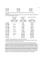
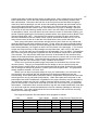
At this point, a word about machining tolerances is in order. When a machinist checks
the specifications of a part that he is about to work with, he always makes note of the
"Tolerances" to which it is to be machined. The term "Tolerance" refers to the amount of
variation in a dimension that is allowed. For example, the specified bore diameter of the
Original Equipment engine is 3.1600", with a tolerance of +.0005" oversize or -.0005"
undersize. This means that a bore diameter anywhere between 3.1595" and 3.1605" is
acceptable. The Original Equipment specified clearance gap between the cylinder bore and
the piston skirt is .0021" to .0033" at the top of the stroke and .0006" to .0012" at the bottom
of the stroke (Yes, the cylinder is actually supposed to be tapered in this manner! The
purpose of the taper is to allow for the greater expansion of the top of the bore due to both it
and the piston crown being exposed directly to the heat of combustion). In practice, this
implies that a 3.1589" skirt diameter piston in a 3.1595" diameter bore or a 3.1599" skirt
diameter piston in a 3.6005" diameter cylinder bore would be technically acceptable.
However, either would be far from ideal as in either case friction would be greater than the
engineering ideal. In an Original Equipment specification engine the engineering ideal would
be to have a skirt diameter clearance of .0027" at the top of the stroke and a .0009" skirt
diameter clearance at the bottom of the stroke, thus minimizing friction at operating
temperatures. The average general-purpose engine machine shop has equipment that can
hold a tolerance of .001" and a good engine machine shop can hold a tolerance of .0005",
while a really good engine machine shop can hold a tolerance of .0001". Obviously, the
tighter the tolerances to which the engine components can be held to the theoretical
engineering ideal, the more powerful and longer-lived the engine can be. However, an
engine machine shop that can hold a .0001" tolerance is never a cheap shop to hire
because of the higher cost of both its equipment and its connected maintenance, not to
mention the superior skill level of those entrusted to work with such high-precision
equipment. In engineering, as with all other things in life, you get what you pay for. In terms
of power output, how significant can trying to hold as close to the engineering ideal be? The
original prototype MGB engines were made under toolroom conditions by the best
machinists that British Motor Corporation had. In finalized form, these precision-made
engines produced 98 HP, and when the original MGB advertisements were released, this is
the power output that was claimed. However, in mass production such strict adherence to
the engineering ideal was not possible. Due to tolerance stacking, some engines produced
as little as 93 HP, while the overall average was in the neighborhood of 95 HP. The
advertisements and publicly released performance specification figures were quickly
changed accordingly. Since the difference between a B Series engine produced to the
engineering ideal and an ordinary, mass-produced one can be as much as 5 HP, as well as
its contribution to an increased lifespan, it is easy to see why the extra investment in the
higher cost of such precise machinework can thought to be worthwhile.
While today’
s sealants are excellent and today’
s modern gaskets possess greater
compressibility than those of the past, they can compensate for warped mating surfaces
only to a very limited degree. Use a Payen or Fel-Pro cylinder head gasket or one that is
marked FRONT/TOP, as these should be quality gaskets. These gaskets are resinimpregnated, have copper sealing rings to better resist excessive crush pressures, and
require no additional sealing coatings. The resin softens when it gets hot and makes a
15
better seal. They are particularly appropriate for use on engines that have been converted
to aluminum alloy heads as they handle the differing coefficients of expansion between a
cast iron block and an aluminum alloy cylinder head quite well. Because of these differing
coefficients of expansion, a copper cylinder head gasket should never be used in
conjunction with a cast iron block and an aluminum alloy cylinder head. Racers like copper
cylinder head gaskets for two reasons: First, because they have high crush resistance, thus
permitting the application of higher levels of torque onto the cylinder head stud nuts in order
to deal with higher pressure levels of both compression and combustion. Second, because
they frequently tear down their engines for inspection. This being the case, they do not want
to have to spend time scraping bits of torn fiber gasket from the mating surfaces. Beyond
those two advantages, copper cylinder head gaskets are obsolete. Never allow a cylinder
head gasket to overhang into the bore of the cylinder, as this will lead to a blown gasket
and/or internal damage to the engine. If you have chosen to build an engine that has a bore
diameter greater than that of the standard maximum oversize (.040”), then you will need a
specialized Big Bore cylinder head gasket. You will need to retorque the cylinder head
immediately after the initial running of the engine. Note that a cast iron cylinder head should
be retorqued while the engine is hot, while an aluminum alloy cylinder head should be
retorqued when it is cold.
During the course of an engine rebuild it’
s common to find that the block is warped
along its longitudinal axis, so we’
re always prepared to line-bore the main bearing and
camshaft journal mounts. Warped mating surfaces are the major contributing factor in
leakage and in the development of cracks in the cylinder head casting. This warpage is
normally the result of the repeated expansion and contraction of the block (i.e., thermal
cycling) gradually relieving the stresses remaining from its original casting process.
However, we rarely stop to consider that this warpage should also extend to the mating
surfaces elsewhere on the engine. The necessity of skimming them flat just as one would
the deck of the block and the mating surface of the cylinder head should always be
explored. To check for warpage in your garage, simply clean the mating surfaces and
smear a very thin stain of machinist's bluing or petroleum jelly on them. In a smooth,
perpendicular motion, place a clean plate glass or a mirror on the surface and then gently
pull it away. Hold it up to a light and look for any gaps in the bluing/petroleum jelly outline.
If you find any, you have warpage. This technique will work with any mating surface. Get
the mating surfaces flat and you’
ll have gone a long way towards having an oil-tight engine.
Remember that machine resurfacing of a gasket area doesn't necessarily guarantee
either flatness or the proper surface finish. That's why the flatness and finish should always
be checked before installing a new gasket. When using a resin-impregnated cylinder head
gasket the surface finish for both the mating surface of the cast iron cylinder head and that
of the deck of the cast iron block should be 80 to 100 RA microinches. When using a steelreinforced cylinder head gasket that combines either a fiber composite or expanded graphite
layers, the surface finish should be 60 to 100 RA microinches. If a rubber-faced
multilayered steel cylinder head gasket is used, then the surface finish should be 30 RA
microinches maximum, but there is no minimum. The smoother it is, the better the seal will
be. When the mating surfaces of an aluminum alloy cylinder head, intake manifold, or
exhaust manifold (aluminum alloy as well as cast iron) are resurfaced, the finish should be
50-60 RA microinches. The surface finish should be fairly uniform across the entire face of
the cylinder head and deck of the block, not varying more than 20% from one area to
another. In addition, there should be no more than plus or minus .001" of out-of-flat across
for 3" in any direction. Pay particular attention to the areas between the cylinders on the
block, between the combustion chambers on the cylinder head, and where the cylinder head
16
gasket seats around the cylinders on both surfaces, as these are the most highly stressed
sealing areas. Any surface flaws that are found should be eliminated by resurfacing.
As a rule, the smoother the surface finish is, the better it is. When the surface is
rougher than about 100 RA microinches, there are too many peaks and valleys on the
metal's surface to achieve a proper seal. The gasket may not cold seal and could leak
coolant, oil, and/or combustion gases. Using a thicker gasket that has increased
conformability and/or a thicker soft facing can compensate somewhat for a rougher surface,
but such gaskets don't retain torque well and are less durable. Too rough a surface finish
has more "bite", digging into the gasket more aggressively, increasing the scuffing and
shearing that the gasket undergoes as the engine expands and contracts. In bimetal
engines that pair cast iron blocks and aluminum alloy cylinder heads, this can be especially
hard on the gasket because of the difference in expansion/contraction coefficients between
aluminum alloy and iron. Too smooth a finish may not provide enough bite to seal the
cylinder head gasket securely. There can also be movement between the gasket and metal,
causing the gasket to abrade and leak.
The most desirable engine blocks for a high output engine are the early 18V blocks of
the 1972 through 1974 Chrome Bumper models. These later blocks have grade 8 bolts
instead of studs for securing their thicker, stronger crankshaft main bearing caps, most
notably the rear crankshaft main bearing cap (MG Part# 12H 1951) in which the oil drainage
slot was eliminated. These can be readily identified by their engine numbers: 18V-581-F-H,
18V-581-Y-H/L, 18V-582-F-H, 18V-582-Y-H/L, 18V-583-F-H, 18V-583-Y-H, 18V-584-Z-L
and 18V-585-Z-L from the 1972 model year, and 18V672-Z-L and 18V-673-Z-L from the
1973 through 1974 model years. It should be noted that the torque reading on a bolt partly
reflects the twist of its shank, while the torque reading on a stud reflects the pulling force
exerted on the stud. Pull is what seats things, so the more accurate reading obtained with a
stud is the better way to go. British Leyland switched from the original BMC stud design to
bolts during a time of cost cutting. These later crankshaft main bearing caps have shallow
recesses for the heads of their mounting bolts while the earlier caps have deeper recesses
for their washers and nuts. The later crankshaft main bearing caps can be used in the
earlier engines only if their appropriate mounting bolts are also used and only if they are
line-bored in place. However, if these bolts are unavailable, ARP makes a set of high
strength studs that may be used as an upgrade (Moss Motors Part# 322-878, APT Part#
MS5B54).
The crankshaft main bearing caps should always be carefully inspected beforehand for
any signs of cracking and their edges smoothed to preclude cracks from forming under the
stress of continual high engine speeds. Advise your machinist that both the crankshaft main
bearing caps and the connecting rods and their end caps are individually matched paired
sets and hence are not interchangeable. When line boring both the main bearing mounts
and the bores for the camshaft bearings, tolerances should be held to +/-.0005". However, it
is well proven that precision machining is beneficial to lengthening the lifespan of a high
performance engine, so after line-boring, these bores should then be line-honed to a
tolerance of +.0001”/ -.0000". This will enable the fitting of the main bearings with just the
right amount of "crush" when being torqued to their specified 70 Ft-lbs and minimize
distortion to ensure concentric running, as well as press-fitting of the camshaft bearings
without the need for any subsequent modification to their Internal Diameters. It should be
noted that both front and rear crankshaft main bearing caps must always be installed flush
against the block.
Following this, the crankshaft should be indexed and the lengths of its throws matched.
This latter operation is essential not only to equalize the swept volume of each cylinder, but
17
also to permit the balancing to match the differing dynamic effects from one cylinder to
another, making for a smoother engine.
When cleaning out the passages inside the crankshaft, be sure to remove all of the oil
flow restrictors. These were installed into the crankshaft in order to prevent centrifugal force
from causing excessive oil flow outward from the crankshaft.
Be aware that the later 18V blocks from the 1975 through 1980 Rubber Bumper models
have a repositioned motor mount boss on the camshaft side of the front engine plate and so
will not fit into earlier cars. These can be readily identified by their engine numbers: 18V836-Z-L, 18V-837-AE-L, 18V797-AE-L, 18V-798-AE-L, 18V-801-AE-L, 18V-802-AE-L, 18V883-AE-L, 18V-884-AE-L, 18V-890-AE-L, 18V-891-AE-L, 18V-892-AE-L, and 18V-893-AEL.
It is not commonly known that the five-main-bearing B Series engines used in the MGB
actually made use of a succession of three crankshafts. The first was a forged EN 16
carbon steel design. It may be found in 18GD, 18GF, 18GG, 18GG, 18GH, 18GJ, and
18GK engines. The second was a cast iron design. Easily recognized by its flared
counterweights, it may be found in 18V-581-F-H, 18V-581-Y-H/L, 18V-582-F-H, 18V-582-YH/L, 18V-583-F-H, 18V-583-Y-H, 18V-584-Z-L, 18V-585-Z-L, 18V-672-Z-L, and 18V-673-Z-L
engines. The third was a forged EN 16 carbon steel design. It may be found in 18V779-FH, 18V-780-F-H, 18V797-AE-L, 18V-798-AE-L, 18V-801-AE-L, 18V-802-AE-L, 18V-836-Z-L,
18V-837-AE-L, 18V846-F-H, L, 18V847-F-H, 18V-883-AE-L, 18V-884-AE-L, 18V-890-AE-L,
18V-891-AE-L, 18V-892-AE-L, and 18V-893-AE-L engines.
The crankshaft with the best balance and wear characteristics is the flat-sided fivemain-bearing cast iron version with flared counterweights found in the early versions of the
18V engines (18V-584-Z-L, 18V-585-Z-L, 18V-672-Z-L, and 18V-673-Z-L). Although
technically slightly weaker than the alternate forged EN 16 carbon steel crankshafts used in
other versions of the five-main-bearing engine and seven pounds heavier than the earlier
three-main-bearing steel crankshafts (32 lbs Vs 25 lbs), it is strong enough for the streetable
enhanced-performance engine that is the goal of this article. Do not succumb to the
temptation to use the less expensive crankshaft from a Morris Marina. It is made of flowcast spheroidal graphite iron and was intended for use in sedate family cars. It is simply not
strong enough for use in an enhanced-performance engine. In addition, it uses a smaller
diameter pilot bushing and a completely different, much heavier (28 lbs) flywheel.
Although the five-main-bearing crankshafts found in MGB engines are all but
unbreakable in an engine rebuilt to Original Equipment specifications, with a seriously
power-enhanced engine that is equipped with a hot camshaft, it is prudent to take
precautions. Be sure to tell the machinist that you want the journals fillet-radiused to .030"
at the web and that they should be glass beaded afterwards in order to both increase the
fatigue life of the crankshaft and to reduce the chances of breakage under heavy loadings at
high engine speeds. Glass beading the fillet reduces subsurface stress risers that result
from the machining process. Racing crankshaft designs often have a larger fillet radius in
the area where the connecting rod journal meets the counterweight. This rounded inside
corner increases crankshaft strength, but can interfere with the big end bearing of the
connecting rod. Many high performance connecting rod big end bearings are chamfered to
provide the side clearance necessary for such filleted crankshaft journals. The chamfers are
used on the sides of the bearing alongside the crankshaft counterweight in order to provide
as much surface area as possible and to provide added protection against side thrust
forces. Even though these bearings are designed for this purpose, it is still important to
check for adequate clearance in their chamfer area. The crankshaft thrust washers
(Federal-Mogul Part# 65077BF) must be installed with their white metal facings and their oil
18
grooves facing away from their adjacent crankshaft journal main bearings, otherwise rapid
wear and possible failure of the crankshaft will result.
Although choosing the dimension that the journals should be reground to may seem to
be a straightforward matter, in reality the purpose to which the engine is intended to be put
to must be taken into account when making the choice. While an engine built to essentially
Original Equipment specification can have its journals ground to the middle of the tolerances
set by the bearing manufacturer, an enhanced performance engine is quite another matter.
As a rule, most outright bearing failures are caused by a localized buildup of heat within the
space between the bearing and the journal. This most commonly occurs at high engine
speeds when the engine is called upon to work against heavy loads, an operating condition
that an enhanced performance engine faces often. This localized buildup of heat causes
the oil to break down and lose its lubricating properties, resulting in bearing failure and
crankshaft damage. This can be countered to a limited degree by increasing the bearing
clearances, which in turn means that the load supporting capacity of the bearing is reduced.
As a compromise, the journal should be sized .0003”to .0005”smaller than the bearing
manufacturer's recommended maximum clearance. This will have an additional benefit of
also reducing oil drag, the result of which will be a very small increase in power output. The
minimum diameter for the crankshaft journals is limited to 2.086".
When reground, the journal surfaces of a crankshaft will have microscopic peaks that
are "tipped" in the direction that the sparks spray during grinding. If allowed to remain,
lubrication will be interrupted when the engine is running and the bearings will wear
prematurely. After the crankshaft has been ground, it is important that all bearing journals
receive a three-step final polishing so that these peaks are tipped into the opposite direction
than that in which the crankshaft rotates. This is referred to as the "favorable" direction. In
the first step 280 grit paper should be used, followed by 320 grit paper, and finished with a
very fine (400 grit) paper for the third and final step.
Be sure to check both ends of the crankshaft for any grooves worn into it by the old
seals. If your machinist cannot polish them out, then it will be necessary to fit a sleeve.
Chicago Rawhide produces a Speedi-Sleeve for the rear end of the crankshaft (Moss
Motors Part# 520-515), while National makes a Redi Sleeve for the front end (National Part#
99156). Moss Motors has a website that can be found at http://www.mossmotors.com/ and
National can be found at the website of its parent corporation, Federal Mogul, at
http://www.federal-mogul.com/.
It should be noted that while there are two different lengths of sintered bronze pilot
bushings (1.000”and 1.500”) used in the spigot end of the five-main-bearing crankshafts,
the crankshaft spigot bore is of the same diameter and depth on all crankshafts, regardless
of whether they are fitted with the long or the short pilot bushing. The shortening of the
bushing was yet another example of cost-cutting by the factory. The longer of the two pilot
bushings provides a greater load bearing surface area and thus wears more slowly,
providing better long-term support for the input shaft of the transmission. Soak the new pilot
bushing in oil for a few days before you install it. The sintered bronze will soak up oil until
saturated, ensuring good initial lubrication.
The front and rear crankshaft main bearing caps are a precision fit in order to enhance
oil retention. They both should be painted prior to installation but no paint should be on their
mating surfaces or in their seal grooves. Under no circumstances should any of their mating
surfaces be cleaned with an abrasive, otherwise leakage will result.
When installing the main bearing plates into the block, do not attempt to expand the
block by heating it with a blowtorch, as this uneven heating will place stress on the block
that can lead to cracking. Do not yield to the temptation to simply place a block of wood
against it and use a heavy hammer to force it into position as this can result in damage to its
19
machined surfaces. Instead, shrink-fit it into place. This will make for ease of proper
alignment without any of the aforementioned risks. I prefer to shrink-fit both the front and
rear crankshaft main bearing caps in order to ease the assembly process, but this is not
really required. Simply place the crankshaft main bearing cap into its respective slot at the
end of the block and use a soft mallet to gently tap it downward into place. As it reaches the
bottom of its slot, tap it into its correct position with its outer face flush with the block.
Using a pair of long 1/2"-20 UNF bolts to align the crankshaft main bearing cap, turn
each retaining bolt about one-half turn at a time until the crankshaft main bearing caps are
almost seated. As they descend, change to shorter bolts. When they are almost fully
seated, use the factory bolts, again a half-turn at a time, to fully seat them.
Installation of the cork seals for the front and rear crankshaft main bearing caps is often
problematic for some owners. This is often due to the fact that although only two are
required, rebuild kits are frequently supplied with several different cork seals of differing
cross-sections and lengths. This is due to the fact that that prior to the introduction of the
18V engines, the square cross-section seal went onto the rear crankshaft main bearing cap
and the rectangular cross-section seal onto the front crankshaft main bearing cap. When
the 18V engines were introduced, they were standardized on two square cross-section
seals. One of the reasons that cork was chosen for use as a seal was its compressibility.
Because this quality can vary, the seals are supplied in overlengths so that the mechanic
can fine-tune its length.
Getting the cork seals to the right length requires some patience. The groove of the
flange into which they fit must be clean and unpainted, otherwise the gaskets will eventually
seep oil. Insert the ends of the cork seal into the groove of the flange so that its middle
bows upwards, then gently press its ends outwards towards the ends of the grooves. If the
seal still bows upwards in the middle when light pressure is exerted upon it, do not attempt
to force it down. Instead, remove it and use a single edge razor blade to cut 1/32" of material
from one end. This should be done with care being taken to assure that the cut is
perpendicular to the longitudinal axis of the seal; otherwise, there will be a likelihood of
leakage from the poorly cut end. Repeat this process until the seal just compresses into its
slot. When this sizing is accomplished, remove the seal and then use some Permatex
Aviation Form-A-Gasket or Hi-Tack to secure it into position. The finished seals must
extend slightly above the flange so that they will be compressed when the sump is bolted
down.
The secret to measuring crankshaft endplay lies in remembering that steel is actually
more elastic than rubber. If you drop a rubber ball and a steel ball bearing of identical
diameters from an identical height, then the steel ball bearing will bounce higher every time!
Consequently, it is always best to push the crankshaft as far as it will go rather than to tap it
and risk it bouncing backward or forward. Remember, we're dealing in thousandths of an
inch here! If you push (or lever) it as far as it will go, your measurements will be more
accurate. These measurements should also be done dry, i.e., without oil, and with the
center crankshaft main bearing cap loose on its bolts/studs, so that the crankshaft lines up
the two sets of thrust washers. Only then should you tighten down the center crankshaft
main bearing cap and check endfloat with a dial gauge on the nose of the crankshaft. While
too little play is worse than too much, it should be noted that whenever endthrust is applied
to the crankshaft (such as when applying the clutch), the lateral acceleration of the
crankshaft increases with its lateral movement. Thus, the greater the endplay, the greater
the impact loading against both the thrust washers and bearings and, as a consequence,
the greater and more rapid the wear. The endplay should always be the same (.004" to
.005") whenever the crankshaft is moved as far as it will go (this is what machinists call
"repeatability").
20
There are two factors involved in balancing an engine, respectively referred to as
Primary and Secondary Factors. The term Primary Factor refers to vibration that is induced
by reciprocating components (Primary vibration), such as piston assemblies and connecting
rods. The term Secondary Factor refers to vibration that is induced by rotating components,
such as the crankshaft and the flywheel (Secondary vibration).
The effective length of the connecting rods (eye center-to-eye center distance) should
be matched in order to establish a uniform connecting rod to stroke ratio. If possible, have
the connecting rods balanced end-for-end. This means that the Small Ends of the
connecting rods should all be matched for weight and their Big Ends should also all be
matched for weight. The total weight of each connecting rod should then be matched to the
others. In doing so, the equalized oscillating dynamic forces produced by their reciprocal
movement in cylinders #1 & #4 will be equal to those produced in cylinders #2 & #3,
effectively canceling each other out and thus reducing primary vibration. In addition,
because of the equalized weights, the centrifugal forces created by the connecting rods
upon the opposing throws of the crankshaft will be equalized, thus reducing secondary
vibration. This will aid in maintaining concentricity of the axis of the crankshaft with that of
the bearing bores, not only reducing both bearing and journal wear, but also reducing
pressurized stress on their lubricant.
Although the prospect of balancing your own connecting rods may seem to be an
intimidating task, it is actually a rather simple and straightforward operation to perform. If
you work patiently, you can match the respective weights to within .1 gram, which is as good
as or better than any professional shop can accomplish. You will need a scientific scale with
excellent "repeatability". The term "repeatability" means that every time that the same
object is placed upon it; the scale should always give the same weight readout. Actual
calibrated accuracy is unnecessary. Since we are dealing only with relative differences in
weight, it is only necessary that the scale have excellent repeatability.
The big end of each assembled connecting rod is placed on a ball that acts as a fulcrum
point and its small end placed on the middle of a scientific scale. Once the lightest big end
of the connecting rods is identified, the adjacent balance pads on the heavier ones are
lightly ground on a fine stone until the weight of their big ends are equal to that of the lightest
one of the set. Should the connecting rods be of the type that has no balance pads, the
metal must be carefully removed from the entire length of the curvatures on the opposing
ends. All grinding must be perpendicular to the pivot axis of the connecting rod, never
parallel to it. Care must be taken to not overheat the metal in order to avoid annealing the
metal. Should the metal turn blue, it is annealed and thus useless. Scrap it.
Next, the small end of each assembled connecting rod is placed upon a ball and its big
end placed on the middle of the scientific scale. Once the lightest small end of the
connecting rods is identified, the adjacent balance pads on the heavier ones are also lightly
ground on a fine stone until the weight of their small ends are equal to that of the lightest
one of the set.
Once the grinding process is complete, all grinding marks should be removed by
polishing in order to prevent the formation of stress risers, which can develop into cracks.
This operation can be easily performed with a Dremel tool fitted with a polishing bit. After
polishing, the ends of the connecting rods should be reweighed and any discrepancies in
weight resolved by polishing. Once the balancing process is finished, all of the components
should be disassembled and thoroughly cleaned.
Pistons that use only three rings are lighter than the older-design four-ring and obsolete
five-ring designs. Both the piston/ring/wrist (gudgeon) pin assemblies and the connecting
rod assemblies should be matched respectively to within .10 of a gram.
21
Matching the weight of the piston assemblies is a more involved and time-consuming
process than that of balancing the connecting rods. Each bare piston, wrist (gudgeon) pin,
and ring must be weighed and their individual weights recorded. The components are then
assigned to a piston according to their weight, i.e., the lightest components are assigned to
the heaviest piston, and the heaviest components are assigned to the lightest piston. The
total weight of each assembly is then recorded. This approach allows the variation of the
total weights of the assemblies to be minimized, simplifying the weight removal process by
minimizing the amount of material to be removed.
Material is then lightly removed from around the wrist (gudgeon) pin bosses inside the
pistons as well as from the inside of the skirts of the bare pistons until the total weight of the
heavier piston assemblies are equal to that of the lightest one. In order to avoid weakening
the pistons, material removal should be distributed evenly across as wide an area as
possible. This operation is best performed with a Dremel tool fitted with a polishing bit.
After polishing, the pistons should be reweighed and any discrepancies in weight resolved
by polishing. Once the matching process is finished, all of the pistons should be thoroughly
cleaned and assembled in order to prevent mismatching of the components.
The reciprocating masses having thus been matched, the crankshaft, harmonic
balancer pulley, and the flywheel should then be dynamically balanced separately and
subsequently checked for balance as a complete assembly. The flywheel should be
balanced only after its clutch friction surface has been skimmed smooth and its balance
factor determined with both the ring gear and the clutch cover attached. A balance factor
near 1.0 indicates an engine whose primary vibration is in line with piston motion (the engine
vibrates up-down), while a value near 0.5 results in an engine that vibrates more in a circle.
If you are using the flared counterweight iron crankshaft of the early versions of the 18V
engine, balancing will need to accomplished by drilling or by both grinding and polishing in
order to remove material. However, if you are using the flat-sided steel crankshaft and you
can afford it, advise the machinist that you would prefer that the dynamic balance of the
crankshaft be achieved by wedging rather than by drilling. While the involved machinework
is much more expensive than drilling, wedging will reduce both stress risers and oil drag, as
well as greatly assisting in prolonging main journal bearing life. In addition, the reduction in
rotational mass produced by wedging will produce the same positive effect on rapid changes
of engine speed as that which reducing the weight of the flywheel can achieve, although
without incurring the attendant liability of increased secondary vibration. By achieving a
reduction of rotational mass in this manner the flywheel can retain the same mass, thus
retaining its ability to absorb heat without warping, as well as providing sufficient inertia to
smooth the power impulses of the engine. It is not only unnecessary to knife-edge the
corners of the crankshaft counterweights of a street engine in an attempt to reduce windage
loss, it is actually undesirable. Knife-edging can result in stress points that can lead to
fracturing. Instead, a generous radius on each corner of the crankshaft will reduce both oil
and air drag to approximately 90% of that attained by knife-edging. These procedures are
fundamental to producing the smoothest running engine possible and will provide a bit more
power that would otherwise be lost to the production of vibration, in some engines perhaps
as much as 2 HP. It will also result in reduced main bearing wear due to more concentric
running. Due to their relatively superior machining characteristics, the alloy of the flat-sided
five-main-bearing cast iron version of the crankshaft found in the early 18V engines (18V584-Z-L, 18V-585-Z-L, 18V-672-Z-L, and 18V-673-Z-L) is the easiest for a machinist to work
with.
The obliquely-split connecting rods (BMC Part # 12H998 for cylinders #1 and #3, BMC
Part # 12H997 for cylinders #2 and #4) first used in the three main bearing 18G and 18GA
engines used a smaller-diameter (.750") wrist (gudgeon) pin secured by a pinch-bolt small
22
end, thus making them noninterchangable into later engines without using their wrist
(gudgeon) pins as well as their accompanying obsolete four-ring pistons. Both they and the
obliquely-split connecting rod (BMC Part # 12H1019) of the five main bearing engine (18GB,
18GD, 18GF, and through early 18GH Series) weighed in at a ponderous 980 grams. Not
only are they heavy, they are notoriously weak for use in highly stressed engines. The
horizontally-split connecting rods with balance pads (BMC Part # 12H3596) used in the late
18GH, 18GJ, 18GK, and through early 18V engines were a notably lighter 845 grams.
There were two variants of this connecting rod. The first variant is found in the 18GH, 18J,
and 18K engines and has a bushed small end for use with a floating wrist (gudgeon) pin that
is secured within the piston by circlips. The later variant that is found in the early 18V
engines has an unbushed small end for use with a press-fitted wrist (gudgeon) pin. The
final connecting rod design used in the late 18V engines had no balance pads (BMC Part#
CAM1588) and were the lightest, weighing 760 grams, slightly in excess of 1/3 more than
the Arrow Precision connecting rod. The most desirable connecting rods for any engine are
the lightest ones as, due to their reduced inertia, their reciprocation will not only produce
less primary vibration and power loss, but also less stress is placed upon their big end
bearings as well. These can commonly be found on engines whose identification numbers
start with 18V-883-AE-L, 18V-884-AE-L, 18V-890-AE-L, 18V-891-AE-L, 18V-892-AE-L, or
18V-893-AE-L.
Be aware that the connecting rods used on the 18GB, 18GD, 18GF, 18GG, 18GH,
18GJ, and through early 18GK engines use the larger 13/16" (.8125") wrist (gudgeon) pins
that floated in a press-fitted bushing in the small end of the connecting rod. This bushing
was later eliminated in those of the late 18GK through 18V engines. These later connecting
rods also used the larger 13/16" diameter wrist (gudgeon) pins, but in their case, they were
press-fitted into the connecting rods, so your pistons must be chosen accordingly. However,
the small end of the later connecting rods can be machined to accept the earlier bushing if
floating pistons are desired. In the cases of both types, an assembly lubricant must be
applied to prevent galling during initial fire-up of the engine. Due to the fewer parts involved
with a press-fitted wrist (gudgeon) pin/piston assembly, more precise control is attainable
than with a floating assembly. However, wear of the wrist (gudgeon) pin bores of the piston
is greatly accelerated. Actual stresses, depending on cylinder gas pressures and engine
speeds, are influenced by wrist (gudgeon) pin ovalization and bending, as well as by the
hydrodynamic oil film pressure distribution in the pin bore. A floating wrist (gudgeon) pin
configuration allows the wrist (gudgeon) pin to rotate during engine operation. As compared
to a fixed wrist (gudgeon) pin, this prevents the wrist (gudgeon) pin from repeatedly flexing
into a fatigue-inducing bow shape. Reduced wrist (gudgeon) pin clearances always have a
positive effect. Wrist (gudgeon) pin to pin bore installation clearances can be reduced
approximately 50 percent and configurations can thus be designed for higher specific pin
bore surface pressures at peak cylinder gas pressure. Once the lower limits are established
(example: scuff issues), upper installation clearances can be minimized.
Electropolishing and shot peening of the connecting rods are necessary only if you're
going racing. However, smoothing of all of the edges on a connecting rod can greatly aid in
decreasing the possibility of pressure risers from forming fissures that will develop into
fractures. Note that exotic lightweight connecting rods such as those marketed by Carrillo
(588 grams) and Arrow Precision (570 grams) are primarily intended for racing use and are
unnecessary for use in all but the most radical of street engines, although their lower
reciprocating mass will reduce both horsepower loss and the amplitude of vibration caused
by primary imbalance, although not its frequency. They also both make use of cap bolts to
secure their main bearing caps instead of through-bolts or studs, thus endowing them with
23
the rigidity that is necessary for reliability at unusually high sustained engine speeds. It
should be noted that both of these designs use floating wrist (gudgeon) pins.
Although pistons may seem to be simple to the naked eye, they are actually of quite
sophisticated design. Piston skirts are designed so that they give optimum profiles at full
running temperature. They are not round. Instead, they are elliptical and their vertical profile
is not straight. In areas where the piston runs hotter, expansion is greater and thus
allowances for this have to be made to accommodate this in the skirt profile. This profile,
both radial and vertical, is extremely critical and a diametrical adjustment of only five
microns (0.0002") can make all the difference in achieving optimum results. The profile
turning lathes that produce this ovality and vertical profile on the piston skirt easily produce
repeatability within +/- .0002".
For most applications hypereutectic pistons will perform quite well. These are cast
pistons made from an aluminum alloy that has over a 16% silicone content for strength and
durability. Special melting processes are necessary in order to supersaturate the aluminum
with additional silicon content. Special molds, as well as special casting and special cooling
techniques are required in order to produce finely and uniformly disperse the silicon particles
throughout the material. This produces pistons that are very hard, but rather brittle. This
being the case, they are longwearing, yet have proven to be unforgiving of detonation. Their
reduced coefficient of thermal expansion allows the piston to be run with reduced
clearances, which reduces scuffing as well as losses due to gases escaping past the sealing
rings.
The compression ring at the top of the floating four-ring floating piston receives less
lubrication than in the later three-ring floating and press-fit designs, so both the compression
rings and the bores wear faster. However, with modern lubricants this difference is
minimized, though still present. The biggest objection to the earlier four-ring pistons is that,
being 3" long, their weight is greater than that of the later 2.4" long three-ring design. It
takes more power to make that extra weight reciprocate up and down inside the engine, and
the amplitude of primary vibration produced is increased. Due to the improved load-bearing
capacities of modern engine lubricating oils, the reduced load-bearing surface area of the
shorter three-ring pistons does not present a wear problem for either the piston or the
cylinder wall. These are the reasons why the factory chose to redesign the assembly in this
manner.
However, there is an even more important reason why the four-ring piston is
inappropriate for a high performance version of the B Series engine. Because of both the
combustion characteristics of the available fuels during the era in which they were designed
and the vulnerability of the gray iron of which the compression rings were then being
designed, there was a risk of the compression ring being damaged by the heat of
combustion. In time advances in metallurgy resulted in compression rings that were less
susceptible to combustion damage, the most significant of which was the development of
more suitable alloys of Ductile Iron. Ductile Iron's high strength, wear resistance, and
elasticity combine to allow heavier loads with less deflection. Coupled with the advent of
better fuels, the designers were able to relocate the compression ring further down from the
crown of the piston in the design of the more modern three-ring pistons in order to further
prevent damage from combustion. Unfortunately, under rich running conditions unburned
fuel can condense above the compression ring and in its groove, waiting there to detonate
should preignition occur. This leads to fracturing of the ring and, in extreme cases,
breakage of the neighboring land. Because of structural weakness stemming from the
drainage slot from the oil ring groove extending to the wrist (gudgeon) pin boss, this in turn
can cause the upper section of the piston to fracture and separate from its skirt.
24
I'd suggest using the more modern three-ring pistons with bushed small end connecting
rods and having the wrist (gudgeon) pin bores of the pistons grooved to accept wrist
(gudgeon) pin retainers so that you can have a floating wrist (gudgeon) pin system. That
way you can have the best of both worlds! If you desire lighter connecting rods to further
reduce primary vibration and its attendant power loss, the late Original Equipment ones
without the balance pads found on the late 18V engines can be modified to accept the
necessary small end bushings and will fit this requirement at minimal cost. These were
installed into all production engines in sets that were reasonably matched for weight at the
factory, so little modification is necessary to bring them into precise balance.
The following table may be used as a guide in choosing your piston size:
Bore Oversize
+.000
+.010"
+.020"
+.030"
+.040"
+.060"
83mm
83.5mm
Displacement
1798cc
1812cc
1822cc
1834cc
1844cc
1868cc
1924cc
1948cc
It should be noted that the factory supplied oversize pistons only up to +.040”oversize
due to variations in the thickness of the cylinder walls and problems with porosity that were
due to the limitations of casting technology of the era. To bore beyond this diameter may
require the use of sleeves (liners).
While many engine designers sought to reduce wear of the bore, rings, and piston by
distributing side thrust forces over as large an area as possible, as in the case of engines
having a large bore coupled with a short stroke, the attendant loss of thermal efficiency
resulting from the accompanying large roof of the combustion chamber was deemed to be
inefficient. Instead, the designers deemed lubrication to be the proper solution. In order to
accomplish this connecting rods with the unusual feature of an oil squirt passage was
devised. Contrary to what some amateur engine builders may believe, positioning the
connecting rods so that the oil squirt passages face the camshaft is not necessary as the
camshaft receives excellent lubrication from both the pressure galleries in which its journals
spin plus residual oil flowing down the pushrod bores from the rocker arm assembles, as
well as oil sprayed from the crankshaft's main bearings and connecting rod big end bearings
at the crankshaft. When installed, the oil squirt passage of each of the connecting rods
must face the side of the engine opposite the camshaft to both cool the piston and better
lubricate the load bearing surfaces during the power stroke. Failure to do this will eventually
result in extreme piston pin wear within the piston itself, plus create the very real likelihood
of piston failure, not to mention increased bore wear as well. Be aware that on some
connecting rod bolts, only one side of the bolt head is chamfered to provide sufficient
clearance for the camshaft, so note this fact when you reassemble them.
If a connecting rod bolt is installed without proper preload (prestretch), then every
revolution of the crankshaft will cause a separation between the body of the connecting rod
and its cap. Under load, this insufficient preload will cause additional stretch in the bolt.
This stretch is removed when the load is removed on the upward stroke of each revolution.
This cycle of stretching and relaxing can cause the connecting rod bolt to fatigue and
fracture. In order for this cyclic stretching to be prevented from occurring, the preload of the
bolt must be greater than the load caused by the cycling of the engine. A properly installed
25
connecting rod bolt remains stretched by its preload and isn't exercised by the by the cyclic
loads imposed on the connecting rod. A quality bolt will stay stretched for years in this
manner without fracturing. When tightening, it is important to prevent the bolt from failing as
a result of the stress induced by tightening it to a load greater than that of the demand
placed upon it by the engine. In other types of bolted joints, this careful attention to detail is
unimportant. For example, flywheel bolts need only be torqued to their specified 40 Ft-lbs in
order to prevent them from working loose. Flywheel loads are carried either by shear pins or
by side loads in the bolts; as such, they don't cause cyclic tension loads in the bolts. On the
other hand, connecting rod bolts support the primary tension loads caused by engine
operation and must be protected from cyclic stretching. That's why proper tightening of the
connecting rod bolts is so important. These same conditions also apply to the fasteners of
the crankshaft main bearing caps.
There are three methods that can be employed to determine how much tension should
be exerted on a fastener: using a torque wrench, measuring the amount of stretch and
turning the fastener a predetermined amount (torque angle). Of these methods, the use of a
stretch gauge is the most accurate. It is important to note that in order for a fastener to
function properly it must be "stretched" a specific amount. The material's ability to "rebound"
like a spring is what actually provides the clamping force. Different materials react
differently to these conditions, and engineers design bolts to operate within specific ranges.
If a fastener is over-torqued and becomes stretched too much, then its yield strength has
been exceeded and it is ruined. If the fastener is longer than manufactured, even if it is only
.001", it is in a partially failed condition. Therefore, fasteners are engineered with the
ductility to stretch a given amount and then rebound to produce the proper clamping force. I
highly recommend the use of a stretch gauge when installing connecting rod bolts wherever
it is possible to measure the fastener as it’
s the most accurate way to determine correct
stretch. The use of the torque wrench data is only for guide purposes.
While the torque figure for the obliquely split connecting rods is 35 to 40 Ft-lbs and 33
Ft-lbs for the horizontally split connecting rods, a torque wrench essentially measures the
amount of torque necessary to overcome friction, not actual clamping force. Friction is an
extremely challenging problem because it is so variable and difficult to control. The best
way to avoid the pitfalls of friction is by using the stretch method. This way preload is
controlled and independent of friction. Each time the bolt is torqued and loosened, the
friction factor gets smaller. Eventually the friction levels out and becomes constant for all
following repetitions. Therefore, when installing a new bolt where the stretch method cannot
be used, the bolt should be loosened and tightened several times before final torque. The
number of times depends on the lubricant. For ARP recommended lubricants, five loosening
and tightening cycles are sufficient.
Ensure that the mating faces are wiped clean and use solvent to remove any old grease
from threads of the bolts and the mating surfaces of the connecting rod assembly. Apply
ARP moly assembly lubricant to both the seating face of bolt and the threads of both the bolt
and the connecting rod. Next, assemble the cap to the connecting rod and torque the bolt to
15-20 Ft-lbs, then tighten each bolt to recommended stretch value, i.e., loosen the first bolt,
zero the stretch gauge, and tighten until correct stretch is achieved. Finally, loosen the
second bolt and repeat the process until both of the connecting rod bolts have the correct
stretch. To optimize the accuracy of the big end bore size and roundness, and to achieve
correct bolt preload, each bolt should be stretch gauged. Remember: a torque wrench
setting should be considered to be a guide only.
However, if you don't have access to a stretch gauge, the following torque values
should be of use to you as different grade fasteners require different torque values-
26
1/4"-20tpi
1/4"-28tpi
5/16"-18tpi
5/16"-24tpi
3/8"-16tpi
3/8"- 24tpi
7/16"-14tpi
7/16"-20tpi
1/2"-13tpi
1/2"-20tpi
9/16"-12tpi
9/16"-18tpi
5/8"-11tpi
5/8"-18tpi
3/4"-10tpi
3/4"-16tpi
7/8"-9tpi
7/8"-14tpi
Unlubricated* or
Unplated Threads**
Regular Hex
Grade 5 Bolt
Grade 5 Nut or B Nut
Torque: Ft-Lb (Nm)
8 (11)
9 (12)
15 (20)
17 (23)
28 (38)
31 (42)
46 (61)
50 (68)
70 (95)
75 (102)
100 (136)
110 (149)
135 (183)
155 (210)
240 (325)
270 (366)
385 (522)
425 (576)
Unlubricated* or
Unplated Threads**
Regular Hex
Grade 8 or 8.2 Bolt
Grade 8 or C Nut
Torque: Ft-Lb (Nm)
10 (14)
12 (16)
22 (30)
25 (34)
40 (54)
45 (61)
65 (88)
70 (95)
95 (129)
110 (149)
140 (190)
155 (210)
190 (258)
215 (292)
340 (461)
380 (515)
540 (732)
600 (813)
* It is recommended that all plated and unplated threads be coated with oil before
installation.
** Use these torque values if either the bolt or the nut is lubricated or plated (Zinc-Phosphate
coated, Cadmium-plated, or waxed.
1/4"-20tpi
1/4"-28tpi
5/16"-18tpi
5/16"-24tpi
3/8"-16tpi
3/8"- 24tpi
7/16"-14tpi
7/16"-20tpi
1/2"-13tpi
1/2"-20tpi
9/16"-12tpi
9/16"-18tpi
5/8"-11tpi
5/8"-18tpi
Lubricated* or
Plated Threads**
Regular Hex
Grade 5 Bolt
Grade 5 Nut or B Nut
Torque: Ft-Lb (Nm)
7 (9)
8 (11)
15 (20)
16 (22)
26 (35)
30 (41)
42 (57)
47 (64)
64 (87)
72 (98)
92 (125)
103 (140)
128 (173)
145 (197)
Lubricated* or
Plated Threads**
Regular Hex
Grade 8 or 8.2 Bolt
Grade 8 or C Nut
Torque: Ft-Lb (Nm)
8 (11)
9 (12)
16 (22)
17(23)
28 (38)
32 (43)
45 (61)
50 (68)
68 (92)
77 (104)
98 (133)
110 (149)
136 (184)
154 (209)
27
3/4"-10tpi
3/4"-16tpi
7/8"-9tpi
7/8"-14tpi
226 (306)
253 (343)
365 (495)
402 (545)
241 (327)
269 (365)
388 (526)
427 (579)
* It is recommended that all plated and unplated threads be coated with oil before
installation.
** Use these torque values if either the bolt or the nut is lubricated or plated (Zinc-Phosphate
coated, Cadmium-plated, or Waxed.
1/4"-20tpi
1/4"-28tpi
5/16"-18tpi
5/16"-24tpi
3/8"-16tpi
3/8"- 24tpi
7/16"-14tpi
7/16"-20tpi
1/2"-13tpi
1/2"-20tpi
9/16"-12tpi
9/16"-18tpi
5/8"-11tpi
5/8"-18tpi
3/4"-10tpi
3/4"-16tpi
7/8"-9tpi
7/8"-14tpi
Unlubricated,
Unplated
Flanged
Grade 8 or Grade G
8.2 Bolt
Nut
Torque: Ft-Lb (Nm)
__
__
22 (30)
__
40 (54)
__
65 (88)
__
95 (129)
__
140 (190)
__
190 (258)
__
340 (461)
__
__
__
Lubricated* or
Plated**
Flanged
Grade 5 Grade 5
Bolt
or B Nut
Torque: Ft-Lb (Nm)
6 (8)
7 (9)
13 (18)
14 (19)
23 (31)
25 (34)
35 (47)
40 (54)
55 (75)
65 (88)
80 (108)
90 (122)
110 (149)
130 (176)
200 (271)
220 (298)
320 (434)
350 (475)
Lubricated* or Plated**
Flanged
Grade 8 or Grade G
8.2 Bolt
Nut
Torque: Ft-Lb (Nm)
10 (14)
12 (16)
21 (28)
23 (31)
37 (50)
42 (57)
60 (81)
66 (89)
91 (123)
102 (138)
130 (176)
146 (198)
180 (244)
204 (277)
320 (434)
357 (484)
515 (698)
568 (770)
* Threads may have residual oil, but will be dry to the touch.
** Both male and female threads (bolt and nut) must be unlubricated and unplated; if either
is plated or lubricated, use the first two tables above.
Be sure that both the mating surface of the cylinder head and the deck of the block
have been skimmed flat and that all of the stud mounting holes and coolant passages are
chamfered, or at best you'll ultimately experience a blown cylinder head gasket or at worst a
cracked cylinder head. Flycutting lacks precision and should be used only as a cost-cutting
measure for removing metal prior to the final precision cut. An end mill produces a superior
finish for street machines because the grooves left behind by the end mill provides a surface
that the cylinder head gaskets can bite into and thus produce a better seal. After milling, the
ridges at the edges of the grooves left on surface of the deck of the block by the machining
process should be removed and both the edges of the combustion chamber, cylinder bores,
and the valve seat counterbores must be carefully deburred and smoothed to preclude the
possibility of "hot spots" developing and thus prevent preignition from consequently
28
occurring. A surface ground finish is acceptable only for racing engines that use only
copper cylinder head gaskets and face frequent disassembly. Note that the deck of the
block must be parallel to the axis of the crankshaft. The Original Equipment specification
piston crown to deck depth dimension is .040". When calculating piston crown to deck
depth dimension, always allow .002"-.003" for connecting rod stretch that is produced by
inertial forces at high engine speeds.
Establishing piston crown to deck clearance is a relatively straightforward procedure.
After oiling the crankshaft main bearings and crankshaft journals to protect them from
scuffing, install them and torque the crankshaft main bearing caps to their standard
recommended values. Next, after oiling the bores, install each of the connecting rod and
piston assemblies using one old compression ring in order to stabilize and center each of
the pistons in their bores. Be sure that they are properly vertically aligned. Using a dial
indicator mounted on a magnetic stand affixed to the deck of the block, rotate the crankshaft
back and forth until the front piston is indicated as being at Top Dead Center. At this point a
depth micrometer or the extending end of a vernier caliper can be used to establish piston
height by measuring directly above the axis of the wrist (gudgeon) pin in order to establish
the piston crown to deck clearance. This is also the perfect opportunity to check the
accuracy of the Top Dead Center timing mark on the crankshaft damper. If the mark does
not properly align, use an offset key to get it right.
Aside from matching the weights of the reciprocating components and independent
dynamic balancing of both the crankshaft and the flywheel, perhaps one of the best ways to
create a smooth engine is to equalize the compression and thus the power impulses
occurring in each cylinder. Once the crankshaft and the connecting rods have been
indexed, this can be accomplished by making sure that the combustion chambers are of
equal volume so that the compression ratio in each cylinder will be the same. The volume
of each combustion chamber can be measured after the cylinder head has been skimmed
flat by using a clear piece of sheet plastic with a small hole drilled in it. Simply put a bead of
chilled grease around the edge of a combustion chamber and press the plastic down onto it
so that the grease forms a seal. Using a syringe or an eyedropper with a scale of
measurement on it, carefully fill each combustion chamber with light oil, keeping a record of
how much is necessary to fill each one. Next, use a cylinder head gasket as a template to
outline the desired profile of the combustion chambers. Use a Dremel tool to gently remove
small amounts of metal from the smallest combustion chamber. Work slowly. For smallbore engines (+.040 or smaller), the walls of the combustion chamber should be kept
perpendicular to its roof in order to ensure the best squish characteristics. On small-bore
engines (+.040”or smaller), the roof of the combustion chamber should be flush with the
valve seat and reasonably flat in order to ensure the best air flow characteristics. Finishing
can be done with a sanding disc, care being taken to not undercut or groove the base of the
wall where it adjoins the roof. This juncture should have a generous radius in order to both
permit smooth air flow and to discourage the formation of carbon deposits that can lead to
preignition. Remove no more material than is absolutely necessary to achieve your goal as
the roof of the combustion chamber is very thin, having cooling passages above. Do not
polish either the walls or the roof of the combustion chamber in an attempt to discourage
carbon buildup as this will lead to condensation of the fuel/air charge both as it enters the
cylinder and as it is being compressed. A glass-beaded finish will produce sufficient border
turbulence to do nicely in terms of discouraging not only this problem, but that of the
development of surface cracks as well.
Unshrouding the valves of the B Series engine is a tricky business, bordering on being
a black art. Theoretically, the adjacent combustion chamber wall should be about 50% of
the radius of the intake valve distant from the edge of the intake valve and 40% of the radius
29
of the exhaust valve distant from the edge of the exhaust valve. However, due to the close
proximity of the combustion chambers to one another and the undersquare configuration of
the cylinders, this theoretical ideal cannot be attained. As a result, some rather artful
techniques have to be employed to attain the desired air flow.
Depending on the size of the intake valve, bore diameter, camshaft, and intended use
of the engine, sections of the walls of the combustion chamber, particularly in the vicinity of
the intake valve, may require an angle progressively increasing from 7° to 14°. Their
juncture with the roof of the combustion chamber must be properly radiused. Although
effecting squish characteristics, this angled orientation of the walls of the combustion
chamber is advantageous because when the valve is near its seat, the close base of the
wall of the combustion chamber does not cause air flow restriction. Increasing the volume
of the combustion chamber further would both not only decrease the compression ratio, but
also by reducing squish turbulence it would become a contributing factor to preignition. It
would also present a grave risk of accidentally breaking through to a cooling passage. This
angled wall modification having been done, it is only when the valve opens further that the
close proximity of the wall of the combustion chamber interferes with air flow. Care must be
taken that in any attempt to unshroud the intake valve you do not attempt to remove too
much material from the combustion chamber wall nearest to it as this can lead to breaking
into a coolant passage.
Unshrouding is obviously best left to experts who are well familiar with the hazards
involved. Instead, confine your work to within the boundaries of the proscribed adjacent
profile established by the cylinder head gasket and simply remove material evenly from the
roof of the combustion chamber. As you remove material, measure the volume of the
combustion chamber repeatedly until it matches that of the largest one. Repeat this process
on all of the combustion chambers until their volumes all match. You should now have
equal compression on all four cylinders, making for a smoother engine.
Glass beading to relieve stress works on machined surfaces to reduce subsurface
stress risers that result from the machining process, as in the case of the fillets of crankshaft
journals, but will do nothing deep inside a casting which is essentially a bunch of holes held
together by metal. Glass beading a casting essentially simply compacts the surface,
creating a density differential that will prevent subsurface cracks from merging with the
surface. The cracks will still be there inside the casting, but they're less likely to get through
to the surface. This is the reason why so many race engine builders glass bead their
combustion chambers, crankshaft fillets, and connecting rods.
If so, be careful to maintain the original symmetry of the thrusts of the opposing ends of
the rocker arms in order to avoid excessive side thrust loadings of the valve stems against
their guides and the rocker pads against the tip of the stem. A precise technique for
establishing this symmetry is to obtain the needed installed valve stem height measurement
with a depth gauge. It will be easiest to make these measurements by inserting and
removing the valves in their guides one at a time without their valve springs in order to
provide clearance for the depth gauge. This calculation can be accomplished by subtracting
the amount of material removed during skimming from the original height of the head casting
then adding the measured height of the installed valves, and then factoring in the difference
between the installed height of the original valves and that of the new valves. Shims can
then be used in order to create the most effective height location of the rocker shaft. Those
who lack precision measuring instruments can also use a less precise alternate technique.
The rocker arm pads should be laterally central over the valve and centered longitudinally
on the end of the valve when at half lift. This can be easily established by placing
machinist's bluing on the tips of the valve stems and examining their print marks on the
thrust faces of the rocker arms. If necessary, shims can be used to create this symmetry.
30
Should it prove to be necessary to shim the rear rocker shaft pedestal in order to achieve
the desired height, note the position of the oiling hole on the bottom of the rocker shaft
pedestal and modify the shim(s) accordingly so that the rocker arm bushings and rocker
shaft will receive adequate lubrication.
Note that on the rear rocker pedestal there is a small screw (BMC Part# 2A 258)
that is held in place with a retaining plate (BMC Part# 2A 259), maintaining the proper
alignment of the oil feed passage in the rocker pedestal to the one in the rocker shaft.
Movement of the rocker shaft and consequent misalignment will result in oil not flowing
through into the shaft and then onward to the individual rocker arm bushings. The plate
serves the simple purpose of securing the screw against the rocker stud.
When installing the rocker arm studs, be aware that they have different threads on each
end. The top end of the stud is 5/16-24, while the lower end has 5/16-18 threads. Do not
succumb to the temptation to install a set of aluminum rocker pedestals from the smaller
version of the B Series engine used in the MGA. Because of the greater coefficient of
expansion/contraction of aluminum, setting of valve clearances will be a problem. Aluminum
being a soft material, the pedestals tend to either collapse upon being over-torqued or
gradually spread under load, causing inadequate clamping force to be exerted upon the
head gasket. A blown head gasket will be the result. As if that isn't bad enough, distortion
of their bores also distorts the rocker shaft, leading to its eventual breakage. The top of the
pedestal is relatively thin where it passes over the rocker shaft, making it prone to cracking.
If a thin or non-hardened washer used, the top of the aluminum pedestal will be deformed
with a slight depression, which in turn will cause small stress fractures to start in the
aluminum pedestal, the result being that the pedestal is fated to break and allow the rocker
shaft to move upward as the pushrods lift the adjacent rocker arms. This upward bending of
the end of the shaft will dramatically increase the stress on the nearest pedestal, which is
then very likely to fracture as well. Small wonder that they were discontinued with the
advent of the 1800cc version of the B Series engine.
Aluminum alloy flywheels are race-only items. While lightening of the flywheel in an
attempt to reduce the engine's resistance to acceleration can be beneficial, it should be
borne in mind that such an approach is not without its own drawbacks. The purpose of a
flywheel is to store energy through its own inertia. While it resists acceleration, it also resists
deceleration, thus smoothing the rotation of the crankshaft as each cylinder goes through its
four phases. When seeking to meet North American air pollution standards, the engineers
at the factory chose to initiate combustion earlier during the compression stroke by using
more spark advance. The consequent pressure increase as the piston approached the top
of its compression stroke resulted in a more rapid deceleration of the crankshaft, increasing
both vibration and stall tendency. Their solution to these undesirable effects was to
increase the rotational weight of the flywheel by increasing its diameter.
Although lightening the flywheel to a minimum weight of 16 lbs will cause the engine to
pick up and lose RPM faster with the clutch disengaged and thus enable faster shifting, this
will be achieved at the price of increased vibration and a tendency for the engine to stall due
to decreased flywheel inertia. Deliberate attention to throttle control and engine speed will
also be required in order to accomplish smooth shifts unless the shifts are performed faster,
which in turn will result in faster wear of the synchro mechanisms of the transmission.
The flywheels used on the B Series engine are pretty stout items, being highly resistant
to warpage. However, the more material that you remove, the less heat-absorbing mass will
be available, and thus the greater the flywheel's tendency to warpage. The crankshaft’
s
period of harmonic vibration will also move higher up the powerband. Because the flywheel
will synchronize its rotational speed with that of the clutch more rapidly due to its reduced
inertia, stress on the flywheel mounting bolts will increase. As a result of this, stronger
31
flywheel bolts from ARP are a wise precaution against breakage (Advanced Performance
Technology Part# FBB716-6). In addition, the flywheel will definitely require dynamic
rebalancing of a higher order of precision than normal as the lighter it becomes, the greater
the effect of a small out-of-balance factor will be. Should you choose to have this done,
advise the machinist that the material to be removed should be taken only from the front and
back faces and not from the clutch friction surface. An original thickness lip should remain
at the circumference of the flywheel in order to provide a stable mounting surface for the ring
gear. No section of the flywheel should be less than a thickness of 7/16”(.4375”) and a 3/8”
(.375”) radius should be used on all corners. After machining, the entire flywheel should be
coated with WD-40 to prevent rust. When you are ready to install the clutch assembly onto
the flywheel, clean the friction surface with alcohol.
Be advised that contrary to popular belief, the flywheels and ring gears used in the MGB
are not completely interchangeable. The 10.75" flywheel (BMC Part# 12H 713) and ring gear
(BMC Part# 1G 2874) of the three-main-bearing 18G and 18GA engines are not
interchangeable with those of the later five-main-bearing engines, nor is its lockplate (BMC
Part# FNX 506), nor are their mounting bolts (BMC Part# 51K 1022) and nuts (BMC Part# ).
This flywheel had three dowels. Both the 10.75" flywheel (BMC Part# 12H 1474) and ring gear
(BMC Part# 1G 2874) of the 18GB engine were special to it alone, although its lockplate (BMC
Part# 12H 1303) and its six mounting bolts (BMC Part# 51K 1809) are common to the later
flywheels. This flywheel also had three dowels. All 11.5" 18GD, 18GF, 18GG, 18GG, 18GH,
18GJ, 18GK and 18V flywheels (BMC Part# 12H 2184) and their ring gears (BMC Part# 12H
2900) are interchangeable, although not with those of the earlier engines. These had two
dowels. Interestingly, all of the engines used the same dowel (BMC Part# 1G 2984). Although
the 10.75" flywheels of the 18G, 18GA, and 18GB engines may seem more desirable due to
their lesser rotational weights, their matching ring gears are not interchangeable with that of the
later 11.5" flywheel of the later engines, forcing the use of both the matching engine backplate,
inertia-type electric starter, and three-synchro transmission along with its appropriate length
driveshaft (propeller shaft).
Rather than lighten the flywheel, a wiser, though more expensive, approach is to
reduce the weight of the reciprocating mass inside the engine by using lighter connecting
rods and pistons. With less weight reciprocating up and down inside the crankcase, this will
also have the additional benefit of reducing primary vibration, rather than increasing it as will
result in the case of using a lightened flywheel.
Do not yield to the temptation to use an engine backplate from a Morris Marina. It is
made of weaker cast iron rather than the stronger steel used on the versions of the B Series
engines used in the MGB. It is also notably heavier. When installing the backplate onto the
engine, check to be sure that the rear main seal is installed with its spring facing into the
engine and is flush with the block so that it will not interfere with the engine backplate.
Apply either High Tack adhesive or Permatex Aviation Form-A-Gasket sealant to the side of
the gasket.
Before an attempt to machine the bores is made, it must be ascertained if any sleeves
have been installed. This was occasionally done at the factory to salvage an engine block
casting that would have been otherwise unusable due to problems with core shifting during
the casting process that occasionally resulted in blocks with either off-center cylinders or
cylinders of insufficient wall thickness. If a sleeve has been fitted, be aware that it cannot be
rebored to accept an oversize piston. Instead, the block will have to be machined so that
new sleeves can be press-fitted into all of the cylinders and original size pistons installed.
However, sleeves have the advantage of being made of spun cast iron, which is of better
quality than the 'block-type' grey cast iron, leading to a prolonged lifespan for the bore.
32
In order to ensure correct connecting rod alignment, the axis of the bore of each of the
cylinders should be located perpendicular to the plane of the rotational axis of the crankshaft
as well as directly over the middle of the axis of the crankpin journal of the connecting rod
when the crankpin journal is at Top Dead Center. This axis can be established with the
necessary precision only after the thrust washers have been installed and the endfloat of the
crankshaft has been eliminated. Crankshaft endfloat also can effect oil control. If the
endplay of the crankshaft is excessive, then the resulting back and forth movement will
misalign the connecting rods. This effects their ability to assist in controlling both
combustion gases and oil, as well as causing excessive side wear of the pistons and rings.
When a connecting rod is misaligned, two things happen that will effect oil economy. The
piston rings will not be perpendicular to the axis of the cylinder bore and will consequently
both rotate and wear rapidly. The connecting rod big end bearings will be tilted on their
crankshaft journals with the result that excessive oil will be slung onto the cylinder wall. In
addition, abnormal bearing and journal wear will also occur.
Some blocks had their cylinders improperly located at the factory, while others will suffer
from this as a result of warpage. The geometric relationship between the axis of the
crankshaft and those of the cylinders is critical to both performance and the engine's life
expectancy. After line-boring of the main bearing saddles, the block is set upside down on
the machine bed and shimmed so that the heights of the main bearing saddles is equal.
Next, a skim cut is taken off of the bottom surface of the block to bring it parallel with the
centerline of the crankshaft. This having been accomplished, the block is then inverted with
a centerless-ground bar of the same diameter as the main bearing saddles installed in them
to act as a reference point for locating the center point of the cylinders. The cylinders are
then bored to size. By using this method, the bores will be at the required right angle to the
crankshaft.
Next, a skim cut is taken off the deck of the block to bring it parallel with the axis of the
crankshaft. All machine work on the crankshaft must be completed and the width of its
throws recorded. At this point the crankshaft, connecting rods, and pistons with a worn top
compression ring on each are trial built using selective assembly to attain equal piston
heights. The oiled assembly is then installed to tolerance with its appropriate thrust
bearings. A degree wheel and dial gauge can be used to aid in establishing Top Dead
Center for each throw. Crane Cams makes an excellent degree wheel expressly for this
purpose (APT Part# 99162-1) that you can see at
http://aptfast.com/Images_Parts/Cams_Valve_Train/A_Parts/99162-1.jpg An edge finder is
then used to determine the axis of the crankpin as well as both of the edges of each of the
throws. Their centers are then computed to establish the correct axis of the bores above the
crankshaft. After boring and honing, a final skim of the deck of the block is performed in
order to attain the desired piston to the deck clearance.
Because of the close proximity of the cylinder head studs to the bores, the bores of the
cylinders tend to distort slightly when the cylinder head is torqued down. Some machinists
will try to compensate for this by sizing the bores to their maximum factory-specified
clearance, but this approach will result in a shorter piston and bore life by decreasing their
load bearing surface area. The proper approach to boring under such circumstances is to
mount a stress plate to the deck of the block and torque it to the same specifications as
would be used when mounting the cylinder head in order to simulate the stress of a torqued
cylinder head, and then bore the cylinders. Prior to boring the cylinders, the crankshaft main
bearing caps should also be installed and torqued down to specification. In addition, each
piston should be measured with a micrometer to establish its own individual optimum bore
size. Original Equipment type pistons should be fitted to a clearance tolerance of .003”to
.0035”. The cylinder bores are a very important factor if an engine is to have good oil
33
control. Cylinder size, straightness, taper, and finish are very critical to pistons and rings
performing properly. Cylinders must not only be bored round and straight; this integrity must
also be maintained through the honing process. Cylinders should be round to within +/.0005" or less. Bore finish roughness should be approximately 15 AA. The top of the bore
should be chamfered at an angle of 60° to an upper diameter .020”greater than that of the
bore in order to allow easier installation of the piston/ring assemblies and to prevent the
development of "hot spots" that are precursors of preignition. This must always be done
prior to the honing of the cylinder.
When using a hone to crosshatch the cylinder bore, bear in mind that it is the fine
grooves created by honing that hold oil to lubricate the pistons and their rings. The blanking
plate and crankshaft main bearing caps should be left torqued in place during this process.
The cylinder can then be honed round in the stressed condition with a 220-280 grit stone. A
groove angle of 45° is optimal. Too steep an angle promotes oil migration down the cylinder
resulting in a thin oil film that can allow ring and cylinder scuffing, while too flat a cross hatch
angle can hold excessive oil, a condition that conversely will create thicker oil films that will
cause the rings to hydroplane as well as contribute to ring rotation. A one directional honing
pattern or an uneven crosshatch pattern can also cause excessive ring rotation. Continual
high-speed rotation of the rings will wear the sidewalls of the rings and the piston grooves as
well. This will result in excessive clearance, piston groove pound-out, and eventual ring
breakage. During the initial break-in stages of the engine the piston rings rotate in the
cylinder bore as much as 5 RPM, even when everything is geometrically correct. However,
as seating takes place this rotation will gradually reduce to a snail’
s pace. Piston rings that
are subjected to excessive rotation can be identified by a horizontal or diagonal wear pattern
on the ring face rather than the vertical pattern that is produced under normal operating
conditions. Thermal distortion will occur when the engine is run; however, total cylinder
distortion will be less if the cylinders have been honed with a stress plate torqued in place.
After honing, use a plateau hone to clean off the peaks of the ridges of the crosshatch
grooves and thus facilitate easier and more precise seating of the rings. It will also minimize
the "bore rifling" effect that can cause unwanted ring rotation during the break-in process.
After plateau honing, both the pistons and bores should be again precisely measured and
the pistons paired to their optimum bores. Cleaning of the cylinders after the honing process
is important and cannot be overemphasized. During the honing operation two abrasives are
produced, cast iron dust and honing stone residue. If these abrasive materials are not
completely removed from both the cylinder and the block, then the rings, bearings, and all
other moving parts in the engine will be seriously damaged.
While all of the connecting rods used in the B Series engine use the same center-tocenter length (6.500”) to produce a connecting rod to stroke ratio of 1.86:1, they differ
greatly in design details. In light of the relatively slow combustion rate of the fuels available
at the time of the engine's design, this fast connecting rod to stroke ratio chosen produced
an usually fast piston acceleration rate that works well with the faster-burning fuels produced
today. However, it also increased the sidethrust loading of the piston, forcing the use of a
three inch long piston to provide a sufficient load bearing surface area necessitated by the
lower pressure-rated oils then available. Connecting rods from the 18G and 18GA Series
engines, use a wrist (gudgeon) pin that was secured by means of a clamping small end
feature, while those from the 18GB, 18GD, 18GF, 18GH, 18GJ, and through the early 18GK
Series engines all use floating wrist (gudgeon) pins that ride in small end bushings and are
retained by circlips, while those of the late 18GK and 18V Series engines use press-fitted
wrist (gudgeon) pins, although the wrist (gudgeon) pins are of the same diameter (.8125").
These press-fitted pins typically require a 3 to 5 ton press to install. Prior to installation, the
ends of the pins should be checked to be sure that they have been lightly chamfered to
34
prevent them from damaging their bores in the piston. The safest installation technique is to
chill the pins in a deepfreeze overnight to cause the metal to contract to a smaller diameter
and to boil the pistons in water in order to cause their wrist (gudgeon) pin bores to expand
just prior to pressing in the chilled pins.
Although the pistons themselves are interchangeable between the five-main-bearing
engines due to their identical small end and big end bearing sizes, they must be installed
complete with their appropriate connecting rods and wrist (gudgeon) pins. The only
exception to this rule is when pistons with floating wrist (gudgeon) pins are installed into the
later connecting rods of the 18V engines that have been modified to accept the small end
bushing that these pistons require. The four-ring pistons of the three-main-bearing 18G and
18GA Series engines used wrist (gudgeon) pins of .7500”diameter and as such cannot be
used with the connecting rods of the later five-main-bearing engines.
Because of the B Series engine's relatively short connecting rod to stroke ratio of
1.86:1, the engineers at MG insisted on forgoing the use of the usual split skirt Lo-ex piston
normally installed in other versions of the B Series engine that were intended for use in the
more sedate family sedans. They chose instead to specify solid skirted pistons to both take
advantage of their inherently enhanced oil control and to minimize the effects of the greater
side thrust loadings resulting from the higher engine speeds attainable with dual
carburettors, thus guaranteeing reliability. For use on small bore engines (1868cc or less),
the Original Equipment Hepolite pistons, although a bit heavy at 476 grams, are of excellent
quality and in most high performance versions of the B Series engine they need not be
superseded by specialty racing pistons. They also have the distinct advantage of having
their oversize number impressed upon the forward part of their crowns to ease reassembly.
These are available from Advanced Performance Technology. They have a website that
can be found at http://www.aptfast.com/ .
The pistons should be individually and carefully fitted to their respective wrist (gudgeon)
pins. Chamfering of any sharp edges on the piston crowns reduces possibility of the
development of localized hot spots that cause preignition and/or detonation. Each piston
should be carefully matched for clearance with its selected bore. Too little clearance will
result in scuffing and too much clearance reduces the sealing effectiveness of the rings.
If you choose to install the Original Equipment 8.8:1 high compression pistons with their
6.2 mm dished crowns of the earlier 18GB, 18GD, 18GF, 18GG, 18GH, 18GJ, and early
18GK engines without their connecting rods into the later 18V engine, then you will need to
machine the small end of the connecting rods standard in the 18V engines to accept the
small end bushing of the earlier connecting rods as this piston uses a floating wrist
(gudgeon) pin system. The smaller 39cc combustion chamber volume of the North
American Market version of the 18V heads will cause the compression ratio to be boosted to
about 9.4:1, presuming, of course, that the machinist has not removed too much material
from the deck of the block or from the cylinder head, in which case it will be higher still. On
the other hand, if the later low compression ratio pistons of the North American Market
version of the 18V engine (8:1) with their 16.2mm dishes are installed into an engine
equipped with the cylinder head from an 18G, 18GA, 18GB, 18GD, 18GF, 18GG, 18GH,
18GJ, and 18GK Series engine with their 43cc combustion chambers, then the compression
ratio will be a very low 7.7:1. Fortunately, the UK/European market pistons for the 18V
engines were produced in a 9:1 compression ratio when used with their 43cc combustion
chambers. When used with the 39cc combustion chambers of the North American Market
version of the 18V engines, the compression ratio will be 9.6:1, which is about as high as
one would prudently choose to go with a cast iron cylinder head that has professionally
modified combustion chambers. County makes a flat-topped three-ring piston in the
standard oversizes that is a direct replacement for the Hepolite 20616 piston. It produces a
35
9.5:1 compression ratio when used with the 43cc combustion chambers of the 18G, 18GA,
18GB, 18GD, 18GF, 18GG, 18GH, 18GJ, and 18GK engines. When used with the 39cc
combustion chambers of the North American Market version of the 18V engines, the
compression ratio will be a lofty 10.1:1, making them a good choice for use with an
aluminum alloy cylinder head. Although their compression height (pin-to-crown dimension)
is the same as the Original Equipment dished crown pistons, these use the floating wrist
(gudgeon) pin of the 18GB, 18GD, 18GF, 18GG, 18GH, 18GJ, and early 18GK engines,
thus requiring that the small end of the connecting rods of the 18V engines be opened up
and bushed with the bushings of the earlier connecting rods. It should be noted that, given
equal compression ratios, a dished crown piston is a more efficient power producer than a
flat-topped piston. This is a result of its concave crown presenting a greater surface area for
the expanding combustion gases to act against. This being the case, dished crown pistons
are preferable and any increase toward the desired compression ratio of the engine could
be attained by machining either the deck of the block or the mating surface of the cylinder
head.
Should you decide to raise the compression ratio by milling the cylinder head, be sure
to caution the machinist to be careful to not skim too closely to the bottom mounting hole for
the heater valve. However, be warned that it is unwise to go over 9:1 on the compression
ratio with unmodified combustion chambers or you'll most likely regret it when it preignites
on America's newest federally mandated development: Oxygenated Gasoline. Without
professionally modified combustion chambers, any increase in compression beyond 9:1 with
a cast iron cylinder head will give only a moderate increase in power at the expense of
streetability. Typically, compression ratios of 9-9.5:1 are acceptable for use in engines fitted
with cast iron heads and most mild street camshafts, while engines fitted with aluminum
alloy heads can tolerate 10-10.5:1 under the same operating conditions.
The effect of static compression ratio on preignition and detonation is greatly dependent
on the duration and intake closing point of the camshaft. Engines with hotter camshaft lobe
profiles can tolerate higher static compression ratios because, due to their greater overlap
period characteristics, at low engine speeds some of the fuel/air charge escapes out of the
exhaust valve before it fully closes, thus reducing compression. This explains why engines
fitted with such camshafts are typically equipped with higher compression pistons. The
increased geometric compression ratio is necessary in order for the smaller fuel/air charge
to be efficiently burned. The easiest way to determine if a particular camshaft is compatible
with a particular compression ratio is to measure the cranking compression. On pump
gasoline, anything over 180 PSI can be a problem when using the cast iron cylinder head
with unmodified combustion chambers.
All piston ring sets contain information pertaining to their proper installation. While most
compression rings appear similar, there are many subtle design features that dictate their
correct installation. Not only must the ring be installed with the proper side facing toward the
piston crown, it is also imperative that the ring be installed in its proper groove. If
compression rings are installed upside down, they will not be able to take advantage of
Torsional Twist, a built-in imbalance between the way that the upper and lower sides
compress that causes a slight twist in the ring when being compressed. It is this twisting
feature that enables compression rings to seal themselves both in the groove and against
the cylinder wall. Also, installing an oil ring upside-down can lead to excessive oil pumping,
excessive blow-by, and in some cases completely dry up the bore, causing ring and cylinder
scuffing as well as accelerated wear.
Be aware that cylinder leakage tests are conducted with the piston in a steady state.
They do not account for time, piston movement, or true operating pressures. While
36
gimmicks make for good advertising, multi-piece compression ring designs add unnecessary
weight and complexity, neither of which will make your engine more powerful.
There is some confusion amongst owners as to what type of ring set should be used.
The single most important factor to be considered in selecting the proper compression ring
face coating material is the service conditions that the engine will be operated under. The
three popular types of top compression ring face coatings, cast iron, chromium, and
molybdenum, each has its own advantages in respect to operating conditions. Cast iron is a
durable wear surface in normal operating conditions and is less costly than the molybdenum
or chromium faced ring. Molybdenum's porosity holds oil on the Outside Diameter (O.D.)
face of the ring, giving it a very high resistance to scuffing and scoring. However, the pores
of the material also can serve as a trap for foreign materials. Chromium has good
resistance to scuffing but lacks molybdenum's oil retention capabilities.
For typical light duty service where the vehicle is not subjected to long periods of high
speed or high load operation and is run primarily on paved streets, plain cast iron is a good
choice because piston ring cast iron is very durable when not subjected to unusual dirt or
heat conditions.
Chromium has more resistance to scuffing and scoring than cast iron but somewhat
less than molybdenum. Because in a dusty environment the incoming air/fuel mixture
probably will contain some abrasive contaminant, the smoother surface of chromium makes
it the logical choice. Chromium's extreme density and hardness resists the impingement of
dirt into the face of the ring that accelerates wear of the cylinder bore. These are the
reasons why racers who routinely run their engines without aircleaners prefer to use
chromium plated compression rings.
However, a street engine always uses aircleaners. When subjected to continuous high
speed or severe load conditions, the engine will be subjected to long periods of high
temperatures. Molybdenum is inherently porous in its applied state, resulting in excellent
retention of oil in the face of the ring, making it the better choice because of its resistance to
scuffing and scoring. It also has the additional advantage of having the highest melting
point of the three popular face coatings, giving it the capability to survive better under more
severe operating conditions, resisting scuffing and scoring. Being a softer material than
chromium, it causes less wear of the bore of the cylinder. It is the obvious choice for a high
performance street engine. It is also what the engineers at MG chose for the engine of the
MGB.
The primary function of the second ring is oil control. A tapered face design allows this
ring to work as a "scraper," reducing the potential for oil migration into the combustion
chamber. It should be noted that if the pressure between the second ring equals or exceeds
the pressure above the top ring, it can cause the top ring to lift off the bottom of the piston
ring groove and lose contact with the sealing surfaces. It also inhibits the ability of the rings
to transfer heat away from the piston. Most amateur engine builders (and some tradesmen)
are unaware that the gap of the second ring should be .004" greater than that of the top
compression ring in order to increase the top compression ring's ability to seal off the
combustion gases, especially at high engine speeds. This larger escape path reduces interring pressure and thus assists in keeping the top ring seated against its groove, preventing
combustion pressure from escaping. Without this adequate escape path, the trapped
pressure beneath the compression ring will nearly equalize with that above it, thus allowing
the compression ring to become unseated from its seal against the bottom of its groove as
the piston travels down the bore. These conditions will cause reduced cylinder sealing and
ring flutter at high engine speeds. In addition, a fluttering ring can't transfer heat away from
the piston to the cylinder wall, a condition which will be aggravated by the blow-by of
combustion gases blasting the heat-conducting film of lubricating oil on the cylinder bore
37
downwards, away from where it is needed at the worst possible moment in the piston’
s cycle
of travel. These conditions can result in piston overheating, top ring groove "pound-out",
ring side-wear, and scuffing.
When it comes to the oil control ring, the best type for street use is the design employing
twin rails and a circumferential expander in order to provide a drainback path for the
removed oil. Due to their low tension, these reduce internal engine friction while their
sturdy, box-like construction eliminates oil ring flutter and deformation, maintaining positive
oil control at high engine speeds. Oil drainage from the piston land is critical to oil control. If
the oil scraped by the oil ring cannot be drained rapidly from behind or under it, the oil
control ring will hydroplane, so check to be sure that the oil drainage holes in the grooves of
the piston are of uniform size and shape. If they are not, they should all be carefully reamed
to a smooth finish.
The dimensional setting of ring gaps is often a confusing and misunderstood art. There
are minimum and maximum ring gap specifications that must be observed for the best
performance of a new set of rings. Minimum gap tolerances must be observed in order to
prevent the ring ends from butting together while the ring expands as the engine
approaches operating temperature. The Society of Automotive Engineers recommends a
minimum of .0035 gap per inch of cylinder diameter. For example, the proper minimum ring
gap for a set of +.010" oversize pistons would be: 3.17"+.030" bore clearance x .0035 =
.011" minimum gap. Maximum ring gap is an important part of ring performance in that too
much gap results in lost compression, power loss and ultimately poor oil control.
Manufacturers rigidly adhere to these tolerances and that the ring gaps are inspected in
gauges accurate to .0001" at the cylinder diameter the ring is manufactured for. Any
increase in the cylinder diameter beyond the designated size that the ring is designed for
results in an increase of approximately .003" in ring gap for each .001" increase in cylinder
diameter. For this reason, each piston should be individually matched to its most
appropriate diameter cylinder bore and the gap of each ring should be measured only in the
particular cylinder bore in which it is going to be used. The gap of the piston rings should be
precisely set by carefully working with a fine toothed file. If the gap is not perfectly both
symmetrical and vertical, blow-by and blow-back gases may generate thrust, causing the
ring to rotate in its bore. Secure the butt end of a small sharp file into a vise. Filing only one
end of the ring will allow you to verify that you are keeping the gap straight and parallel. File
from outside face toward inside diameter to avoid chipping the coating on its face or leaving
burrs on the edges of the Outside Diameter. Remove any burrs created by the gapping
process with a fine stone. This will produce a smooth finish that will preclude the formation
of stress risers that can lead to fracturing.
Both the piston rings and the piston are engineered to complement each other from a
standpoint of clearance between the back of the piston ring and the bottom of the piston
groove. This clearance is referred to as back clearance. If the clearance is insufficient,
severe engine damage can result when the piston and rings are installed into the engine, so
they should be checked before assembly. To check compression ring back clearance, place
the outer edge of the ring fully into its land. No portion of its Inside Diameter (I.D.) should
protrude beyond the piston land. Oil rings are more difficult to check. However, by placing
both the oil rails and the expander together as they would be assembled and inserting them
into their groove, it can be determined if back clearance exists. The minimum clearance
should be .015". Be aware that pistons are designed to have considerably more clearance
in the ring land area than in the skirt area.
Be aware that due to advances in metallurgy, some manufacturers have reduced the
cross sectional size of their rings over the years. These thin rings are better able to cope
with bore flexure and the out-of-round bore profiles that result from wear, thus enabling
38
better sealing under adverse conditions, permitting less blow-by of combustion gases. In
reducing the cross-section, it becomes necessary to reduce the depth of the groove in order
to facilitate installation of the oil ring assembly. However, some piston manufacturers have
chosen to stay with a deep groove piston, while in other cases they have matched the
Original Equipment piston and used a shallow groove. The depth of a deep groove will
generally be .190" or more while that of a shallow groove will be .190" or less. To cover the
possibility of differing two groove depths in one engine application, ring manufacturers have
had to issue two differently dimensioned ring sets for the same engine. If a deep groove
ring set is used on a shallow groove piston there is a good possibility the ring will bottom in
the groove and result in severe engine damage. To determine if this condition exists, install
the oil ring in the groove in the normal manner. Push the assembly in as far as it will go into
the land. If the rails protrude, the oil ring is incorrect for the groove. A straight edge held
against the rails and squared along the piston will aid in revealing if this condition exists. If it
does, do not install it. Consult the manufacturer to obtain the correct set of piston rings. If a
shallow groove oil ring is used in a deep groove piston, installation of the ring onto the piston
will be difficult and the oil ring assembly will "pop off" of the piston, resulting in severe engine
damage.
Replacement of your ancient-and-probably-stretched-by-now cylinder head studs with
new Original Equipment ones from Brit Tek (Brit Tek Part # HSK001, ARP Part # 206-4202)
or from Octarine Services (Octarine Part # 51K281KIT), or stronger ones made of 8740 steel
from ARP (Brit Tek Part # HSK002) is also recommended. The ARP cylinder head stud kits
include hardened steel washers and twelve-point nuts. Although the nuts may be smaller
than the Original Equipment nuts, they are of much greater tensile strength. The ARP studs
and nuts are rated at 190,000 PSI, which is considerably greater than a Grade 8 bolt, which
is rated at 150,000 PSI. The nuts are of the twelve-point type so that a socket will hold on to
them at much greater torque than is possible with a hex head nut, which will either round
over or cam out of the socket.
Stretched cylinder head studs will not hold their torque settings and will lead to a leaking
or blown cylinder head gasket and possibly a warped and/or cracked cylinder head.
Repeated retorquing of stretched cylinder head studs will likely result in a cracked cylinder
head. Do not attempt to replace them with bolts. When a bolt to is torqued, it is reacting to
two different forces simultaneously, stretching and twisting. This being the case, a torque
reading does not accurately reflect the amount of stretch of the fastener. On the other hand,
when torque us applied to the nut, a properly installed stud will stretch only along its vertical
axis.
Do not make the common Beginner's Mistake of presuming that because you have
installed extra-strong cylinder head studs you can apply huge amounts of torque to their
compression nuts in order to attain a more effective seal on the cylinder head gasket. This
will most likely result in distortion of their mounting threads in the deck of the block. As a
result, the clamping force will be reduced and the cylinder head studs will consequently
loosen, leading in turn to a blown cylinder head gasket. In addition, over-torquing can crush
the cylinder head gasket, also leading in turn to a blown cylinder head gasket. Always use
the torque values recommended by the manufacturer of the gasket.
Steel studs have a different coefficient of expansion than that of a cast iron block and
preloading them will aggravate this factor by increasing stress on the block. If they're
bottomed out against their shanks in the block, the consequent preloading can cause the
deck area around them to distort upwards as they expand more than the block, and that
could lead to a blown gasket, or even a cracked deck of the block. When the block cools,
being a casting, it will tend to return to its original flat shape if it hasn't cracked.
39
Chamfer and retap the threads in the block prior to installing the cylinder head studs
and do not make the all-too-common mistake of attempting to torque the cylinder head studs
down as this may lead to cracking of the block. Because the cylinder head studs extend into
lugs that serve the secondary purpose of reinforcing the deck of the block inside the coolant
jacket, any cracking of the lugs will allow coolant to leak past the cylinder head studs and
undermine the sealing of the gasket. It is always possible that a previous owner may have
already made this mistake, so coat the threads with a flexible sealer such as Fel-Pro Gray
Bolt Prep immediately prior to the torquing of the cylinder head. Torquing of the cylinder
head stud nuts to their specified 45-50 Ft-lbs will accomplish the task of securing the studs
in the block just fine. Never use a thread locking compound as it will result in damage to the
threads whenever the studs are removed, thus rendering them useless. Should the cylinder
head stud spin or wobble in its threads when installed dry, check to be sure that the studs
are not undersize.
Be aware that it is not unknown for suppliers to accidentally ship the wrong cylinder
head studs. The eleven cylinder head studs of B Series engines are 3/8" (.375") in diameter
with the upper sections of having 24 threads per inch and the lower sections having 16
threads per inch. Seven are 4 1/2" (4.5") in length while the remaining four are 6 1/4" (6.25")
in length.
Use either the original hardened thick cylinder head stud washers or replacement items
of the best quality (thick and with machined faces) on the cylinder head (APT Part# W3834),
never thin mild steel ones from a hardware store. Make sure that the washer seating
surfaces are machined flat with an end mill after the cylinder head has been skimmed so
that they will be on a parallel plane to the mating surface so that the torque readings will
accurately reflect evenly distributed pressure. Put an anti-seize compound on the threads
prior to installing the cylinder head compression nuts and torquing them to the cylinder
head. While oiling of the threads is commonly done to protect from rust, the antisieze
compound will do an adequate job of protecting the threads from corrosion. If you're really
paranoid about the exposed sections of the threads corroding, then use 3/8”-24 acorn nuts!
When a cylinder head gasket is installed between the cylinder head and engine block,
tightening the cylinder head stud compression nuts compresses the gasket slightly, forcing
the soft facing material on the gasket to conform to the small irregularities on the mating
surfaces of the cylinder head and deck of the block. This allows the gasket to "cold seal" so
that it won't leak coolant before the engine is started. The cylinder head gasket's ability to
achieve a positive cold seal, as well as to maintain a long-lasting leak-free seal, depends on
two things: its own ability to retain torque over time (which depends on the design of the
gasket and the materials used in its construction), and the clamping force applied by the
cylinder head stud compression nuts. Even the best cylinder head gasket will not maintain a
tight seal if the cylinder head stud compression nuts have not been properly torqued down in
the appropriate sequence. The amount of torque that is applied to the cylinder head stud
compression nuts, as well as the order in which the bolts are tightened, combine to
determine how the clamping force is distributed across the surface of the gasket. If one
area of the gasket is under high clamping force while another area is not, it may allow the
gasket to leak at the weakly clamped point, so the cylinder head stud compression nuts
must be tightened to a specified value in a specified sequence in order to assure the best
possible seal.
Another consequence of failing to torque the cylinder head stud compression nuts
properly can be cylinder head warpage. The uneven loading created by unevenly tightened
cylinder head stud compression nuts can distort the cylinder head. Over a period of time,
this may cause the cylinder head to take a permanent set. Use an accurate torque wrench
to tighten standard type cylinder head stud compression nuts in 3 to 5 incremental steps
40
following the recommended sequence and torque specifications. Tightening the cylinder
head stud compression nuts down gradually creates an even clamping force on the gasket
and minimizes distortion of both the cylinder head and the cylinder head gasket. It is a good
idea to double-check the final torque readings on each cylinder head stud compression nut
in order to make sure none have been missed and that the cylinder head stud nuts are
retaining torque normally. If a cylinder head stud compression nut is not coming up to
normal torque or is not holding a reading, it means trouble. Either the stud is stretching or
the threads are pulling out of the block. If a gasket requires retorquing, run the engine until
it reaches normal operating temperature, then shut it off and retighten each cylinder head
stud compression nut in the same proper sequence as before while the engine is still warm.
Should the engine have an aluminum alloy cylinder head, however, do not retorque the
cylinder head stud compression nuts until the engine has cooled back down to room
temperature. In the case of either type of cylinder head, when being removed their cylinder
head stud compression nuts should be loosened using the same pattern and manner as that
used when they are torqued down.
When installed, all valves and valve guides should be of equal respective heights. An
Original Equipment intake valve guide has a length of 1.875", while an Original Equipment
exhaust valve guide has a length of 2.219". Both have an Internal Diameter of .3443445" +/.00025" and an Outside Diameter of .56375" +/- .00025". Both have an installed height of
.625". Valve guides with shortened lower ends should not be used in an attempt to reduce
interference with air flow through the port as this will increase the load bearing on the valve
stem and result in accelerated wear, especially if greater valve lift is sought. Instead, a
tapered (bulleted) valve guide should be used to accomplish the same end. A slight
chamfer on both the top and bottom of the valve guides' Internal Diameter should be present
in order to prevent sharp edges from wiping oil off of the stem. The bores in the cylinder
head for the valve guides should all be carefully reamed smooth in order to maximize the
contact area against the shank of the valve guide and thus maximize heat transfer from the
valve, as well as preventing thermal distortion of the bore of the valve guide form resulting in
premature wear, or, even worse, a sticking valve. This heat transfer is important for keeping
the head of the valve from becoming a "hot spot" that can trigger preignition. If the resultant
bore is too large for a valve guide of standard diameter, under no circumstances should a
valve guide sleeve be used to make up the difference as it will interfere with heat transfer.
Use an oversize guide instead. Because valve guides will frequently distort when being
pressed into their bores in the cylinder head, they should always be reamed to their
manufacturer's recommended clearances after installation in order to assure a consistent
Internal Diameter. If this is not done, distortion of the bore will increase as engine
temperatures rise and possibly result in a seizure of the valve stem in its guide.
Many valve guides are sold as "pre-sized" and have bores of a rather large Internal
Diameter to permit them being slightly crushed and distorted upon installation. As a result,
each valve guide bore in the cylinder head must be precision-reamed and the valve guides
shrink-fitted into the cylinder head in order to minimize the chances of galling during
insertion and distortion of the Internal Diameter of the bore of the valve guide. If simply
press-fitted into place at room temperature, then their bores may distort and after reaming
will have too loose a clearance where distortion remains. If the shop doing the assembly
can't perform these operations, such "pre-sized" valve guides should be avoided.
Valves with a single 45° angle seat pass 75% of their accumulated heat through the
valve seat and 25% through the valve stem to the valve guide, so be sure to use
manganese silicon bronze guides on at least the exhaust valves to help get rid of the extra
heat that always comes with extra power, thus preventing the valve heads from becoming
"hot spots" and consequently triggering preignition. This material transfers heat some two
41
and a half times more efficiently than the close-grain cast iron Original Equipment valve
guides, resulting in greater reliability, especially when used with the higher combustion
temperatures attendant with the use of lead-free fuel. They are especially valuable when
used in concert with valves that have a three-angle seat. Because such valves have a
narrower contact area with their seats, they are less able to transfer their accumulated heat
to the seat, thus making improved conduction of heat out through their valve stems a
significant priority, particularly when the engine is run hard.
Be aware that while bronze valve guides have the ability to run tighter clearances at
operating temperatures, they do need to be reamed to a larger Internal Diameter because of
their greater rate of expansion. Although this may seem implausible, consider that if the
valve guide is standing alone in the air, heating will cause its Internal Diameter to increase.
However, if the expansion of the valve guide is constricted by it being in a cylinder head that
has a lower coefficient of expansion/contraction than that of the alloy of which the valve
guide is composed, as in the case of a manganese silicone bronze valve guide in a ductile
cast iron cylinder head, then the Internal Diameter of the valve guide will decrease because
the metal has to have some unoccupied volume in which to be displaced by the heatinduced expansion. The Original Equipment intake valve stem diameter was .3422" to
.3427", while the bore of the Original Equipment cast iron intake valve guide was .3442" to
.3447", giving a minimum clearance of .0015”, a nominal clearance of .0020" and a
maximum clearance of .0025". As a general rule of thumb, use a micrometer to measure
your valve stems and then use a plug gauge to measure the internal diameter of the valve
guide. After installing them into the cylinder head, always ream the bronze valve guides to
the maximum clearance specified for that of the cast iron guide (.0025"). This will prevent
the valves from sticking. Some shops, out of sheer ignorance or an unwillingness to
purchase the correct-size reamer for a job that they rarely do, will ream the guides to the
average diameter for a cast iron valve guide, and sticking valves become a problem. Of
course, they blame the material that valve guides are made of, not themselves.
Contrary to common belief, there are actually several types of bronze valve guidesSilicon bronze, Manganese bronze, Phosphor bronze, Tin bronze, Aluminum alloy bronze,
Aluminum alloy silicone bronze, Nickel aluminum alloy bronze, and even Manganese
silicone aluminum alloy bronze, each with its own inherent advantages for its intended
special application. Most of these are either extruded or produced by the continuous casting
method, while special low-production-volume valve guides intended for special applications
are usually produced from solid stock on a lathe, then centerless ground and reamed. I
prefer to use Peter Burgess' Manganese silicone bronze tapered (bulleted) valve guides that
he recommends always be fitted with an installed maximum internal bore size (.3447") due
to the greater expansion/contraction coefficient of the Manganese silicone bronze alloy.
However, it should be noted that the alloy that he uses is unique to his specification. It is
compatible with either the chrome plated or the unplated valve stems of stainless steel
valves, as well as tuftrided finishes. Once the engine is broken in, the surface of the valve
stems will be impregnated with manganese silicone load bearing needles, which are very
efficient at holding oil and reducing wear. The only cases of valves sticking with these
stems have been in full-race engines that were run under the most arduous conditions. In
all cases, once the engine had cooled to ambient temperatures and the head removed for
inspection, the valves slid out of their guides as normal, and no damage to either the bore of
the valve guide or to the valve stem was found. This makes these sophisticated alloy valve
guides unique in their suitability for high performance applications.
Tapered (bulleted) valve guides deserve special mention at this point. They present a
smaller profile to air flow and effectively increase the volume of the port without increasing
its size, thus maintaining maximum fuel/air charge velocity and volume while creating less
42
turbulence that can lead to fuel condensation and consequent loss of combustion efficiency.
Also, the greater the valve lift that the camshaft lobe profile produces, the greater their
contribution to increased power output. They should be considered to be a mandatory
modification for even the most moderately enhanced output engine, including those with
unmodified ports and Original Equipment specification camshafts.
Whenever major headwork is done in an effort to increase port flow capacity, the first
major modification to be performed is the reduction or the removal of the valve guide boss
inside the port. While this projection does interfere with the flow of the fuel-air charge, it is
present for a reason: to prevent the valve guide from moving in place by providing a
sufficient surface area for its shank to grip. Because of the reciprocation of the valve within
the guide, the guide would otherwise slowly be worked downward, further blocking the flow
of the fuel-air charge within the port. While today's machining techniques are usually
precise enough to size both the valve guide and its bore in the cast iron cylinder head
casting so that this is unlikely to occur, this is still a considerable risk where aluminum alloy
heads are concerned due to their higher coefficient of expansion and contraction when
compared to those of suitable valve guide materials. However, the way to guarantee that
this cannot happen is the installation of flanged valve guides. These are available from
Peter Burgess.
Do not use an oil seal on the exhaust valve guide in a mistaken attempt to reduce oil
consumption. High gas pressures within the exhaust port momentarily restrict oil from going
down the valve stem to both that induced by mechanical transference resulting from valve
stem movement and that by capillary action. As the pulse of hot exhaust gases passes out
of the port it leaves a partial vacuum in its wake, ambient pressure within the rocker arm
cover then forcing oil down the valve stem to both lubricate the bore of the valve guide and
provide a heat-conducting medium. Thus, the absence of a valve stem seal on the exhaust
valve guide will have no practical effect upon oil consumption. The film of oil on the valve
stem is an essential part of the cooling of the exhaust valve as it fills the gap between the
stem and the bore of the valve guide, acting as a medium for conducting heat out of the
valve. Because bronze valve guides have closer operating clearances, valve stem seals are
not only unnecessary on the exhaust valve guides, but are actually undesirable as they
reduce lubrication of the valve stem, accelerating wear of not only the valve stem and its
guide, but also of the seating surfaces as a consequence of attendant misalignment.
However, the opposite is the case where the intake valve is concerned. The low
atmospheric pressures in the intake ports draw oil down the stem of the intake valve quite
readily, leading to high oil consumption and carbon buildup on the head of the valve and
inside the combustion chambers. Additionally, the oil being mixed with the incoming fuel/air
mixture consequently interferes with combustion efficiency and actually lowers its octane
rating, making preignition a very real risk. Always install the highest quality valve stem seals
on intake valve guides.
Deflector type valve stem seals grasp the valve stem, moving up and down with the
valve, shielding the valve guide like an umbrella. Positive valve stem seals remain in a fixed
position on the valve guide, acting like a squeegee to control lubrication of the valve stem as
it slides in the valve guide. An insufficient supply of oil causes premature wear of both the
valve stem and valve guide, while too much oil entering the valve guide results in excessive
oil consumption, faster buildup of carbon deposits on the valves, piston crowns, and in the
combustion chambers, and faster spark plug fouling all of which are sometimes blamed on
worn rings or valve stems. Unlike the other seals where the goal is zero leakage, the valve
stem seal must produce a controlled flow (regulated) leak. It is much more difficult to
achieve controlled flow leakage because the margin for error is so small since it is so
important for a thin film of oil to remain between the valve stem and guide. However, the
43
amount of oil used to form this film must be strictly controlled. For this reason, do not use
the Original Equipment O-ring type valve stem seals (BMC Part# AEK 113). The design of
this type of seal only permits it to prevent oil trapped in the valve spring retainer cup from
draining down the valve stem. This design characteristic is based on the theory that
whatever oil goes down the valve stem into the valve guide and from there into the
combustion chamber occurs by gravity flow only. This theory disregards the tremendous
vacuum forces acting upon the lower end of the intake valve guide and the valve stem, as
well as the mist or spray effect that the rapidly reciprocating springs, rocker arms, and
pushrods have on the oil inside the rocker arm cover. Being made of Nitrile, the Original
Equipment O-ring type valve stem seals are prone to failure when operating under thermal
conditions above 200° Fahrenheit, a temperature commonly attained in even Original
Equipment specification engines when working under a heavy load or in high ambient
temperatures. Instead, install a set of Fel-Pro Teflon-lined valve stem seals that require no
modification of the valvetrain components (Fel-Pro stem seal Part# SS 70373 for Chevrolet
Vega 4 cylinder 140, '86-92 Ford 351 Windsor; also Advanced Performance Technology
Part # 70373). Being made of Viton, they are not prone to failure until thermal conditions
rise above 450° Fahrenheit, which is much higher than that which any street engine
experiences. In addition, these positive guide design valve stem seals do a far superior job
by eliminating vacuum loss. As a side benefit of the elimination of this vacuum interference
with flow through the ports, the fuel mixture is more stable and can be more accurately
metered to a finer degree, thus increasing both power output and fuel economy.
A word about valve materials- For many years the standard exhaust valve steel was
EN52. This steel was first introduced over 70 to 75 years ago and has a hardness of 25 to
31 HRc. Improved engine design has lead to increased compression ratios and higher
operating temperatures, and improved fuels with an increased octane rating and the addition
of tetra-ethyl-lead have lead to an increasing tendency to prematurely burn out the exhaust
valve. This steel is classed as "semi" corrosion resistant as it is attacked by Chlorine and
Sulfur compounds. As a result, this material is no longer considered suitable for exhaust
valves, although it is still perfectly satisfactory for intake valves when used with leaded
gasoline.
About 1960 a new steel, Austenitic 214N (Stainless), was developed. This steel has a
hardness of 30 HRc, retains its hardness even up to temperatures of C800°, and possesses
excellent rupture strength under high temperature conditions combined with good creep and
impact values. Its high Chromium content gives it good scaling resistance, and it has
greater corrosion resistance against Chlorine although it is still not immune to sulfurous
attack. In terms of creep strength, austenitic stainless steels are superior to all other types
of stainless steel. This is the preferred material for use with the higher combustion
temperatures attendant with unleaded gasoline. It is also more resistant to carbon buildup
on its head than the more common EN52 valve material.
A more recently developed material, Nemonic 80A, has a hardness of 32 HRc and has
an increased operating temperature over Austenitic 214N as well as higher corrosion
resistance. Due to its high cost, it is commonly seen only in very high compression ratio
engines built expressly for racing. This is the alloy that the MG factory race team used for
the valves in their engines.
Hard Chrome Plating gives the stem added durability by depositing a layer of chromium
on the guide area of the stem of the valve of approximately 32 to 72 microns in thickness.
This gives good compatibility if the valve is made of Austenitic 214N (Stainless) and is used
in a cast iron guide. This type of treatment is only applied to the valve stem. A Stellite 6
deposit can be applied to the exhaust valve seat face to enhance the seat hardness
(Rockwell 'C' of 38 to 42 HRc) that will enable it to be used with unleaded fuel or in highly
44
stressed engines. A Stellite 12 deposit can be applied to the tip of the valve stem that will
further enhance the tip hardness (Rockwell 'C' of 48 to 52 HRc), thus reducing wear and
consequent need for frequent valve gap adjustment. These coatings can be performed by
the Doro Stellite Company, which has a website at http://www.stellite.com/ .
Tuftriding (AB1 or TF1, the process used depends upon the specification of the valve)
gives a hard layer over the complete valve of between 72 to 74 Rockwell 'C' approximately
10 to 20 microns in depth, and gives excellent wear properties in both either a cast iron or a
bronze alloy valve guide, along with the added benefit of stress relieving the valve. In
Tuftriding, the item is immersed in hot cyanide compounds, creating a tough, resistant
surface that improves fatigue resistance. This type of treatment produces a black mottled
finish over the entire valve.
Simply installing an oversize intake valve in an attempt to increase the flow of the fuelair charge is a common but serious mistake. This will place the edge of the head of the
valve closer to the wall of the combustion chamber. Without unshrouding it by modification
of the adjacent wall of the combustion chamber, such a modification will actually reduce the
flow of the fuel-air charge.
Also, never eliminate the entire margin of the head of the valve in an attempt to reduce
reciprocating mass. The resulting sharp edge and loss of heat absorbing mass will cause
the edge of the valve head to become a hot spot during hard running and trigger preignition
and even detonation. In addition, the intake valves should always have a 45° bevel at the
juncture of the face and the margin in order to help reduce backflow during the overlap
period. The exhaust valves should be generously radiused and polished at the juncture of
their faces and their margins in order to facilitate exhaust flow.
Do not waste money on exotic tuliped valves. Due to the side draft configuration of the
B Series Engine's ports and the vertical orientation of the valves, the incoming fuel/air
charge flows across the head of the valve instead of around it. This being the case, the
broader profile at the base of the stem on a tuliped valve will actually flow less than an
Original Equipment flat-topped valve and will increase reciprocating mass in the valvetrain
unnecessarily. This is why the engineers at the factory chose to use as Original Equipment
an intake valve design that has a less broad shoulder at the junction of the valve stem than
that of a tuliped valve and also is why the design of the racing valves for the B Series engine
tend to take on the famous "penny on a stick" configuration.
The commonly used single 45° angle used for the seating area is the result of
simplification of the manufacturing process, this simple configuration being both convenient
and inexpensive for mass production. It also offers the advantage of self-maintenance of
the concentricity between the sealing surface of the seat and that of the valve due to the
wedging action of the 45° seat angle. This is important due to the fact that heat from the
area of the exhaust valve has a greater effect on the area of the intake valve seat nearest
the exhaust valve, causing as much as .004”distortion in the case of cast iron heads, and
more in the case of aluminum alloy heads. However, in terms of airflow potential, it is
comparatively mediocre.
Perhaps one of the most cost-efficient methods of achieving increased airflow capacity
is the use of a three-angle cut on both the seat and the valve. This is because the velocity
of the flow of the fuel-air charge at the seat is greater than that in the port during the first half
of the valve's travel. At no point in the further travel of the valve does the velocity of the flow
of the fuel-air charge in the port become greater than its velocity at the seat, so
improvements in the streamlining of the seat area is a matter of high priority. However, air
does not like to change directions in such a radical manner, and turbulence is the result,
especially as velocities of the flow of the fuel-air charge increase. Turbulence being the
enemy of efficient airflow, a three-angle cut on both the seating area of the valve head and
45
its seat offers a more efficient approach to the problem. Because air can change direction
by 15° with almost no loss of inertia and consequent turbulence, a valve head angle of 30°,
followed by an angle of 45° for the seating area, followed by an angle of 60° above the
margin, presents a far more efficient configuration. On the other hand, if a simple 45° seat
is used, then the juncture of the seat and the port should have a radius of .030" to .040". If a
three-angle seat with a 30° sealing angle is used, then a 75° angle should blend the port to
the inner 60° seat angle. When compounded with a valve seat angle of 60° at the throat,
followed by an angle of 45°, followed by an angle of 30°, this simple approach can increase
power output by as much as 10% on an engine built to otherwise Original Equipment
specifications.
15°/30°/45°/60°/75° angle valve seat configurations have long been common for racing
use, going back to the glory days of Huffacker in the 1970s. However, while these are of
advantage in racing engines that attain very high engine speeds, it is doubtful that there is
any practical advantage for such a multiple angle configuration in a street engine.
The most commonly used three-angle configuration takes advantage of the wedging
action of the 45° seat angle. The optimum angles for the intake valve seat in the cylinder
head should thus be 60° at the throat, 45° for a width of .050”for the sealing angle, then 30°
for a width of .010”adjacent to the roof of the combustion chamber, while the optimum
angles for the intake valve should be 20° nearest the stem, 30° for a width of .060”, then 45°
for a width of .050”for the sealing angle at the margin of the valve head, thus giving
excellent streamlining to the intake air flow. The optimum angles for the exhaust valve seat
in the cylinder head should thus be 60° at the throat, 45° for a width of .070”for the sealing
angle, then 30° for a width of .020”adjacent to the roof of the combustion chamber, while
the optimum angles for the exhaust valve should be 30° nearest the stem, then 45° for a
width of .070”for the sealing angle at the margin of the valve head, thus giving excellent
streamlining to the exhaust air flow. In any case, do not be tempted to narrow the width of
the 45° seating area of the exhaust valve. The wider seating area is necessary to provide
sufficient conductivity for the removal of heat from the exhaust valve.
However, as a simple matter of geometry, a 30° angle on the sealing surface of the
intake valve seat will automatically increase the size of an opening by 21% during the first
.100" to .150" of valve lift when compared to a 45° angle on the sealing surface of the intake
valve seat. This increase in the flow of the fuel-air charge can partially compensate for the
partial shrouding of the valve by the close proximity of the wall of the combustion chamber.
Because airflow rate is uneffected by making a mere 15° turn, the subsequent angles can
be 45° and 60°. The optimum angles for the valve seat in the cylinder head should thus be
60° for a width of .040”at the throat, 45° for a width of .020”, then 30° for a width of .050”for
the sealing angle adjacent to the roof of the combustion chamber, while the optimum angles
for the valve should be 30° at the margin of the valve head for the sealing angle, then 15°
nearest the stem.
This still leaves the reduced wedging action of the 30° seat to be dealt with so that an
effective seal can be accomplished under the conditions of thermal distortion of the seat.
This can be accomplished by machining a .050”radius confirmation groove into the face of
the valve .010”to .015”from its margin.
Extensive research by such luminaries as Peter Burgess and David Vizard has
established that the optimum respective widths for a 30° and 45° sealing angle of the seat in
terms of air flow is .055”and .065" for mild camshafts such as the Piper BP270 and .050”
and .060”for hotter camshafts such as the Piper BP285. Any decrease in the width of the
sealing area will produce a seat that cannot adequately conduct away the heat stored in the
valve, the valve in consequence becoming a hot spot that can trigger preignition.
46
Properly executed, a three-angle modification with a 30° sealing angle can increase air
flow by as much as 25% at some points of lift when compared to a 45° sealing angle,
especially when employed in the case of the variants of camshafts with shorter duration
valve timing commonly found in streetable B Series engines. This high rate of airflow at low
lift also facilitates a more rapid drop in cylinder pressure, reducing power lost due to the
piston pumping out the exhaust gases. The resultant improvement in efficiency can
increase power output by as much as 10% beyond that of a three-angle 45° seat. In
addition, the increased flow of the fuel-air charge at low lift extends the power output beyond
its previous peak, adding perhaps yet another 5 HP beyond that of a three-angle 45° seat,
while also making for a less precipitous drop-off of power. This means that a Piper BP270
camshaft will produce almost as much midrange and top end power output as that of a Piper
BP285 camshaft that is paired with the more conventional three-angle 45° seat, while not
sacrificing any of its reliability or tractability at low engine speeds.
It should be noted that such a configuration is impractical unless top quality components
are used for both the valves and the valve guides in order to assure long-term maintenance
of the concentricity between the sealing surface of the seat and that of the valve. Plain
EN52 valves and cast iron guides will give an unacceptably short service life because of
wear, especially when used with a higher lift camshaft. Manganese silicone bronze valve
guides coupled with tuftrided 214N stainless steel valves should give a more than adequate
service life in such an application. Above all, precision machining is a requisite whenever
such a modification is performed.
Be aware that not all valves are equal, even though they are made of the same alloy.
The undersides of the heads of Rimflo valves are of extreme concave design with a deep
and broad antireversion groove near its circumference to reduce backflow during the overlap
period. However, the increased thickness of the valve head necessary to allow the
existence of this groove does not keep reciprocating mass to a minimum so that they would
be better for use in engines that attain high speeds. Of course, their increased surface area,
especially in the groove in the face of the head, makes them a natural trap for carbon and
heat, a condition that can trigger preignition. In addition, once the carbon collects, they
become even heavier. While these valves have excellent antireversion properties so that
they can reduce the camminess of the engine when used with long duration valve timing, my
opinion is that they are appropriate for use in race engines only. Race engines are torn
down and decarbonized on a regular basis, while street engines are not. For long-term use
in a street engine, they are impractical and thus inappropriate.
Valves made of EN52 alloy tend to have a rather stout shoulder joining the head of the
valve to its stem in order to facilitate heat conduction while the shoulders of valves made of
the more heat-tolerant Austenitic 214N Stainless Steel are noticeably thinner, making for
superior air flow characteristics and less reciprocating mass. However, this increased
tolerance to heat should not be taken as an indication that the heat that they absorb in a
high performance version of the engine can be ignored. Manganese silicone bronze valve
guides should be installed to assist in conducting it out of the valves.
It should be noted that mass producers of valves usually create one design that
functions adequately well in the widest variety of engines and merely machine it to the
required head diameter and seat angle. This being the case, such designs are not optimal
for any given application. The Heron-type cylinder head of the B Series engine used in the
MGB has its own special airflow requirements. The design of Manley valves have the
necessary air flow characteristics that make them superior performers in the Heron-type
heads of the B Series engine and do not have the problem of rapid carbonization, although
they're slightly heavier than most of their competitors' valves. However, the design of the
47
valves made by Peter Burgess, being tailored specifically to meet the needs of the B Series
engine, have the most optimal air flow characteristics of all.
You need to understand the reason for the necessity of installing lead-free fuel
compatible hardened valve seat inserts into the cylinder head. When valves are reground
and their seats in the cylinder head recut, the old deposits of Tetra-Ethyl-Lead remaining
from the era of leaded fuel are removed. Without Tetra-Ethyl-Lead to both cushion and
lubricate the valve seating surfaces, the head of the valve impacts upon the raw cast iron of
the valve seat and forms a series of micro-welds which are torn loose the next time that the
valve opens, resulting in the erosion of both the cast iron valve seat and the and the valve.
This also occurs when a cast iron cylinder head that was induction hardened has had new
valve seats cut into its surfaces, removing the layer of hardened metal. This is because in
induction hardening, the surface is heated by a high-frequency alternating magnetic field
that generates heat in the crankshaft’
s surface quickly before being quenched. The ease
and speed of this process makes it the favored technique of Original Equipment production.
Induction hardening results in a penetration of 0.060-0.080 inch below the surface. A leadfree fuel compatible hardened valve seat insert eliminates these problems.
While most builders continue to install the traditional nickel-chromium lead-free fuel
compatible hardened seat inserts such as the J-Loy inserts that are premium (Hard) seats
with a typical hardness range of 35-40 Rc, Dura-Bond has achieved a significant step
forward in the technology of these items. Its Dura-Bond 3000 (Gold) Series is a sintered
valve seat insert the microstructure of which contains a blend of finely dispersed tungsten
carbide in a tempered martensitic matrix of tempered tool steel and special graphite alloy
iron particles. Dura-Bond/Snyder has thus taken full advantage of the new powder metal
technology to produce a "hard" valve seat that will machine almost like cast iron. Their
superior machinability is the result of using special processing techniques to infuse a special
high-grade, graphite-rich iron alloy that imparts high temperature lubrication properties as
well as tool lubricating properties. They prevent the "micro-welding" of the valve seat
material to the valve face, therefore eliminating the primary cause of valve seat erosion.
Because of the special high temperature sintering and post heat treat processing, this valve
seat material has metal alloy oxides called "cer-met" style because they are similar to
ceramic (they do not soften at elevated temperature), but retain the machinability of metal.
It is this high tech, new generation processing that achieves such high, hot hardness without
having to put in massive amounts of expensive alloys that would be required to achieve
equal performance. Normal foundry techniques do not allow this type of structure.
Do not be tempted into trying to repair a cracked cylinder head by taking it to a welder.
Welding cast iron is a very tricky thing, requiring the right tools. Contrary to what some
welders might tell you, as a former Tool & Diemaker I can explain why it cannot be done on
a bench in the garage. The problem lies in the fact that a casting is essentially just a bunch
of bubbles held together by metal. There is always the risk, even though the alloy of the
block and the alloy of the welding rod may be the same, that the density of the weld will be
different from that of the density of the casting. This results in different rates of expansion
and contraction when the casting heats and cools. If the density of the weld is not the same
as that of the cylinder head, the casting will crack where it adjoins the weld and you will find
yourself back where you started.
However, because creating a weld is nothing more than a matter of heating the metal
alloy of the rod to the point that it flows into and heats the metal of the casting to the point
that it liquefies and blends with the molten alloy of the welding rod, it is possible to achieve
the same density if certain conditions are met. First, the temperature of the molten metal of
the welding rod should be no higher than that necessary to attain a molten state. Second,
the casting should be heated in a heat-treating furnace until it almost melts (about 1600°).
48
The white-hot casting then is removed and the weld applied with a cast iron welding rod
only, then the casting is quickly placed back in the furnace and very slowly brought down to
room temperature in controlled stages. Although this controlled cooling process will help to
allow stresses to even themselves out, the casting may be warped and require machining.
Why is it so necessary to heat the casting in a furnace instead of just heating it with a
torch on a welding bench? So that the temperature of the weld will be as close as possible
as that of the casting. Why is that so important? First, because of the density issue already
described above. That requires a degree of precision control that a welder can't attain with
a blowtorch, even though he may sincerely believe that he can. Face it, the man is a
welder, not a trained Tool & Diemaker or a trained Metallurgist. He simply does not know
any better. Secondly, because the thermal stresses created by the extreme heat of welding
will be minimized and not be isolated to the area immediately around the weld due to the
fact that the heat differences are not as localized. Cast iron conducts heat very slowly, so
the closer the temperature of the iron of the casting to that of the weld when the welding
process begins; the less thermal stress is generated in the areas adjacent to the weld. This
elaborate procedure is necessary to eliminate the possibility of cracking due to induced
thermal stress, which is a separate issue from that of weld density. The whole idea behind
the process is often called "stress relieving," a process that I am sure that you have heard
of. Now you understand just what it is.
Needless to say, this process is expensive. If the problem is with a crack in the cylinder
head, I would just scrap it. There are many used heads available in good condition for far
less than what the above-described process costs. You would have to pay for the
machining costs on the cylinder head either way that you choose to go, so why bother?
The better shops will do most or all of the aforementioned machining and engineering
procedures as a matter of course. If the shop you are considering cannot provide these
services, they are merely tradesmen rather than professionals: go elsewhere.
Like a waisted throttle shaft, waisted valves are nice, but of themselves, they really will
not have much effect in a street engine. They are primarily for very-high-RPM racing use
with a camshaft like a Piper 300 and full race heads. The risk with waisted valve stems is
that due to their reduced rigidity, they can vibrate like a tuning fork at maximum lift during
high engine speeds, especially when a high-lift camshaft is employed. This vibration can
cause metal fatigue to set in prematurely and the valve stem will then ultimately fracture, the
valve head being sucked into the combustion chamber, there to do all sorts of evil things.
That is why they are never reground and reinstalled by racers: Short Fatigue Life. If you
choose to disregard this warning, do not ever try to recycle them. Once the seating faces
are worn, toss them in the trash.
I would make one suggestion that Peter Burgess does not mention in his book: for use
in a street engine, once you've had the three-angle face made on the valve, it should be
either stellite-plated or, preferably, tuftrided after lapping it in. Neither of these
improvements is overly expensive and will help to ensure a long, long service life in street
use.
Old pushrods can be trouble. Any sign of pitting or nippling on their ends instantly
qualifies them for the scrap bin. In addition, because of the fact that the central axis of each
of the tappets is offset from that of the camshaft and the tappets have a .002”dome on their
faces that bear against the surfaces of the camshaft lobes that are obliquely slanted in
relation to the rotational axis of the camshaft, the tappets rotate in their bores when being
lifted by the lobe of the camshaft, thus reducing both friction at the tappet/lobe interface and
consequent wear. Should a pushrod become bent, it will prevent the tappet from rotating in
its bore, resulting in uneven wear of the domed bottom of the tappet, which in turn will make
accurate setting of the valve clearances impossible and result in eventual ruination of both
49
the domed face of the tappet and the lobe of the camshaft. When installing them, make
sure that you put some fresh motor oil onto the cupped upper ends of the pushrods, as well
as down the pushrod passages to lubricate both the cupped top of the tappets and the
domed lower ends of the pushrods. (You weren't really going to reinstall those ancient
pushrods in a blueprinted engine, were you? Know what metal fatigue is?)
If you should choose to reuse your old Original Equipment pushrods, they should be
inspected for signs of bending and excessive end wear. Remember that the ball ends of the
pushrods have mated to both their individual tappets and that their rocker arm ball adjusters
(11/32") have mated to the cupped ends of the pushrods over the years, so when you take
them out, keep them all in ordered sets and make sure that they are oriented as they came
out of the engine (cup end up). Clean the pushrods thoroughly, and then apply a very thin
coat of machinist's bluing or petroleum jelly to their shafts. Roll each pushrod on a clean
piece of plate glass and then examine the stain on the glass. The presence of any gaps will
tell you whether or not the pushrod is bent.
Unlike Original Equipment pushrods, tubular chrome-moly alloy pushrods do not flex at
the higher engine speeds that an enhanced-performance street engine can often achieve,
plus they have less reciprocating mass and thus will give more accurate valve timing at high
engine speeds. This is a problem for both the early short pushrods (72 grams, BMC Part#
11G 241) used in the 18G, 18GA, 18GB, 18GD, 18GF, 18GG, 18GH, 18GJ, and 18GK
Series engines and the later long pushrods (88 grams, BMC Part# 12H 1306) used in the
18V Series engines as they tend to deflect as much as 5/64" at high engine speeds even
when new. This deflection is partially the result of the camshaft being offset away from the
cylinder head to provide room for the siamesed intake ports while allowing the use of short
arm rocker arms in order to reduce their rotational mass. The greater deflection angle of the
earlier long barrel tappet/short pushrod created such high side thrust loadings that it was
necessary to incorporate an oiling cavity into the design of the tappet to ensure adequate
lubrication at high engine speeds and so ensure its rotation. The reduced deflection angle
of the longer pushrods (10.787") decreases side thrust loads on the tappets and thus
enhances their lifespan as well as also permitting them to rotate more freely at high engine
speeds.
The shorter (1.500" length), lighter (47.2 grams) bucket tappets (BMC Part# 2A 13)
introduced on the 18V-584-Z-L engines will also assist in the goal of reducing reciprocating
mass. Due to their having identical diameters of 13/16" (.8125"), the early long barrel
tappets (79.7 grams, BMC Part# 1H 822) and the later short bucket tappets are
interchangeable when paired with their length-appropriate pushrods. The later Original
Equipment short bucket tappet/long pushrod (10.656") assembly is 13% lighter than the
earlier Original Equipment long barrel tappet (2.298")/short pushrod (8.750") combination
used in the earlier 18G, 18GA, 18GB, 18GD, 18GF, 18GG, 18GH, 18GJ, and 18GK Series
engines. Crane's lighter (.64 grams) chrome-moly tubular pushrods (Crane Part # 9050004) will also reduce inertia in the reciprocating mass of the valve train by about 20% when
compared to that of the later Original Equipment 18V short bucket tappet/long pushrod
combination and by 30% when compared with the earlier Original Equipment 18G, 18GA,
18GB, 18GD, 18GF, 18GG, 18GH, 18GJ, and 18GK Series engines’long tappet/short
pushrod combination. Their superior rigidity moves their period of harmonic vibration to an
engine speed that the BMC B Series engine cannot attain, thus ensuring accurate valve
timing. Both end fittings are heat-treated, making for superior wear characteristics. Crane
can also supply them in custom lengths if necessary in order to compensate for skimming of
the deck of the block or the cylinder head. Their website can be found at
http://www.cranecams.com/ . Due to their larger diameter (.3125" Vs .280"), it will be
necessary to relieve the passages in the cylinder head for the pushrods in order to eliminate
50
interference. Be aware that simply boring these passageways to .660" to accomplish this
may leave insufficient material to permit portwork to be done and will risk breaking through
into a coolant passageway. Instead, they should merely be elongated toward the centerline
of the engine.
If coupled with new Original Equipment-specification dual valve springs, and their valve
spring caps (cups), as well as their collars as used in the pre-18V engines and early 18V
engines, this reduction in reciprocating mass should be sufficient to easily protect the engine
from valvetrain float and valve/piston clash up to at least 6,700 RPM when used in concert
with camshafts and rocker arms that have the standard amount of lift, plus reduce both
camshaft lobe and tappet wear as a result of their lower inertia loads. These valve springs
should have a free length of 1 31/32" (inner springs, BMC Part# 12H 176) and 2 9/64" (outer
springs, BMC Part# 12H 1679), and for proper preload they should have an installed length
of 1 7/16" (inner springs) and 1 9/16" (outer springs). Not surprisingly, they also have
different resistances: 72.5 lbs. for the outer springs and 30 lbs. for the inner springs. Taken
collectively, all this should ensure more accurate valve timing resulting in a smoother, more
powerful output at high engine speeds.
Just to make things a bit simpler, here are the parts used in the valve spring
mechanisms of the MGB engine:
Engine
Intake Valve
Exhaust Valve
Circlip
Cotters
Cap (Cup)
Outer Valve Spring
Inner Valve Spring
Collar
*
*
*
*
*
*
*
*
18G
18GA
12H 435
12H 436
1K 372
1K 800
1H 1320 or
12H 992
1H 111
1H 723
1H 1321
18GB/101 to 9200
18GD/We/H 101 to 835
18GD/We/L 101 to 1045
18GD/RWE/H 101 to 1712
18GD/RWE/L 101 to 1136
18GD/Rc/H 101 to 103
18GD/Rc/L 101 to 106
18GF/We/H 101 to 2158
18GB*
18GD*
18GF*
18GD**
18GF**
18GG
18GH
18GJ
18GK
18V 581
18V 582
18V 583
18V 584
18V 585
18V 672
18V 673
18V 779
18V 780
18V 836
18V 837
12H 435
12H 436
1K 372
1K 800
12H 992
12H 2115
12H 2116
NONE
12H 2177
12H 3309
12H 2520
12H 2116
NONE
12H 2177
12H 3353
18V 797
18V 798
18V 801
18V 802
18V 846
18V 847
18V 883
18V 884
18V 890
18V 891
18V 892
18V 893
12H 4211
CAM 1377
NONE
12H 2177
12H 3353
12H 1679
12H 176
12H 1321
12H 1679
12H 176
1K 1321
12H 1679
12H 176
12H 3354
12H3352
NONE
12H 3354
** 18GD/We/H 836 to 6700
** 18GD/We/L 1046 to 7000
** 18GD/RWE/H 1713 to 7000
** 18GD/RWE/L 1137 to 7000
** 18GD/Rc/H 104 to 240
** 18GD/Rc/L 107 to 230
** 18GF/We/H 2159 to 13650
** 18GF/Rc/H 103 to 105
51
* 18GF/RWe/H 101 to 530
* 18GF/Rc/H 101 to 102
Be aware that due to the different depths of their combustion chambers and redesigned
coolant passages of the 18V Series engines, the heads used on the 18G, 18GA, 18GB,
18GD, 18GF, 18GG, 18GH, 18GJ, and 18GK Series engines and those used on the 18V
Series engines are of different thicknesses. As a result, the heads used on the 18G, 18GA,
18GB, 18GD, 18GF, 18GG, 18GH, 18GJ, and 18GK Series engines are taller (3.172") than
those of the shorter (3.125") heads used on the 18V Series engines. As a consequence of
this, their pushrod/tappet combinations have different included lengths (277 mm for the 18G,
18GA, 18GB, 18GD, 18GF, 18GG, 18GH, 18GJ, and 18GK engines, and 274 mm for the
18V engines). As a result, if you should choose to install the later 18V bucket tappets and
longer pushrods into an engine equipped with one of these earlier heads, it will be
necessary to screw their rocker arm ball adjusters 3 mm further towards the bottom of their
travel. This will result in an increase in the effective length of the fulcrum arm of the rocker,
with a consequential slight decrease of valve lift. This will also increase stress on the
threaded shank of the rocker arm ball adjuster (BMC Part# 48G 207), in which case it would
be expedient to install stronger solid ones (BMC Part# 12H 3376, Advanced Performance
Technology Part # RAS-2).
Although the 18V-672-Z-L and later versions of the 18V engine sacrificed dual valve
springs for single valve springs (BMC Part# 12H 3352) in an effort to reduce production
costs, it should be remembered that due to changes in their valve timing, these later engines
reached their maximum power output at the notably lower engine speed of 4,800 RPM than
the earlier engine's 5,400 RPM and thus spring surge was deemed to not be a problem.
However, at the greater valve lifts and higher peak operating speeds that a power-enhanced
engine attains, the performance of a single valve spring is inadequate to avoid either spring
surge or valve bounce. Spring surge can result in a valve failing to close rapidly enough to
avoid clashing with the piston on the upstroke, while valve bounce can lead to a broken
valve. The area above and/or below the groove of the valve stem is the first place to look
for the chief symptom of valve float. If the keepers (collets) are leaving scuff marks on the
valve stem above and below the keeper (collet) groove, or the edges of the collet groove are
rounded, then the valve is bouncing on the seat and the valve keepers (collets) are
separating and scuffing the stem. Spring surge can also cause bent pushrods and broken
rocker arms. The inner and outer springs in a dual valve spring set are wound in opposite
directions so that their harmonic vibrations can cancel each other out, thus decreasing metal
fatigue and helping to resist spring surge.
Dual valve springs are thus a necessity for an enhanced-performance engine in order to
control spring surge at the high engine speeds that it can achieve, especially if a hotter
camshaft that relocates the power output peak to a higher point in the powerband is utilized.
In addition, as the valve opens, the pressure of the rocker pad against the stem prevents the
valve stem and its attached spring cap from rotating. To protect the spring cap from being
grooved by the friction of the flat ends of the valve springs and the consequent danger of
fracturing, the factory provided spring collars with a lower coefficient of friction than those of
the spring caps (cups) for the lower ends of the inner springs to slide upon as they
compress. These spring collars also perform the dual function of concentrically locating the
inner valve spring, thus preventing it from wandering and rubbing against the inner side of
the outer valve spring. As the springs compress, the bottom end of the inner springs slide
ever so slightly on their collars. The outer spring is made from heavier gauge wire that is
wound at a different rate than the lighter gauge wire of the inner spring, thus it has a greater
surface area bearing against the spring cap than the inner spring. Being located further
52
from the axis of the circular motion, it also has the advantage of possessing greater
concentric leverage. As a result, due to their differing resistances (72.5 lbs. outer, 30 lbs.
inner), the spring cap twists with the valve as the sidethrust loading produced by the rocker
pad ceases and thus the springs have a natural fine ratcheting effect on the valve spring cup
that is transferred to the attached valve. Hence, a counterclockwise valve rotation in the
valve guide is assured during the critical break-in period, contributing to effective sealing
and an extended valve seat lifespan. Due to the critical nature of the grade of finish and the
alloy used in their composition, it is highly important to replace these valve spring collars
with new ones of Original Equipment specification whenever the valve springs are replaced
with new ones, otherwise valve rotation will not occur. The new valve springs should always
be carefully inspected beforehand, any burrs removed, and their flats carefully radiused so
that no damage to the mating surfaces of the valve spring collars or valve spring cups will
occur. It should be noted that after the break-in period is completed, the friction surfaces of
the collars will have worn to the point that valve rotation ceases. This should not be cause
for concern, as the purpose of the system is to ensure the optimum break-in of the sealing
areas of both the valves and their seats. However, due to the variations in quality attendant
to mass production, this system seems to work better in theory than it does in practice. In
order to guarantee proper seating of the valves against their seats, it is wiser to lap them
together than it is to depend upon this system. Just be sure that all of the lapping
compound is removed prior to final assembly, otherwise it will ruin your engine!
Be aware that the early type valve spring stem caps (cups) (BMC Part#'s 1H 1329 and
12H 992) with square-groove cotters (BMC Part# 1K 800) used on the 18G, 18GA, 18GB,
18GD, and through 18GF/2159 non-overdrive and 18GF/530 overdrive engines will not work
with the later type valve spring stem caps (cups) (BMC Part# 12H 3309) and their roundgroove cotters (BMC Part# 12H 2117). The larger size (1.625") intake valves (BMC Part#
12H 2520) are not available with the square groove machined for the earlier size cotters.
This is just as well, as its later round-groove design does not require a spring clip to keep it
in place, is more resistant to fatigue, and is better at permitting the valve to slowly rotate
during the break in period and thus extend the lifespan of the valve seat. You will therefore
need to use the later type dual spring caps (cups) (BMC Part#12H 3309) and cotters (BMC
Part# 12H 2117) used on the 18GF/2160 non-overdrive and 18GF/531overdrive through
18V-585-Z-L engines to go with the round-groove valve stems. You will also need the valve
spring collars (BMC Part# 1H 1321) of the 18G, 18GA, 18GB, 18GD, 18GF, 18GG, 18GH,
18GJ, and 18GK Series engines to go under the inner valve spring in order to concentrically
locate the dual valve springs properly.
Although simply fitting a stiffer set of valve springs as a less expensive alternative to
reducing reciprocating mass in the valvetrain is possible, in reality it's a poor practice. The
additional pressure on the cam lobe/tappet interface and the increased stress on the
camshaft drive chain and sprockets will result in accelerated wear of these components. In
addition, the additional pressure on the valve spring cups can prevent valve rotation unless
an engine lubricant designed for high load pressures is employed. In extreme cases, the
increased torsional stress created by the increased pressure on the opening ramp of the
camshaft can also cause the camshaft to distort along its axis at high RPM, playing havoc
with valve timing and risking the breakage of the camshaft itself.
Should you elect to use a camshaft lobe profile that produces valve lift greater than
.450", you should consider substituting a set of lightweight titanium alloy spring caps (cups)
for those of the heavier steel Original Equipment items in order to accomplish further
reduction of the reciprocating mass. Should you choose to employ them, light titanium alloy
spring caps (cups) should be checked for deformation at the time of every valve adjustment
in order to prevent the valve from pulling through the cap, resulting in a dropped valve.
53
Under no circumstances should aluminum alloy spring caps (cups) be used in anything
other than an engine intended for exclusive use on a racetrack.
If you are using Original Equipment tappets and pushrods, always use valve springs
with rates and lengths that are recommended by the manufacturer of the camshaft. Be
aware that their installed height is of critical importance. Should an installed height (preload
setting length) prove to be too long, the result will be an increased likelihood of a valve
failing to be withdrawn towards its seat quickly enough to avoid clashing with the piston
crown, a usually catastrophic event. Should an installed height prove to be too short, the
result will be accelerated wear and possible failure of the valve head, the valve seat, the
valve stem tips, the thrust face of the rocker arm, the rocker arm bushing, the rocker shaft,
the ball end adjuster of the rocker arm, the seating cup of the pushrod, the face of the
tappet, and the lobe of the camshaft. In extreme cases, the pushrod may flex or even bend
at high engine speeds. If the installed lengths of the new springs are to be greater than that
of the Original Equipment items (Inner: 1 7/16", Outer: 1 9/16"), it will be necessary to
counterbore the spring seat surfaces in the cylinder head to the proper depth in order to
attain the manufacturer's recommended preload setting length for the springs. Even if
Original Equipment valve springs are used, their counterbores in the cylinder head should
be refaced with an end mill perpendicular to the axis of the valve stem and its guide in order
to ensure that they provide a proper base for the valve springs. In a few rare cases where
very large amounts of valve lift are produced, extra-long valve springs must be employed. In
such cases where there is not enough material in the cylinder head casting to permit
counterboring the valve spring seat areas without breaking into a cooling passage, it will be
necessary to fabricate custom-made valves with longer-than-standard valve stems. This in
turn will require shimming the rocker shaft pedestals in order to maintain proper valvetrain
geometry. Unless the cylinder head casting or engine block have been appropriately milled
to reduce the height of the rocker arm assembly, the fabrication of custom-length pushrods
will also be required.
Many amateur engine builders will attempt to prevent the springs from binding by being
sure that when they are installed they have a certain minimum of .XXX" clearance between
the coils. Unfortunately, there is no such "magic clearance figure" that will universally insure
against binding. Always follow the spring manufacturer's recommendation on this issue, just
as you would on the issue of installed height. Peter Burgess recommends a .050" difference
between the compressed height of the valve spring when the valve is at full lift and its fully
compressed height in order to avoid valvetrain compression damage.
Adjusting the valve clearances on the MGB engine is not unduly difficult as long as the
correct procedure is followed.
The engine must be cold. Allow it to set overnight.
Remove all of the spark plugs so that the crankshaft can be rotated with minimum effort.
You might also want to loosen one or all of the V-belts as well to reduce resistance. If you
do not have a large wrench to turn the crankshaft, leave a V-belt properly tensioned on so
that you can use it to rotate the crankshaft.
Now, remove the rocker arm cover.
Retorque the cylinder head using the pattern shown on page 77 of the Bentley manual.
This is to make sure that the clearances will be as accurate as possible. Do this by backing
off the nuts only a few degrees (do not loosen them entirely), then tightening them down five
foot-lbs at a time in proper sequence so that the pressure at each torquing point will be
equal. Stop torquing when you reach 45 to 50 foot-lbs.
Look down at the bottom V-belt pulley wheel (the one attached to the end of
crankshaft). If you inspect the pulley wheel closely, you will notice a notch on the outside
edge. This is used for setting the both the valve and ignition timing. You might want to
54
clean the notch with some of your wife's nail polish remover and paint the edges of it with
some of her lightest colored nail lacquer to make it more visible.
Near the pulley wheel you will also see a sheetmetal stamping that has what resembles
saw teeth. These are timing marks. The point of each tooth represents 10° in the rotational
position of the crankshaft, as does the rotational distance between each of its notches.
When the notch on the flywheel is aligned with the point on the left, the crankshaft is at 0°,
also called Top Dead Center. That is when the pistons for #1 and #4 cylinders are at their
maximum height of travel. When the crankshaft is rotated 180°, pistons #2 and #3 are at
their maximum height of travel.
At this point, you have to establish just when a valve is fully closed so that you can
properly set the gap. I do this by using a Starrett dial indicator mounted on a magnetic
stand placed on the cast iron cylinder head. This is the best way to establish exactly when a
valve is fully open. However, I am sure that unless you are a former Machinist or Tool & Die
maker, you probably do not have these expensive tools. The quickest method is to affix a
degree wheel to the crankshaft pulley, but this requires that you know in degrees exactly
when a given valve is fully closed. So, here is an Old-Timey-Mechanic's trick for a less
expensive way to figure it out: Get out your set of blade-type feeler gauges and use your
wife's nail polish to paint a mark on the middle of the blades that you will use. These are the
ones that you will use to set the clearances on both the intake and exhaust valves when
using an Original Equipment specification camshaft.
For the purpose of reference, consider the valves to be sequentially numbered from
right to left when facing the engine from the spark plug side. (#1 on the far right, #8 on the
far left).
Remove the spark plugs and then rotate the crankshaft by either by using a large
wrench on the nut in front of the crankshaft pulley (Never use a pipe wrench!), or by pulling
on a V-belt, until Valve #8 appears to be fully open. Now, slowly and gently rotate the
crankshaft back and forth a very few degrees, using the gauges to determine when the gap
is at its greatest. When you have the crankshaft in the position in which the gap is the
greatest, you can proceed to the next step.
Using a 1/2" wrench, loosen the jam nut on the pushrod end of the rocker arm and use
a flat-tipped screwdriver to loosen the valve adjusting screw as far as it will go. Pull the
pushrod away from the cup on the end of the adjuster screw. Lift the valve end of the rocker
arm as high as it will go and, using your fingernail, feel the thrust face of the rocker arm. If
you find a groove, using flat blade gauge will not provide an accurate measurement of the
gap between the thrust face of the rocker arm and the tip of the valve stem. You will need to
acquire a ClickAdjust tool in combination with a 1/2" socket in order to accurately set the
valves. You can find information on this tool at http://www.mgcars.org.uk/MG_ElecTech/Clikadjust_0.html
Now, make sure that the valves are adjusted in the following order:
Adjust Valve #1 when valve #8 is fully open.
Adjust Valve #3 when valve #6 is fully open.
Adjust Valve #5 when valve #4 is fully open.
Adjust Valve #2 when valve #7 is fully open.
Adjust Valve #8 when valve #1 is fully open.
Adjust Valve #6 when valve #3 is fully open.
Adjust Valve #4 when valve #5 is fully open.
Adjust Valve #7 when valve #2 is fully open.
55
Using a new gasket, replace the rocker arm cover and torque the nuts to a mere 4 footlbs. Any more torque than this will risk crushing the cork gasket. If you crush it, it will leak.
Be aware that cork gaskets have their own particular characteristics. Cork will not fill gaps
or compensate for misalignment. Both of the sealing surfaces must be flat and parallel.
Most owners are aware that a stamped steel rocker arm cover is susceptible to warpage if it
is overtightened and thus tend to suspect this component whenever they have a problem
with leakage. However, many forget that as a safeguard there are two compression
washers under the cover fixing nuts and that it is these that apply the pressure to the cork
gasket in order to enable it to form an effective seal. The rocker arm cover nuts tighten
down onto a shoulder on their studs and not onto the cover itself. As they age, these
compression washers harden and lose their resiliency, compressing over time. They should
then be replaced. The nuts should be just tightened down to the shoulder on the stud.
Using antisieze compound on the threads, reinstall the spark plugs. You’
ll find that
Loctite Marine Grade antisieze compound does an excellent job, being formulated for use in
harsh environments where the items it is applied to are exposed to fresh or salt water.
Clean the contacts of both the High Tension leads (spark plug leads), coil lead, and the
distributor cap with CRC QD Electronic Cleaner, and then reinstall the High Tension leads
(spark plug leads) and the coil lead into the distributor cap and onto the spark plugs, using
dielectric grease to prevent corrosion of the contacts. Done!
I would also suggest that you retain the use of the later type of crankshaft oil thrower
(BMC Part# 12H 1740) that is common to all five-main-bearing engines and its matching
timing cover (BMC Part# 12H 3510, BMC Part# CAM 1393) that uses a press-fitted synthetic
rubber seal (BMC Part# 12H1740) rather than the earlier timing chain cover (BMC Part#
12H 3317) with its leak-prone felt seal (BMC Part# 88G 561). This synthetic rubber seal is
technologically obsolete and should be replaced with a higher performance National brand
seal (National Part# 1873) as a long-term solution to preclude leakage. This elastomeric
seal is internally reinforced by a stainless steel band instead of an injection-molded plastic
ring and offers complete compatibility with either petroleum-based or synthetic oils and can
withstand service temperatures up to 450° Fahrenheit. The PTFE material's low coefficient
of friction ensures performance for shaft speeds up to 4,500 surface feet per minute while its
lay-down sealing lip design ensures long life in spite of shaft/bore misalignment and
excessive shaft thrust or movement. Installed into a freshly rebuilt engine, it should easily
outlast the bearings, making oil leakage from the front main bearing seal to be something for
others to be bothered with.
As an alternative, an uprated crankshaft rear seal used in the version of the B series
engine found in the Sherpa van will do an excellent job of keeping oil inside the engine over
the long term (Rover Part# LUF 10002). The seal dimensions are: Outer Diameter 4.125",
Inner Diameter 3.500", Width .375". Being made of Viton, they are not prone to failure until
thermal conditions rise above 450° Fahrenheit. This can be obtained from Brit Tek (Brit Tek
Part # AHU2242). Its installation is quite straightforward. When you examine the oil seal,
notice that one side of the seal has a sharp edged lip while the other side does not. The
side with the sharp lip also has a spring around the rubber on this side. The spring holds
the rubber in contact with the shaft and the sharp edged lip runs on the shaft. The sharp lip
is what seals the oil. On the spring side you can see that oil under pressure would tend to
assist the spring in keeping the rubber in contact with the shaft. Likewise, if installed
backwards, oil pressure on the side opposite the spring would tend to lift the rubber and
would be opposing the spring, defeating its purpose. Simply pry the old seal out with a
screwdriver. Clean up the hole in the plate and the rear of the crankshaft. Oil the
crankshaft journal, and then slide the plastic adapter on the crank, big end first. Oil the
outside of both the adapter and that of the seal, and then slide the seal over the adapter
56
until it meets up with the plate. Gently tap the seal all around its circumference with a small
hammer until it is flush with the engine plate. Pull off the adapter and you are done!
The MGB front crankshaft seal (Moss Part# 120-000) tends to leak engine oil because
there is not a built-in device for ensuring that the seal is properly centered with the
crankshaft centerline after the seal is replaced. A special factory service tool that is slipped
onto the crankshaft and into the seal after the timing cover is installed but before the timing
cover bolts are tightened is supposed to accomplish this; I have never seen the tool offered
for sale in the United States. However, there is an effective substitute: the crankshaft
sprocket for the MGB simplex (single row) camshaft drive chain (BMC Part# 12H 4201,
Moss Part# 460-425). When its tapered end is slipped onto the crankshaft and into the seal,
it will center the seal perfectly while the timing cover is being torqued to its specified settings
of 20 Ft-lbs for the 1/4”bolts and 30 Ft-lbs for the 5/16”bolts. Be sure to not lose the
elliptical washers peculiar to the timing cover (BMC Part#'s 2K 5197 & 2K 7440). These are
necessary for spreading the sealing load evenly across the face of the flange of the timing
cover. Keep them paired with their respective timing cover bolts as they have become very
hard to obtain.
The reuse of old camshaft drive sprockets is false economy. Always replace both the
sprockets and the camshaft drive chain at the same time. When new, the links of the chain
perfectly engage all of the sprocket teeth, spreading the load of drive energy across all of
the sprocket teeth. A worn chain only pulls against the end tooth of the sprockets, the
concentrated drive load inducing accelerated wear of both the sprocket teeth and the drive
chain. Conversely, a worn sprocket no longer matches a new chain, with the same result. A
set of worn sprockets will result in uneven and accelerated wear of a new camshaft drive
chain, thus causing its length to oscillate. This in turn will accelerate wear of the camshaft
drive chain tensioner. The oscillation of the chain will cause both the valve and the ignition
timing to "wobble" inconsistently, playing havoc with performance. In some high
performance engines, 1 HP is lost for every degree the cam timing is out, with the ratio of
power loss increasing if it exceeds 6°. Timing scatter induced by a worn camshaft drive
chain can reach up to 15°.
When installing the camshaft drive sprockets, take care to be sure that they are properly
aligned on the same plane by inserting spacer shims onto the nose of the crankshaft;
otherwise, the sideloading of the chain will cause it wear rapidly, both varying and retarding
the timing. Push the crankshaft to its rearmost position against its thrust washers, and then
rotate the crankshaft so that its keyway is in the Top Dead Center position. Next, rotate the
camshaft without the pushrods and tappets installed so that its keyway is at approximately
the One o'clock position. Place the sprockets on a clean, flat surface with their keyways
oriented to the same positions as those of their corresponding mounting shafts, then
carefully put the camshaft drive chain onto them so that the keyways maintain the same
orientation as before when the sprockets pull the camshaft drive chain taught. Slide the
sprockets onto their respective shafts and rotate them slightly so that their keyways align
with those of their respective mounting shafts. Now, push the sprockets as far back on their
shafts as they will go and install their Woodruff keys. Place a metal straight edge on the
face of the camshaft sprocket and use a feeler gauge in order to determine the gap between
it and the face of the camshaft drive sprocket on the crankshaft. The skewed gears on the
camshaft and the oil pump drive impart a rearward thrust to the camshaft, so I do this with
both the camshaft and the crankshaft at the rearward position. Because the face of an
Original Equipment camshaft drive sprocket projects outward from its teeth by .005”,
subtract .005" from the gap figure in order to determine the required total thickness of the
needed distancing shims. Once the shims are in place, install the camshaft sprocket and its
lock washer, along with the oil thrower. At this point, you can install the camshaft drive
57
chain tensioner. Torque the bolts to 10 ft lbs. then bend over the lock tabs in order to
secure the bolts.
A duplex-type camshaft drive chain tensioner (Advanced Performance Technology Part
# BCT-1) , the 3/8”pitch duplex camshaft drive chain (BMC Part# 2H 4905, Advanced
Performance Technology Part # TC-BA) and sprockets of the 18G, 18GA, 18GB, 18GD,
18GF, 18GG, 18GJ, 18GK, and through 18-V-584-Z-L and 18-V-585-Z-L Series engines
(crankshaft BMC Part# 12A 1553, camshaft BMC Part# 11G 203), plus a nitrided rocker
shaft (Advanced Performance Technologies Part # RSB-T) will aid in achieving long-term
durability. In addition, an adjustable sprocket (Brit Tek Part # PGS001), although expensive,
will enable you to easily keep the camshaft operating in phase with the crankshaft as all
camshaft drive chains wear and thus "stretch." However, the same objective can be
attained in a less expensive manner by using offset Woodruff keys to adjust the timing of the
standard camshaft sprocket, although adjustments made in this manner are far more
troublesome and tedious.
This ease of adjustment is especially significant when installing a high performance
camshaft. It should be understood that the higher the desired state of tune of an engine, the
more highly necessary it becomes that the camshaft be operating in proper time with the
crankshaft. The timing of an Original Equipment camshaft was a simple procedure when
using Original Equipment camshaft drive sprockets. These components were made with
such precision that all that was necessary was to bring the piston of the front cylinder to Top
Dead Center and align the dots of the sprockets. However, such is not always the case with
the aftermarket components available today. The lobe profiles of these camshafts are
frequently machined onto either blanks whose cast profiles are frequently of milder design,
or onto camshafts with lobes that are built up by welding (both types are sometimes referred
to as "regrinds") and as such it is common for the manufacturer to be forced by the
geometries involved into relocating the lobe centerline to a position that has a different
relationship to the keyway. Consequently, using the factory technique of simply aligning the
dots on the camshaft drive sprockets to time the camshaft is foolhardy. Instead, the use of a
degree wheel and a magnetic stand with a dial indicator is essential to achieving a proper inphase setting.
The camshaft drive chain tensioner is an intriguing and often-misunderstood item. Due
to the fact that it receives pressurized oil from the front bearing of the camshaft, it is usually
presumed to be a device that uses hydraulic pressure in order to maintain tension on the
return circuit of the camshaft drive chain. The pressurized oil flowing into it through the
spigot in its rear face merely ducts the oil flow outward onto its slipper pad in order to
lubricate the camshaft drive chain and reduce its friction against the slipper pad, thus
extending the service life of both components. In reality, it functions in a rather simple and
purely mechanical manner.
As the camshaft drive chain wears, it becomes longer an increasingly slackens on its
return circuit. As the slipper plunger extends under the pressure of its compressed coil
spring within it, the limiting peg thrusts against the smooth top of the helical slot in the
cylinder and causes it to rotate. When the next indentation in lower edge of the helical slot
aligns with the limiting peg, the plunger is prevented from moving back into the body of the
tensioner mechanism, thus maintaining the correct tension of the camshaft drive chain.
When assembling the camshaft drive chain tensioner, it is very important that all of its
components be clean. Install a new slipper pad on the camshaft drive chain tensioner and
check that the mechanism is functioning properly. Be sure to inspect the bore of its adjuster
body for ovality (+. 003" max.). Should it prove to be worn out, a new one can be obtained
from Advanced Performance Technology (APT Part # BCT-1).
58
Insert the coil spring into the plunger and place the helically cut cylinder onto the
opposite end of the coil spring. Compress the coil spring until the helically cut cylinder
enters into the plunger, then use an Allen head wrench to hold the coil spring static while
you turn the helically-cut cylinder clockwise until its end is below the limiting peg and the coil
spring is held under compression. Now, remove the Allen wrench and slide the assembly
into the body of the tensioner. With its backplate against the front plate of the engine, install
the camshaft drive chain tensioner along with its tab washer (BMC Part# AEC 340),
tightening its bolts to Ft-lbs. When the tensioner is newly installed, its spring loaded ratchet
mechanism must be released after fitting. If this is not done, the ratchet mechanism will not
maintain the chain under proper tension after the engine stops and the oil pressure ceases,
whereupon chain will rattle at idle speed when the engine is restarted. Release the plunger
by inserting and rotating the Allen wrench clockwise. Under no circumstances should you
rotate the Allen wrench counterclockwise (anticlockwise) or attempt to force the plunger
outwards. At this point, you may fine-tune the timing of the camshaft.
Each time a cylinder fires, enough force is applied to cause the crankshaft to not only
turn, but to twist the associated crankpin out of alignment with the others as well. Because
steel is elastic in nature, this twisting causes an accompanying rebound of the crankpin back
into the opposite direction and into its original alignment with the other throws of the
crankshaft. This creates what is known as torsional vibration. When the torsional vibrations
of the multiple throws of the crankshaft combine, the result is referred to as harmonic
vibration. At certain frequencies, harmonic vibration is damaging to the crankshaft, inducing
metal fatigue and subsequent fracturing. Thus, the actual purpose of a harmonic balancer is
to dampen the harmonic vibration of the crankshaft, not to dynamically balance the engine.
The harmonic balancer of the B Series engine is made up of three parts: an inner steel
mount that attaches to the forward end of the crankshaft, a dampening medium made of
rubber, and an outer wheel for both mounting and driving a V-belt as well as having the
timing marks for setting the ignition timing. The rubber medium hardens and eventually
develops cracks as it ages, losing its ability to perform its function. In extreme cases the
rubber can actually separate from its adjacent steel components, destroying its function and
allowing the outer wheel with its timing marks to slip. Replacement or refurbishment of your
tired old harmonic balancer is highly advisable as it reduces torsional stress on both the
crankshaft and the camshaft, as well as reducing wear of the camshaft drive chain, coolant
pump, and alternator due to reduced oscillating stress loadings. Your Original Equipment
harmonic balancer can be economically rebuilt to as-new specifications by a specialist
(Damper Dudes, 6180 Parallel Drive, Anderson, CA 96007 (800) 413-2673). However,
Advanced Performance Technologies' stainless steel version (APT Part # 18CSP-2) is even
better as it has the additional advantage of having provision for easy removal.
Reducing weight attached to the crankshaft, as when drilling and chamfering holes in
the camshaft drive sprockets, harmonic balancer, and removing weight from the flywheel,
can elevate the period at which harmonic vibration occurs to a part of the powerband not
normally used, thus prolonging the life of the crankshaft. Be aware the Original Equipment
camshaft drive sprockets are produced using a sintering process and as such should not be
drilled to lighten them. This should be attempted only with steel sprockets.
Because the rotating side faces on the sides of the rocker arms have also mated to their
adjacent rocker shaft pedestals over the years, even if you intend to replace the old
pushrods with new ones, be sure to keep them all in the same order as that in which they
were previously installed or you may have problems aligning the centerline of the thrust
faces of the rocker arms over the valve stems. If the centerlines of the rocker thrust faces
are not centered over the valve stems, uneven wear of the rockershaft and rocker arm
bushings will result, shortening their lifespan. Never reuse the old rocker arm spacer
59
springs (BMC Part# 6K 871) when rebuilding an engine. If they are weak, the rockers will
"walk" on the rocker shaft at high RPM, and the rocker shaft as well as the rocker arm
bushings will both wear more rapidly. In severe cases of wear, it is possible for a pushrod to
become disengaged from its cup on the adjuster of the rocker arm, often with severe engine
damage following immediately thereafter.
Just as gasoline is the food of an engine and its cylinders are its lungs, so oil is the
lifeblood of an engine and the oil pump is its heart. I cannot overemphasize the importance
of this fact. If your engine is to live a healthy life, its oil pump must be immaculately rebuilt.
Unless you are building a highly stressed high output engine, your Original Equipmentspecification oil pump will be adequate to the task. This is due to the fact that its design is of
the Holbourne-Eaton positive displacement eccentric rotor type, the rate of flow of which
increases in direct proportion to the engine speed. Any increase in pressure beyond that of
the oil relief valve spring rating results in the opening of the oil pressure-regulating valve and
the excess oil discharging into the oil sump. Properly rebuilt, it should deliver 60 to 70 PSI
at idle when oil temperature is 200° Fahrenheit. It should be torqued to the crankcase to a
reading of 14 Ft-lbs.
A high-volume/high-pressure oil pump will require more power to function and increase
stress and consequent wear on both its spindle gear and its drive gear on the camshaft, as
well as increasing torsional stress on the oil pump drive shaft. Because such an oil pump is
of additional benefit only at low engine speeds when employed on an Original Equipmentspecification block, it will do little for any engine other than one whose oiling system has
been comprehensively modified to suit a high performance specification. Should you decide
that you have sufficient reason to justify the pursuit of this objective, it would be prudent to
install a bronze spindle gear to prevent the rapid wear that attends such applications and to
preclude breakage at high engine speeds. This can be obtained from Cambridge
Motorsports.
Many racers choose to install separate fuel pump and starter motor switches in order to
allow them to build up oil pressure to protect the bearings prior to cold starting the engine.
When shutting down the engine, the fuel pump is switched off and the vacuum created by
the induction system is permitted to draw the fuel from the carburettor float bowls until the
engine stalls so that the engine may later be cranked to build oil pressure without flooding
the engine. While this makes for a less convenient starting procedure and is not necessarily
required for most high performance street engines, in the cases of very high power output
engines that place high loadings on their bearings it can be a worthwhile modification.
Make sure that the oil pressure relief valve operates freely. Its plunger should have a
satin finish chrome plating on it to prevent galling. Be sure to lap it into its seat to ensure
idle pressure and to flush out the lapping compound completely before reassembly. The
relief valve spring should have a free length of 3 inches and a resistance of 16 Ft-lbs at 2
5/32”compression. Using your factory service manual, check the clearance tolerances on
the rotor (end float no more than .005”, diametrical clearance no more than .010", lobe
clearance no more than .006”). Be aware that the interior of the oil pressure relief valve
plunger terminates in a truncated cone. A packing piece (BMC Part# AEH 798) fits inside
the plunger and seats inside this truncated cone, giving the spring a solid seat upon which to
exert its thrust. If the packing piece is not sandwiched between it and the spring, the spring
will not engage the plunger squarely, making the spring bow and consequently causing the
plunger to tilt inside the bore, thus making it bind.
Remove any and all burrs that you can find in the pump body and make sure that the
passageways in the body and delivery arm have no sudden steps or angles to inhibit oil
flow. These can often be removed with a Dremel tool and a polishing bit. Doing so should
eliminate the risk of a loss of oil pressure resulting from cavitation at operating speeds up to
60
6,800 RPM. Should a new eccentric rotor and rotor body be found to be needed, new ones
can be obtained from Octarine Services (Octarine Part# 51K881KIT). Octarine Services has
a website that can be found at http://www.octarine services.fsnet.co.uk/octarine.htm .
Be aware that the design of the oil pump was modified during the course of its
production life, resulting in two slightly but significantly different sealing gaskets included
with new oil pumps or with rebuild gasket sets. This is due to the fact that the oil passages
are in slightly different locations on these two engine designs. The early version of this
pump (BMC Part# 88G 296) used on the three-main-bearing versions of the engine (18G
and 18GA) had a problem of its pressure falling off above 5,500 RPM, an issue that was
addressed on the oil pump of the five-main-bearing engines (BMC Part# 12H 1429) by
machining a recess into its cover. The gasket for the oil pump of the five-main-bearing
engine (BMC Part# 12H 1018) has a large semi-rectangular or D-shaped cutout while the
smaller gasket for the oil pump of the three-main-bearing engine (BMC Part# 88G 420) does
not. The gasket for the early version of the pump will block the intake passage of the later
version of the pump, depriving the engine of oil and causing the oil pressure gauge to show
no pressure reading, nor will there be any oil flow at the line going from the rear of the block
to the oil filter/oil cooler. Match the gasket to the oil pump, not to the three studs in the
block. Do not use any sealant on the oil pump gaskets as it is both unnecessary and also
presents a possible hazard to the precision parts inside the engine should any of it break
loose. The bolts that secure the oil pump to the crankcase should be torqued to 14 Ft-lbs.
Amongst other modifications, the Special Tuning Manual mentions machining an extra
feed port into the bottom end cover of the oil pump in order to improve oil flow. Today's
replacement pumps already incorporate some of these modifications, but do not include the
extra feed port. Some specialist suppliers offer pumps fully modified with the extra feed port
according to the Special Tuning Manual specifications for use in engines that attain very
high engine speeds. The disadvantage of this modification is that when the engine is shut
off the extra feed port then becomes a drainage passage. Oil that is inside the pump body
flows back into the sump. At each cold startup, it will require an extra second or two for oil
pressure to build up. In addition, after every oil change it will take longer to build up oil
pressure (about 20-30 seconds or more) because draining the oil sump exposes the oil
pickup, and this helps drain the oil out of the pump through the extra port. While this is not a
problem on a racing engine that will be disassembled and inspected several times during a
season, on a street driven car it can contribute to severely shortening the life of the engine
bearings as well as that of the journals of the crankshaft. Unlike racers at a track, few
owners of street-driven cars will be willing to go through the procedure of repriming the oil
pump in order to protect their bearings every time that they want to start their engines.
Be aware that two different diameter oil pick up screens (105 mm and 135 mm) were
used to protect the oil pump of the B Series engine, the larger of the two (BMC Part# 12H
1644) being the more desirable due to its larger strainer area. The oil pump screen is the
only part of the engine that the oil pump relies on to function properly. The oil pump is also
the only component of the engine that makes contact with the oil before it reaches the oil
filter. Any solid particles that fall into the oil sump go directly into the oil pump pick up
screen. Normally these particles are captured by a layer of varnish on the screen where
they will not cause a problem until someone tries to clean the pick up screen with solvent.
When the varnish is softened or partially dissolved, it frees the foreign material. Often in the
process of cleaning, the wire mesh is distorted which in turn causes the ferrule to become
unseated from the cover plate. The majority of wear in the oil pump is caused by a solid
particle jammed between the rotor and pump body or between the rotor and the cover plate,
pushing the rotors into the cover plate and destroying the .002" to .004" normal clearance
between the cover and the rotors. In a few rare cases, this can even cause a rotor to jam
61
momentarily, resulting in the breakage of the shaft and instant loss of oil pressure! Because
the mounting plate of the pick up screen has a tendency to fracture with old age, plus the
fact that proper disassembly and reassembly of the pick up screen for cleaning is difficult
and always presents the hazard of damage to the pick up screen, never reuse one. Instead,
replace it with a new pick up screen (Moss Motors Part# 460-760).
When mounting the oil strainer to the oil pickup extension of the oil pump, take care to
ensure that its top surface is flat against its gasket and is well sealed so that no air leakage
can incur. Under normal operating conditions, this area is below the level of the oil, but it
can become exposed to the air under hard cornering, resulting in air bubbles being pumped
into the bearings and in consequent hammering of the bearing surfaces. If you have a
tendency to push the car hard through curves and turns, have a baffle plate welded into the
sump pan to prevent oil surge and thus ensure a ready supply of oil for the pump. With
vehicle motion, oil is constantly moving in the oil pan. Even with vertical baffles in the oil
pan, oil waves can be splashed onto the crankshaft to be "wind whipped" by it. A baffle
plate installed into the sump, between the oil in the pan and the crankshaft, is generally
effective in preventing the above conditions. A blueprint for a sump baffle plate can be
found on page 457 of the Bentley manual. If you do not have access to the means to create
your own baffle plate, one may be purchased from Cambridge Motorsports. They have two
versions available, one compatible with the 105mm oil strainer of the 18G and 18GA Series
engines and the other with the 135mm oil strainer of the 18GB, 18GD, 18GF, 18GG, 18GH,
18GJ, 18GK, and all 18V Series engines.
Bearing clearances determine how much oil is spun off by the rotating crankshaft, and
some of that oil is consequently deposited on the walls of the cylinders. If the oil film
thickness becomes too thick, then the piston rings will hydroplane on the oil film. This oil will
then migrate to the combustion chamber to be burned, resulting in carbon buildup on the
piston crowns and top ring lands, as well as the combustion chambers, increasing the risk of
preignition and/or detonation, and even breakage of the top compression rings.
It is possible to install the larger capacity 12H3541 oil sump (9 pints, 9.6 pints with oil
cooler system) of the 18GA, 18GB, 18GD, 18GF, 18GG, 18GH, 18GJ, and 18GK engines
onto a 18V engine to take advantage of its 50% larger oil capacity (9 pints Vs 6 pints) which
will slow the rate of temperature rise in the lubricant under high stress operating conditions.
Although the earlier oil sump has a bulge at its rear to allow for drainage from a slot in the
earlier rear crankshaft main bearing cap, its sealing lip will match the flange of the later
engine. Both oil sumps have the same bolt hole pattern and use the same gasket.
However, the later 18V sump is not usable with the earlier 18GA, 18GB, 18GD, 18GF,
18GG, 18GH, 18GJ, and 18GK engines due to its lack of the bulge at the rear. In all cases,
the oil sump bolts should be torqued to 6 Ft-lbs.
If you change to a different capacity oil sump, you will need the appropriate dipstick and
dipstick tube. There were three different dipstick tubes, all of which were flared at the top to
accept the seal on the dipstick, and three different corresponding dipsticks. The dipstick
peculiar to the three-main-bearing 18G, 18GA, and 18GB engines is cranked, is the longest
of the three, and uses a large, bulky seal that fits into and over the very shallow flair of the
dipstick tube. The dipstick used on the five-main bearing 18GF, 18GG, 18GH, and 18GK
engines is also cranked and uses a notably smaller seal that fits into the deeper flair of the
slightly shorter dipstick tube. The dipstick used on the 18V engines is straight, uses the
same seal as that used on the dipsticks of the 18GF, 18GG, 18GH, and 18GK engines, and
as such fits into a tube with an identical flair. Its corresponding tube is the longest of the
three. In order to get an accurate reading on the dipstick when using the larger capacity
sump, you will need to use dipstick 12H2964 (Moss Motors Part# 451-355) and dipstick tube
62
12H2966 on 18GF, 18GG, 18GH and 18GK engines, and dipstick tube 12H3351 (Moss
Motors Part# 460-035) on 18V engine blocks.
Of course, oil sump gasket leaks develop over time as the gasket deteriorates from both
heat and its constant contact with oil, in time becoming a real nuisance. Fortunately, the
engineers at Fel-Pro have come up with a solution called the PermaDryPlus® Oil Pan
Gasket. Constructed of high temperature resistant, edge-molded silicone rubber on a rigid
carrier, it provides superior fit, as well as both high heat and vacuum resistance, while the
included Oil Pan SnapUps speed installation (Fel-Pro Part# OS20011).
While the oil supply generated by an Original-Equipment oil pump and the oiling
passages in the block are adequate for use within the normal operating speeds of a Original
Equipment specification-output engine, if an increased-output engine is called upon to
operate at higher than normal engine speeds or under heavier loadings, such as when a
Piper BP285 camshaft is installed or the engine is modified to Big Bore specifications, it
becomes prudent to modify the oiling system. This is due to the fact that the oil flow from
the front main bearing supplies the number one cylinder's connecting rod big end bearing,
oil flow from the rear main bearing supplies the number four cylinder's connecting rod big
end bearing, and the oil flow from the center main bearing supplies both of the connecting
rod big end bearings for cylinders numbers two and three. The oil passages from the highpressure oil gallery to the main bearings are all the same diameter, thus for the same oil
pressure they all have the same oil flow capacity. However, the passage feeding the center
main bearing has almost twice the oil flow requirement due to the fact that it is oiling three
bearings (the center main bearing and two connecting rod big end bearings) as opposed to
those feeding only the two main and big end bearings for each of the front and rear cylinders
(one main bearing and one connecting rod big end bearing).
In order to compensate for this demand, the oil passage from the pump to the oil outlet
at the rear of the block should be enlarged to 1/2" (.500"), the same size as the outlet on the
oil pump. A special 1/2" Internal Diameter oil feed line using -10 Aeroquip adapter fittings
will need to be custom-fabricated to enable the increased oil supply to flow efficiently to the
oilfilter stand. The oil feed passage to the center main bearing will then need to be enlarged
from its original 5/16" (.3125") diameter to 11/32" (.34375") diameter and the main
crankshaft journals #2 and #4 crossdrilled and center grooved. This grooving should be
accomplished by grinding rather that by turning on a lathe in order to prevent the creation of
stress risers that could result in breakage of the journals. In order to prevent lubrication
failure resulting from centrifugal forces at high engine speeds, the journals for the
connecting rods should then be crossdrilled 110° back from Top Dead Center with the drilled
passage intersecting the original oil passage. These modifications were standard practice
amongst the engines used by the factory racing team. Remember that whenever any
journal has new passages drilled into it, the mouths of the passages will always need to be
chamfered in order to eliminate stress risers and the journals containing them will need to be
reground afterwards. Ideally, the crankshaft should then be Nitride hardened in order to
extend its service life.
Nitriding is a chemical hardening process in which the part is heated in a furnace, the
oxygen is vacuumed out, and a chemical gas is introduced that penetrates the entire
surface. The depth of hardness is dependent upon the time the part is exposed to the gas.
Typically, a nitrided crank will have a depth of hardness of about 0.010 inch. Nitriding is a
low-heat process compared to Tuftriding, but it shares the advantage of avoiding the
introduction of localized stress zones as in induction hardening. The Nitride heat treatment
process offers several advantages over carburised treatments, such as excellent levels of
hardness and retainment of dimensional accuracy. The Nitrided component is resilient to
softening and will retain its surface hardness up to temperatures of 500° Centigrade,
63
whereupon cooling the whole component will revert to its original hardness. A Nitrided
component is less easily heat damaged by temporary lubrication failure than a carburised
counterpart. Nitride hardening improves fatigue strength and achieves a mean hardness of
750-950 HV.
With these modifications, a high volume oil pump becomes useful as the extra oil flow
through the bearings provides additional cooling under conditions of high loads and
sustained high engine speeds, enabling the engine to be reliably run to 7,000 RPM.
However, if you desire higher operating speeds than 6,500 RPM, you will have to fit rocker
arms that run on needle bearings, as the standard bushings will fail at such elevated engine
speeds. Cambridge Motorsport offers these items as roller rocker arms in either the Original
Equipment lift ratio of 1.426:1 or 1.625:1 high lift ratios with the option of either central or
offset oil feed in the rear rocker shaft pedestal. Both types are located by tubular steel
spacers to prevent the rocker arms from "walking" at high engine speeds. Such spacers
were used by the MG factory race team for the same purpose and were available to the
public as special-order competition equipment (Long, BMC Part# AEH 764; Short (BMC
Part# AEH 765). However, the Original Equipment spacer springs (BMC Part# 6K 871) are
quite adequate for this task at engine speeds below 6,500 RPM and have the dual
advantage of less friction and damping both valvetrain vibration and its resultant noise.
When selecting bearings, most engine builders concentrate only on getting the proper
clearances and maintaining adequate oil pressure. Durability is unquestioningly expected
from any bearing chosen, and the advantages of different bearing materials are often left
unconsidered. If engine operating conditions are taken into consideration and bearing
materials chosen accordingly, then the likelihood of long-term success is greater. Enhanced
performance engines make greater demands upon their bearings than Original Equipment
specification engines do, requiring bearings with greater eccentricity. The term
"Eccentricity" refers to the variation in the inside diameter of a bearing assembly when it is
measured at different points around its bore. A properly designed engine bearing is not truly
"round" when it is installed in the connecting rod or engine block. Under operating loads, a
connecting rod or main bearing housing bore will distort, pulling inward at the parting line
between the upper and lower halves. To keep the bearing from contacting the journal in
these areas, it becomes necessary for the bearing design to include additional clearance at
each parting end of the bearing. As engine loads increase, so does the amount of
distortion, thus highly stressed bearings require greater eccentricity than do bearings
intended for more sedate use.
Be aware that there are essentially three types of bearings available to support the
crankshaft. The first and best of them is a trimetal type with an Indium overlay, as made by
Vandervall, the manufacturer that provided the bearings for the engines used in the MGB.
These bearings lack the common white/gray color because cosmetic tin plating has been
eliminated. Tin can migrate across a bearing's steel backing under hard driving conditions,
forming high spots on its Inside Diameter that will intrude into the oil clearance, resulting in
concentrated load areas that are susceptible to premature fatigue. Lacking tin, these
bearings feature greater dimensional accuracy, reduced over plate thickness, and improved
resistance to fatigue damage. The extra strong, but very thin overplate layer does have a
cost - the bearing surface is more susceptible to damage from debris, making frequent oil
and filter changes mandatory, a small price to pay for the increase in durability. However,
Indium is highly corrosion resistant and does a much better job of spreading oil over its
surface than Lead/Bronze or Lead/Copper, a very real advantage at both high pressure
loadings and low oil flow conditions, as well as at high temperatures where oil can lose its
cohesion. It is these characteristics that make this the most desirable type of bearing for
use at higher engine speeds. This is the type of bearing that was selected by the factory
64
engineers to be Original Equipment in those B Series engined destined for use in the MGB.
The second type is Lead/Bronze or Lead/Copper, and third the A (Aluminum alloy) or SA
(Silicone/Aluminum alloy) material normally used in OEM engines, primarily due to their
lower cost, as well as the fact that they withstand with dirty oil better. The first two types are
acceptable for long-term use in a high performance engine, although the Indium bearing is
considered to be the more desirable of the two.
Some very high performance applications may require different bearing clearances than
factory specification engines. Many engine builders target a clearance range between
.0022" and .0027". Clearances greater than .0030" are not normally recommended. Some
engine builders require higher oil pressures than a standard oil pump can provide,
particularly at lower engine speeds. Large bearing clearances will lower oil pressure,
requiring a high volume oil pump and modified oil feed passages in the block.
The 18V models of the B Series engine progressively underwent several changes in
order to reduce production cost. Amongst these was the deletion of the oiling passages in
both the rocker arm and in the tappet adjusting screw which had provided ample lubrication
to the cupped upper end of the pushrods. In each of the previous-style rocker arms (BMC
Part# 12H 3377), there are two small passages. One runs laterally through the rocker arm
from the rocker arm bushing to the adjuster screw passage, and is plugged with a set screw
(grub screw) at its outer end. Oil flows through this passage from the bushing out around
the waist of the adjuster screw, through a radial passage into the center of the screw, and
out a passage in the bottom end of the screw to lubricate the ball and socket interface at the
top end of the push rod. The second oil passage in the rocker arm exits at an angle from
the top shoulder of the rocker bushing area so that oil will be sprayed onto the thrust face of
the rocker arm. This oil lubricates the thrust face of the rocker arm and the tip of the valve
stem, as well as the top of the valve guide in order to lubricate the valve stem. This second
passage was retained on the later-style rocker arms. These engines had a camshaft that
was made with the same lobe profile as before, but its timing was advanced by 4° (BMC
Part# CAM 1156). In its initial versions with a cylinder head that had a larger (1.625") intake
valve and larger intake ports than previously used in order to compensate for the retiming of
the camshaft, the 18V-584-Z-L, 18V-585-Z-L, 18V-672-Z-L, and 18V-673-Z-L versions made
slightly more power at the same engine speed as the previous 18G, 18GA, 18GB, 18GD,
18GF, 18GG, 18GH, 18GJ, and 18GK Series engines. However, the subsequent versions
reverted to the original smaller size intake valve, which subsequently relocated both the
torque and the horsepower peaks to a lower engine speed range and thus the additional
lubrication provided by the passages in the rocker arms and ball end adjusters were
deemed unnecessary. However, on an enhanced performance engine with radical lift
camshaft lobe profiles the fitting of these later, stronger specification items (APT Part# RAS2) can, in some cases such as when the later short tappet/long pushrod assembly is used in
concert with the taller heads of the 18G, 18GA, 18GB, 18GD, 18GF, 18GG, 18GH, 18GJ,
and 18GK Series engines, be a wise move for prolonging the lifespan of these components
due to their decreased probability of breakage at high engine speeds.
The B Series engine has long had a reputation for tappet clatter. While
mechanical tappets are indeed noisier than hydraulic tappets, if your engine sounds as if a
Spanish castanet dancer is inside of it, the principle reason for the noise level is not the
mechanical tappets, but the result of wear of the rocker shaft and the rocker arm bushings.
This is the most wear-prone system in the B Series engine. As the pushrod lifts the fulcrum
end of the rocker arm, the bottom of the inner face of the bushing is also lifted upwards
against the rocker shaft. The resulting pressure loadings can become quite heavy,
especially with high-lift camshaft lobe profiles and at high engine speeds, inducing
accelerated wear. As wear progresses, a notch develops on the rocker shaft where the
65
rocker arm bushing slides against it and the bottom of the inner face of the rocker arm
bushing gradually becomes pear-shaped as well. The resulting slop in the valvetrain thus
induces tappet clatter. Being fed from the low pressure gallery through the rear rocker
pedestal and then into the rear end of the rocker shaft, a worn rocker system delivers
progressively decreasing amounts of oil to the rocker arm bushings as the oil flow travels
toward the front end of the rocker shaft. In order to reduce wear, the hardened surface of a
nitrided rocker shaft is highly desirable. In addition, when purchasing new rocker arm
bushings, try to avoid purchasing ones made of the softer, faster-wearing Silicon bronze
alloy. Silicon bronze alloy also has a problem with embedability, its surface becoming
impregnated with stray bits of material that the oil filter has failed to remove. This in turn
results in wear of the rocker shaft. Instead, get ones that are made of Manganese bronze
alloy. When they arrive, be sure to inspect them to be sure that the oil groove is present
and that they are of the correct Outside Diameter of .7490" +/- .0005". If your rocker arms
have the additional oiling passageways for lubricating the valve stem and the ball end of the
adjuster, the necessary holes in the bushings can be created with a #47 drill bit. Afterwards,
ream them to an Internal Diameter of .62775" +/- .00225".
Enhanced performance engines produce more power by creating more heat to expand
the atmosphere inside their cylinders in order to force the pistons, connecting rods, and
crankshaft to do more work. This in turn places increased pressure upon their bearing
surfaces inside the engine. This increased heat and pressure places additional strain upon
the lubricating oil, shortening its useful lifespan. While the radiator performs the function of
cooling both the cylinder head and the cylinders, it is the oil that cools the internal parts of
the engine. While mineral-based oils are fairly efficient at absorbing and transferring heat,
the more heat-resistant synthetic oils are relatively inefficient at this task.
To assist in this function, as well as to help protect the lubricating qualities of the oil
from breakdown, an oil cooler was fitted to all MGBs except during the 1975 through 1980
production years when power output was chopped in an effort to meet emissions
regulations. US market cars had a 13-row cooler, and this should be considered to be the
absolute minimum for an enhanced performance engine. If your car has one, be sure that it
is hot tanked along with the other components and thoroughly cleaned out before
reinstalling it. If you are replacing it or installing one for the first time, use one that has at
least 16 rows and install a 200° Fahrenheit thermostatic bypass valve as overcooled oil can
rob power and lead to accelerated wear. Because overcooled oil is thicker than it would be
at normal operating temperatures, the piston rings will "hydroplane" over the oil and, on the
upward stroke, scraping it into the combustion chamber where it will be burned, leading to
carbon deposits and an increased risk of preignition. An excellent thermostatic bypass
valve with 1/2" NPT threads is available from Perma-Cool (Perma-Cool Part# 1070). PermaCool has a website that can be found at http://www.perma-cool.com/ . I use Mobil 1 in all of
my cars and I agree that it resists molecular shear better than the mineral-based oils.
However, I prefer to think in the long-term. I use the oil cooler to help get rid of heat that can
destroy the additives that the refiner added in order to help protect the engine. Just
because the oil can stand the heat without breaking down does not mean that heat can thus
be ignored. Engines last longer when operating tolerances stay within engineering
specifications, even when the oil is of the best quality. This being the case, I consider the oil
cooler to be a wise move for a car that is going to be kept and run for many years.
Another item that is used to help reduce oil temperature is a larger capacity die cast
finned aluminum alloy oil sump. These have integral vertical internal baffle plates to
preclude oil surge. The optional removable aluminum alloy baffle plate covers are available
for both 105mm and 135mm strainer sizes. Primarily intended for racing use, these are
rarely seen on street engines as they are expensive and, being an aluminum alloy casting,
66
are more vulnerable to damage by debris thrown from the front tires. While this may seem
to be a matter of grave concern for owners who operate their cars on public roads, it should
be noted that prior to MG’
s absorption into the BMC automotive empire, MG engines
commonly had aluminum alloy sumps, as in the case of the XPAG engine. This was due to
the fact that they have an additional advantage of imparting greater rigidity to the block.
This being the case, it is a good idea for those who choose to bore their cylinders beyond
the factory’
s +.040 maximum. They are available for the B Series engine in both LM24
aluminum alloy and in magnesium alloy in both baffled and unbaffled form from Cambridge
Motorsport. Both are quite rugged, having been cast with a minimum thickness of .125”and
possessing both internal and external reinforcing ribs, weighing in at about 4 Kg complete
with the optional baffle plate. They also have the advantage of a slightly larger capacity of
about 1 pint and offer improved heat dissipation. Should you decide to use one, be mindful
of the fact that they use a large rubber O-ring for sealing instead of a gasket and as such will
require that you have the mounting flange on your engine skimmed flat and the mounting
holes chamfered and retapped with a 1/4"-20 UNF tap, otherwise it will certainly leak and
possibly crack. These are also available with a compatible sump baffle plate from
Cambridge Motorsport.
Although the block is invariably cleaned out and painted after all of the machining
operations are done, sometimes this is not done as diligently as one would hope. In any
case, there's always a little bit left lurking in the recesses that are the most difficult to clean,
just waiting to do harm at some future date. I have seen these particles appear in the oil of
engines that had over 50,000 miles on them. An Old-Timey-Mechanic's trick for protecting
the engine during its break-in period dating back to the days when oil filters consisted of little
more than steel wool in a can is to use a large elastic band to secure a powerful magnet to
the oil filter in order to capture ferrous metal particles caught in the oiling system, thus
protecting the finely machined surfaces of the engine. Since a casting may be considered to
be a large number of holes held together by metal, the use of magnets is particularly
beneficial during the break-in period as there is always some fine metal dust wedged into
the porous face of the cast iron block. When the block heats up, these pores expand and
the fine metal dust is released. A fine-straining filter may stop them, but such a filter gets
clogged up earlier and then its bypass valve opens, allowing everything to circulate with the
oil, be it dirt, grit, metal particles, bits of old dinosaur bones, you name it. If it does not have
a bypass valve, then the oil pressure crushes the filtration element, pulling its ends away
from their sealing seats, and the oil simply flows around it into the engine, often taking
contaminants washed from the filter element with it. A device called the “FilterMag”is
available in diameters from 60mm to 140mm in both standard and heavy-duty versions.
FilterMag has a website at http://www.filtermag.com . Another good precaution is to install
a magnetic oil sump plug (Moss Motors Part # 328-282). I have been using both methods for
over thirty years and am always surprised at what is caught by the magnets. Of course, it
goes without saying that magnets are no substitute for a good, fine-straining filter!
When it comes to protecting your engine, there is no substitute for an effective oil
filtration system. The felt element used in the early oil filters is technically obsolete. It
simply cannot filter as effectively as can the filtering mediums used in modern spin-on
cartridge-type oil filters. Fortunately, the oil filter head (BMC Part# 12H 3273) first
introduced on the late 18GG and 18GH engines that uses a cartridge-type oil filter can be
fitted to the older engines. If you have an earlier engine, obtain the filter head and its rubber
O-ring that fits to the block, the bolt and copper seal that attaches the adapter to the block,
and the copper washer and adapter for the oil hose (pipe) that goes in front. This last item
may not be needed, as there are two types of oil hose (pipe) fittings: one that uses a large
banjo bolt and one that uses a screw-on fitting off of the line. You will need the oil hose
67
(pipe) adapter only if yours does not use the banjo fitting. Make sure that the filter head still
has the anti-drain tube fitted. Avoid using filters that are taller than necessary, otherwise
when the engine is shut off any oil above the stand tube will drain out of the filter, leaving an
air pocket that must be filled before oil pressure can be achieved, an event that can take
place only after the then-displaced air enters the system of oiling passages.
The choices of quality oil filters available are almost endless, the best of these including
those from Mann (Part# W917), Purolator Pure One (Part# PL20081), AC Delco (Part#
PF13C), Motorcraft (Part# FL300), Volvo 3517857, Wix 51362, and NAPA 1068, but the
most effective is also the easiest to install: the K&N Performance Gold Oil Filter (K&N Part#
HP2004). If yours is a pre-1968 generator-equipped engine, you might prefer to convert to
the spin-on oil filter adapter offered by Moss Motors (Moss Motors Part# 235-940) as it
mounts the filter cartridge in a downward position and can accept long filters with a
substantially greater filtration media surface area. This adapter will accept filters made by
AC Delco (Part# PF60), Purolator (Part# L20064 & Part# L24457), and K&N (Part# HP
2009). When installing a new oil filter, always check to be sure that its sealing ring is seated
along its entire circumference in its mounting groove in the filter body.
The best petroleum-based oil for an MGB is Castrol 20W/50 and the best synthetic oil is
Mobil 1 15W/50. I use the former in my transmission and the latter in my engine. Why don't
I use the less expensive Castrol in my engine? Simple: most of the wear that takes place in
an engine occurs during the warm-up period because the oil is too thick to flow easily. Once
the engine gets up to operating temperature, it flows freely and does its job outstandingly
well. The Mobil 1 synthetic flows just as well when it is cold as it does when it is hot. It also
does not thin out at high temperatures, which is a serious plus in an engine that has been
modified for higher power output. Why don't I use it in my transmission? Because the
transmission seems to shift a bit better with the Castrol oil. Go figure! How often should you
change your oil? Read onThe concerns of many about acid buildup and moisture condensation in the oil are right
on the money. However, there is another factor that needs to be mentioned: the effects of
blow-by. Just because a static wet compression test may give readings that seem up to par
does not automatically mean that the compression rings are doing an adequate job of
containing the enormous pressures of combustion. When partially burned fuel blasts past
the rings and onward into the crankcase, the oil becomes contaminated with carbon, one of
the hardest substances known to man and the enemy of all precision-machined surfaces. It
is the stuff of which a blueprinted engine's nightmares are made of. How to tell the condition
of the compression rings without putting the car on a dynometer and running it against a
heavy load? Simple: If your oil turns an opaque black within 3,000 miles, you have a
problem. How to protect that big investment that you have made in your newly rebuilt
honey?
First, be picky when it comes to your choice of oil. Use only the best. True, you can
use lesser quality oil and never experience an oil-related failure. Today's oils are far better
than what was available thirty years ago, and outright failures that are oil-related are all but
unknown today. Nevertheless, a better oil can mean a longer engine life.
Second, always change the oil filter whenever you change the oil, and use the best oil
filter that you can get. The fewer solid particles there are circulating inside your engine, the
better.
Third, be ruthless when it comes to oil changes. If the oil is opaque, it is contaminated,
so change it. If it has 3,000 miles on it, change it. If it has been in the engine for six
months, change it. If you are putting the car in storage for the winter, change it. When you
change the oil, do not be hasty and replace the drain plug when the drain flow slows to a
drip. If you put a measuring cup under the drip and wait a couple of hours, you will get
68
about twelve additional ounces of the nastiest, grittiest stuff you will ever have the
displeasure to see coming out of an engine. This cr@p will wear out your engine. Let it
drain and get all of that old oil out.
True, you do not have to be as fanatical as I am. You can use an inexpensive, ordinary
oil, inexpensive, ordinary filters, change your oil as quickly as you can, and still expect to get
a good 80,000 miles out of your engine. Today's oils really are that good. But personally, I
figure that if I do not get at least 110,000 miles out of an engine, then it is a lemon. To me,
140,000 miles is more reasonable.
Simply put, an engine creates power by inhaling a fuel-air mixture, combusting it, and
then exhaling it. There is no point in trying to get more fuel-air mixture into an engine if the
hot combustion gases cannot get out efficiently, so let's tackle the subject of exhaust
systems first. Because its performance is critical to power output, it is necessary to regard
the complete exhaust system as an engine component.
The standard pre-1975 factory exhaust manifolds, of which there were two models, are
surprisingly good performers. The exhaust manifold used with the SU HS4 carburettors'
intake manifold have a mounting flange thickness of 9/16" and can be readily identified by its
external casting number of 12H709, while the exhaust manifold used with the SU HIF4
carburettors' intake manifold has a mounting flange thickness of 7/16" and can be readily
identified by its external casting number of 12H3911. While its designers allowed for the
turbulence created by the roughness of the interior surface of the casting, I highly
recommend electropolishing to improve the airflow capacity of the cast iron exhaust
manifold.
Electropolishing is an electrochemical process used to smooth metal, usually prior to
plating. It is commonly performed on a precision casting (such as a window winder handle)
or on prepolished sheet metal after it has been formed to shape (such as a bumper) prior to
plating it. The item to be electropolished is thoroughly cleaned, then immersed in a
chemical bath. A current is then run through and the highest points on the surface of the
metal are removed. In a sense, it is the reverse of plating in that metal is removed instead of
deposited. The advantage of electropolishing a cast iron exhaust manifold is that because
the item is completely immersed into the electropolishing bath, the process can get inside
the manifold, reaching into remote areas and otherwise inaccessible curves so that it will
polish the interior of an exhaust manifold quite nicely where human hands and mechanical
tools can't reach, the smoother surface making for reduced turbulence in the exhaust gas
flow just like the smooth walls of an exhaust manifold constructed of tubular steel. Be sure
to instruct the firm doing the electropolishing to protect the gasket surfaces with plater's tape
as an overly smooth mating surface may give sealing problems when used with some
gaskets. I sincerely believe that an LCB (Long Center Branch) 1 3/4" diameter tubular steel
exhaust manifold will not flow any better than an electropolished Original Equipment cast
iron exhaust manifold if it has the same basic design. It can also be beneficial to
electropolish exhaust ports (reduced carbon buildup that results in create airflow turbulence
and less heat conducted into the cylinder head). Because of the lesser heat conductivity of
the cast iron and the decreased surface area, the electropolished exhaust manifold will
radiate less heat into the engine compartment. Its greater mass will also have the side
benefit of reducing noise to a level less than that attainable with a tubular steel header.
Another technique for attaining a smooth interior surface in the exhaust manifold is
called Forced Extrusion Honing. In this technique, a dense mixture of abrasive clay is forced
through the interior of the manifold, polishing the surfaces to an even greater degree than
can be achieved on a casting through electropolishing. I have seen a cylinder head in which
both the intake and exhaust ports have been subjected to this process and it is very
69
impressive. This service is available from Extrude Hone. Their website can be found at
http://www.extrudehone.com/ .
It is important to understand why the pre-1975 Original Equipment exhaust manifolds
and LCB (Long Center Branch) 1 3/4" headers have nominally the same performance. The
size of their internal passages are nominally of the same diameter, thus the velocities of the
exiting combustion gases passing through them are the same. This high gas velocity is
critical to power output at low engine speeds because the greater the velocity of the exhaust
gases, the greater their inertia. Due to the high degree of directional inertia, the exiting
combustion gases continue to flow exclusively out of the exhaust valve even though the
intake valve is opening. In order to properly understand this phenomenon, one needs to
view the cylinder as an extension of the combustion chamber. The combusting fuel/air
charge exerts pressure upon the piston crown, accelerating the piston down the cylinder. It
must be understood that due to the geometry of the crankpin and connecting rod, the piston
is decelerated as it passes 90° After Top Dead Center, this geometry-induced deceleration
becoming increasingly severe as Bottom Dead Center is approached. However, the
combusting gases continue to accelerate downward, their inertia causing them to pile up on
and increase pressure on the piston crown. Due to this inertia effect, at Bottom Dead
Center the pressure at the roof of the combustion chamber is actually less than the pressure
of the atmosphere immediately atop the piston crown. Because all forces in nature tend to
equalize, at this point the pressurized atmosphere atop the piston crown expands upward,
increasing its upward inertia as it approaches the roof of the combustion chamber. If the
exhaust valve is open to the point that it has sufficient airflow capacity, the inertia of the
exiting exhaust gases will remain sufficiently high enough to literally scavenge the
atmosphere from inside the cylinder, creating a partial vacuum of as much as 7 pounds per
square inch less than the ambient atmospheric pressure outside of the engine. This in turn
allows the incoming fuel/air mixture to be pushed in not only earlier, but also at a higher
velocity (and thus a higher quantity with better fuel atomization) by the greater atmospheric
pressure outside the engine, thereby increasing power output. All other factors being equal,
a larger diameter exhaust manifold would decrease this critical velocity, and with it, its
benefits.
Reducing temperatures inside the engine compartment is beneficial for power output.
For every 3° Centigrade (5.4° Fahrenheit) that the air ingested by the engine is lowered,
power output is raised by 1%. Although wrapping the exhaust manifold in insulating tape
(sometimes called “lagging”) may seem to be a good idea in principle, it is a very bad idea in
practice. Why? The heat cannot escape from a wrapped cast iron exhaust manifold and
both the cylinder head and the exhaust manifold will consequently run hotter. The heat will
just build up and up, far beyond what the factory engineers designed it to handle, with the
result that the exhaust manifold will warp. In addition, the heat is also transferred to the
cylinder head, heating the walls of the intake ports and thus reducing the density of the
incoming fuel/air charge. Peter Burgess mentions this problem in his book "How to Power
Tune MGB 4-Cylinder Engines." Even worse, the coolant passages in the cylinder head
were not designed to remove such an excessive amount of heat, thus preignition of the
fuel/air charge can become a problem and valve seat life can be shortened. In extreme
cases, due to the fact that the exhaust valves for the middle two cylinders share the same
central exhaust port, the cylinder head can actually warp between #2 and #3 cylinders. In
the case of tubular steel headers, the metal will become so hot that it will often spall and
form flakes that will eventually disintegrate to form a hole in the area where the heat
accumulation is greatest, usually at the junction of the pipes. The tape also becomes a
moisture trap, accelerating the rusting process that can plague exhaust manifolds.
70
Instead of wrapping the exhaust manifold, get it Jet-Hot coated. Jet-Hot coating is a
ceramic coating that can be applied to coat both the interior of the exhaust manifold as well
as the exterior. The heat will have nowhere to go except out through the exhaust system,
thus it will greatly reduce underhood temperatures. The biggest advantage of this is that the
air being inhaled into the engine being denser, more fuel can be mixed with it to result in a
more powerful fuel/air charge. Another benefit is that the setting of heat-sensitive SU HIF4
carburettors can remain more consistent. One word of warning to those considering Jet-Hot
coating or any other type of ceramic coating: Be sure that the entire surface of the manifold,
both the interior as well as the exterior of the manifold and that of the flanges is coated so
that the heat of the exhaust gases will pass on through the system instead of being
absorbed and trapped in the metal of the manifold, otherwise the manifold will create the
same problems as in the case of wrapping the manifold with insulating wrap. Jet-Hot has a
website that can be found at http://www.jet-hot.com/ . Should you decide to use a tubular
exhaust manifold that is not Jet-Hot coated, be sure to use a rubber gasket (Moss Motors
Part# 296-375) on the rear tappet chest cover as cork gaskets tend to fail under prolonged
exposure to the extreme heat radiated by such headers. Use of the more warpage-resistant
rear tappet chest cover from the 18V-883-AE-L, 18V-884-AE-L, 18V-890-AE-L and 18V891-AE-L engines will assist in this as well.
As a consequence of the smaller radius turn leading to the bottom of the exhaust port,
exhaust gases emerge out of the exhaust port traveling at higher velocities near the top of
the port while those at the bottom of the port lose more inertia and thus emerge at lower
velocities. Because of this, as piston speed and exhaust gas velocity both begin to
decrease near the top of the stroke, the exhaust gases near the bottom of the exhaust
manifold runner begin to tumble as a result of their interaction with the higher speed gases
above them, and then begin to reverse direction back toward the exhaust port. This
phenomenon is referred to as “reversion.” For decades, it was believed that concentrically
aligning a square or rectangular exhaust port with the exhaust manifold runner would
provide the best protection against this phenomenon, and the design of the B Series engine
of the MGB took place during that era. However, today we are aware that reversion occurs
along the bottom of the port. By locating the entrance of the runners as low as possible, the
area beneath the bottom edge of the exhaust port can then act as a dam to this reverse gas
flow along the bottom of the exhaust manifold runners, interrupting it and preventing it from
entering the combustion chamber where it would contaminate and partially displace the
incoming fuel/air charge, decreasing power and causing the rough running that longerduration camshaft lobe profiles are notorious for producing, especially at lower engine
speeds. It will also help to reduce "Pumping Losses" at low engine speeds and smooth
acceleration from them somewhat, although it will do nothing for throttle responsiveness.
The exhaust manifold should be mounted with the vertical centerline of its center runner
in line with that of the center exhaust port and the upper edge of the runner profiles
tangential to those of the exhaust ports. This alignment can be established by simply using
a straight edge to scribe a pair of vertical lines onto the face of the exhaust gasket area
through the center of the center exhaust port and a corresponding line on the horizontal
surface of the center mounting flange of the exhaust manifolds, then smearing a thin coat of
machinist’
s bluing onto the mating surface of the exhaust manifold and pressing it against
the cylinder head until the proper position is located. At that point, a corresponding pair of
lines should be scribed onto the horizontal surface of the center mounting flange of the
exhaust manifold. This low mounting can be accomplished by carefully filing the upper
edges of the mounting slots of the manifold. The use of 1/8" (.125") dowel pins to guarantee
proper alignment during assembly is recommended. These dowel pins should be installed
into holes sunk to a depth of no more that 1/4" (.250”) into both the cylinder head and the
71
exhaust manifold flanges and located on the centerline of the adjacent outer manifold studs.
A composite Big Bore manifold gasket can then be similarly modified for sealing purposes.
When using a gasket with a metalized face to install the exhaust manifold, it is wise to
install the metalized side of the exhaust manifold gasket facing toward the exhaust manifold
so that the mating surface of the exhaust manifold can expand and contract along the
metalized face of the gasket. However, it is best to use the composite gasket available from
Advanced Performance Technology (APT Part# CMG-02) as it has excellent compressibility
and oversize holes for modified ports. Its graphite-impregnated material allows for superior
ease of expansion and contraction of both the cylinder head and the exhaust manifold, as
well as also making for very easy removal. Be advised that due to this gasket's requirement
for greater torque values, it is wise to install a kit of higher-strength stainless steel ARP
manifold studs, washers, and nuts.
Exhaust manifold design is dependent upon the laws of physics. The exhaust valve
begins to open during the last part of the power stroke when the gas pressure within the
cylinder is still high, causing a rapid escape of the exhaust gases. As the valve continues to
open, a pressure wave is generated within the flow of exhaust gases. Expanding exhaust
gases rush through the port and down the exhaust manifold. At the end of the runners of
the exhaust manifold, the gases and pressure waves converge at the collector point. Inside
the collector point, the gases expand quickly as the pressure waves propagate into all of the
available spaces, including the other runners of the exhaust manifold. The exhaust gases
and some of the pressure wave energy flow into the collector outlet and out into the exhaust
system.
Based upon this, two basic phenomenons are at work in the exhaust system: exhaust
gas movement and pressure wave activity. The pressure differential between the gases
inside the cylinder and the outside atmosphere will determine the velocity of the exhaust
gases. While the exhaust gases can flow at an average velocity of over 350 ft/sec, the
velocity of the pressure wave is dependent upon exhaust gas temperature and travels at the
speed of sound. As the exhaust gases travel down the exhaust pipe and expand, their
velocity decreases. The pressure waves, on the other hand, base their velocity on the
speed of sound. While the velocity of the pressure wave also decreases due to gas cooling
as the gases travel down the exhaust pipe, the velocity will increase again as the pressure
wave bounces back up the exhaust pipe towards the cylinder. At all times, the velocity of
the pressure wave is much greater than that of the exhaust gases. Pressure waves behave
much differently than the exhaust gases do whenever a junction is encountered inside the
exhaust system. When two or more exhaust runners come together, as is the case in an
exhaust manifold, the pressure waves travel into all of the available runners, both
backwards as well as forwards. Pressure waves rebound back up the original runner, but
with a negative pressure. The strength of the rebound of the pressure wave is based on the
area change compared to the area of the originating exhaust pipe.
It is this rebounding, negative pulse energy that is the basis of pressure wave action
tuning. The essential design ideal is to time the arrival of the rebounding negative pressure
wave pulse to coincide with the period of valve overlap. As the intake valve is opening, this
high-pressure differential helps to pull a fresh intake charge into the cylinder and also helps
to remove the residual exhaust gases before the exhaust valve closes. Typically, the length
of the runners of the exhaust manifold controls this phenomenon. Due to the 'critical timing'
aspect of this tuning technique, there may be parts of the power curve where more harm
than good is done if the design is poor.
Gas velocity can be a double-edged sword as well, as too much gas velocity indicates
that that the system may be too restrictive, inhibiting power output at high engine speeds,
while too little gas velocity tends to make the power curve excessively 'peaky', hurting torque
72
output at low engine speeds. This is the case in which large diameter tubes permit the
gases to expand. This expansion cools the gases, decreasing the velocity of both the
exhaust gases and that of the pressure waves.
As good as the Original Equipment exhaust manifolds are, the rest of the exhaust
system can be improved upon. An Original Equipment set of mufflers (silencers) produces
too much backpressure for an enhanced performance engine to fulfill its potential. This is
because backpressure does not increase in direct proportion to gas flow out of the exhaust
ports. Instead, backpressure increases in proportion to the square of this gas flow. As
backpressure increases, scavenging of exhaust gases from the cylinders decreases, then
stops altogether, thus increasing the demand for the engine to expend power to pump the
exhaust gases out through the exhaust system. These "Pumping Losses", as they are
termed, thus rise dramatically as air flow (and power) increases, in addition, because of the
fact that as backpressure increases, pressure within the combustion chamber increases,
some of the combustion gases will escape out of the open intake valve, displacing the
incoming fuel/air charge. These combustion gases have to reenter the combustion chamber
prior to the fuel/air charge, partially filling the volume. In consequence, a smaller volume of
fuel/air charge enters the cylinder with the result that power output suffers. These factors
can rob the engine of as much as six to eight horsepower. For practical purposes, this is
almost equivalent to the difference between the output potential of a shorter-duration
camshaft lobe design such as that employed in the Piper BP270 camshaft and that of a
scavenging-dependent longer-duration camshaft lobe design such as that employed in the
Piper BP285 camshaft. It is therefore imperative that the airflow capability of the exhaust
system be improved upon in order for any serious power-enhancing modifications to fulfill
their potential.
On a very mildly tuned engine simply removing the front muffler (silencer) and replacing
it with a length of tubing often suffices. It will then be noted that the exhaust note becomes
deeper. This is because the function of the middle muffler (silencer) is to dampen bass note
frequencies, while that of the rear one is to dampen the higher frequencies that give the
exhaust a rasping tenor. However, when greater power outputs are being sought, a more
efficient exhaust system becomes necessary. For this, the Peco exhaust system is a highquality choice. There are plenty of aftermarket exhaust systems on the market, but those
made by Peco seem to be the ones that live up to its manufacturer's promises and hence
have become increasingly popular. Peco produces the only header whose design takes into
account the critical fact that the cylinder head uses a siamesed port for the exhaust valves
of the middle two cylinders and hence has an oversize center branch pipe in order to
accommodate the double rate of gas flow within the same time period. Their quality control
is very tight for that of an aftermarket manufacturer, so their system always seems to fit
without a lot of bending, hammering, and cursing. It also performs well on both modified
and Original Equipment specification engines, which usually can't be said for many of the
others: they either work well only on Original Equipment specification engines, or work well
only on engines that have been modified according to a specific recipe that will consist of
other components made by the same company (which, of course, the advertisers never get
around to pointing out before you spend your money on the #@!! thing!).
The gray system will fit the Original Equipment 1 3/4" diameter pre-1975 exhaust
manifolds without modification while the red 2" Big Bore system will require the use of the
Peco 2" diameter Big Bore header. Having approximately a 30% greater cross section than
a 1 3/4" diameter system, the Big Bore system is actually intended for use on larger bore
engines (1868cc or larger) or smaller-bore engines fitted with flowed heads and hot
camshafts such as the Piper BP285. It seems to be particularly beneficial when used on
engines that are tuned to produce 125 HP or more. When fitted to smaller bore engines
73
with Original Equipment camshafts it will result in a bit more high-RPM power at the expense
of some tractability at low engine speeds. This is due to the approximately a 30% greater
cross section of the exhaust system reducing exhaust gas velocity, which in turn reduces
scavenging effect in the combustion chambers at low engine speeds and thus increases
"Pumping Losses". In addition, radiant heat from the tubular steel of the header is much
greater, exposing the air in the engine compartment, the intake manifold and carburettors,
and the fuel system to more heat, thus reducing fuel/air charge density and hence reducing
power output. Jet-Hot coating of such headers is therefore highly recommended.
The Peco system is street legal. Often a performance exhaust will sound good at idle
and while accelerating, but then turns into a howling monster while cruising on the highway
and literally drives you out of the car, ears ringing. This might be acceptable in a racecar,
but not in a street machine. At highway speeds, the Peco system is actually quieter than an
Original Equipment system, emitting a rich baritone sound rather than the ear-pounding
basso profundo or the rasping tenor of some other systems, proving that a good
performance exhaust system need not be noisy enough to break down the structure of your
internal organs.
The lack of a middle resonator simplifies the Peco Big Bore system, allowing more
ground clearance (something every 'B' can use!) and allows the fitting of a slip-and-clamp
American-made performance catalytic converter where the middle resonator used to be,
thus satisfying the emission laws of many localities. However, if local regulations require it,
or if you simply choose to rebuild the engine to Original Equipment specification, an
excellent quality replacement twin muffler system is made by Falcon and can be had from
Brit Tek (Part# FES001, MGB 1962-1974; Part# FES002, MGB 1975; Part# FES003, MGB
1976-1980). Brit Tek has a website that can be found at http://www.brittek.com/
Interestingly, the most common cause of backfiring in an MGB is the simplest to
diagnose and fix: a leak in the exhaust system. As the pressure wave of a pulse of exhaust
gases passes through the exhaust system, it leaves a partial vacuum behind it, sucking in
fresh air through the leaky joint in the exhaust system. Unburnt fuel condenses in the
exhaust system due to the induction of the cooler air and mixes with it, creating a condition
rife with the potential for combustion. When a pulse of hot exhaust gases hits it- Bang! This
problem can be aggravated by a too-lean or too-rich fuel/air mixture that will result in the
production of increased amounts in unburned fuel. To find out if this is the origin of your
particular problem, mix up a thick solution of water and liquid dishwashing detergent. Not
the kind you put in the dishwasher, the other kind that your wife uses when she washes stuff
in the sink. You know, the liquid stuff that she uses to cut grease with. With the system
cold, squirt it on the joints of the exhaust system (do not forget the joint at the bottom of the
header), then fire up the engine and look for bubbles. If you see bubbles, then you have
found the leak. If tightening up the clamps does not cure the problem, your friendly local
auto parts store or muffler shop can supply you with some exhaust system putty to take up
the gaps in the connections that result from poorly matched exhaust system tubing
diameters. A set of SuperTrapp T-bolt style exhaust clamps will give perfect 360 degree
sealing to eliminate the leakage completely. They also have the advantage of being
manufactured from durable stainless steel so that they will not corrode and are complete
with Nylock nuts. These are available from Summit Racing in both 1 3/4 “(Part# SUP-0941750) and 2”(Part# SUP-094-2000) through their website at http://store.summitracing.com/ .
It should also be noted that the juncture of the exhaust manifold and header pipe is the most
common location of such a leak. Because the bottom interior of the exhaust manifold has a
conical surface, the exhaust header gasket should be installed with the conically shaped
end facing upwards into the recess of the exhaust manifold. The gasket is squeezed
between the manifold and the exhaust pipe flange in order to achieve its seal.
74
Just as a less restrictive exhaust system is necessary to permit a high performance
engine to breathe adequately, restrictions in the intake tract will likewise need to be reduced.
For a Chrome Bumper car, this is not a problem. A pair of 5 7/8" Diameter x 3 1/4" deep
K&N airfilters (K&N Part# E-3190) will permit increased flow of the fuel-air charge without
sacrificing protection. With proper fuel jet adjustment, when installed on an Original
Equipment specification engine these larger aircleaners are worth about 3 HP on their own.
When attempting to build a deeper-breathing engine, they are a prerequisite.
In the smaller Original Equipment size these reusable cotton element filters have an air
flow capacity of 6.5 Cubic Feet per Minute while some filtering elements made with paper
have an air flow capacity as little as 3.2 Cubic Feet per Minute. However, switching from the
Original Equipment airfilter elements to the same size K&N airfilter elements will have no
effect if you retain the use of any of the variants of the Original Equipment airfilter housings.
While successive versions of this basic airfilter housing became progressively quieter, they
also became progressively more restrictive. The initial version (Front, BMC Part# AHH
7354; Rear, BMC Part# BHH 154) are characterized by their large, straight inlet tubes. Its
successor in the UK was characterized by its inlet tubes being curved downwards on their
ends (Front, BMC Part# 548; Rear, BMC Part# 549), while the North American Market
counterpart for these were similar (Front, BMC Part# 665; Rear, BMC Part# 666).
The B Series engine with its Siamesed intake port design causes some very powerful
shockwaves within the induction system. The volume and depth of this large filter dissipates
these very effectively. Both the 5 7/8" Base Diameter x 3 1/2" Top Diameter x 2 11/16”
Deep cone and the 5 7/8" Diameter x 1 3/4”Deep pancake type filters reflect these
shockwaves back into the induction system, causing induction pulse problems that will
increasingly disrupt air flow above 3,500 RPM and cause the pistons of the carburettors to
move independently of air flow, interfering with their consistency in their metering of fuel. In
order for the carburettors to help the engine develop its maximum power output, the fuel/air
ratio may vary no more than 6% from the ideal. For this same reason, if you should elect to
install velocity stacks inside an aircleaner, never use one that has a mouth that is closer to
the inside of the cover than the size of the bore of the carburettor (1 1/2”for the SU HS/HIF
4, 1 3/4”for the SU HS/HIF 6). Velocity stacks that have walls with an exponential curve
can dampen these shockwaves to a limited degree, but should not be considered to be a
substitute for an air filter assembly of adequate clearance and volume.
When installing these deeper aircleaners, one thing that I might suggest would be the
fitting between the carburettors and these custom aircleaners of a pair of 1 1/2" deep
velocity stacks with a 7° taper and a .250" radius (APT Part# RP-HS4). These are proven to
boost the flow of the fuel-air charge by a worthwhile 5.2% by means of drastically reducing
the contraction of the airflow at the mouth of the carburettor. As a side benefit, this
reduction in contraction will help to accelerate the velocity of the fuel/air charge, maintaining
fuel suspension in the airflow and enhancing volumetric efficiency at high engine speeds.
However, the carburettors will become more sensitive to the state of their synchronization.
In order to minimize disruption of the flow of the fuel-air charge, they should be mounted
with the bolt heads on the inside of the airfilter, while the mounting studs for the airfilter
covers should be located as far as possible from the mouth of the carburettor. K&N makes
a dandy set of chromed plates for the SU carburettors already set up with this worthwhile
feature, along with the two necessary vent holes for the vacuum chamber (dashpot). These
are available for both the 1 1/2" SU HS4 and the 1 1/2" SU HIF4 (K&N Part# 56-1390), as
well as the 1 3/4" SU HS6 (K&N Part# 56-1400). You will need to purchase longer mounting
through-bolts for them, however.
If you feel that you do not desire to include this modification, at the very least install a
pair of Advanced Performance Technology's stub stacks (APT Part# SS51). This additional
75
refinement won't create a perceptible increase in power (about a 2-3 HP increase), but they
will make both the throttle response and the engine running characteristics slightly smoother
by means of reducing both turbulence at the mouth of the intake tract as well as contraction
of the air flow, thus providing more efficient fuel atomization at the fuel jet bridge and
allowing the greater air flow potential of the larger airfilters to be fully exploited. They might
even eventually pay for themselves by thus slightly improving fuel economy (maybe). The
Original Equipment aircleaner boxes incorporate stubstacks into the airfilter housing design,
so it is obvious that the engineers at the factory saw the value in them.
When coupled with a Maniflow fabricated steel Hy-Flow intake manifold (British
Automotive Part# SUB4-2; Maniflow Part# L137), the improvements become even more
impressive. It has high airflow potential coupled with good port velocity, enabling it to take
advantage of the inertial effects of the fuel/air charge to better fill the cylinders at high
engine speeds with the added benefit of maintaining excellent fuel suspension within the
incoming fuel/air charge. In addition, because of the slower heat transference of steel as
compared to aluminum alloy, it conducts less heat from the cylinder head into the incoming
fuel/air charge, thus making for greater fuel/air charge density and hence more power
potential. Polishing and chrome plating the exterior of this intake manifold will enable it to
reflect away radiant heat emitting from the exhaust manifold, keeping it cooler. If you elect
to use this intake manifold with SU HIF4 carburettors you will need to use either the early
version of the UK/European Market SU HIF4 carburettors with the vacuum takeoff fitting on
the carburettor body for provision for a ported advance mechanism, or, if you use the North
American Market SU HIF4 that lacks provision for a vacuum takeoff, Advanced Performance
Technology also offers the option of welding in a nipple on the crossover tube that will allow
the use of a manifold-advance distributor. If you wish to run an anti-run-on valve and do not
have the carbon canister (BMC Part# 13H 5994) of the 18GK and later engines, you will
need to use the thinner Advanced Performance Technology's phenolic carburettor spacers
(APT Part# MFA338) that come suitably modified to provide fittings for a vacuum line, as
well as the later exhaust manifold (Casting# 3911) as both have a mounting flange thickness
of 7/16". This phenolic spacer with a vacuum takeoff incorporated into its design is a
Maniflow item intended to be used with the Maniflow intake manifold that, unlike the Original
Equipment intake manifold, has no provision for vacuum takeoff on its crossover balance
tube. A companion unported phenolic spacer of the same thickness is also available from
Advanced Performance Technology, although a second spacer with a vacuum takeoff may
be substituted to allow the use of a vacuum-assisted servo for a power brake system.
Because both the angle of this intake manifold is higher (20°) than that of the Original
Equipment intake manifold in order to enhance its air flow characteristics, and variances in
production tolerances of the bodyshell of the car, in a few cases longer and larger diameter
aircleaners will not allow the installation of an underhood insulation pad, hence the thinner
design of the Advanced Performance Technology's spacers.
Why not stay with the Original Equipment intake manifold? Due to the sudden change
of cross section that occurs in the area of the balance tube intersection, the flow of the fuelair charge within them is markedly disrupted into a vortex effect. The resulting turbulence
causes the fuel/air mixture to condense somewhat and also impedes air flow by causing the
mass of the fuel/air charge that has been vectored into the upper section of the intake
manifold to swirl 180° towards its bottom. Not only does this vortex effect cause the
incoming fuel/air charge to lose some of both its inertia and velocity, when the fuel/air
charge reaches the turn into the throat of the port, its inertia then causes it to careen into the
opposite wall of the throat of the port instead of flowing along its contours as it should, thus
impeding its own flow past the intake valve into the cylinder. While smoothing the cast
surface of the inside the manifold and blending the change of cross section, as well as
76
making a .250" radius at both the leading and trailing edges of both ends of the balance tube
can reduce this vortex effect, such compromise efforts can't take the place of the better
design of the Maniflow intake manifold.
Whichever intake manifold you elect to use, its passages should be smoothed with a
#80 grit and then a #120 grit flap sander to remove any casting lumps. Afterwards it should
be matched to the carburettors so that the mouths of its runners are flush and concentric
with their throats, then it should be likewise matched to the intake ports. The mouths of the
intake ports should be concentric with and .020" larger in diameter than those of the runners
of the intake manifold so that the step thus created will invoke just enough border turbulence
to maintain the suspension quality of the atomized fuel/air mixture. The use of 1/8" (.125")
dowel pins to guarantee this concentricity during assembly is recommended. These dowel
pins should be installed into holes sunk to a depth of no more that 1/4" (.250") and located
on the centerline of the adjacent manifold studs. It cannot be overstressed that the mouths
of the intake manifold runners should be both concentric to and equal in diameter to the
carburettors. Under no circumstances should they be larger as this will result in the
formation of eddies at this critical juncture which will disrupt the flow of the incoming fuel/air
charge and cause fuel condensation.
Some gasket manufacturers make an embossed intake manifold gasket that uses a
perforated core. Unfortunately, the embossings on a perforated core are often unable to
stand up to the pressure when they are torqued into place. As a result, their embossings
tend to collapse, losing their clamping force, and leakage ensues. As a response to this
problem, the engineers at Fel-Pro have designed an intake manifold gasket using an
embossed, solid core design coated with a plastic resin material as the carrier for a molded
silicone sealing bead to permit far better clamping and sealing force. While the molded
rubber bead does the actual sealing, the resin carrier keeps the gasket in place underneath
the embossing and assures uniform pressure. When properly installed, this type of gasket
assures an even load around the ports, which avoids vacuum leakage and, best of all, its
design stands up over time. It is available from Fel-Pro as part of a complete six-piece kit
that includes high-quality phenolic spacers (Fel-Pro Part# 23555).
The Original Equipment dual carburettors are insulated by means of a pair of thick
phenolic spacers (BMC Part# 12H 712) from heat conducted through the intake manifold
from the cylinder head. Unfortunately, these are only partially effective at their task of
keeping heat out of the induction system. Because the Original Equipment intake manifolds
are made of aluminum alloy and insulated from the heat of the cylinder head by only a thin
gasket, heat is rapidly transferred through its runners into the incoming fuel/air charge,
reducing its density and decreasing performance. However, this rapid transfer of the heat
does effectively prevent it from reaching the carburettors, both of which are also protected
from the heat of the exhaust manifold by their heat shield. To eliminate this hindrance to
performance, Jet-Hot coating of the intake manifold is highly recommended. If this is not
possible, then the fabrication of U-shaped heat shields to protect the manifold runners from
heat radiated by the exhaust manifold is advised. At a minimum, the intake manifold should
be polished on its external surfaces in order to both reflect heat away and to reduce its heatabsorbing surface area.
When seeking improvements in airflow capacity, things become considerably more
complicated when trying to fit higher capacity aircleaners onto a Rubber Bumper car that
has been modified to make use of dual carburettors. Unfortunately, the manner in which the
servo-boosted master cylinder projects from the bulkhead forces most conventional owners
into the use of conical airfilters when installing dual carburettors. The problem with the
conical airfilters is that their shallowness creates induction pulse problems above 3,500
RPM, their small internal volume that will not allow the fitting of a set of velocity stacks, and
77
their small surface area that offers insufficient airflow for an enhanced performance engine.
The K&N airfilters all use the same filtering medium, so the smaller the surface area of the
filter, the less the maximum airflow potential will be. Conversely, the bigger the surface
area, the greater the maximum airflow potential. This is why the 6" X 3 1/4" deep K&N
airfilters are preferred by those who go for serious power increases with a B Series engine.
Induction pulse problems aside, the air flow capacity of the little conical or pancake filters is
more appropriate to a mildly power-enhanced 1275cc A Series engine, such as is fitted to
the MG Midget or the Austin Healey Sprite. In addition to this problem, the remote
floatbowls of the SU HS4 carburettor will interfere with the servo-boosted master cylinder,
thus such a conversion requires the use of a set of SU HIF4 carburettors.
Retrofitting the earlier non-boosted master cylinder is the common solution, but this is
not a bolt-on affair as its mounting flange is turned 90° so the mounting holes of the pedal
box will not line up, and the appropriate earlier pedal box assembly is radically different,
even having a different mounting hole pattern at its base that requires drilling a new pattern
of holes into the body of the car. This is just one of the reasons that it is unusual to see a
Rubber Bumper model with an uprated B Series engine: It is much more work. When
somebody wants to go for really dramatic power increases, he swiftly comes to think that
he'll need to retrofit the earlier brake master cylinder and pedal box assembly so that he can
mount airfilters that have a decent air flow capacity onto the carburettors like the Chrome
Bumper model owners do. "After all," he reasons, "it's not really that difficult, it just requires
some persistence and time, plus another master cylinder and the earlier pedal box
assembly. If my boosting servo and master cylinder are in good shape, then I can always
sell them as a unit to help cover the cost of the earlier master cylinder and pedal box
assembly because the servo is getting harder and harder to find." And, to the conventional,
orthodox thinker, this reasoning holds true. However, read onFabrication of a plenum chamber to go on the carburettors and running a large diameter
breather duct hose (pipe) to a remote aircleaner housing would enable the retention of the
existing boosted brake system. From the aircleaner housing the intake hose (pipe) can be
run to the air passages neatly provided beneath the bumper in the vented front valance of
the 1972 through 1974 1/2 models of the Chrome Bumper cars. You'll need to do some
scavenging in the junkyards to find the right box (more work) and then figure out a mounting
system for it (still more work), but the larger, more commodious engine compartment of the
later Rubber Bumper models should make it a relatively easy task. To equal the airflow
capacity of a pair of 6" diameter 3 1/4" deep round airfilters you will need an airfilter housing
box with a filter that has an area of about 122 square inches (11" X 11").
Now for the subject of the fuel system: The minimum requirement for an Original
Equipment specification engine is 8.4 US gallons (7 Imperial gallons) of fuel per hour. With
a pumping capacity of 12 US gallons (10 Imperial gallons) per hour, the Original Equipment
SU fuel pump is adequate for feeding the requirements of any streetable B Series Engine.
However, when the fuel pump is badly worn, it may deliver as little as 7.2 US gallons (6
Imperial gallons) of fuel per hour. It should be understood that fuel pumps and carburettors
are precision instruments that do not take well to the presence of dirt, and as such, they
should be well protected. Install a transparent fuel filter in the feed line just prior to the
junction that feeds both of the carburettors, and then install a second transparent fuel filter in
the feed line that runs from the fuel tank to the fuel pump. If the transparent filters that you
elect to use should happen to have glass housing bodies, these can be easily protected by
sliding a short section of transparent thick wall tubing over them. A petcock-type valve will
simplify replacement in the future, preventing fuel from the carburettors from draining into
the boot when the fuel line is disconnected from the filter. Whenever you see debris in this
filter, simply replace it with the one that is before the carburettors and then install the new
78
filter in the line before the carburettors. By using this approach, you can best protect the
carburettors and the fuel pump as well.
However, a word of warning is in order. The fuel tank needs to be free of internal rust.
If not, instead of preventing any problems, a filter on the inlet side of the SU fuel pump can
cause problems, the biggest being that it is an unseen problem. While the SU fuel pump will
pass all but large chunks of rust without jamming, if a modern filter is installed between a
rusty fuel tank and the fuel pump it will trap any fine rust particles, clogging up rather quickly.
When it does, it will cause the pump to stall in a "current on" condition. If left with the power
on very long when this condition exists, it will burn out the internal swamping resistor inside
coil of the pump. Once the filter is replaced, everything will appear to be normal and the
owner will go his way thinking that the problem has been solved. Unbeknownst to him is the
fact that the burned out swamping resistor defeats the pump's arc suppression circuit and
that the points will burn out a short time later. The owner then installs a new set of points,
only to have them again burn out in a short period of time. This is the reason that a set of
replacement contact breaker points will seem to burn out prematurely, so be sure to check
the fuel filter on a regular basis. As a precaution, you should seal the inside of the fuel tank
against rust and corrosion. Eastman sells an excellent sealer that you simply slosh around
inside the fuel tank and allow to cure. However, be sure to blow out the screen inside the
fuel tank with compressed air, otherwise the fuel pump will not be able to deliver the fuel to
the carburettors. Eastman has a website at
When it comes to the subject of carburetion, many people tend to opt for items that they
perceive as being exotic, such as the Weber or the Dellorto DHLA. The Dellorto DHLA
atomizes fuel to a much finer degree, producing more efficient combustion and better fuel
economy than the Weber DCOE. However, the finely atomized fuel droplets combust more
quickly, forcing the use of a richer fuel/air mixture. The fuel thus takes up a greater volume
in the induction tract than the larger droplets produced by the Weber, displacing air and
making for an effectively smaller fuel/air charge, and thus less power output. However, due
to its production of a finely atomized fuel charge, combustion becomes more efficient,
creating higher fuel economy and less pollution. If you switch from a Dellorto DHLA
carburettor to a Weber DCOE carburettor, you should easily get a 5% increase in power
output across the entire powerband.
The use of the Weber DCOE 45 carburettor on street MGBs came about as a result of
their use on the factory team's racers. This fact, of course, produced a "monkey see,
monkey do" mentality amongst those seeking more power for their street MGBs. Why did
the factory race team choose the Weber over the tried-and-true SUs? It has to do with the
design differences between the two. The SU is a Variable Venturi type, which makes for
smooth although slightly slow throttle response and excellent fuel economy. The Weber
DCOE 45, on the other hand, is a Fixed Venturi type. It has the advantage of having an
injector pump to shoot raw gasoline into the venturi when the throttle opens rapidly and thus
makes for very fast throttle response. This was a definite advantage on the racetrack, so
that is part of the reason why the factory race team chose it over the SU. Remember that on
a racetrack, smoothness and economy must be subordinate to responsiveness, as its
responsiveness that makes aggressive driving possible. Victory is what counts on the
racetrack, and nothing else will substitute.
This fast throttle response produces the illusion of more power and so purchasers of
this unit tend to experience what Psychologists call the "Halo Effect": they've paid out the big
money, sweated the installation, spent more money to convert their ignition system to a
centrifugal advance distributor (Weber carburettors don't have provision for a vacuum
takeoff for working with vacuum advance ignition systems: read the fine print!) and so
they're already predisposed to feel the power increase even before they drive. When the
79
quick throttle response creates the illusion of more power, they become like religious
converts! In reality, all other factors being equal, there is no worthwhile difference between
them in terms of power output on the dynamometer readouts unless a radical camshaft is
being used.
However, it is not commonly understood that the SU carburettor design also has
provision for pumping additional fuel into the venturi when the throttle is opened suddenly.
When the throttle opens, the upward movement of the piston is delayed by both the damper
assembly inside of it and by the piston spring. With the piston permitted to rise only
gradually as the throttle opens rapidly, the air velocity through the venturi increases
dramatically, increasing the vacuum above the fuel jet bridge. Because the pressure
differential between the atmosphere inside the float bowl and the atmosphere above the fuel
jet is increased, the higher atmospheric pressure inside the float bowl "pumps" additional
fuel through the fuel jet into the carburettor venturi, momentarily richening the fuel/air
mixture in order to prevent hesitation. In order to get the most out of this design feature, it is
critical that the damper tube of the piston be kept filled with a 20W/50 oil that is relatively
uneffected by temperature change, such as Mobil 1. Why an oil that is relatively uneffected
by temperature change? Because an oil whose viscosity is strongly effected by temperature
change would have an inconsistent effect on the primary function of the damper mechanism.
Its purpose is to prevent the pressure fluctuations occurring in the airflow of the incoming
fuel/air charge from causing the vacuum piston to rapidly oscillate inside the dashpot
(suction chamber), playing havoc with accurate fuel metering. Why 1/2" above the damper
tubes? If you invert the dashpot (suction chamber) and examine it carefully, you notice a
bushing inside of its neck. The damper tube of the piston is a precision fit inside of this
bushing. When the piston rises, the air trapped inside the damper mechanism forces oil
downward to supply lubrication this bushing. Should the dashpot (suction chamber) bushing
and/or piston damper tube become badly worn from lack of lubrication, the vacuum chamber
will quickly duct the oil above the damper tube into the intake manifold. In addition, air will
leak past the dashpot (suction chamber) bushing into the dashpot (suction chamber),
decreasing the pressure differential and thus causing the piston to rise less than it should.
An otherwise unexplainable lean running condition will result.
Although the injector pump of the Weber DCOE carburettor endows it with fast throttle
response, even this desirable advantage can be compensated for to a considerable degree
in the SU design by three simple modifications. First, merely lift the piston to the top of its
travel and scribe a line on both the front and back of it using the bore of the body as a
profiling template. File a 30° angle bevel on the leading edge of the piston and a 15° angle
bevel on its trailing edge. While this will have no impact upon the airflow capacity of the
carburettor, it will improve throttle response noticeably. It is an old MG Factory Racing
Team trick.
Second, replacing both its vacuum piston with its spring-loaded biased fuel-metering
needle and its dashpot (suction chamber) with the earlier vacuum piston with its fixed
concentric fixed fuel-metering needle and a mating dashpot (suction chamber) (BMC Part#
AUD 9988) from the pre-1969 SU HS4 (a simple "drop in" parts swap requiring only an
inexpensive fuel jet/metering needle centering tool) improves its long-term performance
further. This is due to the fact that the spring-loaded biased fuel-metering needle bears
against and wears the Internal Diameter of the fuel jet, requiring both the fuel jet and the fuelmetering needle to be replaced every 20,000 miles. It should be noted that the spring-loaded
biased fuel-metering needle was a development born of the need to meet engine emissions
standards. Through research, it was found that while the fuel passing the front and sides of
the earlier concentric fuel-metering needle used in the earlier versions of the carburettor was
efficiently atomized by the air stream, the fuel drawn from behind it was subject to turbulence,
80
condensing into an inefficiently burning mixture. Bearing against the downstream Inside
Diameter of the fuel jet, the biased fuel-metering needle has very little fuel drawn from behind
it, thus resolving the problem at the expense of higher maintenance.
These modifications will enable the SU HIF4 to meter fuel within a hair's breadth of a
well set up Weber DCOE carburettor at a fraction of the cost. Just be sure to refit the
phenolic spacers and heatshield when you install them or the fuel will percolate in the
floatbowls, causing the engine to run lean and all but refuse to restart after being parked for
a while when hot. Should you decide to reuse your old heatshield, be sure that its insulating
pads on the side facing the intake manifold are in good condition. If they are not, new
insulating material can be obtained at any Speed Shop frequented by the local Hot Rod set.
Be aware that the heatshields used with the SU HS4 carburettors (Victoria British Part # 1035) and SU HIF4 carburettors (Victoria British Part # 3-5742) are not fully interchangeable
as their attachment points for the throttle cable are in different locations, causing wear of the
throttle cable as a result of misalignment.
Third, prior to selecting a fuel-metering needle, replace the standard piston springs with
lighter ones. It is not commonly understood that the factory deliberately specified heavierthan-necessary 8 oz piston springs as a means of improving fuel economy during
acceleration. Replacing them with lighter ones, typically of 2.5 to 5 oz, will allow the fuelmetering needle to produce an almost ideal 12/1 fuel/air mixture, making for cleaner, crisper
throttle response, although at a small penalty in fuel consumption. Be careful to start your
experiments with the heavier springs and gradually work your way to lighter ones until the
engine starts to hesitate upon opening the throttle, then use the next heavier spring as your
ideal choice. The springs available for the SU HS4 are the A-type in 2.5 oz (Light Blue), 4.5
oz (Red), 8 oz (Yellow), 11.25 oz (Red and Green), 12 oz (Green), and 18 oz (Light Blue
and Red). The springs available for the SU HIF4 are the B-type in 4.5 oz (Red), 8 oz
(Yellow), and 12 oz (Green).
To help you get your fuel jetting and fuel-metering needles spot-on right, with over 350
fuel-metering needles for .090" fuel jets and over 200 for .100" fuel jets to choose from, you
will find an investment in an SU Needle Profile Chart worthwhile. As I am sure you are
aware, the fuel-metering needle controls the fuel mixture in stages according to engine
speed and vacuum. An engine that has been modified to breath more deeply will have
greater fuel needs as engine speed increases, so you'll need the right fuel-metering needles
to avoid problems with running performance. If you contact Peter Burgess and tell him
which camshaft you are using and what cylinder head modifications you have he will give
you the correct fuel-metering needle code number so you can start the fine-tuning process.
The SU Needle Profile Chart will be invaluable in making the engine sing as it should. Go to
the Burlen Fuel systems website at http://www.burlen.co.uk/ and click on "View our latest
news", then scroll down the page until you come to the yellow words "Catalogues and
Merchandise" and click on that. It's item # ALT 9601. After the mysteries of how these
simple carburettors function have been dispelled from your mind, a session on a dynometer
with the aide of an exhaust gas analyzer will have the carburettors metering your fuel/air
charge to near perfection. Once you have got the carburetion properly fine-tuned, you will
be amazed at how sweetly the engine will run!
It is possible that you will choose to rebuild your present type SU carburettors and hope
to later change to the other type. However, having already gone to the trouble of selecting
the fuel-metering needle profile that is best for your engine, you might hesitate to do so
because you do not want to go to the trouble of selecting new fuel-metering needles for new
carburettors. There is a simple solution to this problem. There are two types of fuelmetering needles, biased and fixed. The two types are essentially the same on their
tapered sections, but biased and fixed fuel-metering needles have different bases. The
81
fixed fuel-metering needles have a plain 1/8" diameter shaft. The biased fuel-metering
needles have a flange at the base in order to control how far to the side they are biased. At
first glance, it appears that the flange of the biased fuel-metering needles is machined as an
integral part. However, the flange is actually a separate part that is press-fitted into place.
Biased fuel-metering needles are made the same way as fixed fuel-metering needles and
then have their flanges press fitted onto them. Simply drill a hole the same size as the root
of the flange, then use a punch to drive the fuel-metering needle out of its flange. The end
of the 1/8" base of the biased fuel-metering needle has a knurled section that will need to be
flattened, but it is possible to interchange biased and fixed fuel-metering needles. All you
need to do is press fit or remove the flange.
Should you decide to use the Weber DCOE carburettor, you would be well advised to
use a Soft Mount kit to protect it from the effects of vibration (APT Part # SMW-45). At the
point when the engine creates its greatest levels of harmonic vibration, fuel can froth in the
floatbowl, causing the fuel/air mixture to run lean. Under no circumstances should the
Weber DCOE carburettor be bolted solid to its intake manifold. When installed, the rubber
O-rings of the soft mount kit should be compressed by aircraft-type Nylock nuts only to the
point of providing an airtight seal and the carburettor held in place by the simple system of
struts that braces it to the engine block. The resulting trapezoidal mounting system was
reliable enough for the factory racing tem to adopt it.
It should be noted that the Weber DCOE is available in two variants, the DCOE 40 and
the DCOE 45. The DCOE 40 has a higher airflow capacity than the DCOE 45 when
employed with venturis between 24mm and 32mm, while the DCOE 45 has a higher airflow
capacity between 34mm and 40mm. The maximum airflow capacity for the DCOE 40 is 175
Cubic Feet per Minute while that of the DCOE 45 is 222 Cubic Feet per Minute. In order for
the best ratio of airflow to main fuel jet signal strength to be calibrated accurately, the venturi
size/air flow capacity ratio needs to be closely matched.
Unfortunately, the Weber's intake manifold imposes a major drawback: In order to
facilitate the mounting of an aircleaner with adequate airflow capabilities, its 9.5 cm length is
short. This shortness forces the use of a very curvaceous path between the carburettor and
the intake ports, which in turn causes the fuel charge to be biased towards the ports for the
outer cylinders (#1 & #4) as a result of its own inertia. The consequence is that the outer
cylinders (#1 & #4) tend to run richer while the inner cylinders (#2 & # 3) tend to run leaner,
the differential between the two increasing with engine speed due to the increasingly greater
inertia of the fuel. The Weber 13 cm swan-necked intake manifold, or the similar one
offered by Oselli, will reduce this tendency while being more appropriate to camshafts
whose designs are oriented toward producing more low-RPM and midrange power at the
expense of high-RPM power, but to fit an efficient aircleaner you will need to rework the
inner body panel with a soft mallet. This was never a problem for the factory race team, but
many private owners will take exception to the idea of hammering away at their engine
compartments. Consequently, the combined inlet manifold, carburettor, and air cleaner
assembly should not exceed 13 3/4" in depth as this is the maximum allowable dimension
for allowing inner fender clearance.
It should be understood that the length of the intake manifold or of the ram pipes does
not determine torque characteristics. Instead, they are determined by the camshaft. The
main function of ram pipes is merely to reduce turbulence and contraction in the incoming
fuel/air charge. If you look into the mouth of your Original Equipment aircleaner boxes, you
will see what is called a "stub stack." They are there specifically to reduce turbulence at the
mouth of the induction system, which will result in contraction of the airflow. A Weber DCOE
carburettor has a fair amount of turbulence at its mouth, so a velocity stack needs to be
used to reduce it.
82
It is of significant importance to have the appropriate length of the intake tract for the
performance characteristics of the camshaft. A camshaft that produces a powerful low-end
torque output functions best with a long intake tract, while a camshaft that produces a
powerful horsepower output at high engine speeds functions best with a short intake tract.
A Weber DCOE 45 can use different length velocity stacks to achieve this rather than
forcing the racer to spend more money for different length intake manifolds. If the racer is
going to drive on a slow, twisting track where low and midrange power output is critical to
victory, he can change his camshaft and tappets, change the metering of his Weber DCOE,
and change to a longer ram pipe. If he is going to race on a faster track, he can change his
camshaft and tappets, change the metering of his Weber DCOE, and change to a shorter
ram pipe to assist in attaining higher output at high engine speeds. There is, however, a
major drawback to the use of velocity stacks for this purpose: the carburetion can be very
sensitive to small errors in synchronization and/or metering, running rich or lean if the
adjustment is off by only a small amount. Due to this decrease in reliability, it is not quite as
good as using a longer or shorter intake manifold, but for an amateur racer it is much more
affordable. For professional racers who do have the optimum length intake manifold for the
track that they are racing on, they can fine-tune the intake tract by experimenting with
different length short velocity stacks during practice laps. The ready availability of different
length and profile velocity stacks is one of the reasons that the Weber DCOE is so popular
with racers. However, while these factors tend to make the Weber DCOE carburettor the
most popular choice for racing applications, they are largely irrelevant when building a
streetable engine.
Be advised that neither the Weber nor the Oselli intake manifolds have a balance tube
to modulate pressure fluctuations between the two intake tracts, which is necessary to
prevent "robbing”. What appears to a takeoff nipple for this purpose on the right side runner
of the manifold is in fact provided to allow the fitting of a vacuum-operated servo mechanism
for the braking system. The unmodulated pressure fluctuation, which is aggravated in the
siamesed intake tracts by the uneven breathing resulting from the 180° opposed throws of
the crankshaft, is the reason that these unbalanced intake manifolds have no provision for a
vacuum advance takeoff. The advance plate in a vacuum advance distributor would be
rattling back and forth so violently that consistent ignition timing would be all but impossible
to achieve. This in turn forces the use of a pure centrifugal advance distributor. If you
decide to use either of these intake manifolds, expect poor part-throttle response, high
engine temperatures, a tendency to burn valves, a tendency to preignition under heavy
loads, decreased fuel economy, and a ragged idle. On the other hand, the Cannon 801
intake manifold has provision for the installation of a primitive balance tube.
There is, however, a considerable difference between the Weber and the SU in the
process of setting them up. The SU has only one fuel-metering needle and one fuel jet, so
you can modify its metering in your driveway. The Weber, on the other hand, has a multiple
choice of replaceable main and auxiliary venturi sizes, six jets (starter air correction jet,
starter jet, idle jet, main jet, accelerator pump jet, and air correction jet), plus an emulsifier
tube! As Peter Burgess rightly points out in his book, carburettors are rarely properly set up
as delivered (but people rip a Weber out of its package and slap it on their engines in sheer
ignorance of this fact). This multiplicity of jets and venturi sizes does, however, make it
almost infinitely adaptable, even to practically any exotic camshaft lobe profile, and this is
another reason why the factory racing team used them. They could more easily tailor the
engine's performance characteristics to the type of track that they were about to race on.
However, unless you are using a radical camshaft, have access to a dynamometer, and you
really understand how a carburettor works, take my advice and use the 1 1/2" SU! Its 130
83
Cubic Feet per Minute airflow capacity is quite adequate for the majority of streetable
engines, plus it can readily be modified to increase its air flow capacity.
Due to their greater air flow capacity (204 Cubic Feet per Minute), the bigger 1 3/4" SU
HS6 and SU HIF6 carburettors coupled with a stub stack (APT Part# SS-52) might make for
a bit more power at high engine speeds (above 6,000 RPM) in a small bore engine (1868cc
and smaller), but unless you're mounting them to meet the demands of either a Big Bore
1950cc engine with ported heads or a smaller bore engine with a Piper BP285 camshaft and
ported heads, you'll get it at the price of less power at the lower engine speeds below 2,500
RPM (which is where a street engine spends much of its operating life), a lumpy, vibrating
idle, and difficult cold weather starting due to their lower port velocity resulting from their
larger venturis. On a standard displacement engine with unmodified heads, they will
sacrifice as much power below 4,000 RPM as they will gain above that point. They do,
however, have the advantage of an additional metering diameter on the fuel-metering
needle, making for more precise fueling control. Should you decide to use them on the
aforementioned engine types, mount them on either a Maniflow Hy-Flo intake manifold or
the reproduction of the Special Tuning intake manifold that is available from Burlen Fuel
Systems.
Rather than go to the trouble and expense of mounting and tuning a pair of 1 3/4" SU
HS6 or SU HIF6 carburettors in an attempt to meet the air flow requirements of a hot
camshaft and resigning yourself to the resulting inferior idle characteristics caused by low
port velocities, it would be preferable to increase the air flow capacity of the 1 1/2" SU HS4
or SU HIF4 carburettors in order to retain their higher port velocities at low engine speeds.
This increase in airflow capacity can be accomplished by a series of modifications.
Under no circumstances should you attempt to streamline or modify the fuel jet bridge in
any way. To do so will damage or destroy part throttle running characteristics. Its square
profile is intended to cause the incoming fuel/air charge to lift slightly and thus keep the
atomized fuel in suspension, which it does quite effectively, thus the design of the fuel jet
bridge should be considered to be already optimized. Instead, more can be accomplished
by modifying the throttle disc and the throttle shaft.
The air flow rate of the SU HS Series carburettors can be improved by retrofitting of the
throttle disks from the earlier pre-1968 SU HS4 (Burlen Fuel Systems Part# WZX 1323,
BMC Part# AUC 3116), while that of the SU HIF Series carburettors can be improved by
fitting the throttle discs used on the SU HIF4 carburettors found on the UK/European market
18V846 and 18V847 engines (Burlen Fuel Systems Part# WZX 1329, BMC Part# AUD
9808). Another option would be the fitting of the earlier throttle discs of the SU HS
carburettors into SU HIF Series carburettors and filing the necessary pilot notch into its
bottom edge. The SU HIF design has a small passage that runs from next to the main jet to
under the butterfly. The idle mixture comes from the main jet through this passage. It
provides a better fuel/air mix, thus resulting in more efficient combustion at engine idle
speeds and lower emissions. Of course, the notch does nothing when the throttle is open.
These throttle discs lack the air flow-obstructing poppet valve of the later versions and
greatly improve engine braking as well. Next, the throttle plate should be thinned to 1/2 of
its original thickness and knife edged. This should be accomplished by an angled cut along
the upper forward face and the lower rear face to an edge thickness of .010" to .015" should
suffice. Reduction of the section of the throttle shaft that the screw heads fit into along its
entire length between the throttle shaft bushings to a thickness of .075" will further improve
airflow capacity. The throttle plate screws should be replaced with countersunk ones that
have shallow dome heads and the throttle plate suitably modified to accept them. These
new screws should preferably have Allen head sockets instead of slots and any protruding
section of their threaded ends should be removed and carefully filed flush with the throttle
84
shaft. They should then be secured either with Loctite or, better yet, by brazing. Finally, the
edges of the throttle bore section behind the piston should be enlarged into a square shape
with radiused corners in order to remove air flow-interrupting edges. Taken together, these
modifications will increase the airflow capacity of the carburettor by some 30% to 169 Cubic
Feet per Minute, about midway between the airflow capacities of unmodified 1 1/2" SU HS4
and 1 3/4" SU HS6 carburettors.
However, in the case of your engine truly having a legitimate need for exceptional air
flow capacity in its induction system, such as in the case of a Big Bore engine of 1900cc or
larger displacement with fully flowed five-port heads and a Piper 285 camshaft, Burlen Fuel
systems has available a conversion kit, complete with 1 ¾”SU HS6 carburettors, Special
Tuning intake manifold, and an appropriate heat shield, linkage, fuel lines, gaskets, and
fitting instructions (Burlen Fuel Systems Part# FZX 3063).
Do not buy SUs from an aftermarket outlet. Cut out the money-grubbing intermediaries
and have Peter Burgess get them direct from the Burlen Fuel Systems factory and set them
up to fit his headwork, or buy them yourself through their website at http://www.burlen.co.uk
and follow his instructions on which fuel-metering needle and fuel jet combination to use.
There is another reason to use the SU: aesthetics. They look right, especially when
used with K&N or Original Equipment aircleaners. The sidedraft Weber DCOE 45 looks as
though it has been adapted and, due to clearance problems, changing an aircleaner
element of adequate airflow capacity is no fun at all. The fuel suspended in the incoming
fuel/air charge is denser and heavier than the air, its greater inertia thus causing it to go
towards the outside of the runners of the curved intake manifold, biasing the fuel towards
the intake valves of #1 and #4 cylinders and thus creating a richer mixture for those
cylinders.
The intake manifold shape for the downdraft Weber DGV carburettors is actually even
worse. The downdraft Weber DGV 32/36 makes the engine look as though it was pirated
from a Russian tractor. Its usually-included adapter manifold has the airflow characteristics
of a bathtub with a hole in each side. This is due to Pierce Manifolds, its distributor,
bundling their own poorly designed intake manifold with the carburettor and selling the
resulting package as a kit. As a result, virtually every example of this combination that I
have encountered or ever heard of had a "flat spot" in the powerband from 1,500 to 2,500
RPM where throttle response was poor due to a weak fuel/air mixture. This "flat spot" can
be eliminated by instead using a Cannon intake manifold that incorporates a pair of fittings
to cycle the hot coolant from the radiator heater hose (pipe) to the front of the manifold and
from the rear of the manifold to the heater box. The result is smoother running and
elimination of the infamous "Flat Spot". However, this will not eliminate the problems
imposed by the restrictive airfilter that Pierce Manifolds supplies with it in its kit. The Weber
DGV 32/36 is a progressive-type carburettor. This means that the 32mm primary bore is
opening with the throttle first, but the 36mm secondary bore does not open until the
accelerator pedal is about 2/3rds of the way to the floor. Since 1 1/2" equals about 38mm
(1.496"), there are two considerations. First, the two bores of a Weber DGV 32/36 series
carburettor together cannot possibly flow as much air/fuel as twin 1 1/2" SU carburettors at
full throttle due to the smaller bores of the Weber design. Second, the progressive opening
of the 32mm and the 36mm bores of the Weber design do not flow as efficiently as the
simultaneous airflow of the 1 1/2" SUs when at less than full throttle. It is simply impossible
for a Weber DGV 32/36 to perform as well as twin SU HS4 or SU HIF4 carburettors. If your
goal is performance, remember that the potential of the Weber DGV 32/36 is vastly inferior
to that of the twin SUs. Its cousin, the Weber downdraft DGES 38/38, mounts on the same
intake manifold and gives more torque at low engine speeds, but can make the engine
85
difficult to start in cool weather and has developed a reputation for troublesome running at
low and moderate engine speeds.
If you are refitting a post-1974 single carbureted engine with dual SU carburettors, be
aware that the two carburettor types, SU HS4 and SU HIF4, use different intake and
exhaust manifolds. The SU HS4 intake manifold has a mounting flange thickness of 9/16"
and can be readily modified for provision for distributor vacuum takeoff. In fact, the intake
manifold of the SU HS4-equipped 18GK engine already has this modification. The SUHIF4
intake manifold has a mounting flange thickness of 7/16" and also has provision for
distributor vacuum takeoff. There are also two different exhaust manifolds with mounting
flange thicknesses that are correspondingly paired with these intake manifolds. Should you
elect to install a header rather than an Original Equipment exhaust manifold, be sure to
check the thickness of its flanges before you make your purchase, otherwise you will be
likely to find yourself fabricating custom half-moon shims!
Also, be aware that the advance mechanism of the distributor used with the pre-1971
North American Market SU HS4 carburettor takes its vacuum from a connection on the
carburettor, while the advance mechanism of the distributor used with the SU HIF4
carburettor takes its vacuum from the intake manifold. These two systems result in highly
different ignition advance characteristics. Manifold vacuum continuously varies as the
throttle is being opened. Only when it is wide open is the vacuum at a minimum, but even
then there is still some present because of restrictions in the throat of carburettor and air
cleaner box. It depends on the vacuum capsule specification as to when vacuum advance
ceases to be applied and can be as low as 3in Hg or as high as 10 Hg, depending on which
vacuum advance mechanism it uses. Manifold vacuum distributors have maximum vacuum
at idle, and hence have maximum advance at idle because this allows a smaller throttle
opening and hence lower emissions for the same idle speed, at the expense of ease of
starting and initial throttle response. Carburettor or ported vacuum distributors have no
vacuum at idle and hence no advance at idle. However, as the throttle opens the vacuum
rapidly increases to become the same as that produced by the gradual fall in vacuum in
manifold vacuum distributors. Thereafter they are the same. The pre-1971 North American
Market SU HS4 system uses vacuum produced when the throttle opens to advance the
ignition timing, resulting in easier starting and quicker off-throttle response. The North
American Market SU HIF4 system uses manifold vacuum to advance the ignition timing
while the throttle is closed, resulting in harder starting and slower off-throttle response, but
lower exhaust emissions and better fuel economy while idling. The hard starting problem of
this system can be easily overcome by simply opening the throttle all the way while cranking
the engine. Once the throttle opens, the vacuum is the same on both types. If you prefer to
use a set of SU HIF4 carburettors while retaining the advantage of the superior off-throttle
response of the ported SU HS4 ignition advance system, the UK/European market versions
used the ported vacuum of the SU HS4 and can be ordered from Burlen Fuel Systems. Of
course, your distributor's ignition advance mechanism will have to be compatible with
whichever version of the vacuum system you choose to employ.
There has been a great deal of discussion of the relative merits and vices of the SU
HS4 carburettor and those of its successor, the SU HIF4 carburettor. Advocates of the SU
HS4 point out the greater ease with which the fuel jet can be changed with the carburettor in
place on the engine and the metering advantage of its concentrically mounted fuel-metering
needle and fuel jet. Some feel that its remote float bowl design gives it a "Vintage"
appearance. However, the SU HS4 is not without its vices. It requires the removal of its
aircleaner boxes to enable the use of a pair of special short wrenches (Burlen Fuel Systems
Part# SUT 2) in order to effect mixture adjustment, which results in a richer mixture when
the aircleaner boxes are refitted. It also has a tendency to leak fuel from its floatbowl
86
junction and from the base of its fuel jet. The latter is the result of the necessity of retracting
the fuel jet downward in order to enrich the fuel/air mixture during cold starting conditions,
causing wear of the sealing glands. In terms of cold starting, the SU HS4 uses a cableoperated lever that both lowers the fuel jet and also opens the throttle disk slightly in order to
prevent low speed stalling under the conditions of an over-rich mixture. The SU HIF4
design uses a lower-maintenance separate fueling circuit in order to accomplish this
function. Mixture enrichment is accomplished by means of a separate fuel path within the
body of the carburettor between the float chamber and the constant depression area close
to the fuel jet aperture. A rotary valve, effectively a long, plain-shanked screw with a slot in
it, controls metering. In addition, the SU HS4 has a tendency to run rich or lean under
conditions of rapid acceleration and deceleration, during hard cornering, and when on a
steep road. The SU HIF4 largely addressed these problems by having its float bowl integral
with its body, thus allowing the float to surround the fuel jet and hence more consistently
meter fuel under high angles of tilt and under conditions of heavy cornering stresses.
Although more expensive to purchase and more time consuming to set up than the SU
HS4, the SU HIF4 is easier to adjust and has superior performance potential due to its
higher maximum air flow rate which endows it with somewhat better performance at high
engine speeds. During routine adjustment its mixture can be modified from above with
nothing more than a simple screwdriver, hence removal of the aircleaner boxes is not
necessary. Its thermosensitive mixture control makes for easier cold weather starting. A bimetal blade is used adjust the height of the fuel jet as needed according to the operating
temperature of the engine. This precise fuel-metering control means that once correct
fueling is established by appropriate fuel-metering needle selection, the mixture is
maintained over a very wide operating temperature range. Drivability is consequently
enhanced and emissions are kept within tighter limits during the cold start and warm-up
period.
Those who have converted their cars from the SU HS4 to the SU HIF4 usually report
a 1 to 2 mpg increase in fuel economy. Unfortunately, rejetting requires that it be removed
from the intake manifold and its thermosensitive mixture adjustment control can cause it to
run lean if underhood temperatures rise badly in heavy traffic on hot summer days.
Consequently, Jet Hot coating of the exhaust manifold is a worthwhile investment, as is the
fabrication of U-shaped heatshields to insulate the runners of the intake manifold.
If you are thinking of replacing a set of worn Original Equipment SU HIF4 carburettors
with a set of SU HS4s because they cost less, think again. It can be done, but it is not the
easy bolt-on swap that some presume that it might be. You will need an HS4 heatshield,
distributor, cables, plus the linkages and a lot of other little bits and pieces that are not
commercially available anymore, so you will spend a lot of time scrounging around trying to
get them. If it is the lower price of the HS4 that seems attractive, be aware that when you
get through buying all of the hardware necessary to do the installation correctly, the
difference in cost will not be anything like what you hoped it would be. Whichever version of
the SU carburettor you choose, you will find it helpful to obtain copies of the "SU Reference
Catalogue" and "The SU Workshop Manual" from Burlen Fuel Systems.
If you have SU HS Series carburettors, remove the fuel lines from the lids of the float
bowls. Using an awl or a sharp nail, scribe a continuous line on both the upper lip of the
bodies of the float bowls and the side of their lids in order to mark their locations so that
upon reassembly the fuel lines from the bottom of the float bowls will be properly oriented
toward the fuel jets in the bottoms of the bodies of the carburettors. Remove the three
screws and their washers from the lid of each the float bowls, clean them thoroughly, and
set them aside. Pull upwards on the lids of the float bowls in order to remove them from
their float bowls and set them aside. Clean out the interior of the float bowls with carburettor
87
cleaner and either a clean lint-free cloth or a paper towel. Next, holding the lids of the float
bowls upside down, swivel the floats aside and withdraw the fuel-metering needles from
their valve bodies. Disconnect the fuel line to the fuel jets from the float bowl and gently
clean all of the fuel passages, as well as the fuel-metering needles and their seats in their
valve bodies with carburettor cleaner. At this point, you should carefully inspect the fuelmetering needles and their seats in their valve bodies for any signs of damage. Because
both the tip of the fuel-metering needle and its seat in the valve body can be easily jammed
or damaged by debris, an event that is the most common cause of carburettor flooding, you
should consider replacing the fuel-metering needles with a Viton-tipped version (Burlen Fuel
Systems Part# WZX 1097). Reinstall the fuel-metering needles into their valve bodies,
swivel the floats back over the needle valves, and be sure that the floats are 1/8" to 3/16"
away from the level of the rim of the lids of the float bowls. Now, set the lids aside.
Next, spray carburettor cleaner down through the fuel jets to flush out any debris that
might be interfering with their metering function. Finally, spray the vacuum transfer holes in
the carburettor bodies and then clean the passages with a solvent-saturated Q-tip that has
been twisted between your fingers so that no lint will remain in the passages. If you choose
to spin the Q-tip inside any of the passages to help clean them, spin it only in the same
direction. You do not want any lint remaining in the passages if you can help it. Reinstall the
lids of the float bowls using new lid gaskets, as well as antisieze compound on the threads
of the screws. This will prevent electrolytic corrosion of the threads in the aluminum alloy
bodies of the float bowls and make the screws much easier to remove the next time that you
want to clean the float bowls. Take care that the screws are tightened evenly to prevent
warpage of the lids of the float bowls. Finally, reattach the fuel lines.
Check to be sure that the plastic plugs are present on the bottom face of both of the
vacuum pistons. This plug is incorporated into the design to act as a spacer when the
vacuum piston is at the bottom of its travel against the fuel jet bridge so that the flow of the
fuel-air charge will always be present in order to permit the engine to idle. The gap should
always measure between .015" and .018".
Before you can hope to properly adjust or tune your carburettors, you will need to be
sure that they are equipped with the appropriate fuel-metering needles and fuel jets.
Unfortunately, some carburettors have been rebuilt in desperation with parts that have been
scavenged from cars in junkyards (autojumbles). Often these parts were acquired on the
presumption that all SU carburettors, regardless of the engine that they may be attached to,
use the same needles and fuel jets. Nothing could be further from the truth. As a starting
point for this process, it helps to be sure that you have the correct items for your particular
carburettors. Carburettors have a small aluminum tag with the model identification code that
is to be found under the screw that attaches the vacuum chamber (dashpot) to the body of
the carburettor. The code numbers that are found at the base of the needle can correctly
identify the fuel-metering needles.
The Original Equipment SU carburettors were equipped as follows:
Year
1962-1963
1964-1967
1967-1968
1968-1968
1968-1969
1969-1971
Market
All
All
All
North America
North America
UK/Europe
Type / Model
HS4 AUD 52
HS4 AUD 135
HS4 AUD 278
HS4 AUD 265
HS4 AUD 326
HS4 AUD 325
Needle Front Fuel Jet Rear Fuel Jet
MB
AUD 9141
AUD 9142
21
AUD 9141
AUD 9142
FX
AUD 9141
AUD 9142
FX
AUD 9141
AUD 9142
AAE
AUD 9141
AUD 9142
FX
AUD 9141
AUD 9142
88
1970-1971
1971-1971
1972-1972
1972-1972
1972-1972
1972-1974
1973-1974
1974-1974
North America
North America
North America
North America
UK/Europe
North America
UK/Europe
North America
HS4 AUD 405
HS4 AUD 465
HS4 AUD 492
HIF4 AUD 493
HIF4 AUD 434
HIF4 AUD 550
HIF4 AUD 616
HIF4 AUD 630
AAE
AAL
AAU
AAU
AAU
ABD
AAU
ABD
AUD 9141
AUD 9141
AUD 9141
WZX 1454
WZX 1454
WZX 1454
WZX 1454
WZX 1454
AUD 9142
AUD 9142
AUD 9142
WZX 1455
WZX 1455
WZX 1455
WZX 1455
WZX 1455
Be aware that the fuel jets for the carburetors have different feed orientations. If the
tubular feed nipple of the fuel jet is pointed to the right side (at about a 2 o'clock position),
then it is the fuel jet for the rear carburettor. If the tubular feed nipple of the fuel jet is
pointed to the left side (at about a 10 o'clock position), then it is the fuel jet for the front
carburettor.
In order for the fixed fuel-metering needles to perform their function properly without
causing binding of the vacuum pistons or undue wear of the fuel jets, they must be
concentrically centered in the fuel jet. Adjust both the fuel jets and their adjusting nuts to
their highest positions and then place the vacuum pistons their with attached fuel-metering
needles and their dashpots (suction chambers) onto the carburettor bodies. Lift the vacuum
piston of the rear carburettor with its lifting pin on the underside of the dashpot (suction
chamber) mounting flange and listen for a distinct soft metallic click as the vacuum piston
falls onto the fuel jet bridge, and then repeat the process with the front carburettor. If this
sound is absent with the fuel jet at its maximum adjustable height, yet is audible with the fuel
jet at its lowest adjustable height, the fuel jet bearing and the fuel jet are not concentric with
the fuel-metering needle and as such must be adjusted. This concentricity is most easily
achieved by use of a centering tool available from Burlen Fuel Systems. However, if you
have SU HS carburettors and choose not to purchase this timesaving tool (For reasons that
will shortly become obvious, I strongly advise that you do) there is an alternate means of
centering the fuel-metering needle and the fuel jet.
On each carburettor, disconnect the interconnecting lever from the head of the fuel jet,
and then unscrew the union that holds the fuel feed tube into the base of the float bowl.
Withdraw both the fuel jet and the tube as a single unit. Next, unscrew and remove the fuel
jet adjusting nut and then remove the lock spring above it. Replace the fuel jet adjusting nut
and rotate it to its highest attainable level, and then refit the fuel jet with its the fuel feed
tube. Rotate the adjusting nut to its highest attainable level and refit the head and the fuel
feed tube. Slacken off the fuel jet adjusting nut until the fuel jet bearing is just free to rotate
under finger pressure. Remove the vacuum piston damper rod from the dashpot (suction
chamber) and gently press the vacuum piston down onto the fuel jet bridge. Tighten the fuel
jet locking nut while ensuring that the fuel jet head is properly oriented towards the float
bowl. At this point lift the vacuum piston with the vacuum piston lifting pin and again listen
for a distinct soft metallic click as the vacuum piston strikes the fuel jet bridge. If you do not
hear this, you must continue repeating the centering procedure until you do or until you
break down and purchase the centering tool. Once the fuel-metering needle and the fuel jet
are concentric, reinstall the fuel jet operating lever and the fuel jet adjusting nut lock spring.
This simple spring is critical to maintaining a chosen adjustment as well as for preventing
vibration-induced wear of the threads by means of preloading them.
Before reinstalling the dashpots (suction chambers) with their vacuum pistons, check to
be sure that the fuel jets of both carburettors are set at the same height. This is best
measured with the depth tail of a vernier caliper. The fuel jets of 1 1/2 inch SU's should be
89
set .040" below the fuel jet bridge, while those of the 1 3/4 inch SU's should be set .050"
below the fuel jet bridge. If you do not have a vernier caliper available, adjust the fuel jets
so that they are both flush with their fuel jet bridges inside the bores, and then screw them
downwards two complete turns. This setting will probably not be correct, but it should be
close enough for the engine to start and idle.
Now, reassemble the carburettors. Make sure that you are putting things back in their
original matched sets. When installing the pin on the extension arm of the interconnection
clamp into the lost motion lever, be sure that there is a clearance of .120" between the top of
the pin and the square notch of the lost motion lever. Do not forget to refill the damper
tubes to ½”above the damper tubes of the vacuum pistons with either 30W or 20W/50
motor oil. Why fill them higher than the damper tubes? If you invert the dashpot (suction
chamber) and examine it carefully, you will notice a bushing inside of its neck. The damper
tube of the vacuum piston is a precision fit inside of this bushing. Because of the limited
airflow capacity of the vent hole in the cap of the damper rod, the oil above the damper tube
will be pumped down the sides of the damper tube by the air compressing above it slightly
when the vacuum piston rises, providing essential lubrication to the bushing inside the
dashpot (suction chamber). The maintenance of this fine-tolerance interface is critical to
providing the appropriate amount of vacuum so that the vacuum piston will rise to a position
in which its attached fuel-metering needle can meter the correct fuel/air ratio. Should the
bushing become badly worn from lack of lubrication, the dashpot (suction chamber) will
quickly duct the oil above the damper tube into the intake manifold. In addition, air leaking
past the bushing into the dashpot will decrease the pressure differential and thus causing
the vacuum piston to rise less than it should. An otherwise unexplainable lean running
condition will result. If you find yourself having to constantly refill the damper tube to its
correct height, then you either have excessive wear at this interface, or the plug in the
bottom of the damper tube is either leaking or absent.
To the initiated, adjusting a pair of SU carburettors may seem an imposing task best left
to the attentions of a highly trained technician. However, owing to their simplicity of design,
it is actually a fairly simple procedure once you know how. Remember that you are working
with dual carburettors, so any adjustment that you perform that effects one carburettor must
likewise be done on the other carburettor. In order to get satisfactory results, be sure that
both the valves and the ignition timing are properly adjusted before you proceed.
Disconnect the throttle cable from its forked actuating arm, and then loosen the
actuating arms on the transverse shaft that interconnects the throttle spindle shafts of the
carburettors. Disconnect the choke cable and loosen the two pinch bolts in order to free the
choke actuating lever. Having accomplished this, check to see that both throttle discs are
seating against the carburettor bodies simultaneously. Now, close both throttle plates
completely by unscrewing their throttle adjusting screws, and then open each of them one
full turn of each adjusting screw. Start the engine and use a vacuum gauge to determine
when the throttle disks are synchronized. This is easily accomplished by adjusting the
throttle adjusting screws. When the airflow of the carburettors are matched at an engine
speed of 1,500 RPM, they are synchronized. Retighten the clamps that secure the
interconnection shaft to the throttle spindle shafts of the carburettors while ensuring that
there is 1/32" of endfloat on the transverse interconnection rod.
Using a Gunson's Exhaust Gas Analyzer to measure CO output, the idle mixture can
now be adjusted. On HS Series carburettors, this is accomplished by turning the adjuster
nut at the bottom of the fuel jet one flat at a time, upward to lean out the fuel/air ratio, and
downward to richen it. On the SU HIF Series carburettors, this is accomplished by rotating
both of the idle mixture adjuster screws on the bodies of the carburettors a quarter-turn at a
time. On both SU HS and SU HIF carburettors initial testing of the mixture strength can be
90
ascertained by lifting the vacuum piston of the rear carburettor by means of the vacuum
piston lifting pin. If the engine speed increases only slightly, then the fuel/air mixture is
correct. If the engine speed increases, then the fuel/air mixture is too rich, so you will need
to rotate the adjuster nuts of the fuel jets of both carburettors upwards in order to lean it out.
If the engine speed decreases, then the fuel/air mixture is too lean (weak), so you will need
to rotate the adjuster nuts of the fuel jets of both carburettors downwards in order to
enrichen or to lean (weaken) it. Once this is achieved, the front carburettor can then be
adjusted using the same technique. However, the rear carburettor should be rechecked, as
the function of the carburettors are interdependent. Once the two seem to be functioning
correctly, noting the readout of the exhaust gas analyzer, aim for a CO output of between
2% and 3.5% at the engine's idling speed. Once this has been attained, remove both of the
dashpots (suction chambers) along with their vacuum pistons then remeasure the heights of
the fuel jets. They should be within .003" +/- .001" of each other. If this should prove to not
be the case, then check for either a worn fuel-metering needle, a worn fuel jet, or leakage
caused by either a worn throttle spindle shaft or worn spindle shaft bushings in the body of
the carburettor. On SU HIF Series carburettors, there is the additional possibility of worn
throttle spindle shaft seals.
If you do not have an exhaust gas analyzer, a reasonable, though not as accurate,
method is available. Start the engine and allow it to run until it reaches operating
temperature. Check the strength of the fuel/air mixture by using the vacuum piston lifting pin
on the underside of the mounting flange of the rear dashpot (suction chamber) to lift the
vacuum piston, and then make the appropriate fuel/air mixture strength adjustments. As
these adjustments are made, the idling speed may be effected. Simply reset the idling
speed by means of small changes to the setting of the throttle adjusting screws, and then
check the strength of the mixture again by using the vacuum piston lifting pins. If necessary,
perform minor adjustments to the fuel/air mixture by fine-tuning the adjuster nuts of the fuel
jets.
On SU HS Series carburettors, hold the fuel jet adjusting nut on each carburettor static
and then rotate the fuel jet adjustment restrictor nut until its attached vertical tag contacts
the body of the carburettor on the left side. Bend the small end on the top of the tag of the
adjustment restrictor until it locks with the flat of the fuel jet adjusting nut and follows its
movement. This will prevent the choke (mixture control) mechanism from over-richening the
fuel/air mixture during cold starting. Once this has been accomplished, for future reference
it is wise to paint both the lower tag of the fuel jet restrictor and an adjacent flat on the fuel
jet adjusting nut with nail polish.
To set the fast idle for cold starting of the engine, loosen the clamping bolts on the fast
idle interconnection shaft, then unscrew the fast idle adjusting screws until the fast idle cam
plates rest against their stops. Check to be sure that there is 1/16" of free movement in the
choke cable before the choke cable begins to pivot the cam plates. Next, pull out the choke
knob on the dashboard until the arrow marked on the cam plate of each carburettor is
directly underneath its fast idle adjusting screw. Using the vacuum gauge to verify proper
synchronization of the carburettor throttle disks, adjust both of the fast idle adjusting screws
to set the fast idle speed to its desired level. Finally, on both SU HS Series and SU HIF
Series carburettors, tighten the bolts of the fast idle interconnection shaft.
Occasionally some people despair of the fact that they have followed all of the proper
procedures for synchronizing their dual SU carburettors, but still have synchronization
problems. This is most commonly caused by an air leak interfering with the performance of
the system. Fortunately, the source of a leak is normally easy to locate. Simply spray some
carburettor cleaner on to each of the bushings in which the carburettor spindle shafts ride
and note in each case if their is a change in the running of the engine. If this does not
91
produce results, spray the carburettor cleaner on each gasket where the carburettors mate
with the phenolic spacers, then where the phenolic spacers mate with the intake manifold,
then where the intake manifold mates with the head. As before, note in each case if there is
a change in the running of the engine.
If this procedure does not in satisfactory results, then the problem is usually caused by
an unequal rise of the vacuum pistons, interfering with the flow of a proper fuel/air charge.
Fortunately, this defect is rather easy to diagnose. Remove the damper rod from atop the
dashpot and clean the threads on both the hexagonal cap and in the neck of the dashpot in
order to ensure a proper airtight seal. Next, remove the three screws securing the dashpot
to the top of the front carburettor body and, making sure that the aluminum tag with its
carburettor specification number does not become lost, remove the dashpot. Carefully
withdraw the vacuum piston and its spring from the dashpot (suction chamber), then spray
clean both it and the fuel-metering needle affixed underneath it with carburettor cleaner. Do
the same with the interior of the dashpot (suction chamber). Never use any abrasive
cleaners on either of these components, as they are precision mated to each other, as each
vacuum piston and its dashpot are a matched set. Never mix the parts from one set to
another. Make a note of the identification numbers of the fuel-metering needles and check
to confirm that each fuel-metering needle is mounted with its shoulder flush with the bottom
of the vacuum piston. Be sure that everything is set aside as a matched set and then repeat
this process with the rear carburettor. When you reassemble the dashpots (suction
chambers) onto the carburettor bodies, you will want to be sure to smear some antisieze
compound onto the threads of the screws. This will prevent the corrosion of the aluminum
alloy threads that results from the electrolytic interaction between the steel screws and the
aluminum alloy, causing them to seize in place, as well as making the screws much easier
to remove the next time that you want to clean the carburettors.
Once the dashpots (suction chambers) and their vacuum pistons are clean, they should
be checked for proper fit. Temporarily plug the transfer holes in the bottom of the vacuum
piston. Next, invert the dashpot (suction chamber) in your hand and install the vacuum
piston. Install one of the screws into the bottom of each of the dashpots (suction chambers)
with a large washer to prevent the vacuum pistons from falling out. Next, screw the caps
with their damper rods and sealing washers into the dashpots (suction chambers). Turn the
dashpots (suction chambers) upside down and allow the vacuum piston to settle, then turn it
right side up and measure how long it takes for the vacuum piston to descend until it
touches the washer. The pistons of the SU HS4 and SU HIF4 carburettors should take
between four and six seconds to reach the bottom of their travel, while the pistons of SU
HS6 and SU HIF6 carburettors should take between five and seven seconds to reach the
bottom of their travel. Once this has been attained, remove both of the dashpots (suction
chambers) along with their vacuum pistons, and then remeasure the heights of the fuel jets.
If these times are exceeded, then both the dashpot (suction chamber) and its vacuum piston
must be replaced with new ones.
Although most people are intimidated by the prospect, the truth is that selecting
appropriate fuel-metering needles for your particular enhanced performance engine is not as
difficult as it might seem as long as the matter is approached systematically. Once all of the
appropriate modifications have been performed in order to improve the volumetric efficiency
of the engine, and the appropriate ignition curve established, the correct fuel-metering
needle profiles become identifiable. Using Burlen Fuel Systems' "SU Reference Catalogue",
find the section that covers 1800cc four cylinder engines equipped with dual carburettors.
Noting the various spring and fuel-metering needle specifications, use the SU Needle Profile
Chart to chart the fuel-metering needle sizes from the first diameter to the end of the
operating range. After selecting a pair of fuel-metering needles that should be slightly lean
92
when compared with your original fuel-metering needles, test their performance in your
carburettors at each metering stage of the fuel-metering needles. The first and second
metering stages of all SU fuel-metering needles for a given size and series SU carburettor
are either identical or very similar, so regardless of which fuel-metering needle you have
selected, the engine should start and idle reasonably well.
With the damper rods removed from their respective dashpots (suction chambers), open
the throttle very gradually until the butterflies are half-open (5th or 6th metering stage on 1
1/2" SUs, 7th or 8th metering stage on 1 3/4" SUs). Note if the engine hesitates while doing
so, as well as at which metering station of the fuel-metering needles the hesitation is
produced. If it does, using a drill chuck spinning at 200-400 RPM to securely hold the fuelmetering needle and #200 Wet & Dry sandpaper to remove material from the fuel-metering
needle and #600 Wet & Dry sandpaper for the final polish, polish the appropriate metering
stage of the fuel-metering needles which produces the hesitation to a .0005" smaller
diameter in order to richen the fuel/air mixture slightly. Bear in mind that the fuel-metering
needles are almost always made of brass and are very easy to remove material from.
Repeat the polishing and testing procedure until the engine no longer has the slightest
hesitation when the throttle is very gradually opened.
At this point, you will be ready to do the final sizing of the fuel-metering needle profiles.
Taking 1/2 second to open the throttle butterflies to the 1/2 throttle position, again note again
note any hesitation. Polish the appropriate metering station of the fuel-metering needles at
which the hesitation occurs to a .0005" smaller diameter in order to richen the fuel/air
mixture slightly. Repeat the polishing and testing procedure until the engine no longer has
the slightest hesitation when the throttle is very rapidly opened. Using the exhaust gas
analyzer, aim for a CO rating of 5-5.5% at each fuel-metering needle metering station. At
that point you will have a correct 12/1 fuel/air mixture. Having accomplished this, you will
have noticed that there are more metering stations further down the fuel-metering needle
that are never exposed to air flow. These are present in order to effectively channel fuel up
the fuel jet. Be sure to incrementally size these remaining metering stations .001" to .002"
smaller as they progress toward the tip of the fuel-metering needle.
At this point, you need only refill the damper tubes of the pistons with oil and reinstall
the damper rods. You are done!
The North American Market MGB engine used four different cylinder head castings over
the course of its career, all of which used variations of the same 1.344" exhaust valve size.
This Original Equipment exhaust valve borders on being overlarge. This was a deliberate
design feature made for the benefit of the factory race team so that there would not be any
problems with the homologation rules of racing associations.
The first version of the cylinder head was used on the 18G, 18 GA, and 18GB engines,
used a 1.565" intake valve (BMC Part# 12H 435), and can be identified by its cylinder head
casting number of 12H906.
The second version was used on the 18GD, 18GF, 18GG, 18GH, 18GJ, and 18GK
engines. It also used the earlier 1.565" intake valve (BMC Part# 12H 435), was given a
slightly improved intake port design and mounting bosses on the spark plug side of the
cylinder head for the mounting of air injectors, and can be identified by its casting number of
12H2389. Both of these cylinder head castings had an identical combustion chamber height
of .425" and combustion chamber volume of 43cc. Both are of a heart-shaped “Closed”
design configuration, featuring a large promontory between the valves for ducting the
incoming fuel/air charge away from the hot exhaust valve as well as for reinforcing the thin
roof of the combustion chamber in order to prevent cracks from forming on the valve seats.
The third version of the cylinder head, used on early 18V engines, used larger 1.625"
intake valves (BMC Part# 12H 2520) and revised ports to produce a bit more power at high
93
engine speeds, although at the expense of a very small loss of torque at very low engine
speeds. It can be readily identified by its casting number 12H 2923, which uses the larger
intake valve, and is commonly found on engines with the engine numbers 18V-584-Z-L,
18V-585-Z-L, 18V-672-Z-L, and 18V-673-Z-L, all of which it was Original Equipment for.
Development of this cylinder head was originally started in response to a request from the
factory race team for a more open-type combustion chamber that would reduce valve
shrouding, but it was found to offer the advantage of maintaining the power output of the
North American Market cars when both the valve timing was changed and the compression
ratio reduced in order to meet governmental air pollution standards.
The fourth version of the cylinder head was a slightly modified version of the 12H 4736
cylinder head first introduced on the Austin Marina. It reverted to the original smaller 1.565"
intake valve size in redesigned form (BMC Part# 12H 4211) that was used on the first two
cylinder head castings, but had offset oil feed in the rear rocker shaft pedestal (BMC Part#
12H 4737) in order to accommodate redesigned cooling passages to assist in preventing
overheating of the exhaust valve of the rear cylinder. This necessitated relocating the oil
passage in the rear rocker shaft pedestal, which means that if you should choose to install it
on an earlier engine block you're going to need the later rear rocker shaft pedestal with the
offset oil port (BMC Part# 12H 4737). This cylinder head can be readily identified by its
casting number CAM1106 and is commonly found on engine numbers 18V-797-AE-L, 18V798-AE-L, 18V-801-AE-L, 18V-836-Z-L, 18V-837-Z-L, 18V-802-AE-L, 18V-883-AE-L, 18V884-AE-L, 18V-890-AE-L, and 18V-891-AE-L, all of which it was Original Equipment for.
This cylinder head casting is sometimes referred to as the "lead-free" cylinder head casting
as it was induction hardened in order to withstand the higher combustion temperatures of
lead free fuel. However, one should be aware that once the valve seats are remachined,
the valve seats are no more tolerant of lead-free fuel than those of the earlier cylinder head
castings are and that lead-free fuel tolerant valve seat inserts should be installed.
Both of the later two cylinder head castings have a lower combustion chamber height of
.375" and a volume of 39cc. Being of kidney-shaped "Open" design and featuring a larger
squish area, as well as a reduced promontory between the valves, they are a refinement of
the earlier design. They can be identified by their casting numbers that are to be found on
the top deck of the cylinder head, underneath the rocker arm cover. These new cylinder
head castings not only had the larger coolant ports at the rear of the cylinder head, but they
also introduced redesigned coolant passages with greater surface areas to assist in dealing
with the higher combustion chamber temperatures that resulted from efforts to reduce
exhaust emissions. In addition, the extra material provided created both the indentations
behind the spark plug holes as well as the mounting bosses provided for the installation of
air injectors for the exhaust ports on these cylinder head castings, along with a shelf on the
edge of the casting on the same side, which had the additional benefit of making them more
resistant to cracking and the blowing of cylinder head gaskets due to warpage.
If you are going to have professional headwork done, specify the earlier large intake
valve size (1.625") and use the CAM1106 cylinder head casting, as it is preferable due to its
revised cooling passages giving cooler running characteristics under conditions of high
power output. These cooler running characteristics assist in maintaining concentricity
between the valve guide in the cylinder head and the head of the valve in its valve seat,
making it the most likely candidate for a three-angle valve seat with a 30° sealing
configuration. It will be necessary to fabricate a blanking plate to seal off the outlet for the
water choke fitting exclusive to this cylinder head casting.
Be aware that due to their shallower combustion chambers and lower overall height, if
either of these two later heads are fitted onto the block of any pre-18V engine (18G, 18GA,
18GB, 18GD, 18GF, 18GG, 18GH, 18GJ, and 18GK Series), then it will be necessary to
94
machine counterbores into the deck of the block in order to prevent the exhaust valves from
hitting the block, just as on the 18V blocks. These deeper counterbores will need to be cut
with a 1 17/32" (1.53125") diameter end mill to have a 1/16" (.0625") radius at their edges
and be recessed in order to provide at a minimum a 1/16" (.0625") clearance when the valve
is at full lift. The depth of the counterbores in the deck of the block should not exceed .200"
below the original height of the deck; otherwise, the combustion flame will be directed onto
the top ring of the Original Equipment style pistons, resulting in severe ring damage and ring
land breakage on the pistons.
In the case of all of these cylinder head designs, the two coolant holes at the rear
should be checked for size and, if necessary, enlarged to a diameter of 9/16" (.5625") in
order to maximize coolant flow past the rear cylinder and through the cylinder head, the two
corresponding holes at the rear of the deck of the block on 18G, 18GA, 18GB, 18GD, 18GF,
18GG, 18GH, 18GJ, and 18GK Series engines being correspondingly enlarged to match (an
old MG Factory Race Team trick). This modification is incorporated into the design of both
the block and heads of the 18V engines. Although the coolant passages located in the deck
of the block are of smaller diameter than those that mate to them in the cylinder head, do
not be tempted to enlarge them. They are larger in order to compensate for a possible offcenter mounting resulting from the extra play allowed by the cylinder head stud passages in
the cylinder head. If they are enlarged, the cooling system will be short-circuited, the rear
cylinders receiving inadequate coolant flow.
Avoid the camshaft bearings as sold by Moss, et al, as they are formed from a flat strip
and rolled into shape. Consequently, they require that they be simultaneously reamed with
a special factory tool after installation. Instead, use a set in which each bearing is
manufactured as a single piece and requires minimal fitting. The best of this type are the
Dura-Bond High Performance camshaft bearings (Dura-Bond Part# DA-2).
Should you elect to install Dura-Bond camshaft bearings, remember that under no
circumstances should you attempt to hone the Internal Diameter of camshaft bearings, as
the honing process will impregnate their surfaces with grit. A bearing diameter of .618" with
an optimum Diametrical Clearance range for high performance applications of .003" to .004"
should be accomplished by reaming. Afterwards, the camshaft bearing journals should be
polished in the same direction as in which they rotate under service conditions to a surface
finish of 10 microinches Ra. The journal diameters of an Original Equipment camshaft are
from 1.78875" to 1.78925" (front), 1.72875" to 1.72925" (center), and from 1.62275" to
1.62325" (rear). The endplay of the installed camshaft should be .004" +/- .002". Because
the distributor is gear-driven directly from the camshaft, any excessive endplay will result in
a minor ignition timing wander that may not be detectable with an inexpensive timing strobe
light. In turn, this may result in a misdiagnosis of subtle running problems, such as a worn
distributor shaft and shaft bushing or a defective camshaft driving chain tensioner.
The Dura-Bond camshaft bimetal bearings are constructed from a seamless steel tube
with a thin layer of Babbitt material. Their seamless construction makes for easy installation,
eliminating breakage and bearing surface interruptions. These high performance camshaft
bearings offer more than double the fatigue strength of conventional bearings, withstand
increased valve spring loads better, while maintaining the excellent surface characteristics
of Babbitt. Babbitt's superior embedability, conformability, and anti-seizure characteristics
reduce camshaft failures that harder bearing materials can cause. Babbitt material will
deform under overload conditions, sacrificing itself rather than damaging an expensive
crankshaft. A very thin layer of Micro-Babbitt lining reduces the microscopic deflections that
occur in a heavily loaded bearing and thus increases fatigue life, making these bearings
ideal for supporting a high lift camshaft at their higher operating speeds. Rapid cooling of
the Babbitt during the casting process creates a very fine grain structure. By leaving the
95
structure as cast, tensile strength is almost doubled over that of a standard bearing. The
resulting hard and high strength condition provides the "toughness" needed for high
performance applications. Micro-fissures that can lead to fatigue failure are eliminated by
cold working of the surface during the burnishing process. Their tolerances are held closer
in order to control installed oil clearances, which reduces their required minimum operating
pressure. These camshaft bearings are available with a Fluoropolymer composite coating
that actually penetrates the surface. The primary advantage is that bearings with this
coating retain oil on their surfaces, even under extreme heat and pressure conditions.
Being a lubricant itself, the coating provides back-up lubrication in the event that momentary
oil starvation occurs. This characteristic is especially important during startup because oil
does not reach all critical components immediately.
Prior to installing new camshaft bearings, check to be sure that a 30° lead-in chamfer is
present on the face of their mounting bosses inside the engine block in order to prevent
galling which will distort their Internal Diameter. When installing them, take care to assure
that the oil feed hole of the rear bearing is properly aligned with the oil passage in the block
that feeds the rear rocker shaft pedestal, otherwise the rocker arm bushings will be starved
of lubrication.
It is not commonly understood that the B Series engine underwent changes to its valve
timing during the course of its career in the MGB. Originally, the engine used a duplex
(double row) roller-type camshaft drive chain and sprockets. The specifications of the
camshaft were:
Opens @ Closes @
Intake Valve
16° BTDC 56° ABDC
Exhaust Valve 51° BBDC 21° ATDC
This camshaft had an intake a lobe center of 110° ATDC and an exhaust lobe center of 105°
BTDC. The LSA (Lobe Separation Angle) was 107.5°. The camshaft was retarded @ 2.5°
ATDC.
In October of 1972 the camshaft drive chain and sprockets were changed from a duplex
(dual-row) to a Simplex (single row) drive system on the North American Market 18V-672-ZL and 18V-673-Z-L engines. The keyway of the sprocket was advanced another 2.25° in
order to increase midrange torque output.
In December 1974, Rubber Bumper cars for the North American Market with 18V-797AE-L and 18V-798-AE-L engines received a new camshaft, Part# CAM 1156. The
specifications of this camshaft were:
Opens @ Closes @
Intake Valve
8° BTDC 42° ABDC
Exhaust Valve 54° BBDC 18° ATDC
This revised, shorter-duration camshaft had an intake lobe center of 107° ATDC and an
exhaust lobe center of 108°. The LSA (Lobe Separation Angle) remained 107.5°. The
camshaft was advanced to .5° BTDC.
Starting during the month of June of 1977 cars with 18V-846-F-H and 18V-847-F-H
engines for the UK Home and Export markets (not North America) received a new camshaft
sprocket that further advanced the camshaft timing by another 1°. The specifications of this
camshaft were:
96
Opens @ Closes @
Intake Valve
20° BTDC 52° ABDC
Exhaust Valve 55° BBDC 17° ATDC
The intake lobe center was 106° ATDC, the exhaust lobe center was 109° BTDC. The LSA
(Lobe Separation Angle) remained 107.5°. The camshaft was advanced to 1.5° BTDC.
If it were my engine, I would not spend any money on a camshaft except as a final
modification in order to compliment the headwork, and only if I was not satisfied with the
results of the sum total of the previous modifications. Changing the camshaft before doing
the headwork is putting the cart before the horse. The specifications of the standard pre1975 factory camshaft are hard to improve upon for general duty use, producing a smooth
idle and ample low-end and midrange power. Also, realize that changing the camshaft to
one with lift that is more radical and/or more duration will increase wear on the tappets,
camshaft lobes, valve guides, and valve stems by means of the increased side thrust loads.
Should you simply wish to relocate the existing power curve in order to suit your driving
style, you might consider retarding or advancing the timing of the Original Equipment
specification camshaft a very few degrees (4° maximum, beyond that point the gains are
increasingly small while the losses become increasingly excessive) in order to respectively
move the power up or down the scale as much as 400 RPM. This is the approach taken by
the engineers at the MG factory when they introduced the 18V version of the B Series
engine, so the modification does not involve going into uncharted territory. If you move the
power downward, with professional headwork you should still have at least as much power
at high engine speeds as an Original Equipment specification engine.
Because the teeth of both the distributor drive gear and those of the oil pump drive gear
have mated to the teeth of the drive gear on the old camshaft, it should be noted that if they
are reinstalled with a new camshaft, wear of all of the associated gear teeth will be
accelerated. Thus, in the interests of long term durability, replacement of both the distributor
drive gear and the oil pump drive gear with new ones is strongly recommended whenever a
new camshaft is installed. It should be noted that on the 18G, 18GA, 18GB, 18GD, 18GF,
18GG, 18GH, 18GJ, and 18GK Series engines it is necessary to remove both the oil pump
and the distributor drive gear in order to remove or install the camshaft. However, on 18V
Series engines only the distributor drive gear need be removed. The distributor drive shaft
housing serves two functions: it both sleeves the hole in the block down to the size of the
distributor body's lower portion, as well as that of securing the distributor drive shaft into the
engine. Without removing the distributor drive shaft housing, it is impossible to remove the
distributor drive. The distributor drive shaft housing is a tight fit into the block and is held in
place by a single machine screw, one that is awkward to reach when the engine is in the car
and, frequently, frozen in place. Often the distributor drive shaft housing must be moved in
a rotational manner before the bond between the distributor drive shaft housing and block
releases sufficiently to allow it to be withdrawn, thus allowing the distributor drive shaft
housing to be removed. If necessary, this can be done with the engine still in the car by
using a 1/2”-width stubby screwdriver in order to remove the screw that secures the flange
of the distributor dive shaft housing, removing the distributor, then pulling the distributor
drive spindle out with a 5/16”- 24 UNF bolt from the aircleaner housing. When reinstalling
the distributor drive gear, turn the engine until No. 1 piston is at Top Dead Center on its
compression stroke. This will require one complete rotation of the crankshaft from the
position it was in after the timing chain was installed, thus causing the camshaft to rotate
180°. When the helically cut gear teeth engage the mating gear on the camshaft, the gear
should be pointing to approximately the 2:00 o'clock position.
97
If you absolutely insist upon changing your camshaft, use new tappets (always!) and
regardless of the camshaft that you select, be aware that normal engine assembly lubricants
such as engine oil, STP, and Lubriplate are unsuitable for camshaft installation. Only
Molybdenum Disulphide (MoS2) Extreme Pressure lubricant can be safely used for
prelubrication of the camshaft. All of the camshaft lobes must be coated with this lubricant,
otherwise premature lobe and tappet failure is highly likely to occur. When installing the
camshaft, turn the block onto its rear end. This will allow you to carefully lower the camshaft
into position with less risk of damaging its bearings. Although some will point out that the
camshaft will turn freely with a clearance of .001”, it is best to install it to the factoryrecommended clearance of .004”when measured between the camshaft thrust face and the
camshaft retainer plate. The available amount of lash allows the point of interface between
the domed ends of the tappets and their lobes on the camshaft to vary, thus reducing wear
of the lobes. Torque the three bolts for the camshaft locating/lock plate to 10 Ft-lbs and the
camshaft nut to 60-70 Ft-lbs. Do not neglect to use the internal star washers.
The use of reground increased-lift camshafts should be avoided where possible.
Although less expensive than a camshaft that is made from a new blank, custom-length
pushrods are likely to become necessary. In addition, the diameter of the base circle of the
camshaft lobe is of necessity decreased in order to achieve the desired amount of lift, the
consequence of which is steeper lobe ramps that increase pressure loadings on the tappets.
If a camshaft lobe profile is reground, whatever is removed from the base circle will also be
removed from the nose radius of the lobe as well. Given that the nose radius of the Original
Equipment camshaft lobe is only 2-3 mm and that Hertzian contact stress is inversely
proportional to the square root of the nose radius, it becomes obvious that the undersized
camshaft lobes of a reground camshaft are a bad idea. Pitting is usually due to excessive
contact stress, i.e., the nose radius being too small and the spring loads being too high.
Performance camshafts made on new blanks that retain the original base circle can
probably get away with it as they tend to extend the period by at least 12º, thus making it
easier to get the needed larger nose radius. In addition, as the amount of valve lift
increases, the more that custom-length lightweight high-strength pushrods become
advisable. Obviously, they turn out to be less inexpensive than they might initially appear to
be when compared to the cost of a camshaft made from a new blank, along with the
mandatory new set of tappets.
In addition, the reduced diameter of the base circle of the lobe of a reground camshaft
results in a reduction of the rotational speed of the tappet. Because the rotation of the
tappet draws oil into the thrust area of the tappet bore, this reduction in rotational speed
reduces needed lubrication and increases wear of both the tappet and that of the tappet
bore. If barrel tappets with a lubricating passage are employed, the reduced rotational
speed minimizes the centrifugal force that draws oil through the tappet into the tappet bore,
partially negating the advantage of such a tappet.
The most versatile camshaft presently on the market is the Piper BP270 camshaft that
Peter Burgess recommends. Unlike some camshafts that have long duration timing, it does
not require large amounts of compression in order to compensate for poor volumetric
efficiency at low engine speeds; thus, it is less apt to produce detonation and is less
sensitive to small variations in ignition timing. Its high volumetric efficiency at low engine
speeds will give a smooth idle with excellent throttle response and power right up to 6,000
RPM with an Original Equipment configuration cylinder head and up to 6,400 RPM and yet
more power across the entire powerband when used with fully ported heads. Best of all,
you can retain the option of using your standard ignition curve and avoid the worst of the
excessive side thrust loads on the valve stems that are produced by more radical camshaft
lobe profiles on the tappets and lobes of the camshaft as it uses only 12% more lift than a
98
Original Equipment specification camshaft. You will, however, need to either use stronger
valve springs in order to handle the greater inertia loads resulting from the more rapid
openings of the valves or, preferably, lighten the reciprocating mass of the valvetrain in
order to reduce the inertia loads.
Although it may seem that simply fitting stronger valve springs produces an inexpensive
solution to the problem of increased inertia loads in the valvetrain, it will be at the expense of the
tappets hammering the camshaft lobe when closing and greater pressure loads upon the ramps
and nose of the camshaft, thus accelerating wear of both the tappets and the camshaft lobes.
In order to understand the effects of stronger valve springs upon the pressure loadings involved
with the Original Equipment valve train, the following table is enlightening:
Camshaft
Lobe Lift
.250"
.250"
.250"
.250"
.250"
Valve
Lift
.3645"
.3645"
.3645"
.3645"
.3645
Inner Valve Outer Valve
Spring
Spring
50 Ft-lbs
117 Ft-lbs
57 Ft-lbs
117 Ft-lbs
50 Ft-lbs
140 Ft-lbs
57 Ft-lbs
140 Ft-lbs
70 Ft-lbs
140 Ft-lbs
Total Spring
Load
167 Ft-lbs
174 Ft-lbs
190 Ft-lbs
197 Ft-lbs
210 Ft-lbs
Valve Clash
Occurs @
6,230 RPM
6,360 RPM
6,480 RPM
6,600 RPM
6,680 RPM
Load
Increase
O.E. Std.
4.2%
13.8%
18.0%
25.7%
It should be noted that the maximum permissible total spring load is 230 Ft-lbs, a spring load
increase of 37.7%, allowing a maximum permissible engine speed of greater than 7,000
RPM before valve clash occurs. However, these figures are for an Original Equipment
camshaft with its camshaft lobe lift of .250", producing a valve lift of a mere .3645" with the
smaller 1.565" intake valve. When using Original-Equipment valvetrain components, higherlift camshafts require even greater spring loads in order to prevent valve clash. As a
consequence, more rapid wear of both the tappets and the lobes of the camshaft, as well as
the ends of the pushrods, are the result. In order to prevent catastrophic failure, strict
quality control of the involved components and careful breaking-in of the tappets becomes
mandatory. In the interests of long-term durability, decreasing the reciprocating mass of the
valvetrain is the preferred approach to the problem.
Peter Burgess offers both the Piper BP270 and Piper BP285 camshafts with additional
lubricating passages in their helically cut drive gears for providing supplemental lubrication
in order to reduce wear. These specially modified camshafts are not regrinds. They are
made from new billets, thus providing a larger heel diameter than that of a regrind. While
this feature allows the use of gentler ramps that will reduce stress at the interface of the
domed end of the tappet with that of the lobe of the camshaft, the rotational speed of the
tappet is increased, making an oiling hole in the sidewall of the tappet a wise precaution
against accelerated wear. They also have provision for the mechanical drive mechanism of
the early MGB engines and those of the MGA.
It should be noted that Piper periodically makes improvements to its line of camshafts.
The HP series of camshafts was succeeded by the HR (Magnum) series, and the current
series is the BP series, which has recently undergone a refinement of the specifications
used. Piper is now stating that the BP255 will produce an increase power output of 8 HP,
the BP270 an increase of 12 HP, and the BP285 an increase of 18 HP over that of the
Original Equipment camshaft. Make sure that you look at the specification sheet that comes
with the camshaft. The specifications have changed as follows:
The old version of the Piper BP255 was:
Opens @ Closes @
Intake Valve
24° BTDC 60° ABDC
99
Exhaust Valve 60° BBDC 24° ATDC
Duration of 264°, with a maximum valve lift of .395" @ 108°
The new version of the Piper BP255 is now:
Opens @ Closes @
Intake Valve
7° BTDC 63° ABDC
Exhaust Valve 64° BBDC 28° ATDC
Duration of 270° / 272°, with a maximum valve lift of .405”@108°
The old version of the Piper BP270 was:
Opens @ Closes @
Intake Valve
38° BTDC 74° ABDC
Exhaust Valve 74° BBDC 38° ATDC
Duration of 292°, with a maximum valve lift of .400”@ 108°
The new version of the Piper BP270 is now:
Opens @ Closes @
Intake Valve
31° BTDC 65° ABDC
Exhaust Valve 65° BBDC 31° ATDC
Duration of 276°, with a maximum valve lift of .405”@107°
The old version of the Piper BP285 was:
Opens @ Closes @
Intake Valve
37° BTDC 75° ABDC
Exhaust Valve 71° BBDC 41° ATDC
Duration of 292°, with a maximum valve lift of .405”@109°
The new version of the Piper 285 is now:
Opens @ Closes @
Intake Valve
32° BTDC 66° ABDC
Exhaust Valve 66° BBDC 32° ATDC
Duration of 278°, with a maximum valve lift of .445”@107°
In all cases, the reduced duration has resulted in less overlap, making for smoother
idling and improved torque at low engine speeds. In addition, in all cases the amount of
valve lift has been increased, the airflow characteristics of the Heron-type sidedraft cylinder
head configuration responding well to the increased lift.
More radical camshafts, such as the Piper BP285, will produce more power at notably
higher engine speeds but, as a result of reduced volumetric efficiency at low engine speeds,
will also sacrifice so much low-end torque that the loss of tractability at low engine speeds
will make normal driving in heavy traffic difficult. In addition, the lower volumetric efficiency
at low engine speeds forces the use of a higher compression ratio, which in turn reduces the
required ignition advance due to the faster burn time of the fuel/air charge. If you choose to
follow this path, expect a lumpy, vibrating idle and, in order to fully exploit the advantages of
the camshaft, a change to both a pair of 1 3/4" SU carburettors with their larger intake
manifold, as well as a switch to an Aldon-modified pure centrifugal advance Lucas 45
distributor (Aldon Part # 101BR1). Starting the engine in extreme cold weather will also
become something approaching an art and often an exercise in frustration. Piper has a
website that can be found at http://www.pipercams.co.uk/ .
100
If you choose to install a more radical camshaft than the Piper BP270, you should first
read "How To Build And Power Tune Distributor Type Ignition Systems", "How To Build And
Power Tune SU Carburettors", and "How To Choose Camshafts & Time Them For
Maximum Power", all of which are available from Veloce Publishing through their website at
http://www.veloce.co.uk/newtitle.htm so that you will be properly prepared to make the most
out of your choice without an undue compromise in reliability.
It should be noted that dual pattern camshafts are irrelevant in a B Series engine that is
not intended to routinely operate at very high engine speeds (above 6,800 RPM) and having
a compression ratio less than 9.5:1, the practical limit for a street engine that is equipped
with a cast iron cylinder head. Scatter pattern camshafts are ineffective in the B Series
engine when their duration is less than 300°, and any camshaft with a duration greater than
290° is simply too radical for a street engine as it will provoke chronic "robbing" of the intake
charge in the siamesed intake ports.
Note that much of the performance increase that can be gained by going this route
could be achieved at a far lesser expense and with much better streetability simply by
having quality headwork done by a professional such as Peter Burgess. The early Original
Equipment rocker arms with internal oiling passages and their rocker adjustment screws
with oiling passages in their ball ends will give superior oiling of both the pushrods and the
tappets and are of sufficient strength for use with the Piper BP270 camshaft, while the later,
solid rocker arms and solid adjusting screws are desirable for use with the Piper 285
camshaft due to their greater strength making them less prone to breakage.
Be aware that if you choose a camshaft that extends the powerband into or beyond the
6,500 RPM range when used with ported heads and a longer duration camshaft (such as
the Piper BP285), in the interests of long-term reliability it would be wise to have the shop
both cross-drill and center groove your crankshaft journals #2 and #4 and cross-drill the
journals for the connecting rods 110° back from Top Dead Center with the drilled passage
intersecting the original oil passage in order to prevent lubrication failure resulting from
centrifugal forces at high engine speeds. Interestingly, this was done on all production
crankshafts in order to meet racing homologation rules until the factory racing team was
discontinued, then dropped as a cost-cutting measure. The drilled holes should then be
chamfered in order to eliminate stress risers and the bearing journals reground. Due to the
fact that centrifugal force imparts so much inertia to the oil flow at high engine speeds that it
tends to push most of the oil outward through the Top Dead Center passages, resulting in
starvation of the oil flow to the passages that are closer to the central rotational axis of the
crankshaft, it is prudent to install oil flow restrictors into the Top Dead Center oiling
passages. This simple precaution will thus guarantee that there will be an adequate amount
of oil to flow through the passages that are closer to the central rotational axis of the
crankshaft in order to feed both the low-pressure gallery and the camshaft drive chain.
It would also be wise to Nitride harden your crankshaft, plus modify your oil pump, oil
filter head, and oil feed passage to the center main bearing. The use of a high performance
ignition system, a 2" Big Bore exhaust system, recessed valve spring seats, lightweight
valve spring caps (cups), custom valve springs and valve guides, lightweight tubular
chrome-moly pushrods and the lighter 18V bucket tappets, solid rocker adjustment screws
(the ones without the oiling passage), and solid rocker arms will both be needed for their
additional strength, stronger outer rocker shaft pedestals that support the outer rocker arms
from both sides of the rocker shaft, plus a high velocity camshaft drive chain and sprocket
set (Kent Part# HV19) will all become desirable at this point as well. The last item is
sometimes referred to as a "silent chain". Its greater tooth-to-chain contact area reduces
wear that causes the camshaft to gradually go out of phase with the crankshaft, and it is in
fact nearly silent. As the speed of the engine achieves 6,500 RPM, the velocity of the
101
camshaft drive chain becomes 5,687.5 feet/second, making such a high velocity chain
highly desirable for sustaining long-term reliability. In order to maximize lubrication of the
camshaft drive chain, it is best to install the later version of the oil thrower from the 18GH
and later engines. Note that this later oil thrower (BMC Part# 12H 1740) should be installed
with its small shoulder facing outwards, otherwise it will rub against the cover. This version
of the oil thrower will require the use of its later model companion timing cover as well (BMC
Part# 12H 3510, BMC Part# CAM 1393). Note that this later oil thrower should be installed
with its small shoulder facing outwards; otherwise, it will rub against the cover.
Be aware that three different timing covers were used on the MGB engine. The first
(BMC Part# 12H 3317) had its pointer plate with ignition timing marks on the bottom,
requiring that one crawl under the car in order to check the ignition timing. These are found
an 18G, 18GA, 18GB, 18GD, and 18GF engines. The second and third (BMC Part# 12H
3510, BMC Part# CAM 1393, respectively) both had their pointer plate with its ignition timing
marks on top. In order for the timing marks on the harmonic balancer to align properly with
the pointer plate, you must use the 5" diameter harmonic balancer with the second timing
cover (BMC Part# 12H 3510) found on 18GH, 18GJ, 18GK, 18V584, 18V585, 18V672, and
18V673 engines. The 6 1/2" diameter harmonic balancer with the later timing cover (BMC
Part# CAM 1393) is found on 18V836, 18V837, 18V797, 18V798, 18V18V801, 18V802,
18V883, 18V884, 18V890, and 18V891 engines. The pointer plate is located further out on
the later one.
Although often viewed as a mysterious, highly technical process best performed only by
the most highly initiated engine gurus, the timing of a camshaft is a relatively straightforward
matter. Mount a degree wheel onto the front of the crankshaft. Use a piece of stiff wire in
order to fashion a pointer that can be attached under one of the nearby bolts. Make sure
that the pointer is firmly attached and be careful throughout the process to not disturb it.
Now you need to find true Top Dead Center. This may or may not be where the mark is
located on the crankshaft harmonic balancer pulley, although the reading should be close.
Set up a dial indicator on the deck of the block so that its finger touches the crown of the
piston in #1 cylinder. Rotate the degree wheel so that its reading is near zero degrees when
the piston approaches Top Dead Center. After the degree wheel is set, record the number
on the dial indicator gauge when you are at approximately Top Dead Center. Slowly rotate
the engine clockwise as viewed from front until the dial indicator gauge reads .050" from the
Top Dead Center measurement. Record both this number and the degree wheel reading on
a piece of paper. Continue rotating the crankshaft until you pass Top Dead Center and the
piston begins to descend. Watch the degree wheel until its reading is the same as when
you recorded your first measurement. Record the degree wheel position. True Top Dead
Center lies at a point on the degree wheel midway between these two points. Rotate the
crankshaft clockwise to the calculated midway point. You will now be at true Top Dead
Center. Without moving the crankshaft, either rotate the degree wheel or bend the pointer
to indicate zero on the degree wheel at the previously calculated midway point.
I would strongly recommend doing this more than once so that you have repeatability in
order to ensure that you are at true Top Dead Center.
Rotate the crankshaft and remember that as you pass Bottom Dead Center the engine
begins its exhaust stoke. As the piston returns to near Top Dead Center, the intake valve
would theoretically begin to open. Keep rotating past Top Dead Center until the degree
wheel indicates the Lobe Centerline Angle (usually 104º - 110º, depending upon the
camshaft specification). The piston is now at the point that the intake valve on #1 cylinder
would be fully open and where the camshaft manufacturer recommends that you to set the
camshaft.
102
At this point, rotate the camshaft so that the intake lobe of #1 cylinder (the second lobe
from the front) is at full lift. With the crankshaft set at the Lobe Centerline Angle, you can
install both of the camshaft drive sprockets and their drive chain. When doing this, make
sure that the keyways in the sprockets and shafts are very close to being lined up. Use an
Allen wrench in order to release the camshaft drive chain tensioner so that the camshaft
drive chain is properly tensioned.
In order to position the lobe of the camshaft accurately in phase with the crankshaft, you
need to go through a process of finding the actual top of the lobe just as you did when
finding true Top Dead Center. Install a lubricated tappet and an oiled pushrod into the
intake hole for the #1 cylinder (second hole from the front on all B Series engines). Set up
the magnetic stand with the dial gauge on the deck of the block so that you can measure the
lift of #1 inlet lobe. Using the cupped end at the top of the pushrod as your measurement
point, follow the same process that you used in finding Top Dead Center in order to find
peak lift. Rotate the camshaft so that peak lift on #1 cylinder occurs at precisely this point.
You can either use a vernier sprocket or offset Woodruff keys in order to make the
sprockets fit into this proper position.
Lock everything down and recheck everything in order to verify that everything is the
same as before. You can now take open, closed, and lift measurements for each valve in
order to be sure that the camshaft is not of defective manufacture.
Be sure to have the top of the cylinder head skimmed flat and parallel to the plane of
the bottom mating surface of the cylinder head. This is necessary for proper alignment of
the rocker arm assembly. Upon reassembly, take care that you insert .005" shims under
each of the two center rocker shaft pedestals in order to impart a very slight arc to the rocker
arm shaft. This will aid in preventing excessive wear by keeping the rocker shaft from
moving back and forth. Replacement of the rocker arm spacer springs with tubular steel
spacer pieces is highly advisable when using a high lift camshaft that extends the
powerband beyond 6,500 RPM in order to preclude "walking" of the rocker arms at such
high engine speeds. Tubular rocker spacers are normally found only on race engines, but
their omission in a street engine intended to be operated at higher than normal engine
speeds can be a mistake. Because a race engine is torn down and carefully inspected quite
often, there is no problem with crud accumulating inside the tubular rocker spacers as well
as between their shims and the rocker arms. The factory used spring spacers as Original
Equipment partly because of their quiet operation and partly in order to allow crud to be
washed free from the rocker shaft. Due to their potential for inducing rapid wear on the side
faces of the rocker arms should their shims wear through before being replaced, they are
rarely found on a street engine. Their .004" +/- .001" gapping should be checked with a
Plastigauge every time that the valves are adjusted in order to monitor for this eventuality.
Junk (soft) tappets have become a very real danger nowadays. Many people end up
with ruined camshafts as a result of improperly hardened tappets and think that they
purchased a faulty, improperly hardened camshaft or somehow blew the running-in process,
even though they went to great care both prior to and during it. In order to help offset the
wearing effects of the higher pressures on the tappet bores that result from the use of higher
lift camshafts, a lighter version of the bucket tappet used in the 18V engine variants has
been developed by Arrow Precision that has provision for additional lubrication. These are a
worthwhile addition to any engine as they reduce wear on both the camshaft lobes and the
faces of the tappets, as well as on the tappet bores and the load bearing lower end of the
pushrods. While an Original Equipment bucket tappet weighs 47.5 grams, this high
performance version weighs only 39.7 grams, adding an extra 50 RPM to the maximum safe
speed of the engine. The wall thickness of the tappet has been wisely left at .050" in order
to preclude breakage resulting from the high side thrust loadings incurred with high lift
103
and/or long-duration camshaft lobe profiles. They are made of carburized low carbon steel,
which is an ideal tappet material, providing a shock resistant inner core with an external
"skin" that is much harder than normal in order to resist wear. This is the same technology
used in the Original Equipment rocker arms. The hardening of the tappet is the last step in
the manufacturing process, so testing for Rockwell hardness can only be done on the
finished product. The oiling hole is drilled in the shank of the tappet after lathe turning, but
before reaming and centerless grinding, and then the tappet is heat-treated in order to
eliminate any stress risers that have resulted from the machining process. The tappet then
emerges hardened as a result of the heat-treating process. Testing for Rockwell hardness
is done by impacting the surface with a slender diamond-tipped punch-like bit, and then the
resulting indentation measured for depth with a needle-like gauge.
While chilled iron tappets have a greater Rockwell Hardness, they lack the additional
lubrication provided by the side drainage bucket tappets and are more appropriate for high
engine speeds with radical camshaft lobe profiles such as that of the Piper 300 that are
intended for exclusive use on a racetrack. It should also be noted that chilled iron tappets
are compatible only with steel camshafts. Whichever tappet design you elect to use, make
sure that each one has been individually tested in order to be sure that it has a Rockwell
Hardness of at least 55 HRc, or, preferably, 60 HRc. Otherwise, you may be faced with a
ruined camshaft.
Most people think that the purpose of the cavity within the old long barrel tappets is to
keep reciprocating mass to a minimum. This is only partially true. The engineers at the
factory designed an elliptically shaped aperture canted at a 60° angle into the sides of the
barrel tappets in order to maximize its scraper length. The oil on the floor of the tappet
chest, which was allowed to drain into the tappet, would then be spun outwards in order to
lubricate the tappet bore as the tappet was lifted by the camshaft. While the rate of gravity
flow into the tappet bore is fairly constant, oil enters the cavity within the tappet and
momentarily collects there. While the tappet is at the bottom of its travel, the lack of springloaded downward pressure from the valvetrain allows it to glide along on the base circle of
the camshaft, thus its rotational speed is at its slowest. As the tappet rises, its upward
acceleration causes the oil to puddle in the floor of the tappet. While the rational speed of
the camshaft is constant, because the surface area of the camshaft is greater on its lobe
than on its base circle, the rotational speed of the tappet increases as it rises, and with the
increase in rotational speed, the centrifugal force acting upon the oil puddled in the cavity of
the tappet also increases. As the rate of rotation of the tappet increases, centrifugal force
combines with capillary action to cause the oil within the tappet to move outwards through
the aperture, both lubricating the tappet bore and, in the case of the bucket tappet, draining
away the current puddle of oil and thus assuring its replacement with a fresh supply of
lubricant to the load-bearing lower end of the pushrod along with its seat inside the tappet.
Thus, the bore receives a small increase in lubrication at the moment of its highest
sidethrust loading. The higher the engine speed, the faster the rate of tappet rotation and
the greater the sidethrust acting on the side of the tappet becomes, hence the greater the
need for lubrication. The faster the rate of rotation, the greater the centrifugal force, hence
the greater the aid to lubrication. The design of the new side drainage 18V bucket tappet
thus combines the best design features of both the older long barrel tappet and the lighter
18V bucket tappet. In addition, the oil drain hole of these tappets has the added benefit of
preventing a few grams of oil from collecting inside the bore of the tappet and adding to its
reciprocating mass.
There is a current myth concerning the drainage from the top of the tappet being for the
purpose of reducing the weight of excess oil and thus permitting higher engine speeds
without incurring valve float. If you could measure the effect of the weight of the oil trapped
104
in the bucket tappet, it would only apply as the tappet is being lifted and would be quite
small. At the top of its travel, its upward inertia would immediately cause the oil to simply fly
out of the tappet. Thus when the valve is closing and the tappet is descending it could have
no effect on the limiting factor of valve float.
Tappet failure is more likely in the case of camshaft lobe profiles that produce a radical
amount of lift or with high ratio rocker arms, either of which can produce excessively high
pressure loadings at the camshaft lobe/tappet interface. Due to their reduced base circle
restricting curvature design at full lift, this risk increases when a reground camshaft lobe
profile is employed. Reducing reciprocating mass in the valvetrain in order to allow the use
of lower pressure valve springs can only partially compensate for the greater pressures
resulting from these increased loadings. In order to deal with this risk, Arrow Precision now
offers two new coatings, both of which have a friction coefficient of less than 25% of that of a
standard nitrided tappet. The first type, Carbon-Slip, is an amorphous metal coating applied
in alternating layers of carbon and tungsten carbide with only a 4-micron thickness,
producing a very low coefficient of friction and good running-in qualities. More importantly,
in a tappet application it offers greatly reduced sliding load in comparison to nitrided tappets.
The second coating, Diamond-Like, is a single layer, pure carbon coating, and is harder
than Carbon-Slip. It has even better resistance to wear, can cope with the higher sliding
speeds common to radical camshafts, and has the same very low friction coefficient.
Tappet/lobe interface pressures that would lead to seizure or cold welding in normal
conditions are tolerable with this advanced coating, and even limited total lubricant
starvation will not result in failure of a Diamond-Like coated tappet. You can contact Arrow
Precision by e-mailing to [email protected] .
Remember: if you change either the profile or the timing of the camshaft radically, you
will most likely have to alter the ignition curve. Probably the worst distributors that you can
use are the North American Market specification Lucas 45DE4 or 45DM4 as they use so
much advance and retard in order to meet US emissions standards that they eliminate any
hope of getting real performance from the engine. The problem with using earlier
specification distributors is that their original ignition curves are no longer that relevant with
today’
s very different unleaded fuels. The European specification Lucas 45D4, however, is
excellent for this purpose. This is available from Brit Tek as their Eurospec distributor (Brit
Tek Part # ESD-001). A Lucas unit that has been recurved by Aldon Automotive is even
better still. These are available from Brit Tek as their Stage II distributor (Brit Tek Part #
SSD001). Aldon makes an entire range of converted Lucas distributors for different
specifications on the MGB. The difference between the Aldon distributors and the Original
Equipment distributors is their spark advance curve. The Original Equipment distributors
have a very conservative spark advance curve that the engineers at the factory designed for
long-term reliability. That is, if the ignition timing is somewhat out of phase with the
crankshaft the engine will still be reasonably reliable. A factory-specification engine can
probably go about 6,000 miles before the engine will run so poorly that you will be forced to
reset the timing, which is about as long as a set of ignition contact breaker points will last
when using the Original Equipment 20 Kv Lucas HA 12 ballasted coil. Hence, the entire
"tune up" can be comprehensively done all at the same time. Although a different spark
advance curve would have given better performance, the engineers at the factory were
instructed that convenience and long-term reliability were of a higher order of priority than
maximum performance, so this was deemed appropriate for most owners. The Aldon
distributors have a spark advance curve that is calculated to give more power and a crisper
throttle response. As such, they are more appropriate for an engine that is being modified
for a higher level of performance. If installed on an otherwise Original Equipment
specification engine the different spark advance curve will result in an increase in midrange
105
torque. One model is for Original Equipment specification engines equipped with the HS4
carburettor with ported vacuum advance (Aldon Part # 101BY1). Another is for Original
Equipment specification engines equipped with the HIF4 carburettor with manifold vacuum
advance (Aldon Part # 101BY2). Yet another (Aldon Part # 101BR2) is for engines fitted
with a Piper BP270 or BP285 camshaft. Aldon also markets both optically and magnetically
triggered contact breaker points replacement systems for Lucas distributors under the
Petronix brand name. Aldon Automotive has a website that can be found at
http://www.aldonauto.co.uk/
Use of a non-vacuum advance (i.e., pure centrifugal advance only) distributor (Aldon
Part # 101BR1) on a street engine is undesirable due to poor part throttle response and the
risk of burning the valves, not to mention increased fuel consumption. These running
characteristics are the result of the ignition curve being optimized in order to produce
maximum power under full throttle at all times, thus making for quicker response to the
transition to full throttle. Non-vacuum advance distributors are appropriate for competition
use only. Vacuum advance distributors have the advantage of advancing the timing of the
ignition spark beyond that attained with a pure centrifugal advance in order to initiate
combustion earlier in the compression stroke when the engine is not under full load, thus
giving a fuel economy improvement of from 10 to 20 per cent.
Ignition has to occur at a fairly critical time (hence the term 'ignition timing') in the piston
cycle, and has to be altered according to what the engine is doing, e.g., starting, cruising,
accelerating, low rpm, high rpm. The distributor has to manage most of this by itself, but
usually with a little help from a vacuum advance mechanism.
Starting is easier when the spark occurs later during the compression stroke, at about
10° Before Top Dead Center (BTDC), the static timing figure. Once the engine starts and is
idling, the timing is advanced, typically to 11° to 15° Before Top Dead Center. This ignition
advance (called centrifugal advance) is achieved by flyweights (roller weights) that
centrifugal force causes to pivot outwards as they spin. This movement is used in order to
produce leverage in order to alter the positional relationship between the contact breaker
points cam and its action shaft, thus causing the contact breaker points to cycle earlier. The
flyweights (roller weights) are restrained in their movement by springs so that they pivot
gradually as engine speed increases, maximum advance being achieved at anything from
2,200 RPM to 6,000 RPM, adding as much as 32° to the static timing figure, depending on
which version of the distributor you have. Each weight has its own spring and the two
springs usually have different characteristics. This progressive timing advance is desirable
because the fuel/air mix burns at a constant rate irrespective of engine speed. Should the
timing not be advanced as engine speed increases, then combustion will commence further
and further into the of the descent of the piston, converting less energy into motion and
more into wasted heat. This is wasteful of fuel and potentially damaging to the engine.
When the car is accelerating with large throttle openings, a larger fuel/air mix is drawn
into the cylinders and ignited, thus creating greater compression pressures. There are
certain conditions under which the pressure can become so great that when the spark
ignites the mixture, instead of normal combustion, an explosion (termed "detonation")
occurs. This happens while the piston is still moving upwards and puts great stresses on
the engine, and can actually burn holes in the top of the piston. This condition is frequently
audible as a metallic 'pinking' or 'pinging' sound when the engine is under load, such as
when laboring up a steep hill. If you hear this, then you should reduce the throttle in order to
stop it, downshifting if necessary, and investigate the cause as soon as possible. It is often
caused by an over-advanced ignition setting or by weak springs in the distributor's
centrifugal advance mechanism, allowing premature advance of the ignition. Unfortunately,
106
since standard Lucas distributor springs are not readily available to the general public, the
distributor has to be either replaced, or sent away for reconditioning.
When the car has reached cruising speed the throttle plates are partly closed, thus
vacuum is at its highest and is used to advance the timing, adding between 14° to 24° in
addition to the centrifugal advance beyond that set by the centrifugal advance mechanism.
There is therefore a greatly reduced likelihood of detonation, and the engine will run more
efficiently as well, producing better fuel economy. Note that the manifold vacuum brings
maximum advance into play at idle, and reduces it as the throttle is opened. Vacuum taken
at the carburettor produces no ignition advance at idle, has maximum ignition advance at
light throttle, and reduces ignition advance as the throttle is opened further.
Some may wish to develop a customized spark advance curve in order to meet their
individual needs. If you seriously want to leave this option open, a distributor that has an
adjustable advance curve is desirable, such as the one made by Mallory. It is available in
both vacuum advance and centrifugal advance versions (Victoria British Part #'s 17-501 and
17-500, respectively). Victoria British has a website that can be found at
http://www.victoriabritish.com/ . In both versions, the centrifugal advance mechanism is
adjustable over a range from 16° to 28° by means of a simple Allen wrench. The vacuum
advance curve of the vacuum advance version of the distributor is adjustable by using a
3/32" Allen wrench and inserting it into the hose (pipe) connection nipple and altering the
tension value on the diaphragm. An advance curve kit consisting of both an assortment of
centrifugal advance weight springs and the Allen wrench is readily available (Moss Motors
Part # 143-236). It also has the advantage of having a dual point spark triggering system.
In this type of system both sets of contact breaker points are joined by a wire so that when
the first set of contact breaker points open, nothing happens until the second set of contact
breaker points open. The second set of contact breaker points open just as the first set is
closing. This quick closing of the circuit (approximately 5°) gives the coil a maximum
amount of dwell angle (72°) to charge, thus increasing the voltage of any given coil. This
makes the system highly appropriate for engines equipped with a camshaft designed for
high engine speed applications. A six cylinder engine fires 50% more often and an eight
cylinder engine fires twice as often. In such engines equipped with radical camshafts, the
increased coil charge time can become critical at high engine speeds. However, other than
the ability to have the spark advance curve custom-tailored to work with almost any
camshaft, there is no practical advantage to the increased coil charging time characteristic
of the Mallory distributor when used on a four cylinder engine. Converting the distributor to
electromagnetic or electro-optical triggering will eliminate the problem of the short-lived
contact breaker points and will entail no tangible sacrifice. For the MGB with a special
camshaft, however, a customized spark curve can help exploit that last bit of potential power
as well as deliver better response to changes of the throttle, while avoiding the dangers of
preignition. Both versions are also available as Unilite distributors with solid state triggering
(Victoria British Part #'s 17-503 and 17-502, respectively). Moss Motors has a website that
can be found at http://www.mossmotors.com/ .
However, you do not necessarily have to go such a big bucks route, and you do not
have to place your trust in the appropriateness of Aldon's spark advance curve, either. If
your Lucas 45D distributor is in good shape and you don't mind doing it the labor-intensive
way, Cambridge Motorsport in the UK offers a package of five advance springs that will
enable you to tailor the rates of your spark advance curve. Unless you have an assortment
of spare advance plates to work with, however, your total advance will remain the same. Do
not bother trying to refine the advance rate of the spark advance curve by experimenting
with different flyweights (rolling weights) for the same model distributor, as they are all the
same weight. However, the flyweights (rolling weights) of the Lucas 25D and 45D
107
distributors are interchangeable, with the latter being of heavier weight. This will result in a
faster rate of centrifugal advance. Only after the centrifugal advance curve is successfully
established can different vacuum advance capsules be tried.
How the distributor advances between static and maximum is governed by the
centrifugal advance control springs. This is the area of most mystery and misinformation in
the entire engine compartment. However, this need not be since with the application of a
small amount of science, almost any ignition advance curve can be designed into a
distributor simply by knowing the properties of the springs being installed. These properties
can be calculated just by measuring a few key properties of springs, namely: the material of
the spring (when in doubt, assume standard spring steel), the diameter of the wire, the
diameter of the body, the number of coils, and the free lengths between the end loops.
These measurements can then be plugged into a standard extension spring force formula,
or a convenient program such as the one supplied by Southern Spring that is available
through their website at http://www.southernsprings.co.uk/ , to calculate the needed
properties. The key properties of the advance springs, which dictate the shape of the
advance curve, are: Primary spring rate (inch-pounds or N/mm), Primary spring initial
tension (lbs or N), Secondary spring rate, and Secondary spring free length.
The primary spring controls the lower advance curve by holding the flyweights (rolling
weights) cam from advancing below a certain RPM, returning the advance mechanism to the
zero advance position, and controlling the linear advance of the flyweight (rolling weight)
cam until the secondary spring engages. The secondary spring controls the upper advance
curve by engaging at a predetermined RPM and restraining the linear rate of advance until
the advance stop is encountered. Its point of engagement is determined by its free length.
Stroboscopic timing of the engine at idle is in the steepest portion of the curve, so in order to
attain any degree of accuracy in the setting, it must be done when the distributor is in a zero
advance state (below 300 distributor RPM or 600 crankshaft RPM), or when it is at the
advance stop. The spark advance curve changes shape as the secondary spring engages.
Because the primary spring is in control of the lower end of the advance curve, it must be
under tension under while in static conditions. The secondary spring must be loose in order
to allow the primary spring to work independently until the secondary spring is supposed to
exert its influence of the spark advance curve in order to produce the characteristic advance
curve with two different rates of advance. Of course, the primary spring is still working as
the secondary spring engages and continues to do so right up to the point where the
flyweight (rolling weight) cam arm contacts its stop. Therefore, the shape of the advance
curve after the secondary spring engages reflects their combined spring rates. For
example, if the primary spring rate is 15 inch-pounds and the secondary rate is 210 inchpounds, then the effective rate of the upper portion is 225 inch-pounds. The spring rate
dictates the slope of the curve. If the primary spring influences the spark advance curve 6º
from 300 to 700 RPM, which would constitute a slope of 15º/1000 RPM, and the secondary
spring influences the spark advance curve a further 6º from 700 to 2400 RPM, which would
constitute a slope of 3.5º/1000 RPM. By measuring, the relationship between spring rate, in
lb/inch or N/mm, and rate of spark advance in degrees/RPM can be derived. Since there is
a linear relationship between flyweight (rolling weight) cam advance and the distance
between the spring mount posts, the point of engagement, and thus the advance position,
this simple relationship can be determined by measuring the distance between the posts at
both extremes. Measure between the spring posts with the flyweight (rolling weight) cam in
the zero advance position, then measure same dimension with it in the full advance position.
The difference between these two values divided by the maximum number of degrees of
advance will give the number of degrees of advance per inch.
108
It should be noted that the Lucas distributor is not exactly a precision-assembled piece
of equipment; there is always a small variation in the positioning of spring posts. The weight
of the flyweight (rolling weight) cam will have stamped upon it the number of degrees of
maximum mechanical advance that is it designed to allow. If you should be fortunate
enough to have more than one set of them, make a distance measurement between posts
on both the cam arm side and the opposite side, and then use whichever pair of weights is
most beneficial. Remember that if a flyweight (rolling weight) cam is either modified or
changed in order to give more or less mechanical advance, the positions of the posts will not
be exactly the same as they were before, so the break point in the advance curve will be at
a subtly different place. After changing anything on the distributor, always check the spark
advance curve. Be aware that using a timing light only at idle and maximum advance will
not establish the true spark advance curve. There is a potential error in blindly trusting such
a dual-point ignition timing calibration. The spark advance curve should be carefully
checked throughout its entire range.
Be aware that contact breaker points bounce causes erratic running of the engine and
decreases coil charge time, reducing the available ignition charge power. The Lucas 25D
distributor has a symmetrical-profile flyweight (rolling weight) cam lobe that contributes to
this problem, often causing the contact breaker points bounce to start occurring in the
engine speed range of 5,500 RPM to 6,000 RPM when used with the standard quick-fit
contact breaker points that have a spring tension of 22 ounces. This can be cured by
installing a long pin breaker plate from the later Lucas 25D distributors (Lucas Part#
54412436) which uses a different set of breaker contact points equipped with a spring
tension of 32 ounces (Lucas Part# 5441356). On the other hand, the Lucas 45D distributor
has an asymmetrical-profile cam lobe which has a slower closing ramp and thus does not
produce contact breaker points bounce until 7,500 RPM, an engine speed not seen in B
Series street engines.
In developing a custom spark curve, the object is to achieve peak combustion pressure.
Although engine speed can vary, the fuel/air mixture combusts at a fixed rate. Therefore,
the fuel/air mixture has to be ignited progressively earlier as engine speed increases.
However, if ignition occurs prematurely the pressure wave inside the combustion chamber
will reach the piston crown while the thrust axis of the connecting rod is aligned with throw of
the crankshaft, overcoming the pressure of the oil in the bearing and thus causing engine
knock and resulting in damaged bearings, journals, and even a collapsed or broken piston
crown. However, should ignition occur later than the optimum moment, the pressure wave
generated by combustion will reach the piston crown too late to achieve maximum pressure
and thus create maximum power.
As a reasonable starting point, the static setting should be 14° Before Top Dead Center
and the maximum mechanical advance setting should be 20° Before Top Dead Center for a
total of 34° of advance. If a very hot camshaft is used, more ignition advance may be
necessary in order to obtain the best idle. With these initial settings in place as a starting
point, you should be able to develop the optimum ignition advance curve for your engine.
Be sure to use no more advance than is necessary to obtain optimum power or you will risk
burning the valves. As a result of the higher combustion temperatures involved, the use of
Austenitic 214N stainless steel valves is highly recommended.
While the Weslake-designed kidney-shaped combustion chamber renders its best
performance when the ignition timing at full advance is set at 34° to 35° Before Top Dead
Center, the best ignition timing for setting the idle is dependent upon which camshaft is
used. A Piper BP270 camshaft idles best with a total advance ignition setting at 10° to 12°
Before Top Dead Center at 600 to 700 RPM while the Piper BP285 camshaft idles best with
a total advance ignition setting of 13° to 15° Before Top Dead Center at 950 to 1,150 RPM.
109
Regardless of which camshaft you choose, the ignition should reach full total advance no
later than at approximately 3,500 to 3,700 RPM.
Of course, a larger and denser fuel/air charge requires a stronger spark in order to
properly ignite it, and this requirement increases with the compression ratio, so use a more
powerful coil (35 to 40 Kilovolts should be fine up to a compression ratio of 10.5:1) paired
with its manufacturer's recommended silicone waterproof High Tension leads (spark plug
leads) that will prevent any electromagnetic interference with your stereo system. Be aware
that installing an unballasted coil that produces more than the 20 Kv output of the Original
Equipment Lucas HA 12 coil will result in accelerated erosion of the ignition contact breaker
points, thus making the pursuit of an uprated ignition system an exercise in frustration.
It must be understood that a coil will produce only enough power to create a current that
will jump a given spark plug gap. If 20 Kv is required to jump a .024" spark plug gap, as in
the case of the Original Equipment Lucas HA12 coil, a 40 Kv coil will jump the same .024"
spark plug gap as soon as its charge reaches 20 Kv, thus wasting its higher output potential.
The spark plug gap will have to be widened to the point that the entire capacity of the more
powerful coil will be necessary to produce a spark in order to gain any benefit.
One of the desirable features of a ballasted system is that a full 12v is applied to the 6v
coil while using the starter motor, thus boosting its output and so counteracting the
inevitable reduction in voltage that occurs during starting, even in a car that has a good
battery and clean, sound connections. A ballasted coil is designed to produce its output with
an input of only 6 to 9 volts. In a ballasted coil ignition system the starter relay bypasses the
ballast resistor while the starter motor is operating, applying 12 volts to the coil. Because a
ballasted coil is designed to provide its full output with a reduced voltage, the application of
the full 12 volts produces an increased output, assisting in the initiation of combustion. The
ballasted systems were fitted on cars from 1975 on. On a pre-1975 model MGB, the resistor
is built into the actual lead from the ignition. Without the resistor, the coil gets 12V, and
draws too much current, burning the points. The starter solenoid also has a fourth terminal
that connects to coil live, and when the starter is turning, it supplies 12V to the coil, and
gives a better spark for starting. After the starter motor ceases its operation, the starter
relay then circuits the power through the resistance wire, which in turn reduces the voltage
to the coil. At this point, the output of the coil is the same as that of an unballasted coil of
the same output capacity. The purpose for the ballasted-type coil being powered with less
than 12 volts is to prevent overheating damage to the coil and erosion of the ignition contact
breaker points. Lucas Sports Coils are available for ignition systems with and without the
ballast resistor. Lucas Sports Coil DLB105 is the 12v sports coil for systems without the
ballast resistor. Most Sports Coils are usually 6V and have a resistor from ignition live wire
to the coil live wire (often called a "ballast" resistor).
For this reason the Crane/Allison XR700 distributor conversion is highly recommended
as it uses a simple optical trigger and so has no contact breaker points, thus greatly
reducing maintenance and permitting the use of the more powerful ballasted Petronix
FlameThrower coil (Petronix Part Number H40011) or the Lucas Sport Coil with external
ballast resistor (Lucas Part # DLB110). It is an electronic Inductive type system that can
switch higher current than a contact breaker points type system, but it does not have current
control. As such, it is necessary to run a standard type coil and ballast resistor with a total of
3 Ohms of primary resistance. One of the features of a ballasted system is that a full 12v is
applied to the 6v coil while using the starter motor, thus boosting its output and so
counteracting the inevitable reduction in voltage that occurs during starting, even on a car
that has both a good battery and clean, sound connections. This ballasted system has the
potential to double the current to the spark plug as compared to a contact breaker points
type system. Increased current is increased spark heat, and thus it has the potential to
110
make better acceleration possible. This should allow you to open the gap on your spark
plugs to at least .038" and, with the XR700 conversion, have a nice powerful spark of 300
microseconds duration, enough to handle any streetable engine's ignition requirements and
make for much easier cold weather starting. Another advantage of this conversion system is
that it is produced in versions that can be used on either the Lucas 25D (Crane Part #7000231) or 45D (Crane Part #700-300) series distributors. A variant of the XR700 system
(Crane Part #700-0309) can also be used in order to eliminate the notoriously short-lived
dual contact breaker points in the Mallory distributor as well. Note that if you are using the
Crane Coil with the ballast resistor, the coil resistance may be too low or high for the Smith's
tachometer to work properly. However, the Lucas Sports Coil for straight 12V DC (with no
ballast resistor) rather than the Crane coil, should work well.
For those who choose to make use of higher compression ratios, Crane's XR3000
system is the preferred choice (Crane Part # 3000-0231). The XR-3000 is a true highenergy system. Using the same triggering sensor as the XR-700 but having far more
sophisticated and powerful electronics, the XR-3000 can drive a 1.5 ohm coil directly (no
Ballast Resistor) and has a feedback system in order to adjust dwell and current as
required. When coupled with a PS20 or a PS40 coil an XR-3000 system will reliably
produce a large enough spark down to 6 volts. This is also an electronic Inductive type
system, but, significantly, it has current control. This means that in order to enable faster
current charge times for better output characteristics at high engine speeds, you can use a
coil without a ballast resistor, such as the Crane PS60, the Crane LX91, or the Lucas Sport
Coil (Lucas Part Number DLB105), also permitting it to fire under the conditions inherent
with higher compression. However, lacking a ballast resistor, it will be necessary to maintain
both the charging system and the battery in good condition in order to assure easy starting.
An unballasted coil is designed to produce its output with an input of 12 volts. Power is
applied to the coil directly from the ignition switch to the resistance wire, and then from there
to the coil. When the starter relay operates, power from the battery is routed through directly
to the coil. This shorts out the resistor wire by placing 12 volts onto both ends of it.
Because equalized voltage exists at both ends, the current flow bypasses it, placing the 12
volts into the coil. It should be noted that while unballasted coils have the virtue of rapid
charging times, they also release their stored energy faster, producing a spark of shorter
duration. For combustion to be triggered within the combustion chamber, the pressure wave
produced by the squish of the fuel/air charge between the piston and the edges of the
combustion chamber must arrive in the vicinity of the spark plug before or as the spark plug
fires. Ballasted coils produce a longer-duration spark, so this is rarely a problem. However,
due to the shorter-duration spark produced by an unballasted coil, the accuracy of the
ignition timing is of more critical importance.
In order to change from the Original Equipment ballasted coil system to an unballasted
one, simply run a wire from the fuse box directly to the positive (+) terminal of the coil.
Removal of the resistance wire is unnecessary, as it will now be bypassed. The bypass wire
running from the starter relay to the coil should then be relocated from the relay terminal to a
fuse box terminal.
For those who choose to make use of a camshaft lobe profile that elevates peak power
output to higher engine speeds, the Crane HI-6S system is the preferred choice due to it
having the considerable advantage of having both a self-diagnosis system and a designedin engine speed limiter that can be adjusted in 100-RPM increments from 3100-9900 RPM.
This is also an electronic inductive type system, but has the versatility of being triggered
either by contact breaker points or by the output of the Crane 715-0020 optical trigger
system (Crane Part # 700-2231 for Lucas distributors, Part # 700-2309 for Mallory
distributors), the same optical triggering system used in the XR700 and XR3000 systems.
111
Using either the 38 Kv Crane PS60, the 38 Kv Crane LX91, or the 40 Kv Lucas Sport
unballasted coils, its output characteristics are about the same as that of the XR3000
system.
If you decide to use one of these units, mount the control module under the dashboard
in order to keep it away from the heat that accumulates in the engine compartment. Crane
has a website that can be found at http://www.cranecams.com/ .
Be aware that installing a pointless conversion kit does not entirely eliminate periodic
distributor maintenance. You'll still need to periodically replace the condenser, distributor
cap, electrical contact rotor, lubricate the distributor action shaft and oil the flyweight (rolling
weight) cam bearing as well as the pivots for the centrifugal advance counterweights (rolling
weights), all on the same required at a minimum every 6,000 miles or 6 months schedule as
before. If the system uses an optical triggering device in order to replace the contact
breaker points, the light sensor should also be cleaned at the same time with a Q-Tip
saturated with alcohol, or, better yet, Kodak lens cleaning fluid. If the system uses a
magnetic triggering device, then cleaning with CRC QD Electronic Cleaner will suffice.
Like most tasks associated with the B Series engine of an MGB, this routine distributor
maintenance is basically straightforward. Tools required: CRC QD Electronic Cleaner, a
large, flat-bladed screwdriver, a very small flat-bladed screwdriver, a posi-drive screwdriver,
an 11/16" wrench (in order to hold the flyweight (rolling weight) cam while removing the
screw at the bottom of the distributor action shaft), a 3/16" drift and a small hammer. For
optional further intensive investigation by the more highly skilled, a micrometer, a dial
indicator with a base, and, of course, the all-important Sun distributor tester machine!
First, remove the dipstick and place it out of the way. Remove the distributor cap, and
then clean the distributor cap both inside and out with CRC QD Electronic Cleaner. Do not
neglect to clean the spring-loaded carbon brush inside the center of the cap and check to be
sure that it moves freely inside the bore of its boss. This cleanliness is necessary in order to
prevent the ignition's electrical current from being lost by being conducted to ground along
any dust or oil film. Inspect the electrical contact rotor and the bottoms of the electrodes
inside the distributor cap for signs of arcing, wear, burning, or black carbon buildup. If you
see anything suspicious, do not hesitate to replace them. Clean and then check the coil and
spark plug leads (i.e., the High Tension leads) for any signs of deterioration. Again, if you
see anything suspicious, do not hesitate to replace them.
If you are using the Lucas top-entry distributor cap, then the High Tension lead for #1
cylinder should be 15“(38.1 cm) long, the High Tension lead for #2 cylinder should be 14“
(35.6 cm) long, the High Tension lead for #3 cylinder should be 9.5“(24.2 cm) long, the High
Tension lead for #4 cylinder should be 11.5 “(29.2 cm) long, and the coil lead should be
11.5“(29.2 cm) long. If you are using the Lucas side-entry distributor cap, then the High
Tension lead for #1 cylinder should be 14“(35.6 cm) long, the High Tension lead for #2
cylinder should be 11“(27.9 cm) long, the High Tension lead for #3 cylinder should be 8.5“
(21.6 cm) long, and the High Tension lead for #4 cylinder should be 11“(27.9 cm) long, and
the coil lead should be 10 “(25.4 cm) long. When reinstalling them into the distributor cap,
use a Q-tip in order to smear some dielectric grease inside the distributor’
s mounting bosses
for the High Tension leads (spark plug leads) in order to both ensure maximum electrical
conductivity and in order to moisture-proof the terminals, thus preventing corrosion inside
the mounting bosses. Take care to properly seat the boots of their leads onto the terminal
bosses.
Disconnect the Low Tension lead that runs from the coil to the plastic Low Tension
terminal on the body of the distributor. Removing the distributor from the engine by simply
loosening the clamp of the distributor mounting plate and withdrawing it from the engine
block will make resetting the ignition timing much more difficult after it has been reinstalled
112
into the block. Instead, remove the spark plugs and then, noting the timing marks on the
crankshaft pulley wheel, rotate the crankshaft until the piston in #1 cylinder is indicated as
being at Top Dead Center. After disconnecting the hose (pipe) of the vacuum advance
ignition control capsule from the induction system, remove the distributor from the engine by
the two retaining bolts on the distributor clamp plate that secures the distributor to its drive
shaft inside of the block. This will make it relatively easy to still have the ignition timing
correct enough to start the engine when the distributor is reinstalled. This is the best
approach also because frequent loosening and retightening the clamping bolt runs the risk
of damaging the groove on the body of the distributor, which in turn can allow it to jump out
of the distributor clamp plate while the engine is running.
Remove the vacuum advance hose (pipe) and clean it, then immerse it in a glass of
water with the ends outside of the glass. Cover one end of the tube with your fingertip and
blow through the other end. If you see bubbles, then the tube has a leak, rendering it
useless. Once you have determined that it has no leaks, reconnect the vacuum advance
hose (pipe) to the distributor and then check the function of the vacuum advance control
mechanism by sucking on the hose (pipe). You should see the contact breaker plate move
when you do this. If it does not, or if you can steadily draw air through the vacuum advance
ignition control capsule, then the diaphragm inside of the vacuum advance ignition control
capsule is punctured. This will both upset the carburettor mixture as well as give insufficient
ignition advance when cruising, effecting both performance and economy. Obviously, you
will need to replace the vacuum advance ignition control capsule. In order to accomplish
this, simply unhook the connector of the vacuum advance ignition control capsule from the
vacuum control connector post located under the base plate, remove the spring clip of the
micro-adjuster, unscrew the vernier adjustment nut from the shaft of the micro-adjuster, and
then simply withdraw the vacuum advance ignition control capsule from the body of the
distributor. When reconnecting the hose (pipe) that runs from the vacuum advance ignition
control capsule to the source of vacuum, be it on the carburettor or on the intake manifold,
be sure to make provision for a small container to serve as a catch tank for any gasoline that
may find its way into the hose (pipe). This will help to protect the diaphragm inside the
vacuum advance ignition control capsule. The Original Equipment system had this feature
(BMC Part# 12H 733).
The wound wire connector that comes out of the vacuum advance ignition control
capsule attaches to the moving plate and, as vacuum is applied, it moves the points plate in
a clockwise direction, thus advancing the timing. It is not a spring, even though it appears at
first glance to be one. It is not intended to have a spring function and, if the system is clean,
lubricated, and in proper working order, does not act as a spring. It is simply a better
method of fabricating the connection piece between the contact breaker points plate and the
vacuum diaphragm. The reason that it is wound during fabrication rather than being
produced as a solid rod is so that there can be side-to-side deflection as it operates. Its
secondary purpose is to prevent a side load on either the vacuum advance capsule or the
moving plate as the vacuum shaft connector moves linearly, while the moving plate rotates
along its arc of travel.
When reassembling the vernier adjustment nut and its spring retaining clip onto the
micro-adjuster shaft, note that there is a boss on the body of the distributor that is provided
with a double-headed arrow marked with an "A" and an "R" on its upper face so that you
may easily make minor advance or retard adjustments to the ignition timing. Eleven clicks of
the vernier adjustment nut will equal approximately 1° of movement of the moving plate.
The best way to set up the vacuum advance system is to run the vacuum advance unit as
far upwards as it will go on the shaft of the micro-adjuster. Make a mark on the adjustment
wheel in reference to some point on the distributor body. Next, while counting the number of
113
turns needed in order to do so, run the wheel of the micro-adjuster down as far as it will go
on the shaft of the micro-adjuster. This will give you the number of turns over the entire
length of travel of the micro-adjuster. Then, adjust the wheel so that the vacuum advance
ignition control capsule is sitting at one half of the total adjustment range. At that point, the
vacuum advance system is centralized and you will have available the maximum adjustment
available in each direction. This vacuum advance vernier adjustment is intended for finetuning of the basic ignition timing. It does effect the amount of total advance available,
which is expressed as [static + centrifugal + vacuum], but it only does that by varying the
distance of the vacuum advance unit from the body of the distributor, thus altering the
position of the wire-connected moving plate in order to alter the point of static advance. The
amount of additional vacuum advance and where it starts and stops in relation to engine
speed is uneffected, likewise the amount of additional centrifugal advance is uneffected as
to when it stops and starts in relation to engine speed. Although the advance curve will
maintain the same overall profile as previously, it will be accordingly relocated. It is not the
primary means of adjusting the position of ignition advance, but rather is a holdover from the
days when you might have to slightly advance or retard the ignition timing while traveling.
Simply put, rather than forcing the motorist to resort to loosening the securing clamp plate
bolts with a wrench and rotating the whole distributor, it is used to conveniently fine-tune the
amount of ignition advance while traveling when using a different from standard fuel. Better
quality fuels with more consistent octane ratings lead Lucas to drop this feature on their later
model distributors.
The adjustability of this mechanism, however, may be applied to the quest for finding
the ideal ignition curve for your particular engine by making subtle changes to the ignition
timing at different engine speeds while road testing the car, and then recording what works
best. Likewise, if you have an adjustable timing light, you can compare the ignition advance
over a range of engine speeds, chart that, and compare the chart that seems to be your best
running adjustments to those used by the factory. Once the best ignition curve has been
established, the distributor can be modified with different centrifugal advance control springs
in order to meet your requirements.
Disassembly of the mysterious internals of the distributor is not difficult if you use a
methodical approach. To begin, remove the electrical contact rotor from the distributor
action shaft, and then extract the plastic Low Tension terminal from its slot in the body of the
distributor. Next, unscrew the screw that secures the fixed contact breaker points plate to
the moving plate beneath it, and then lift off the plate, complete with its electronic
components. Remove the nut from the mounting post that secures the connector tabs for
the capacitor, the Low Tension lead, and the contact breaker points to the fixed breaker
plate. Next, remove the upper insulating bush from the post, and then remove the
connector tabs of the capacitor, the Low Tension circuit, the contact breaker points (if you
are using contact breaker points), and the lower insulating bush. Take care not to misplace
the insulating bushes, as their purpose is to prevent the ignition circuit from grounding.
Clean them all, along with the fixed contact breaker plate, with CRC QD Electronic Cleaner,
then reassemble them in their original order back onto their mounting post.
Be aware that when replacing the contact breaker points on a Lucas 25D4 distributor
wherein all of the components are secured by a single nut, it is vital to get the conductor
tabs of both the condenser (capacitor) and the coil into the correct position. All of the
connections mount between the two insulators in the following order, from the bottom to the
top: the baseplate, the insulator (narrow end facing up so that it fits into and locates the
contact breaker points spring), the contact breaker points spring, the conductor tab of the
condenser (capacitor), the conductor tab of the coil, then the second insulator (narrow end
down so that it will insert into and thus locate the two conductor tabs as well as the contact
114
breaker points spring), and then finally the securing nut. If any of the contact breaker points,
the spring, the conductor tab of the condenser (capacitor), or the conductor tab of the coil
contacts either the baseplate bolt or the securing nut, then the ignition current will be
grounded out and hence the engine will not run.
The later Lucas 45D series distributors have a much simpler method of location in which
the contact breaker points spring rests against an insulator that is mounted against a flange
on the baseplate, with both the condenser (capacitor) and coil wires connecting to a
common conductor tab that slips under a fold at the end of the contact breaker points spring.
This is a much better system than that employed in the earlier Lucas 25D4 distributor, as
there is less likelihood of mislocating the connections.
Now, unscrew the two screws that secure the base plate to the body of the distributor.
Note that the two screws that secure the fixed contact breaker plate to the body of the
distributor, as well as the condenser securing screw, are not Phillips head screws. They are
#1 PoziDriv screws, denoted by the little darts between the slots on the screw heads.
However, unless your distributor is like new, most of these screws have been "formed" into
Phillips head screws by years of using the wrong tool. Unhook the connector of the vacuum
advance unit from the vacuum control connector post beneath the base plate, and then
simply lift out the entire contact breaker plates assembly. Now, rotate the moving plate
counter-clockwise (anti-clockwise) in order to disengage its stud on its bottom from the base
plate. Disengage the base plate from the black flat C spring on the moving plate. Clean
everything with CRC QD Electronic Cleaner, paying special attention to the two nylon pads
on its bottom of the moving plate. Be sure to lubricate them with Mobil 1 synthetic grease so
that the rotation of the moving plate will be smooth.
Many people wonder why the factory decided to include the C spring into the design of
the plates. Take care to not damage or lose it, as its purpose is to preload the plate
mechanism in order to prevent both flotation and rocking of the moving plate at elevated
engine speeds, thus allowing for the most accurate ignition timing possible. On the
opposing side of the plate, the shoulder on the pin that locates the sliding points plate
should engage securely in order to prevent upward movement of the plate and resulting
dwell angle variation.
Next, use a small pair of tweezers or needle-nose pliers to unhook the centrifugal
advance control springs from their posts on both the flyweight (rolling weight) cam assembly
and the distributor action shaft, and then set them aside on a clean paper towel. Remove
the flyweight (rolling weight) cam assembly retaining screw at the top of the flyweight (rolling
weight) cam assembly and then, while holding the flyweights (rolling weights) from
underneath with your fingertips, lift the flyweight (rolling weight) cam assembly off of the
distributor action shaft. Set the flyweights (rolling weights) aside on a clean paper towel,
along with the flyweight (rolling weight) cam assembly retaining screw and the centrifugal
advance control springs.
Clean both the distributor action shaft and the flyweight (rolling weight) cam assembly,
paying special attention to the mounting pins on the bottom of the flyweight (rolling weight)
cam assembly and the top hole of the flyweight (rolling weight) cam assembly. Next, clean
the centrifugal advance control springs and the pivot holes of the flyweights (rolling weights)
with carburettor cleaner. While dry, check the fit of the flyweights (rolling weights) on their
pivot pins. It possible that they will no longer be a proper machined fit. If the holes in the
flyweights (rolling weights) are elongated or if you can either see or feel a flat spot on the
inside of the pivot pins, replacement is in order. A diametrical variation of more than .003" in
either the diameter of the pin or the pivot hole of the weight is excessive.
Finally, reassemble the (rolling weight) cam assembly along with its flyweights (rolling
weights) and its retaining screw onto the distributor action shaft dry, and then check the
115
endplay of the flyweight (rolling weight) cam assembly on the distributor action shaft. It is
often beneficial to reduce the endplay of the (rolling weight) cam assembly to .002-.005".
The brass thrust washer, which bears against the drive dog and the bottom of the aluminum
distributor body, will wear over time. The amount of endplay is based upon both the
thickness of the brass washer and how far the distributor bushing is sitting up into the
distributor body. Moving the distributor action shaft support bushing upwards by a few
thousands of an inch will take the endplay out of the system.
Next, reinstall the centrifugal advance control springs onto their posts. Using an
eyedropper or a syringe, put a few drops of motor oil around the flyweight (rolling weight)
cam assembly retaining screw and allow the oil to seep in so that the flyweight (rolling
weight) cam assembly will move smoothly on the distributor action shaft. The cam should
have a small piece of felt beneath its mounting screw in order to retain and allow slow
drainage of oil into the cam assembly. If it is missing, thick felt can be obtained from any
piano tuning shop. Put a single drop of light oil onto each of the pins of the two flyweights
(rolling weights). Taking care to properly align the lug inside the bore of the electrical
contact rotor with its slot in the top of the distributor action shaft, reinstall the electrical
contact rotor. Now, check the functioning of the centrifugal advance control mechanism by
twisting the electrical contact rotor in its counter-clockwise (anti-clockwise) direction of
rotation while holding the drive dog on the bottom of the distributor action shaft. This will
operate the centrifugal advance mechanism and reveal if it moves freely, binds, or if the
springs are in a deteriorated condition. A relatively snug operation typically means that it is
in good working order. Either binding or a very loose operation for the first few degrees of
rotation, or flyweights (rolling weights) that flop freely without any advance rotation, are all
signs of weakened springs that should be replaced. When released, the flyweight (rolling
weight) cam assembly should smoothly return to its original position.
Using a small drift, drive out the drift pin (parallel pin) that secures the driving dog at the
bottom of the distributor action shaft, and then remove the drive dog and its thrust washer.
Be sure to closely inspect both the thrust washer and the O-ring. The primary purpose of
the O-ring is to maintain the partially sealed state of atmospheric conditions inside the
engine. Without this O-ring, the purpose of the restrictor tube in the rocker arm cover would
be defeated, vacuum inside the engine being decreased. Its secondary purpose is to keep
oil inside of the engine instead of allowing the pulsating atmospheric pressure within the
engine to force oil to ooze out around the base of the distributor and drip onto your garage
floor. Any sign of damage, wear, or deformation immediately qualifies either of these
inexpensive items for replacement. Withdraw the distributor action shaft from the body of
the distributor and clean it thoroughly.
Once you have the distributor completely disassembled, clean the body of the
distributor thoroughly, both inside and out. Although the Service Manual instructs you to
merely put a few drops of oil onto the shaft above the bushing in order to provide adequate
lubrication, there is a much better way to accomplish this task. Stand the cleaned body of
the distributor upright in a shallow container and fill it with S.A.E. 30W or S.A.E. 40W oil until
the level of the oil is just above the height of the distributor action shaft support bushing.
Allow it to sit in the oil for 24 hours so that the sintered bushing will become saturated, just
as you would if it was a new, unused bushing. This will more greatly ensure longevity of
both the bushing and the distributor action shaft. After completing this process, clean all of
the oil from the exterior of the body of the distributor. In order to ensure the most precise
timing, I would recommend that this bushing be replaced every 30,000 miles.
Reassemble the distributor, making sure that all of the moving parts are properly
lubricated. Mobil 1 synthetic grease should be liberally applied to the distributor action shaft
in order to ensure minimum friction. Note that the distributor action shaft has both a Major
116
Diameter and a Minor Diameter. This means that the ends are of a greater diameter and
the central portion of the shaft is of a lesser diameter. Get as much grease into the Minor
Diameter as you can. Take care that you use anti-seize compound on all of the threads in
order to both prevent electrolytic corrosion and to ease future disassembly when you again
perform this routine maintenance task.
Rotate the driving dog on the bottom end of the distributor action shaft until it is properly
aligned with the slots in the distributor action shaft. Both the slots and the driving dog are
offset in order to guarantee proper positioning. The hole for the cross pin holding the driving
dog to the distributor shaft is also offset slightly so that it can be installed only one way on
the shaft. Reinstall the distributor and leave the distributor clamp plate retaining bolts only
finger-tight so that the ignition timing can be reset. Do not attempt to set the ignition timing
with these two bolts loose, as the end thrust of the spiral driving gears will force the
distributor outward against the play of the loose retaining bolts and thus alter the ignition
timing, resulting in a false setting. Be aware that binding of the distributor action shaft
against its bushing and consequential excessive wear of the both distributor drive gear and
the bushing that supports the distributor action shaft can occur as a result of misalignment of
the distributor with its drive. The misalignment is due to an incorrect method of tightening
the securing clamp. Torquing down of the two distributor clamp plate retaining bolts first,
and then the clamping bolt (or nut, as with whichever your particular distributor clamp plate
may be equipped) last, can bring about this misalignment of the distributor and its drive.
The correct method is to leave the two distributor clamp plate retaining bolts only fingertight, tighten the clamping bolt (or nut), and then turn the engine over a few times in order to
observe in what manner the clamping plate needs to be moved with a drift and a hammer in
order to allow proper alignment of the action shaft with its drive to take place. Once the
ignition is properly timed, torque the distributor clamp plate retaining bolts to Ft-lbs. It is
most important that the clamping bolt (or nut) of the distributor clamp plate be accurately
torqued down to 4.16 Ft-lbs (bolt, nut trapped) or 2.5 Ft-lbs (nut, bolt trapped). If the
recommended torque figure is exceeded, then the distributor clamp will distort and fail to
prevent the body of the distributor from slipping. It is also quite possible that the die cast
body of the distributor will be fractured.
If the car seems to be running well, then no further work is needed. However, if you
seem to have an ignition miss, you can perform a diagnostic test. It will require an
Ohmmeter. An Ohmmeter measures resistance and is a feature normally found on
voltmeters. In fact, most volt test meters are actually Volt-Ohm Meters (VOM).
Inexpensive, yet good quality analog meters may be found at Radio Shack and many other
sources. Some dwell/tachometer meters also have a volt and ohm feature. Many owners
prefer to have a separate VOM as it allows them to do tuning using both the
dwell/tachometer and the VOM whenever it becomes necessary.
Using an Ohmmeter that is set to its "Ohms" or "Resistance" function, touch the two
probes together and watch to see if the meter's needle swings to zero. This shows that
there is zero resistance, just as it should. Some of the more expensive meters have a zero
function where the probes must be held together and the scale adjusted to zero. The less
expensive models do not have this feature and it is unnecessary for this type of work.
Having confirmed that the meter is working properly, remove the distributor cap from the
car, having disconnected the High Tension leads (spark plug leads) from the spark plugs
and the coil wire from the coil. A small piece of masking tape on each High Tension lead
(spark plug lead) with the number of the cylinder that it services makes for an easy correct
reinstallation.
Take one probe and insert it into the spark plug end of the High Tension lead (spark
plug lead). You can probably insert it between the metal terminal and the rubber boot in
117
order to secure it in place. Next, touch the probe to the terminal inside the distributor cap.
This tests both the distributor cap and the High Tension lead (spark plug lead) together as a
unit. Make a note of the resistance reading, and then check the other High Tension leads
(spark plug leads) using the same technique. Finally, check the coil wire at the end that
goes from the coil to the carbon brush in the top of the distributor cap. All of the leads
should have roughly the same resistance. If one is very much lower or higher than the
others are, or if one shows high or infinite resistance, then the lead is bad and the entire set
should be considered suspect. How to determine whether it is a High Tension lead (spark
plug lead) problem or a distributor cap problem? Simple: Remove the offending High
Tension lead (spark plug lead) that shows the infinite or high resistance from the distributor
cap and test it again. If it now shows resistance similar to others, the problem is in the
distributor cap. Firmly seat the High Tension lead (spark plug lead) into the distributor cap
again, making sure that it is fully engaged, and then recheck the resistance reading. If it still
shows the problem, then the distributor cap is definitely at fault.
Checking the ignition coil is a very simple task. With the ignition off, use your
Ohmmeter in order to check the resistance across the coil terminals. Connect one probe to
each of the terminals and read the resistance. On a 12 Volt coil, it should read as having
between 3.1 and 3.5 Ohms of resistance across the primary circuit. On a 6V coil, it should
read as having between 1.43 and 1.58 Ohms of resistance across the primary circuit, with
the ballast resistance contained within the wiring harness also measuring about the same in
order to result in nominally the same ignition current in the two systems during normal
running. The Lucas 12 Volt Sports Coil shows slightly higher resistance than the Original
Equipment 12 Volt coil, about 5 Ohms. If it reads as having zero resistance, then you have
a short in the coil and it is not functioning. If it reads as having infinite resistance, then there
is a break in the windings and the coil is not functioning. None of these faults can be
repaired, so replace it. If the coil passes this test, continue checking the system. There may
be 6 Volt Sport coils, and these may have a primary resistance even lower than that of the
Original Equipment Lucas 6 Volt unit. However, the lower the primary resistance, the
greater the current, thus the greater the stress will be on the breaker points, which is why
the ignition breaker points burn very rapidly when a 6 Volt coil is used on an unballasted
system.
Next, use the Voltmeter in order to test the voltage coming from the coil with the ignition
switch on. This should read as being between 6 and 9 volts, depending on the model of the
coil. If it reads as having more voltage than this, then the coil is shorted out internally. If it is
less than this, then there is excessive internal resistance. None of these faults can be
repaired, so replace it. If the voltage is within limits, turn off the ignition and then use the
Ohmmeter in order to test the wire that runs between the distributor and the coil terminal.
This terminal is usually marked either marked “CB”(contract breaker) or “-“, depending the
vintage of the coil. It should read out as having zero resistance. If it reads out as having
infinite resistance, then you have a bad wire. If you show more than a few Ohms of
resistance, then you have either a broken wire or one that is going bad. Replace it. Once
you have a good wire providing current from the coil to the distributor, you can begin your
tests within the distributor.
Turn the ignition switch to the start position, applying power to the system. Check the
voltage on the wire coming from the coil to the distributor, and then again at the contact
breaker points. The 25D4 distributor has a plastic tab type terminal on the side of the
distributor. If the connection is loose or corroded, then you will see a voltage drop between
the coil and the contact breaker points. If you have good voltage from the coil wire but low
voltage at the contact breaker points, then the wire that goes from the terminal on the
distributor to the points is bad. Next, with the contact breaker points closed, check the
118
voltage on both sides of the contact breaker point's contacts. A drop of more than one volt
indicates bad contact breaker points. While you are examining this area, make sure the
base plate ground wire is in good condition. This wire runs from the base plate to one side
of the distributor and is connected to the distributor by one of the screws that secure the
base plate in place. If it is bad, then the grounding of the system is less than optimal and
may be the cause of your problem. The other, main ground, for the system is the distributor
clamp on the engine. The distributor must be tight in the clamp and the clamp must be
firmly secured to the engine block in order for the system to function properly. After these
checks have been completed, you should have discovered any Low Tension circuit
problems and have corrected them. The only part of the system you have not checked is
the condenser. A bad condenser should not prevent the car from starting and running, it
only makes it run poorly. It is rare to find a condenser tester today so the old adage of
“replace with a known good unit" applies.
A condenser (capacitor) is connected across the contact breaker points when they are
open. This component is vital to the ignition system. Despite what many people think, its
main function is not to protect the contact breaker points from burning, although it does do
this as a secondary function. Its primary function is to cause the coil to generate an intense
spark. Because the coil is a transformer it can only generate voltage in its High Tension
circuit (and hence a spark) when the current through the primary circuit is changing, not
when it is steady. The faster the current change and the greater the voltage swing in the
primary circuit, the higher the output voltage generated. When the contact breaker points
are opened, instead of the current immediately ceasing to flow through the coil, it continues
momentarily while it charges the condenser (capacitor) with the voltage spike that would
otherwise arc across the contact breaker points. It is only when the condenser (capacitor) is
charged that the current ceases to flow. Furthermore, the condenser (capacitor) and coil,
when the contact breaker points open, are interconnected in such a way as to form a tuned
L/C circuit (L = inductor or coil, C = capacitor or condenser) which causes the current in the
coil's primary circuit to oscillate rapidly at about 15 thousand times per second with a peakto-peak voltage swing of about 400 volts. The effect of this is to generate an output pulse,
and hence a spark, of about 20 kilovolts that lasts for about 1/2,000 of a second (2
milliseconds, or 2mS). Not very long, you might think, but at 3,600 rpm, any one cylinder is
firing 30 times a second, i.e., every 33mS, so at that engine speed the spark lasts for 22° of
distributor rotation, which is 44° of crankshaft rotation! By comparison, the spark duration
without a condenser (capacitor) is only about 0.2mS, i.e., one-tenth as long.
The secondary purpose of the condenser (capacitor) is to cause the spark to occur at
the correct time. With the condenser (capacitor) in circuit, the high-frequency oscillation that
occurs immediately when the contact breaker points open means that the output voltage
starts just .02ms (20 millionths of a second) after the contact breaker points open. Even at
5,500 RPM, the effect of this delay is less than 1 degree of crankshaft rotation, something
that is easily compensated for by the centrifugal advance of the distributor. This highfrequency oscillation also protects the contact breaker points from arcing because the
voltage spike that occurs when the contact breaker points open swiftly decays to zero (as
part of its first cycle of high-frequency operation) in about 20 millionths of a second, and this
prevents the contact breaker points from arcing.
Without the condenser (capacitor) the spark would cease only when either the voltage
dropped sufficiently, or when the contact breaker points opened sufficiently. This would take
about 2mS. During this period the contact breaker points would be arcing, which, as well as
eroding them and causing spikes and pits. This would signify that some current would still
be flowing through the coil during the arcing. This would delay the main collapse of the flux,
delaying the output voltage pulse and therefore the spark in the combustion chamber. This
119
delay would vary little with rpm. This 2mS delay effectively would retard the spark during
cranking by about 1 crankshaft degree, that is, not very much. However, this delay would
increase to about 24 crankshaft degrees at 1000 rpm, 48 crankshaft degrees at 2000 rpm,
etc., meaning that as well as not only having a very short duration, its timing would also
become increasingly retarded even at quite low engine speeds.
The condenser (capacitor) has a value of about 0.2uF. This value is critical for a good
High Tension spark. While experimentally varying the value by quite small amounts shows
little variation in either the Low Tension or High Tension voltage waveforms or in the visual
image of the spark, there's a definite reduction in the strength of the audible 'crack' heard at
the spark plug. You can test for the symptoms of a weak or failed (open-circuit) condenser
(capacitor) by performing this simple test: Remove the distributor cap, remove the coil lead
(king lead) from the center of the cap and tape the king lead to a length of wood so that you
will have an insulated handle on it. Switch on the ignition, flick the contact breaker points
open and closed by hand, and see just how far the spark will jump from the end of the king
lead to the block. The spark should be able to arc across a gap of at least 1/4", and maybe
as much as 1/2" even with a non-sport coil and make a good 'crack' sound. This will show
the expected effect of having a condenser (capacitor) in circuit. Now, close the contact
breaker points and interrupt the contact breaker points lead somewhere else, such as on the
coil terminal to show the effect of NOT having a condenser (capacitor) connected across the
break in the circuit. You should find that, as well as much arcing at the coil terminal, the
spark at the king lead will barely jump a normal plug gap, let alone 1/4" or 1/2". You will also
get a very 'thin' spark, and it will make very little noise. This is why a bad (i.e., open-circuit)
condenser (capacitor) causes poor or non-running as well as burned contact breaker points.
Note that a short-circuit condenser (capacitor) will prevent the engine running at all as it
effectively shorts out the contact breaker points and prevents any spark from being
generated.
There are always those who refuse to put their faith in the newer technologies of
solid-state breakerless ignition systems. They would much prefer to continue to rely upon a
breaker point system, despite the Original Equipment system's vulnerability to inconsistent
dwell angle, point bounce at high engine speeds, and ignition timing scatter of as much as
4°, all as a result of wear of the bushing that supports the distributor action shaft. The effect
of timing scatter can be a reduction of power output of as much as 20%. For those hardy
individuals, there is a modification that will eliminate this vulnerability by adapting the
distributor to make use of a caged roller bearing in order to support its action shaft
(Torrington or Ena Part# NA4901RS). The upper diameter of the distributor action shaft will
need to be reduced to .0479" by centerless grinding. In addition, a spacer of .070" thickness
with an Outside diameter of .625" and an Internal Diameter of .048" will need to be
fabricated. The spacer should be loctited into its bore and the bearing Loctited onto the
distributor action shaft. The nylon thrust bearing and its shim will need to be overbored in
order to fit over the inner race of the roller bearing. Finally, the bearing bore of the
distributor will need to be lathe-bored twice, first to a depth of .0512" and a diameter of
.9447", then lastly to a depth of .542" and a diameter of .635". The mounting boss at the
base of the distributor casting should be drilled and tapped for a lubrication zerk for the
bearing. One particular side advantage of this modification is that with the diameter of the
distributor action shaft reduced, the distributor action shaft flexes just enough to reduce the
stresses upon itself, prolonging bearing life and maintaining greater consistency in dwell
angle.
Contrary to popular opinion, the advent of engine speed limiting did not come with the
arrival of solid-state electronic systems. The Lucas Company developed and marketed a
special engine speed limiting ignition rotor for use in its Model 23 and model 25 distributors.
120
Although no longer in production, it is still occasionally to be found amongst the racing set.
It is Lucas Part# DRB108 54424982. It is just the thing for those who have equipped their
engines with hot camshafts and persist on continuing with a breaker point system.
Regardless of what type of ignition triggering system you choose, you will need to
decide between the two basic types of distributor cap: the original side-plug type, and the
later top-plug type. While the original side-plug type offers a much neater appearance, it
also has long-lasting copper alloy terminals. Unfortunately, it can only accept High Tension
leads (spark plug leads) of the 7 mm type, thus precluding the installation of high
performance High Tension leads (spark plug leads) that make use of exotic conductive
cores. It also has the disadvantage of requiring that the orifices for the leads be packed with
dielectric grease in order to prevent short-circuiting should the heater valve develop a leak.
The top-plug type distributor cap usually has light alloy terminals that have the disadvantage
of a shorter working life, but will accept modern 8 mm high performance High Tension leads
(spark plug leads). Because the mounting bosses for the High Tension leads (spark plug
leads) can be covered with modern boots in order to keep moisture out, reliability in this
area of the distributor is superior.
Magneto suppressive type High Tension leads (Spark plug leads) have a tensile core
like fiberglass, usually carbon string or silicone, with a small diameter wire, usually of nickel
alloy, wrapped around it from end to end. The magnetic field generated by current moving
along a conductor generates and radiates Radio Frequency Interference, which interferes
with communications equipment. This resistance wire is an inexpensive way to reduce this
interference. In the magneto suppressive type, the electromagnetic fields around the wound
wire interfere with each other, stopping the Radio Frequency Interference, without
introducing as much resistance as found in the resistor types. Since they have actual wire,
and are in effect a very long spring, they are more robust than the resistor types. Many
high-end manufacturers produce them, usually marketing them as their "best".
The limiting factor for camshaft lobe design is the maximum acceleration rate of the
valvetrain. Should the acceleration rate be fixed by limiting factors of either the rocker arm
ratio or tappet diameter, then increases in valve lift at critical piston velocities can only be
achieved through using a camshaft lobe profile that results in an increase in duration. This
is due to the geometries involved. Opening the valve further at any given point in the
rotation of the crankshaft will require that the opening point will have to occur earlier.
Conversely, it will also have to close later. This is the reason for high lift racing camshafts
for the MGB having such long timing phases (300 º to 320º). Unfortunately, this has a
tendency to result in both overlap and intake valve closing points that will produce a very
narrow, peaky power curve with little in the way of usable low-end torque. The dilemma is
that although the desired amount of lift at the critical periods of high piston velocity is
attained, it is achieved at the expense of the valve being open at times when it is detrimental
to performance. The solution is either the use of a larger diameter tappet, a roller camshaft
lobe profile and roller tappet, or a rocker arm with an increased lift ratio.
Remachining the tappet bores in the block in order to permit the installation of larger
diameter (.9345"), longer (1.752") Original Equipment specification MGC bucket tappets is
not the simple solution that it may initially seem to be. Because of the larger diameter of the
MGC tappet, it is necessary to machine material from the journals of the camshaft, its
bushings, and occasionally the block in order to provide sufficient clearance for the tappet to
engage the lobe of the camshaft. In practice, the amount to be removed from the camshaft
is typically not very much, amounting to nothing more than taking the bevels off the edge of
the journals. The tappet bores have to be carefully bored from below in order to establish
the proper tappet axis. This boring of the floor of the tappet chest does not usually involve
the journal support for the camshaft, although some castings of the block can vary slightly
121
due to core shifting during the casting process. Do not bore completely through the floor of
the tappet chest, as this will unnecessarily weaken it, rendering it prone to cracking. No
more material should be removed than is necessary in order to give sufficient clearance for
the tappet at maximum lift. Do not be tempted into substituting Triumph tappets for MGC
tappets by the fact that they are both of the same diameter. The Triumph tappets weigh 69
grams, making them 11% heavier. As if that is not bad enough, they are actually .203"
longer than the MGC tappet, meaning that you would have to bore more material from the
floor of the tappet chest, weakening it more than would be necessary with MGC tappets and
making it more prone to cracking. While the 5mm base thickness of the MGC tappet is the
same as that of the 18V bucket tappet, and the cup end and rocker arm ball adjusters
(11/32") are the same, its seat for the ball end of the pushrod is of a different design in order
to accommodate the 1/2" ball end of the MGC pushrod instead of the domed end of the
MGB pushrod. In addition, the MGC pushrod also has a shorter length that that of the 18V
pushrod (10.591" Vs 10.79"), so this approach has the dual disadvantage of requiring
custom-made pushrods and, due to the greater weight (62 grams) of the Original Equipment
specification MGC tappet, the installation of stronger valve springs. The resulting additional
pressure of these will result in faster wear of the lobes of the camshaft, the rocker shaft, and
the rocker arm bushings. Racing engines are disassembled and inspected several times
during a racing season, but this is obviously not a practical solution for the streetable engine
that is the goal of this article.
However, a lightweight version of the MGC tappet for use the BMC B Series engine is
available from Cambridge Motorsport. An MGC tappet is larger in diameter (.9345") than a
standard MGB tappet (.8125"), so its heel engages the ramp of the camshaft lobe a little
earlier in the stroke and disengages a little later, thus the valve both opens a little earlier and
closes a little later, plus valve lift is greater at most points in the stroke. Maximum lift
remains the same, of course, but by beginning and ending that process both earlier and
later than would otherwise be possible for a camshaft with such a small radius to its base
circle, valvetrain acceleration becomes more gradual, thus reducing valvetrain inertia at the
expense of an increase in duration. This increase in duration in turn creates a problem with
robbing effects amongst the cylinders and decreased fuel economy. They also allow the
use of a camshaft lobe with more lift without the lobe running off the edge of the tappet and
gouging it. This in turn, combined with the greater surface area created by the larger
diameter and height of the MGC tappet, reduces side thrust loading on the tappet by virtue
of its 65% greater load bearing surface area and thus permits it to rotate freely at very high
engine speeds, preventing failure. It is an old racer's trick. However, because both the
duration and overlap of the valve openings are increased, they will require a faster idling
speed and the powerband will narrow somewhat, although maximum power output will be
enhanced. In short, the engine will become more "cammy" and the idle will be rougher than
it would be with the same camshaft and Original Equipment specification tappets. In
addition, due to the horizontal port configuration inherent to the Heron-type cylinder head,
there is no worthwhile advantage to a valve lift of more than .455". Because most of these
improvements can be achieved by simply substituting a different camshaft and the side
thrust loadings on standard-diameter MGB tappets would still not be excessive on an engine
with a streetable camshaft, this expensive and radical approach would be of little value to
anything other than a race engine equipped with oversize intake valves intended to operate
at very high engine speeds.
The fitting of roller tappets would require machining away substantial material from the
bridge section in which the tappets are mounted in order to accommodate their greater
length, thus reducing the bearing area for the shanks of the tappets which in turn would
require fabricating and press fitting custom-made sleeve extensions into the tappet bridge in
122
order to provide adequate bearing area. However, removing such a radical amount of
material would critically weaken the floor of the tappet chest. It would also require custom
length pushrods and the development of a custom camshaft lobe profile, as well as
increasing valvetrain inertia by virtue of the greater weight of the roller bearings, so this
option is also both undesirable as well as impractical.
Fortunately, an increase in rocker arm lift ratio is a relatively simple approach which, as
an alternative to changing the camshaft and ignition timing, is perhaps one of the best
options for increasing power (aside from headwork). The use of a set of high lift ratio rocker
arms will allow the valve to open further without changing the opening and closing points, as
well as also keeping the valve closed during periods when it would be desirable, thereby
increasing cylinder pressure and making for a broader, and hence more tractable, increase
in power. The advantage of this more expensive alternative to changing the camshaft is that
because the valves will still open and close at the same time as before, you can retain your
Original Equipment specification ignition curve while gaining as much as roughly 10% more
power.
Should you choose to install a camshaft that will produce higher valve lift, the cylinder
head should be flow tested in order to determine at what amount of valve lift its air flow rate
declines, as too much valve lift is actually counterproductive. Because the change in lift
ratio also increases both the spring and inertia loadings of the pushrods, the use of the more
rigid chrome-moly pushrods should be considered to be mandatory. In addition, a special
camshaft with an altered Lobe Center Angle will be necessary. Due to this being an
expensive modification, this method of attaining more power output is normally resorted to
only after a three-angle valve job and professional headwork. Should you choose to employ
this method, you will find that it complements a three-angle valve/seat and headwork well.
There are three different basic types of high lift ratio rocker arm systems. The first type
is the simplest, consisting of the use of rocker arm bushings with offset bores. These are
sometimes referred to as "eccentric bushings." Using this approach, it is possible to achieve
an increase in valve lift. They must be press-fitted into the bore of the rocker arm with their
thick sections oriented toward the valve. It is advisable to use a bearing-fit compound such
as Loctite in order to fill out bore wear in the old rocker arms and to ensure that the bushing
does not rotate inside the rocker arm while under load. Once installed, they need to be
reamed to an Internal Diameter (I.D.) of between .616" to .620" for the optimum fit on the
rocker shaft. However, in order to achieve the correct alignment of the thrust face of the
rocker pad over the valve stem, it is necessary to use of an offset rocker pedestal set.
Because this approach to attaining increased valve lift usually produces only a 5%-10%
increase in power, it should be considered to be the least cost-efficient.
The second and least expensive type of system consists of a set of rocker arms in
which the lift ratio is increased by means of a shorter pushrod lift arm. While this simple
approach permits the use of the Original Equipment rocker shaft pedestals, it has the
disadvantage of increasing side thrust forces on the tappets due to the necessarily
increased inclination of the pushrods, as well as on the valve guides and valve stems,
resulting in accelerated wear of the valve train. When used in conjunction with high lift
camshafts, it is possible to damage the tips of the valve stems. With this type of high lift
ratio rocker arm, you will also need to relieve the pushrod passages in both the cylinder
head and the block in order to avoid bending a pushrod. Extreme care will be needed in
doing so in order to prevent breaking through the walls of the coolant passages.
The third and most expensive type is a system which uses special rocker shaft pedestals
in which the axis of the rocker shaft is relocated to a new position further from the valves
and different rocker arms in which the lengths of the arms have been altered to achieve the
desired increase in lift while reducing the side thrust forces on the tappets by keeping the
123
pushrods closer to their original orientation in comparison with the simpler system. Because
the valve arm of the rocker has a wider radius to its arc of travel, side thrust loads on the
valve stem are reduced in comparison with the simpler system, thus keeping valve guide
and valve stem wear within acceptable limits. While obviously more expensive, this is the
preferred system for long-term use. If you decide to employ this type of rocker arm, make
sure that they use bushings to ride on the rocker shaft. Needle bearing rocker arms are a
for-race-only item due to their short operational life. Before installation look to see that the
oiling grooves of the bushings are on the bottom and that their ports are aligned properly
with the oil passageways. Once installed, the bushings will need to be reamed to an internal
diameter of .616" to .620". These rocker arms are manufactured by Piper and are available
from Brit Tek (Part # PRROO1). Due to their having a higher lift ratio (1.625:1) than that of
the Original Equipment rocker arms (1.426:1), these will achieve the goal of opening the
valves further (about 14%) and more rapidly, but will require either lightening of the mass of
the valvetrain or stiffer valve springs in order to handle the greater inertia loads resulting
from the increased acceleration of the valvetrain mass, the latter approach to the problem
also increasing pressure loadings at the camshaft lobe/ tappet interface by 14% beyond that
created by a standard ratio rocker arm. In either case, matching of the valve spring rates to
the inertial needs of the valvetrain is critical. If the springs are too strong, then rapid wear of
the tappets and lobe of the camshaft will result. If the valve springs are too weak, then the
tappets will hammer against the lobe of the camshaft and both will be quickly ruined. They
also make use of tubular spacers rather than the Original Equipment spring spacers in order
to preclude "walking" of the rocker arms at high engine speeds.
It needs to be understood that if high lift ratio rocker arms are employed, then the valve
adjustment gap used will need to be revised by whatever the lift ratio increase is. That is, if
an Original Equipment specification camshaft is employed in conjunction with a high lift ratio
rocker arm that gives a 14% increase in lift, then the Original Equipment gap specification of
.015" would need to be increased by 14% to .017". The gap used with a current-production
Piper BP270 camshaft is set at .013" for the intake valves and .015" for the exhaust valves
when used with Original Equipment specification rocker arms and thus their gap would need
to be revised to .015" for the intake valves and .017" for the exhaust valves.
Many of these systems make use of a roller bearing on the valve end of the rocker arm
to reduce friction. Although the bodies of such rocker arms are almost invariably made of
high strength aluminum alloys, the heavy steel roller bearing located at the end of the rocker
arm results in them actually having greater rotating mass. Consequently, the use of the
both lighter and more rigid tubular chrome-moly pushrods, lightweight valve spring caps
(cups), and late model 18V bucket tappets are also advisable to contain valvetrain inertia
whenever such rocker arms are employed. There is a notable disadvantage to the use of
roller rocker arms. Because the roller contacts the tip if the valve stem across a very narrow
area, the pressure loading exerted on the area of contact is so great that it prevents the
valve from rotating. This is evidenced by the fact that the rollers make a mark on the tip of
the valve stem over a period of time. If the valves were rotating, then the wear pattern
would be radial rather than the lateral pattern observed on the tips of valve stems actuated
by a roller rocker. Due to the lack of rotation, the life expectancy of both the valves and that
of the valve seats is shortened.
Do not try to combine high ratio rocker arms with a high lift camshaft lobe profile such
as that employed in the Piper BP285 design. At full lift, the rocker arm geometry will create
excessive side thrust loadings on the valve stem that will also result in galling of the thrust
face of the rocker arm. If a roller rocker arm is used, eventual breakage of the pin that
supports the roller is inevitable. In any event, there would be no advantage in terms of
airflow potential to opening the valve such an extreme amount.
124
The Original Equipment rocker arms use a very wide thrust face with a very gentle
radius that is quite accommodating when it comes to variations in the length of the pushrod.
However, a roller concentrates the entire thrust loading onto a very tiny area. Given this
fact, it becomes very important to position the roller properly over the valve stem. If the
pushrod is not the correct length, the roller will not be properly located at the center of the tip
of the valve stem at half lift.
Even with proper pushrod length, the roller starts from the outer side of the rocker. As
lift begins, the roller moves toward the center of the tip of the valve stem, reaching the
center of the tip of the valve stem at approximately half of maximum valve lift. As lift
continues, the roller moves past the valve center toward the inner edge of the valve stem at
max lift. Then as the valve begins to close, the roller retraces its movement back to where it
began. With improper pushrod length, the roller starts in the wrong position and travels
much farther, increasing sidethrust, which will accelerate wear of the valve guide, especially
in the case of increased rocker arm ratios, which create an increased side load on the valve
stem. The only way to minimize this is to minimize the amount of sidethrust caused by the
rocker arm. The best way to accomplish this is to establish an optimum geometry by
installing pushrods of the proper length.
Wait until you have assembled the engine for the last time to check for pushrod length
so that a change to installed height will not require a pushrod change. These are just some
of the variables that will effect pushrod length: block deck height, rocker shaft pedestal
height, rocker arm ratio, a smaller or larger base circle camshaft, differing intake and
exhaust camshaft base circles, valve installed height, and variations between
manufacturers' rocker designs.
In order to check for proper pushrod length all that you really need is machinist's bluing,
a degree wheel, and a method of turning the crankshaft. After adjusting the clearance
between the roller and the tip of the valve stem, clean the top of the tip of the valve stem
and then paint it with the machinist's bluing. Rotate the crankshaft until the rocker arm is at
half lift. Remove the rocker arm and examine the bluing on the tip of the valve stem. If the
pushrod length is correct, the edge of the machinist's bluing should be located on the center
of the tip of the valve stem. If the edge of the machinist's bluing is off-center towards the
camshaft side of the engine, the pushrod is too short. If the edge of the machinist's bluing is
off-center towards the center of the engine, then the pushrod is too long.
The best way to determine the proper length for a pushrod is to use a Crane adjustable
pushrod. With this tool, you merely adjust the length of the pushrod until the mark at half lift
is on the center of the tip of the valve stem, and then measure the length of the pushrod in
order to establish the specification to which your new pushrods need to be made.
Should you choose to employ a more radical camshaft that extends the powerband to
6,500 RPM or higher, a nitrided rocker shaft and stronger outer rocker shaft pedestals that
support the outer ends of the rocker shaft will be mandatory to contain the thrust loads on
the rocker assembly at high engine speeds. These were originally developed by the factory
race team for this purpose. The use of Manganese bronze alloy rocker arm bushings to
deal with these increased stresses will be advisable as well. On 18V engines, the increased
valve lift will require counterboring the deck of the block in order to prevent the heads of the
exhaust valves from hitting it, as well as that of the cylinder head in order to recess the valve
spring seat surfaces in order to accommodate the required longer valve springs so that they
will not bind. In addition, you will need to shorten the upper section of the valve guides to
provide the necessary clearances to accommodate the increased valve lift and avoid
damage caused by valvetrain compression. The Original Equipment valve guides have a
length of 1 5/8" (1.625") for the intake valve guide (BMC Part# 12H 2222) and 2 13/64"
(2.203125") for the exhaust valve guide (BMC Part# 12B 1339).
125
At this point, I would like to debunk an old myth about the BMC B Series engine. The
inner cylinders do not run richer than the outer cylinders. In reality, the pressure waves in
the siamesed intake port that result from the 180° throw difference of the crankshaft has a
definite influence on fuel/air mixture separation and fuel condensation in the arriving fuel/air
charge in the siamesed port, and this is what creates the impression that the inner cylinders
run rich. The so-called "rich mixture" in the inner cylinders is in reality the consequence of
the problem of interplay between the resulting stuttering flame propagation and the
condensed (reduced atomization) of the gasoline caused by the return pressure wave. The
color striations in the carbon deposited in the combustion chambers resembling sand ripples
on a beach indicate interrupted flame propagation in cylinders #2 & #3, while the
combustion chambers of cylinders #1 & #4 are much more evenly colored and grade out
from the spark plug to the opposite wall of the combustion chamber. The solution to this
problem lies in careful attention to the contours of the port and the area around the throat of
the port in its approach to the valve seat.
Upon examination, there is always a carbon-free area on the chamber walls around the
inlet valve. This denotes that fuel has condensed in that area and has literally "washed
down" the walls of the combustion chamber on the intake stroke. This absence of carbon
also evinces a lack of combustion in that area of the combustion chamber. The solution to
this problem is modification of the combustion chamber to unshroud the intake valve.
One crucial bit of advice about Do-It-Yourself heads: Be Careful! Once you remove
metal, you cannot put it back. To use a Dremel tool with a flap sander attachment to smooth
the existing contours is one thing, but to alter the contours is something else. Peter Burgess
gives some crude drawings and simple instructions in his book "How to Power Tune MGB 4Cylinder Engines" and says that you can do it yourself, but a highly practiced Master of the
art often forgets how hard it is for a rank beginner. He gives a much fuller and more detailed
description of what is actually involved in his later book "How To Build, Modify, & Power
Tune Cylinder Heads" which should be read prior to deciding to set out on such a venture.
Remember, the B Series cylinder head is special. Siamesed ports are an antiquity in this
modern era of crossflow heads with separate ports, and there are very few people who truly
understand the subtleties of them. This is no Ford or Chevrolet V8 cylinder head we are
talking about here! Serious work on these heads entails specialized knowledge and skills.
Just the process of removing the valve guide bosses is very tricky due to the fact that the
difference between removing just enough metal and breaking into the cooling passages is
very, very small. If you don't have genuine blueprints of the ports in the particular cylinder
head casting that you're working on (there were four that were used on the North American
Market engines alone), complete with dimensions, radiuses, etc., and the appropriate
precision measuring tools, then you're taking a big gamble with all of the odds stacked
against you. You will need a Flowbench, too. This machine equipped with sensing probes
draws room temperature air in through the intake ports and blows combustion temperature
air out through the exhaust ports. It's a must-have for getting the air flow rates of the ports
individually matched at all points of valve lift at all speeds within the engine’
s operating
range. If the airflow rates for each cylinder are not equal under all circumstances, the result
will be differing fueling requirements. This is a serious problem for an engine in which two
cylinders must share the same metering device. In addition, with differing quantities of air
entering into each cylinder, the compression ratio will also correspondingly differ, making for
rough running.
Many well-intentioned local Good 'Ol Boy Hot Rod Motor Builders (the ones that the
local pimply Hot Rodders call "experts") have reduced MGB heads to scrap metal. Once
this happens you'll spend at least as much money buying another cylinder head and getting
the parts for it as you would have spent shipping the cylinder head to a qualified
126
professional, having him do the work, and then shipping it back again, complete with
insurance. The one thing that you cannot cheapo your way through on an engine is the
headwork. Without access to a flowbench, blueprints, measuring instruments, and the
specialized skills, the likelihood of an amateur doing it correctly on a first attempt is so small
that it makes me shudder. How do I know? About twenty-five years ago I worked for
Rockwell International making valves for use in nuclear power plants. The valves had to be
flowed on a bench to be government certified for use in a nuclear installation. This meant
custom work, all done by hand with a die-grinder-type Dremel tool. It took about three years
of prior experience and a practiced eye to be able to do it right every time, and this was
working daily with a flow bench, repeatedly making small corrections on every individual
port! Recontour ports in my garage? Hey, my name is not Peter Burgess! Ship the cylinder
head to Peter or purchase one from him outright, you will be glad you did. After all, you
would not try to bore your cylinders in the garage with a file, would you?
Peter offers multiple levels of headwork suitable for an easily streetable engine:
Standard Leadfree, Econotune, Fast Road, and Fast Road Big Valve. In all of his heads the
exhaust valve is the standard 1.343" size and all of the seats are cut using three angles with
a 45° seat.
The first and simplest is his Standard Leadfree specification which features manganese
silicone bronze valve guides to aid heat removal, stainless steel exhaust valves, EN52 inlet
valves, lead free fuel compatible exhaust seat inserts, and 'top hat' style inlet valve stem oil
seals.
The second level is his Econotune specification adds intake valve guides that have
been tapered (bulleted), plus the combustion chambers and valve throats are all modified to
enhance the flow of the fuel-air charge and smooth combustion. The valve and port sizes
are not increased, thus the resulting high port and seat velocities produce a broad spread of
very useable power from idle to a maximum power output peak of around 4,800 RPM. This
results in an increase in power output of approximately 30% at 3,000 RPM and maximum
power is increased by approximately 18% at 4,800 RPM.
The third level is the Fast Road specification in which the cylinder head is fully reworked
prior to the lead-free fuel compatible seats and tapered (bulleted) manganese silicone
bronze valve guides being fitted. The intake and exhaust ports are modified to enhance the
flow of the fuel-air charge without increasing the port sizes to any great extent. This keeps
the port velocities high and aids in the production of low-end torque. The increase in power
output from idle with a gain of approximately 25% at 3,000 RPM, as well as a maximum
increase of power output of approximately 30% at 5,200 RPM when equipped with a
standard camshaft and less restrictive K&N filters. Beyond that point, the power will fall off
much more gradually than with a Original Equipment specification cylinder head, so you can
say good-bye to that frustrating "after-that-the-engine-seemed-to-run-into-a-wall"
experience. If you add a less restrictive Peco exhaust system, it will extend the peak further
(to about 5,500 RPM) with yet more power which will decline much less precipitously after
that. The cylinder head also takes beautifully to a Piper BP270 camshaft, the combination
sacrificing a little power down very low in the powerband where you rarely go anyway (below
2,000 RPM) and singing merrily all the way to 6,000 RPM. As you can see, the Fast Road
cylinder head should be considered to be the jumping-off point when it comes to a quest for
really serious power. It is the essential foundation that everything else is built on. To do it
last is putting the horse behind the cart. This specification of cylinder head performs well
with a standard camshaft and shows even more impressive gains with the Piper BP285
camshaft. While the cylinder head works extremely well with the standard twin 1 1/2" SU's,
it will also show worthwhile gains at high engine speeds with either modified 1 1/2" SU's or
127
twin 1 3/4" SU's. The Piper BP285 camshaft is recommended to compliment this increase
in carburetion.
The fourth level, the Fast Road Big Valve cylinder head, features larger 1.67" intake
valves and is ideally suited to a Fast Road camshaft such as the Piper BP285. The
increased breathing capacity of the cylinder head will show good returns with either a set of
twin 1 3/4" SUs or a Weber 45 DCOE. With a Big Bore engine conversion the cylinder head
is well suited to restore the peak horsepower engine speed to its original position in the
powerband. The increase in power output is approximately 25% at 3,000 RPM and 35% at
5,300 RPM when used with a standard camshaft and K&N filters.
Peter offers a fifth option, which, although not falling into the "easily streetable"
category, is mentioned here only for the sake of completeness. The Fast Road Plus
cylinder head is fully modified and is fitted with one piece 214N Austenitic stainless steel
tuftrided 1.72" inlet valves. The combustion chamber walls are dressed back in order to
unshroud the valves, thus increasing the flow of the fuel-air charge, and the intake ports are
very slightly increased in size in order to allow the engine to rev out more. The cylinder
head has been developed for very fast road use with 'hairy' camshafts and larger venturi
carburetion. Although not really suitable for standard/mild camshaft use, the increase in
power output is approximately 25% at 3,000 RPM and approximately 38% at 5,300 RPM
when used with an Original Equipment specification camshaft and K&N filters. It is highly
appropriate for meeting the needs of high-power-output Big Bore engines.
Peter offers these heads on both an exchange basis wherein you ship your cylinder
head to him to be modified, and as an outright purchase wherein you purchase a finished
cylinder head without shipping yours to him. For those faced with transatlantic shipping
charges or for those whose heads are irreclaimable, this is often the most economical
approach.
If you do not want the extra expense of professional porting, remove your old valve
guides, and then spray the ports with machinist’
s bluing so that you will be able to see what
you are actually removing. Use a Dremel tool with a #80 grit and then a #120 grit flap
sander to gently smooth the existing port contours, removing the typical turbulence-inducing
lumps and bumps that are a result of the casting process. A mirror finish on the intake ports
and the combustion chambers is not only unnecessary, but is actually undesirable, as it will
eliminate border turbulence, thus leading to fuel condensation and a consequent loss of
power. However, it can be advantageous in reducing carbon build-up in the exhaust port.
Be sure to carefully blend the port to the seat in order to remove any steps. Do not yield to
the temptation to knife-edge the port divider thinking that such a modification will improve
the flow of the fuel-air charge. The opposite will be the result. It is a common
misconception that the port divider exists to channel the flow of the fuel-air charge into two
streams that each flow to its own intake valve. However, most of the time only one intake
valve is open, thus no such channeling is occurring. A knife-edge at the port divider would
actually serve to inhibit the flow of any fuel-air charge from the port of the closed valve into
the port of the open valve.
Have installed at equal depth lead-free fuel compatible three-angle valve seats and
three-angle 214N alloy Austenitic stainless steel valves with chrome plated stems and
stellite tips (don't panic, they may sound exotic, but they're easily obtained and not very
expensive), tapered (bulleted) valve guides, a set of the highly superior Fel-Pro Teflon-lined
valve stem seals on the intake valves, 6" diameter X 3 1/4" deep K&N aircleaners, 1 1/2" SU
carburettors with richer fuel-metering needles, and a 1 3/4" Peco exhaust system. This will
get you started with a relatively small investment and you will be both surprised and
impressed at the improvement. The richer fuel-metering needles are needed as the
standard air filter housings restrict airflow enough to create a pressure drop downstream of
128
the filters. This pressure drop results in a pressure differential between the atmosphere
above the fuel jet and the ambient pressure inside that floatbowl that causes more fuel to
flow through the main fuel jet. The greater vacuum inside the dashpot (suction chamber)
also results in the vacuum piston rising to a higher level, thus the fuel-metering needle will
be at a higher, richer stage. When the restrictive air filter housings are eliminated, you will
have a smaller pressure differential and thus less fuel flowing from the fuel jet to mix with the
increased airflow, hence the need to introduce more fuel into the carburettor in order to
maintain the proper air/fuel ratio.
An item that has gained some acceptance amongst the racing crowd is the aluminum
alloy cylinder head. These expensive items shave about twenty pounds off of the weight of
the engine and tend to run cooler under the high stresses of racing. Their rapid
transference of heat also helps in preventing the development of "hot spots" which can
cause preignition under the thermal conditions generated by heavy loads. Because the cast
iron of the block and the aluminum alloy of the cylinder head have different expansion rates,
the use of a high quality resin type cylinder head gasket is mandatory. Whenever an engine
exceeds its normal operating range and overheats, the elevated temperatures can cause
extreme stress in the cylinder head that may result in a cylinder head gasket failure. This is
especially true in the case of an aluminum alloy cylinder head mounted onto cast iron block
because aluminum alloy has a coefficient of expansion that is about two to three times
greater than that of cast iron. This difference in thermal expansion rates between an
aluminum alloy cylinder head and that of a cast iron block, combined with the added stress
induced by overheating, can cause the cylinder head to warp. This, in turn, may lead to a
loss of clamping force in critical areas and allow the cylinder head gasket to leak. In
addition, since aluminum alloy expands and contracts much more than cast iron during
thermal cycling, stress on the cylinder head studs is correspondingly greater, shortening
their effective lifespan and thus requiring their replacement every time that the engine is
rebuilt. They also require that washer-like steel shims or steel collars be placed under the
springs in order to protect the aluminum alloy material of the cylinder head from being galled
by the springs. Be aware that aluminum alloy heads should be torqued only when cold, and
to no more than 38-40 Ft-lbs.
Note that whenever you install spark plugs into an aluminum alloy cylinder head, you
will want to be sure to smear some antisieze compound onto the threads of the spark plugs.
This will prevent the corrosion of the aluminum alloy threads that results from the electrolytic
interaction between the steel of the spark plug threads and the aluminum alloy threads of
the cylinder head, which can cause them to seize in place, as well as make the spark plugs
much easier to remove.
Unfortunately, the poor thermal efficiency of aluminum alloy forces the use of an
increased compression ratio of about one point in order to produce the same amount of
power. This, coupled with the obsolete kidney-shaped combustion chambers in turn creates
a problem with preignition when running on the gasoline available at a gas station unless
frequent and considerable attention is paid to the maintenance of precisely correct ignition
and carburettor settings. This is due to the fact that the power stroke takes place at the
same speed as the compression stroke. Put crudely, an "Octane" rating is merely an
indication of the fuel's resistance to combustion. This means that it can be compressed to a
higher ratio within the same timespan without the heat generated by compression initiating
combustion (preignition). The more rapid heat transfer capability of aluminum alloy allows a
faster rise in pressure without preignition occurring because some of the heat resulting from
compression is conducted away from the combustion chamber by the more rapid heat
conductivity factor of aluminum alloy. The caloric value of the fuel remains the same, so
power output at a given compression ratio is greater with a cast iron cylinder head than with
129
an aluminum alloy cylinder head due to cast iron's reduced heat loss through the roof of the
combustion chamber. This is why it is necessary to boost the compression ratio by about
one point in order to attain the same power output when substituting an aluminum alloy
cylinder head for a cast iron cylinder head. That is, a compression ratio of 9:1 when using a
cast iron cylinder head must be increased to 10:1 when using an aluminum alloy cylinder
head, but the needed octane rating of the fuel can remain the same. A beneficial side effect
of this increase in compression ratio will be an improvement in fuel economy. In addition,
careful attention to the cooling system is a necessity as aluminum alloy has a severe
tendency to warp should it overheat. If this should occur, the temper of the alloy will have
been ruined and thus the torque settings of the cylinder head stud nuts will not hold, the
cylinder head having become just so much scrap metal. You do not get something for
nothing!
Aluminum alloy heads come in two types: an aluminum alloy version of the standard
cast iron cylinder head, and a seven-port crossflow cylinder head design. Unless you are
replacing a cracked cylinder head or building an engine that employs a hot camshaft such
as the Piper 285 and requires the use of high compression pistons, there is little practical
advantage to the extra expense of using the aluminum alloy five-port design in a street
application. At present, there are two versions of this design. One is the American-made
cylinder head offered by Pierce through multiple aftermarket suppliers such as Brit Tek,
Moss Motors, and Victoria British. The other is the UK-made cylinder head available
exclusively from Brown & Gammons, the latter having a superior port design that has
significantly more tuning potential.
With its independent intake port design, the crossflow cylinder head has greater
performance potential, but will require the additional expense of special tuning by a
professional, a pair of either highly modified 1 1/2" SU HS4 or SU HIF4 carburettors or
bigger 1 3/4" SU HS6, or SU HIF6 carburettors as well as a larger diameter custom intake
manifold, or, preferably, dual Weber DCOE carburettors and a pair of custom manifolds in
order to fully exploit that potential. Due to the extra stresses on load-bearing surfaces
resulting from the increased power output that is possible with this modification, the
installation of both a higher-pressure oil pump and a matching relief valve spring is
advisable to protect the bearings from the increased pounding. Be aware that the
carburettors will overhang the distributor, so the fuel lines must be leak-free and conversion
to solid-state ignition triggering in order to eliminate the maintenance involved with the
contact breaker points is advisable. In addition, removing the oil filter will be a memorable
experience, requiring removal of both the air filters and their boxes, as well as the
carburettors and their intake manifolds. While this might prompt thoughts of converting to a
downward-hanging oil filter stand (BMC Part# 12H 4405) from a Morris Marina,
unfortunately, that stubby oil filter (BMC Part# 12H 4405GFE148) just does not have the oil
flow capacity required for such an engine. In a truly fine-straining filter the reduced surface
area of its filtration element would actually restrict the oil flow. MG tried installing this item
on its B Series engines for the MGB from December of 1973 to February of 1974, only to
discover the problem and find that they had to switch back to the previous inverted oil filter
stand. Instead, a remote oil filter similar to that used in an MGB GT V8 would be quite
adequate. This conversion will require the installation of a simple spin-on bypass cover with
1/2" NPT threads (Summit Racing Part # TRD-1013) in place of the oil filter and a single
remote oilfilter bracket with 1/2" NPT threads (Summit Racing Part # TRD-1045). This will
allow you to conveniently continue to use either your choice of standard MGB oil filters or
larger capacity units. Summit Racing has a website that can be found at
http://www.summitracing.com/ . Special length oil lines will have to be custom-fabricated.
130
Currently there are two crossflow cylinder head designs available: The Pierce MSX and
the HRG Derrington. Contrary to popular belief, The Pierce MSX cylinder head is not a true
replica of the Derrington cylinder head, the production rights of which belong to its
manufacturer, George Edney. Perhaps it would be best to describe the Pierce MSX cylinder
head as a modified copy of the Derrington design that has been altered enough to get
around the patent laws in order to avoid a lawsuit. Unfortunately, the design changes result
in a product whose performance potential is inferior to that of the original Derrington design.
The Pierce MSX cylinder head is supplied with hardened lead-free compatible intake valve
seats that are appropriately sized for 1.5625" intake valves. They will not allow the use of
intake valve sizes larger than 1.625". However, in order to make use of a 1.625" or larger
intake valve it would be necessary to both modify the combustion chambers in order to both
accomplish unshrouding of the intake valve and enlarge the port throats. This would result
in the valve seats becoming so thin that they would lack structural stiffness, warpage
becoming a perilous risk. Should warpage occur without the seat separating from its recess
in the cylinder head, the roof of the combustion chamber would in all likelihood crack, the
cylinder head then becoming scrap. If a seat were to separate from its recess in the cylinder
head, then the results would be even more severe. If the intake valve happened to be of
one-piece construction, both the valve and the cylinder head would be ruined. If the valve
happens to be of two-piece construction, the head of the valve could separate from its stem
and both it and its seat would then drop into the cylinder, destroying both the cylinder head
and the piston, as well as possibly gouging the wall of the cylinder and bending the
connecting rod. Obviously, if a 1.625" intake valve is to be employed, it would be necessary
to machine out the existing seats, machine new seat recesses, and then install the needed
larger-diameter hardened seats. The exhaust valves are standard 1.344". The combustion
chambers of the Pierce MSX cylinder head are the same 39cc Weslake design as the
Original Equipment five-port cast iron heads of the North American Market version of the
18V engines whose design was configured to direct the flow of the incoming fuel/air charge
toward the spark plug. Unfortunately, the incoming fuel/air charge of the Pierce MSX
cylinder head is entering from the opposite direction than in the original Weslake design
without any modifications to compensate for this fact.
The original First Generation MK I Derrington cylinder head was patterned loosely on
the original 1500cc B Series cylinder head used in the MGA, using the same 33cc
combustion chamber. For the Mk II version, more modern combustion chambers and larger
ports were used to accommodate larger valves that were increased to the size as those
used in the 1622cc B Series engine (1.5625" Intake, 1.344" Exhaust). These valve sizes
were continued for the MK IV version intended for the 18G, 18GA, 18GB, 18GD, 18GF,
18GG, 18GH, 18GJ, and 18GK 1800cc B Series engines and used their 43cc Weslake
combustion chambers. This version is often called "The Late Derrington Cylinder head" by
Derrington aficionados. The cylinder head stayed like this for years until Peter Burgess was
brought in to complete the development of what has come to be known as the Second
Generation Derrington cylinder head. This new design outwardly resembled the old Mk I
First Generation Derrington cylinder head (as we call it today), but internally it was radically
different. The coolant passages were enlarged and the port contours took advantage of the
latest understanding of airflow technology. In addition, the combustion chamber was a
complete departure from what had been used before.
Amongst other differences, the ports of the Derrington cylinder head are of notably
better design than those of the Pierce MSX, having a more generous bottom radius where
they curve into the throats of the intake ports, thus making them easier to modify for
maximize the flow of the fuel-air charge. Although the combustion chambers of the
Derrington cylinder head appear similar at first glance, they incorporate certain features of
131
the "bathtub" type combustion chamber design in order to both compensate for the
relocated position of the four independent crossflow intake ports as well as to create better
turbulence and more efficient combustion. The curvature of the spark plug side of the
combustion chamber is recontoured outwards to decrease squish on that side of the
combustion chamber while the opposite wall is relocated closer to the valves in order to
increase squish on the opposite side, the consequent change of balance resulting in the
direction of the compressed fuel/air charge toward the spark plugs, thus producing a more
efficient flame propagation. This relocation also allows the promontory of the opposing wall
to be minimized, reducing its shrouding effect and thus benefiting the flow of the fuel-air
charge. The spark plugs are relocated closer to the exhaust valve to prevent the advancing
pressure wave generated by the combusting fuel/air charge from compressing the unburned
fuel/air charge into the vicinity of the hot exhaust valve at maximum velocity and thus
causing detonation. The slope added to the spark plug side of the combustion chamber
also deflects the mass of the pressure wave towards both the piston crown and the cooler
intake valve, as well as deflecting the vertically swirling fuel/air charge towards the spark
plug prior to ignition. As a side benefit of this redesign, the larger 43cc combustion
chambers are also deeper, thus permitting them to better accommodate higher-lift
camshafts. The quality of the casting is obviously superior in the Derrington cylinder head.
The hot water takeoff port of the Derrington cylinder head is in the same position as that
used in the Original Equipment cylinder head, while that of the MSX cylinder head is at the
rear. There are other minor detail differences, but these are the most significant ones.
Obviously, because of the provision of a separate intake port for #3 cylinder, neither of
them has provision for mounting the Original Equipment Heater Valve. However, this
drawback can be overcome by simply installing a threaded "L" tube into the water port in the
cylinder head beneath #3 Intake Port on the HRG Derrington cylinder head or in the water
port on the rear of the MSX cylinder head, and running a hose (pipe) to an MGC heater
valve (Victoria British Part #2-378) mounted with its bracket (Victoria British Part # 12-4808)
on the heater box, just like a 1968 MGC. The right hand spigot (as seen from the front) of
the heater core will need to be shortened to mount the heater valve onto the heater box. An
MGC heater cable (Victoria British Part # 6-7985) can then be run from the dashboard
control knob. The MSX cylinder head is available with a custom heater valve.
All other factors being equal, an unmodified Second Generation HRG Derrington
cylinder head produces 15% more power @ 3,000 RPM than that of an unmodified cast iron
five-port early 18V cylinder head with a 1.625" intake valve. In as-cast condition, its airflow
at high engine speeds is roughly equal to that of a fully reworked five-port cylinder head.
Reworking of the cylinder head by a professional yields proportional improvements in power
output directly comparable to those of an Original Equipment cast iron cylinder head
reworked in the same manner without sacrificing any of its advantage in midrange torque
production. Once the cylinder head has been fully modified, the current version of the HRG
Derrington crossflow cylinder head produces 40% more power @ 3,000 RPM than that of an
unmodified Original Equipment cast iron five-port early 18V cylinder head with a 1.625"
intake valve. Even a professionally reworked five-port cylinder head cannot match this
without the forced induction supplied by a supercharger. Dual Weber DCOE 45 carburettors
seem to meet its needs best, probably as a result of the plethora of fuel jets available for
them. Interestingly, both the five-port cylinder head and the HRG Derrington cylinder head
will out flow the early versions of the MSX cylinder head when fully reworked due to the
MSX cylinder head utilizing the smaller valves of the 1622cc MGA engine!
Yet another item that has become popular with the racing crowd is the cast aluminum
alloy rocker arm cover. These are normally deeper than the Original Equipment rocker arm
cover to better accommodate high-ratio rocker arms and thus require longer mounting studs.
132
Available in differing finishes, it is often advertised as having the advantage of reducing
engine temperature. However, outside of racing applications it is doubtful that the difference
in this area would be significant. However, there is one practical advantage to their use on a
street engine: some of them, such as the ones produced by Kimble Engineering and Oselli,
do reduce valve clatter noise. One problem they commonly present is the difficulty of
remounting the original heater pipe in its original position above the block. Another is that if
the mating surface of the cylinder head is warped, there exists the danger of the cover
cracking if overtightened, and leakage if it is installed loosely to avoid this possibility. Thus,
it is highly advisable to have the upper mating surface of the cylinder head skimmed flat if
you desire to install one. Due to the fact that all engines used in UK/European market
MGBs were produced without an evaporative loss antipollution system, they thus had
vented oil filler caps. As a result, these UK-made alloy rocker arm covers also have vented
oil filler caps and no provision for a restrictor tube to enable the use of the North American
Market MGB's evaporative loss system and its anti-run-on valve. The aperture in the cap is
oversize to accommodate the greater air flow requirements necessitated by the higher
engine speeds attained in a race engine and as such is inappropriate for a street engine that
normally operates at considerably lower engine speeds, so even if the evaporative loss
system is not used, a reduction of the diameter of the aperture in the vented oil filler cap to
5/64" will usually be required in order to maintain a partial vacuum inside the crankcase. If
the evaporative loss system is to be retained in order to facilitate the use of an anti-run-on
valve, then the elimination of the aperture in the oil filler cap plus the custom-fabrication of a
restrictor tube and modification of the rocker arm cover to accept it will be required in order
to permit it to be connected to the adsorption canister. Fortunately, Victoria British offers
two cast aluminum alloy rocker arm covers that have the needed breather tube, both in
either polished aluminum alloy* or black powder-coated finishes. One is for the 18G and
18GA engines (Victoria British Part #s 17-714* and 17-715) and the other is for all of the
18GB, 18GD, 18GF, 18GG, 18GH, 18GJ, 18GK, and 18V five-main-bearing engines
(Victoria British Part #s 17-716* and 17-726).
Be advised that not all rocker arm cover gaskets are equal. They differ in both design
and in the quality of materials. Irregularities in some cork gaskets can provide a ready path
for oil leaks. Compare cork-rubber gaskets from Fel-Pro to those of other manufacturers,
and you will discover a notable difference in both their grain size and uniformity, the result of
Fel-Pro using quality materials and carefully controlled production processes. As a result,
the uniform, consistent grain pattern in Fel-Pro gaskets resists leakage. In addition, their
cylinder head gasket is reinforced with a binder of Viton, a synthetic rubber-like material that
resists temperatures of up to 450° Fahrenheit, to increase its crush resistance (Fel-Pro
Part# VS21509-1).
Much advertising has been done over the years by vendors of overbore kits. Claims of
massive increases in power output that spark mental images of acceleration powerful
enough to rotate the earth are really just so much propaganda. The truth is that these kits
seem to most commonly come in two sizes: 1868cc and 1950cc. The 1868cc kit uses
+.060" oversize pistons, which means that when the day comes that you need new pistons
you will most likely need to either have the block sleeved (Cost: $500 and up), obtain
another block (cheaper if you can find a good one), or bore it out to the point that it enters
into the 1900cc-1950cc category and incur the expense of retuning the engine all over
again, including the cost of larger carburettors and intake manifolds. The additional
displacement of the 1868cc engine works out to slightly more than an additional 4 cubic
inches, which in and of itself just does not give enough additional displacement (about 4.5%)
to justify any of these long-term hassles. If the cylinder head is Original Equipment
specification, the additional displacement will result in high fuel/air charge velocities
133
occurring earlier in the powerband. You will have a bit more torque at low engine speeds,
but the engine will also attain its peak power output earlier in the powerband. With a Fast
Road cylinder head, the engine can continue to wind out nicely after the point where the
power output of an unmodified cylinder head would seem to run into a wall.
In short, unless you've already reached the factory's maximum overbore size of +.040"
(which will give a displacement of 1840cc) and are willing to perform other power enhancing
modifications, don't bother spending the extra money for trick oversize pistons unless you're
prepared to meet the considerable financial expense that will be necessary in order to fully
exploit the increased potential that they give. If you are willing to do this, the best pistons for
an 1868cc application are the flat-topped Accralite +.060" oversize 3.2201" (81.79mm)
forged pistons (Accralite Part# 1195xc8179). Accralite’
s heat treatment procedure is based
on T6 international specifications that give reduced stress, maximum hardness and a
greater working life span. Constructed of RR58 alloy, commonly referred to as Rolls Royce
58 (2618A), they make use of 13/16" (20.638mm) wrist (gudgeon) pins, have a compression
height of 1.6449" (41.78mm), and a 7mm crown thickness that together will enable the
custom-tailoring of both the compression ratio and squish area, plus they weigh a very
respectable 356 grams. Accralite also takes the time to match the weight of all of their
pistons to within .1 grams.
The 1950cc kits do produce more low end torque when used in combination with
Original Equipment specification heads, camshaft, and modified Original Equipment
carburettors, but without spending the money required for professional headwork with
oversize intake valves such as in Peter Burgess' Fast Road Plus specification, a Big Bore
header and exhaust system, and 1 3/4" SU HS6 or HIF6 carburettors, plus a Special Tuning
intake manifold to accommodate the larger displacement, the potential of the increased
displacement just can't be fulfilled. This nominal 8% increase in engine capacity can
produce around 15% more power in the midrange of the powerband and between 10% to
12% more at peak power engine speeds using an otherwise standard engine. However,
when paired with an Original Equipment camshaft and unmodified heads peak horsepower
is developed at around 4,650 RPM and peak torque sees a similar drop in engine speed, the
effect of which is a power curve that is not entirely dissimilar to that of a diesel engine. This
does point to a need for additional modifications as a desirable part of this conversion.
With a Peter Burgess Fast Road cylinder head such an engine really starts to deliver
impressive power as it is able to not only deliver the added torque, but also the lost
enthusiasm to rev is largely overcome. The added breathing potential ensures that with an
Original Equipment camshaft the engine doesn't start to fade until 5000 RPM, still a lower
engine speed than seen with a standard bore engine, but the gains in both horsepower and
torque output are usually masked in normal use. Midrange power is the main benefactor but
the upper reaches of the powerband will still seem to be capped, especially when you have
experience with standard bore engines with the same cylinder head modifications. This
capped effect is the result of the way that increased displacement softens the power output
characteristics of the camshaft. To restore the original character of the engine, a change to
a camshaft lobe profile that has a greater duration of about 285° is necessary, instead of the
Original Equipment camshaft's 252° of duration. With the capacity increase softening the
effect of the longer duration, the effect will be to restore the peak torque and peak power
points to much the same locations in the powerband as they are with the standard MGB
engine, plus of course the added benefits of tapping into the airflow gains of the modified
cylinder head.
Due to the variances in cylinder wall thickness that are the result of a less-than-optimum
casting process, it's necessary to torque the block to a reinforcing plate prior to overboring to
prevent the finished bore from being distorted. Fitting 1950cc Big Bore pistons requires
134
boring the cylinders out so far that the side thrust loading of the piston against the thin
cylinder walls of some blocks can in some cases cause the bore to distort, the consequent
loss of compression and high oil consumption becoming a headache. Either sonic testing or
X-raying of the block in order to determine cylinder wall thickness prior to boring becomes a
necessity at this point. Even so, a certain amount of cylinder wall flexure is to be expected,
so state-of-the-art pistons with very thin rings are likely to become a necessity. When boring
to such an extreme diameter in a B Series block, it is not uncommon to encounter porosity,
in which case the installation of sleeves will become a necessity. Such sleeves (liners) are
available from County (County Part # CL1950). These have a wall thickness of .130”, are
6.060”long, and have an external diameter of 3.380”. Sleeves have the additional
advantage of being made of spun cast iron that is of better quality than the 'block-type' cast
iron. If the sleeves are shrink-fitted and silver-soldered into place, then the heat distribution
should be as good as that of a normal cylinder of equal wall thickness, although the ultimate
rigidity at the cylinder/block interface will be less. In addition, the larger the bore becomes,
the less sealing area that remains between the cylinders for the cylinder head gasket, so the
torque settings of the cylinder head will have to be scrupulously maintained in order to avoid
pressure leakage between the cylinders or a blown cylinder head gasket. Another downside
is that the future reboring and fitting of oversize pistons cannot be done as the cylinder walls
will be too thin. However, both of these drawbacks can be overcome by offset boring of the
block and fitting oversize sleeves with adequate wall thickness. This involves offset-boring
the cylinders toward their respective ends of the block in order to maintain sufficient
clearance between the cylinders, prevent the blowing of cylinder head gaskets, and the
development of 'hot spots" that can cause cylinder distortion. Offset connecting rods would
consequently become necessary as well, although they would cause uneven loading of the
connecting rod big end bearings and consequent accelerated wear. A higher-pressure
oiling system with modified feed passages can assist in protecting the bearings from the
additional pounding of the increased power output. Of course, this implies that the engine
would have to be built as oil-tight as possible, but all of these have been done before, so
dealing with these issues would hardly involve blazing new trails into uncharted territory. All
this, of course, is not to mention the problems of the excessive heat that would be produced
with such an uprated power output, which in turn will require modifications to the cooling
system. For anything other than use on a racetrack, a fully developed Big Bore engine is
likely to prove to be financially impractical. A compromise displacement of 1900cc-1926cc is
probably the practical limit for a fully developed street engine. No matter what you do, the
ignition timing and the carburetion have to be scrupulously maintained or you will have
problems with a Big Bore B Series engine.
Most 1950cc kits use +.040 oversize 83.57mm domed Lotus TC pistons to produce an
additional 8.2% (9 cubic inches) of displacement more than stock. These pistons use a
standard thickness set of rings that lack the flexibility to compensate for flexure of the
cylinder wall. They also have tops that are approximately .090" closer to their wrist
(gudgeon) pins than standard MGB pistons, thus it is necessary to mill the deck of the block
.100" in order to achieve a reasonable compression ratio of 9:1 with the 39cc combustion
chamber of the heads used on the 18V engine. This will place the deck of the block very
close to the cooling jacket, the consequent loss of rigidity resulting in a risk of cracking in
some blocks. Because this reduction of the thickness of the deck of the block will decrease
the number of threads available for the cylinder head studs, the depth of the threads will
need to be carefully examined prior to redecking in order to determine that they will still be
able to offer sufficient grip without incurring the risk of cracking and/or distorting the deck
when the cylinder head is torqued. In addition, the use of these pistons also require the use
of the horizontally split connecting rods of the 18GG, 18GH, 18GJ, and 18GK engines (BMC
135
Part# 12H2445) that have bushed small ends to accommodate the use of floating pistons.
As an alternative, either of the later connecting rods of the 18V engines that have balance
pads (BMC Part# 12H3596) or no balance pads (BMC Part# CAM1588) can have their small
ends suitably modified in order for the wrist (gudgeon) pins and their bushings to fit properly.
These later, lighter connecting rods would also help to compensate for the greater
reciprocating mass of the larger pistons. Unfortunately, these pistons use failure-prone wiretype circlips to retain their wrist (gudgeon) pins.
Unfortunately, the domes of the TC Lotus pistons interfere with both the flow of the fuelair charge and combustion characteristics. If the bore is increased radically, then the squish
area also increases and flame propagation becomes a problem, especially if domed pistons
are used. Let's face it: A domed piston design and the Weslake kidney-shaped combustion
chamber design are not exactly in harmony with each other. Domed pistons present
enough problems in a hemispherical combustion chamber, but in a Weslake kidney-shaped
combustion chamber, they are bad news.
County makes a cast piston that is, while not as strong as the Original Equipment
Hepolite pistons, adequate for a mildly tuned road engine. However, if you are building and
engine that is intended to make use of high engine speeds in order to produce maximum
power output, then a forged piston that is both lighter and has thin piston rings that will cope
with bore flexure better, giving both better oil and compression control, is the preferred way
to go.
One of the better pistons for this application is the flat-topped Accralite BGT oversize
3.2874" (83.5mm) pistons (Accralite Part# 1196xc835). They make use of 13/16" wrist
(gudgeon) pins, have a compression height of 1.6417" (41.7 mm), and a 6 mm crown
thickness, which together will enable the custom tailoring of both the compression ratio and
squish area, plus they weigh a very respectable 250 grams.
The combustion chamber volume of a Big Bore engine is relatively smaller in relation to
the cylinder volume on a Big Bore engine than it is on a 1868cc engine, so the pressure rise
within it is correspondingly faster than on the smaller bore 1868cc engine, leading to an
increased risk of detonation. In addition, this increase in geometric ratio results in a larger
squish area that induces too much turbulence for flame propagation to be smooth and even,
inhibiting flame propagation in the areas near the roof of the combustion chamber, a factor
aggravated by the dome of the Lotus TC piston. Due to the positional relationship between
the circular cylinder and the kidney-shaped combustion chamber, the increased squish area
increases the velocity of the turbulence in the direction of the spark plug, thus guaranteeing
that the turbulence around the valves will be at its lowest in that location due to the direction
of the moving fuel/air charge being biased toward the spark plug. The position of the spark
plug also plays a big part in the detonation problem. The flame travels outwards towards
the lobes of the kidney-shaped combustion chamber, creating a pressure wave. As the
pressure wave at the border of the combusting fuel/air charge advances, the unburned
fuel/air charge in front of it is compressed against the roof of the combustion chamber.
When the pressure wave arrives in the vicinity of the hot exhaust valve, its velocity and
pressure is at its greatest just as the remaining volume available for the unburned fuel is
decreasing at its fastest rate. Because the area around the exhaust valve is the hottest
region of the combustion chamber, its environmental conditions are best for producing
preignition and detonation, and the arrival of the pressure wave compressing the unburned
fuel/air charge against it triggers the event. While opening up the combustion chamber to
decrease the squish area will alleviate the squish problem, the resultant increase in
combustion chamber area can increase the likelihood of preignition in the vicinity of the hot
exhaust valve at the expense of a lower compression ratio, which in turn will prevent the
potential of the engine from being attained. Obviously, it is difficult to reach a happy
136
medium, so both the width of the squish band next to the dish of the piston crown and the
distance between the piston crown and the cylinder head is critical to producing the correct
amount of squish turbulence. It would seem that the most practical clearance is .012". This
in turn will force a compromise when selecting a high-lift camshaft as some of them produce
so much lift that it becomes necessary to relieve the deck of the block to a clearance depth
that is greater than that of the piston/cylinder head clearance. The edge of the compression
ring may be directly exposed to the heat of combustion, in turn leading to premature ring
failure and piston land breakage.
These problems could be minimized by using less spark advance, a lower compression
ratio, and a mild camshaft such as the Piper BP270, but this solution would in turn result in
the engine reaching its peak output at a less-than-optimum engine speed. Due to the
increased displacement, higher port velocities are increased at lower engine speeds,
resulting in a flatter power curve that reaches its peak at substantially lower engine speeds.
What is really needed is either a Piper BP285 camshaft or a Piper BP270 camshaft that has
been coupled with a 1.69" intake valve in order for the engine to fulfill its power output
potential and keep the power peak where it should be in order to retain the standard
gearbox ratios, as well as a compression ratio of 10.5:1 in order to keep the power output at
an efficient level.
Of course, the combination of a high compression of 10.5:1 and the reduced sealing
area between the cylinders will consequently mean that stress upon the sealing properties
of the cylinder head gasket will be rather extreme. This being the case, a special means of
ensuring that the cylinder head gasket will not be blown by these extreme stresses must be
employed. O-ringing by the placement of a 20 gauge copper wire around the inner
periphery of the cylinder head gasket will accomplish this task. This wire should protrude
.008" above the surface of the deck of the block so that it will compress and effectively seal
the combustion chamber.
So, as you can see, there is still a problem that remains to be solved: That of finding a
way to use a compression ratio of 10.5:1 and still enable the engine to run reliably using the
93 Octane Oxygenated fuel. This can be accomplished by using a set of customized forged
pistons.
The diecasting process of producing pistons requires the melting of a high silicon
content alloy in an electric furnace with precisely controlled temperatures. The molten alloy
is then poured into a multi-piece die producing a very accurately shaped piston casting. The
casting die is designed so that when the metal has solidified, the various pieces of the die
can be extracted separately. Because of this production method, undercuts and reliefs can
be produced to minimize the weight of the piston. Unfortunately, while cast pistons are
strong enough for most enhanced performance street engine applications, they have lower
ductility than forged pistons and by the very nature of their cast construction are brittle and
more prone to breakage.
The production process of forged pistons is more complex than that of the diecasting
method. The forging process requires material to be bought in at closely controlled
diameters, cut to billet size, and all cut faces then machined to a smooth finish. The billet is
preheated in an air-circulating furnace to a temperature quite close to the operating
temperature attained by the piston crown when the engine is operating at full power. This
temperature is critical and, together with the tightly controlled speed of the forging process,
produces the dense and very fine horizontal grain structure which gives forgings their higher
strength and fatigue life, enabling these pistons to better withstand the high cylinder
pressures and skirt loads imposed by high performance use. After forging, any excess
material is removed and the forgings are then heat-treated, followed by wet blast cleaning.
The forging has a smooth eggshell finish and the casting has ribs and lines, some to assist
137
the casting process and others formed due to the casting tool being made of around nine
different pieces. Forging eliminates porosity in the metal, thus improving ductility and
allowing them to conduct heat away from the piston top quickly so that their crowns can run
75º Fahrenheit to 100º Fahrenheit cooler than a comparable cast piston crowns (typically
450º Fahrenheit instead of 550º Fahrenheit).
One of the most important advantages of forged pistons is what happens at the point of
piston failure. Under extreme conditions, such as detonation, forgings tend to soften and fail
gradually. You usually have time to replace them before the rest of the engine is ruined.
Hypereutectic pistons, on the other hand, although relatively strong in terms of ultimate
tensile strength, have less ductility and are prone to fracture when their limits are exceeded.
However, be aware that not all forged pistons are created equal. The aluminum alloy of
a high quality cast hypereutectic piston is normally alloyed with silicone to endow it with the
same expansion/contraction coefficient as that of the cast iron block in which it operates.
The majority of forged pistons usually are made of 2618 alloy, which has a greater
expansion/contraction coefficient than cast pistons due to their having no silicone content
(silicone does not like being forged), so they have to be fitted with greater cold running
clearances that can accelerate wear somewhat during the engine's warm-up period.
Because of their greater ductility than that of 4032 alloy, they can get rid of the high levels of
sustained heat incurred in racing. However, their lower silicone content alloy also makes for
faster wear and makes them somewhat more vulnerable to scuffing. Pistons using 2618
alloy are best employed in engines using nitrous-oxide injection, superchargers, or for pure
race applications where frequent inspection and replacement are the norm.
Although forged pistons can be as much as 25% lighter than a cast piston, there are
also cases in which they are heavier, so in either case the balance factors of the crankshaft
have to be modified. If the reciprocating mass is greater than that of the original equipment
specification, then the engine will vibrate a bit more due to the greater weight pumping up
and down inside the engine. Of course, the extra weight could be compensated for by using
lighter Carrillo or Arrow Precision forged chrome-moly alloy connecting rods, but this is a
very expensive ($$$$$!) solution.
The desired compression ratio is normally attained by milling the deck of the block to
the appropriate height, as in the case of using Lotus TC pistons. Of course, that
automatically implies that the pushrods will have to be shortened in order to maintain proper
rocker arm/valve stem geometry, but Crane Camshafts offers that service too, so that isn't a
problem, although this solution is a bit costly.
The best forged pistons to use for a Big Bore engine are flat-topped JE pistons. Being
made from high silicon (13.5%) 4032 aerospace alloy, these are the only custom pistons
sophisticated enough to have the same expansion/contraction coefficient as the Original
Equipment Hepolite pistons, thus they can be fitted with the same clearances. These
pistons come with peened and polished faces to remove dangerous hotspots and thus
prevent preignition and detonation. Each set is delivered matched for weight, complete with
the needed state-of-the-art thin ring assemblies that better compensate for flexure of the
cylinder walls. Due to the height of their piston crowns being .040" greater than that of
Original Equipment Hepolite pistons, when they are at Top Dead Center they are flush with
the deck of the block and as such, they will not require redecking the block to the point that
there is a risk of weakening the block. In addition, their crowns are thick enough (.415") to
allow the machining of the crown to a clearance height best for producing ideal squish
characteristics (.012") as well as a dish diameter to custom-tailor both the size of the squish
area of the crown and the depth of the dish to produce the desired compression ratio, as
well as the contour of the dish to form the bottom of the combustion chamber to individual
specifications in order to promote efficient flame propagation. It should be noted that the
138
width of the squish area should be the same as the maximum distance that the mating
surface of the cylinder head extends over the bore. While not everyone has access to such
machining skills, fortunately there is a simple solution: JE offers the service of custommachining their pistons to order, thus the piston can be made with a dished crown which,
when coupled with a professionally reworked combustion chamber in the cylinder head, will
accomplish the combustion chamber shape needed to promote efficient combustion while
decreasing the tendency toward preignition when using a 10.5:1 compression ratio with 93
octane pump gasoline.
For those who truly lust after power, an aluminum alloy block Rover 3.9L V8 conversion
would be much better (200-260hp), but that is a subject for another article. If this thought
tickles your fancy, Roger Parker has an excellent website on how to perform this conversion
that can be found at http://www.mgcars.org.uk/v8_conversions/rogv8.html . A British
website for purchasing the Rover V8 engine itself in different displacements and various
states of tune can be found at http://www.rpiv8.com/ .
Another, even more dubious, possibility is that of a "Stroker" engine. Increasing the
stroke of an existing engine shortens the connecting rod/stroke ratio. Although the side
thrust loadings on both the pistons and cylinder walls increase, this also results in the piston
accelerating faster down the bore, thus increasing the atmospheric pressure differential
between that of the outside of and the inside of the cylinder. This increased difference in
atmospheric pressures thus occurring earlier in the stroke results in higher velocities in the
fuel/air charge, which in turn results in a larger charge filling the cylinder. However, to
accomplish this on an existing engine requires a shorter distance from the axis of the wrist
(gudgeon) pin to the piston crown in order to avoid hitting the roof of the combustion
chamber, as well as a shorter distance from the axis of the wrist (gudgeon) pin to the bottom
of the piston skirt in order to avoid hitting the crankshaft. The end result of this shortening of
the piston is a decrease in its load bearing surface area coupled with a tendency towards
"piston slap." Combine all of these factors and the result is accelerated wear. Such an
engine will obviously be harder on its oil and crankshaft bearings as well, although a slight
lateral offsetting of the bores will help avoid the worst of the crankshaft bearing loads
somewhat. I doubt that it would be possible to offset the bore of a B Series engine enough
to make this approach worthwhile, even if a satisfactorily modified camshaft lobe profile
could be developed to accommodate the altered breathing characteristics of the cylinder. In
addition, due to the altered atmospheric pressure differentials, a different camshaft lobe
profile would still have to be custom-developed. The maximum permissible engine speed
would have to be reduced due to maximum permissible piston speed being attained at lower
engine speeds, and balancing would become an important issue unless you are willing to
tolerate some of the additional power being dissipated in the form of increased vibration. In
addition, the shaft of the camshaft would have to be of minimal diameter to provide
clearance for the connecting rod assembly. Reducing the diameter of a standard camshaft
would be a poor idea, as this would weaken it to the point that both flexure and breakage
would be likely, especially if a high lift camshaft lobe profile were to be employed. To
accomplish this would require the use of a steel alloy that would have a high chromium
content (for rigidity), molybdenum (to avoid molecular shear), and vanadium (to control
distortion), plus it would have to be heat treated to a hardness that might cause its small
diameter to snap under the stress of high engine speeds. In order to maintain compatibility
of the materials used so as to avoid premature wear, the use of chilled iron tappets would be
mandatory. This approach would be expen$ive. To go from a displacement of 1.8L to a
displacement of 2.1 by increasing the stroke alone would require an increase in stroke of
16% to 17%, which is not possible without relocating the axis of the camshaft, as well as
that of the tappets, and fabricating custom-length pushrods. Side thrust loads on the
139
tappets would resultantly be increased. The small increase in stroke would not result in a
sufficient increase in power output to justify the hassles and the expense. To obtain such a
displacement while retaining the original camshaft position would require a radical overbore,
sleeving the cylinders to withstand the increased side thrust loads, and a set of oversize
pistons. A well-developed 1.8L engine would be far less expensive and would live far, far
longer. The only rational justification for a stroker 2.1L B Series engine would be in the eyes
of those who want the ultimate in B Series power for use on a dragstrip. If you want
maxipower for the street, fit a Rover V8 instead.
Of course, an engine that produces more power also makes more heat. This is where
your cooling system becomes crucial. An engine can produce no more power than its
cooling system can cope with.
When a localized hot spot forms, it causes the surrounding metal in the cylinder head
and block to expand excessively. This, in turn, can crush and damage gaskets, causing
leakage. Hot spots also create added stress in the cylinder head and block itself, which may
cause warpage and/or cracking. One of the most common causes of localized hot spots is
air pockets in the cooling system. These can form when the cooling system is being refilled
or when other engine repairs are being made (valve job, replacing a water pump, etc.). As
coolant enters the engine, the thermostat often blocks the venting of air from the engine
leaving air trapped in the upper portion of the block and/or heads. Some thermostats have a
small bleed hole to prevent this from happening, but many do not. If the trapped air is not
removed, it will create localized hot spots and steam pockets to form when the engine
reaches operating temperature, causing the engine to overheat. A symptom of air trapped
in the cooling system would be little or no heat output from the heater when the engine is
warm.
The function of the thermostat is to maintain a stable engine temperature, keeping the
running tolerances of the engine constant and thus prolonging the engine's lifespan. It is not
commonly understood that a thermostat starts to open at its rated temperature but does not
become fully open until 20° Fahrenheit later. This being the case, a F165° thermostat will
start to open at F165° but will not be fully open until the coolant temperature reaches F 185°.
A winter thermostat such as the F195° thermostat will begin to open at F195° but will not be
fully open until F215°, which is 3° more than the boiling point of pure water. Fortunately, the
boiling point is raised by both the addition of antifreeze and by the pressure cap of the
radiator, which raises the boiling point by 3° Fahrenheit for every PSI of pressure. Use a
F165° thermostat for summer use or a F195° thermostat for winter use. You would be well
advised to use the "fail-safe" type that locks in the full-open position should it fail in order to
preclude overheating in the middle of nowhere. Moss Motors sells a "fail-safe" type F180°
general-purpose thermostat (Moss Motors Part# 434-205).
In selecting a thermostat, be aware that the B-Series engine tolerates high operating
temperatures well. Whenever a thermostat is changed for one with a different operating
temperature, it will be necessary to adjust the fuel/air mixture of the carburetion, richer for a
cooler thermostat and leaner for a hotter one. In selecting a thermostat, be aware that the
B-Series engine tolerates high operating temperatures well. At an operating temperature of
190°, it will normally run best with a fuel/air ratio of 12:1. Happily, this is the ratio at which
both power and fuel economy are maximized.
The only advantage to the use of a blanking plate is that there is no thermostat to stick
in the closed position and thus cause the engine to overheat. However, it should be
understood that a blanking plate is intended for racing use. In racing, the sizes of both the
engine and the coolant pump pulleys are reduced to lower the pump speed to engine speed
ratio so that the pump will turn more slowly and thus allow the coolant sufficient time to
absorb heat from the block and release it through the radiator matrix. On a street machine,
140
installing a blanking plate while leaving the pulleys the original diameter usually results in
hotter running, as well as much longer warm up periods. Thus, if you have chosen a
camshaft which causes the engine to be normally operated at a higher average engine
speed (such as a Piper BP285), then it would be wise to install a larger diameter coolant
pump pulley in order to assure that the coolant has sufficient time to absorb heat from the
engine and release it into the radiator matrix.
All BMC B Series engines are of the "Wet Liner" type in which the cylinders are exposed
directly to flowing coolant contained within a jacket. The early three main bearing B Series
engines had cooling passages between all of the cylinders, but the cooling passages
between cylinders #1 & #2 and #3 & #4 were deleted in order to enhance block rigidity when
the engine was redesigned into its five main bearing version. These coolant passages
within the block extend to just below the position of the piston rings when the piston is at
Bottom Dead Center. The coolant pump flows the coolant into the block to first cool the
cylinders, then through the heads to cool the valves and the combustion chambers, and
then out through the thermostat housing into the top tank of the Morris downflow radiator.
The coolant then releases the heat that it contains into the radiator matrix as it drains down
to the bottom tank where it flows to the coolant pump to repeat the process.
Never use plain water as a coolant in the cooling system; otherwise, it will rust the
cooling surfaces inside the engine. Rust acts as an insulator, reducing heat transfer inside
the engine. Instead, use a mixture of antifreeze and distilled water. Antifreeze has three
other important functions aside from protecting the coolant mixture from freezing. First, it
contains corrosion inhibiting ingredients that inhibit the formation of insulators such as rust
inside the coolant passages of the system. Second, it contains a water pump lubricant.
Third, it contains flow modifiers to reduce cavitation.
As a cooling medium, water has an assigned cooling value of 1.0, while antifreeze has
a cooling value of .6. Thus, antifreeze is only 60% as efficient at heat transference as water.
A mixture of antifreeze and water is thus not as efficient as pure water. The formula for
determining Coolant Efficiency is [(Percentage of Water X 1.0) + (Percentage of Antifreeze
X .6)] = Coolant Efficiency. I prefer a mixture of 75% water and 25% antifreeze that results
in 90% Coolant Efficiency. [(75% x 1.0 = 75%) + (25% x 0.6= 15%)] = 90% Coolant
Efficiency.
Because of the greater cooling efficiency of pure water, racers commonly use distilled
water in their engines and add "Water Wetter", a product formulated to reduce the cohesion
of water and thus reduce cavitation at high engine speeds, allowing the coolant to flow more
efficiently. If you add a bottle of Water Wetter to a coolant mixture of 25% antifreeze and
75% distilled water, you will have an excellent coolant suitable for use in a high performance
engine that will not sacrifice adequate protection from corrosion, water pump lubrication, or
coolant flow at high engine speeds.
Be advised that at highway speed it is primarily air pressure that forces air through the
radiator matrix, not the fan. Air pressure tends to take the path of least resistance, moving
through any open spaces in and around the radiator-mounting diaphragm rather than
through the radiator matrix. Therefore, if you want the cooling system to function to
maximum effect, be sure that all of the spaces around and above it are well sealed. Do not
seal the circular apertures in the radiator diaphragm as they are intended to admit needed
cooling air into the engine compartment.
While an electric fan is 10% more efficient when used as a puller fan mounted behind
the radiator matrix than it would be when mounted in front of it and used as a pusher fan, in
either position it merely inhibits airflow through the radiator matrix at speeds above 35 MPH.
Instead, install one of the two versions of the seven-bladed cooling fan for more effective
cooling. The early version (MG Part# BHH 1604) found on 18GD, 18GF, 18GH and 18GJ
141
engines, was originally introduced on the 18V engine used in the Austin Marina, a singlecarburettor engine that was intended to have a lower maximum engine speed. It is of
smaller diameter with coarse pitch blades, which, while producing more noise than the later
version, do an excellent job of cooling at low RPM but tend to "stall out" at the higher engine
speeds attainable with the dual-carbureted versions of the 18V engine used in the MGB,
resulting in little movement of air. The later version (BMC Part# 12H 4230) is found on
18GK, 18V584, 18V585, 18V672, and 18V673 engines, although it wasn't standardized on
North American Market models until November of 1972 on the 18V-672-Z-L and 18V-673-ZL engines. It is of larger diameter with steel reinforced finer-pitch blades that are quieter and
does a much better job at high engine speeds. Due to their higher aerodynamic efficiency
than that of the old paddle-bladed steel fans, these fans draw more air through the radiator
matrix rather than expending most of their energy just stirring it around inside the engine
compartment like the older paddle-bladed metal fans, require less power to perform their
function, and are actually quieter. Because they are lighter, they have less inertia and thus
absorb slightly less power and put less strain on the pulley belt whenever a change in
engine speed occurs, thus prolonging belt life. It should be noted that a 9.5 x 900 toothed
V-belt will absorb less power and produce less fatigue-inducing heat than an untoothed one.
They also have the advantage of lessening the amount of rubber
compression/decompression, which causes changes in the running V angle of the belt.
Dayco manufactures an excellent one that has the double advantage of a superior life
expectancy.
The mounting of either fan is a simple matter of removing the fan pulley from the
coolant pump and using it as a jig to drill four holes through the boss of the plastic fan so
that they will align with those of the fan pulley. To install these fans on a MKI model it will
necessary to either mount the short-nosed coolant pump of the later 18V engines or install
the Morris downflow radiator of the 1972 through 1975 MKII models along with the
complimentary thermostat housing in order to provide proper clearance. In either case, you
will need to mount a shorter pulley to maintain proper alignment with the alternator. Engines
of the 18G, 18GA, 18GB, 18GD, 18GF, 18GG, 18GH, 18GJ, and 18GK Series engines use
a long (4 1/8" deep) coolant pump with a much deeper pulley and no spacer with the fan.
The 18V engines on the chrome bumper cars use a short coolant pump (3 1/4" deep) with a
short pulley plus a spacer for the fan. On Rubber Bumper cars, there is no spacer and no
fan. You can use either of the two earlier combinations and the pulleys will properly align.
In a few rare cases the distance between the fan and the radiator matrix will be insufficient
to permit the mounting of the later, more efficient fan and so the shorter pulleys of the 1972
through 1974 models (BMC Part# 12H 3700) will be necessary to provide the needed
clearance. A fan shroud will maximize the effectiveness of the fan. If your car is a 1976 or
later model, it will be necessary to both fabricate a custom-made fan shroud and mount an
earlier pulley wheel in order to install the fan. Be sure to make provision for flaps on the fan
shroud to act as ducting valves. In this manner the increased air pressure at road speed
can force the flaps open, so permit adequate cooling air to pass through the radiator matrix.
It should be noted that the original coolant pumps did in fact have a "lubricating hole". If
you look at about the 2 o'clock position on the top of it, you will spot a round plug with a
slotted cylinder head. If it is not there, then you have the later sealed-type pump that has to
be disassembled in order to lubricate the bearings. To do this remove the pulley hub from
the spindle, then withdraw the bearing locating wire from the body aperture. Tap the spindle
rearwards and remove the spindle complete with bearings. Regrease the bearings, and
then press the spindle bearing into the body of the pump, leaving a distance from the seal
housing shoulder to the rear face of the spindle bearing of .529" to .539". Fit a new seal,
smearing the jointing face of the seal with mineral oil to assure a watertight seal. Press the
142
impeller onto the spindle, leaving a running clearance with the body of .020" to .030". If the
interference fit of the fan hub was impaired when the hub was withdrawn from the spindle
then a new nut must be fitted. The fan hub must be fitted with its face flush with the end of
the spindle.
If you choose to continue to use your Original Equipment Morris downflow radiator
(BMC Part#’
s ARH 260, ARC 82, NRP 1142), take the car to a competent radiator shop and
have the components of the entire system, including the engine, radiator, and heater core,
flushed and descaled to remove the 20+ years' accumulation of muck, rust, and mineral
deposits that act as insulators that keep heat from being dispelled by the cooling system.
You will be surprised at how much cooler the engine will run in the summer and how much
warmer the heater is in the winter.
Rather than installing the later aluminum alloy-bodied water pump with a stamped steel
impeller that was originally introduced on the single-carbureted version of the 18V engine
used in the Austin Marina, install a coolant pump with the earlier cast iron body as it has the
more efficient die cast impeller that has less of a tendency to produce cavitation at high
engine speeds, the resultant air bubbles possibly collecting in one location within the cooling
passages of the system to create vapor lock. This being the case, avoid the use of any of
the coolant pumps sold by Quinton Hazel as they use a stamped steel impeller and a
corrosion-prone aluminum alloy body. The iron-bodied coolant pumps with a cast impeller
and a cast iron body also have the advantage of a higher coolant flow rate. Iron-bodied
coolant pumps with casting #12H 1504 on its body have a larger diameter, deeper impeller
in order to produce a higher flow capacity. Iron-bodied coolant pumps with casting #12B
172 on its body have a thin, small diameter impeller with a lower coolant flow rate, making it
more appropriate for use with camshafts that produce their maximum power output at a
higher than normal engine speed. Because the cast aluminum-bodied coolant pumps have
a different coefficient of expansion/contraction from that of the cast iron block, they have an
annoying tendency to weep coolant around their mounting gasket. Not only will the
coefficient of expansion/contraction of the cast iron-bodied coolant pump be closer to that of
the cast iron block, thus helping to maintain the seal of the mounting gasket, the cast ironbodied coolant pumps also have another advantage over the cast aluminum-bodied units:
strength. Items attached to its mounting arm should benefit from extra rigidity and strength
over the rather minimally made cast aluminum-bodied coolant pumps.
In most Original Equipment applications, this latter attribute may not be of much
concern. However, when substituting higher output alternators, or installing other types that
do not mount in an essentially similar manner as that of the Original Equipment alternators,
there is a strong possibility that this may be testing the limits of the lightly constructed cast
aluminum-bodied units. In all of such cases that I am aware of in which the mounting arms
have broken off in some alternator conversions, virtually all have occurred when cast
aluminum-bodied coolant pumps were used. The alternator, regardless of brand, must be
supported by both the front and rear brackets. The front bracket is an integral part of the
coolant pump. The rear bracket is an "L" shaped bracket bolted onto the engine block. In
the case of the Original Equipment Lucas alternator, there is a sleeve in the rear boss of the
housing that helps with the fit, when using two bolts, in order to ensure that there is not
excessive strain on either mounting point. If a single long bolt is used, then this design
feature may not come into play and either the alternator mounting boss or the coolant pump
may be damaged. When using a non-Original Equipment alternator, these design issues
need to be taken into account. If the rear mounting point does not meet with the rear
bracket, then you will need to make up a shim to fit between the rear mounting point of the
non-Original Equipment alternator and that of the factory bracket. The shim should be of a
thickness just sufficient to allow it to be inserted when the front mounting boss of the
143
alternator is in proper alignment and fully tightened. If this is not done, it will exert excessive
strain on the front mounting boss. When properly shimmed, it should not demonstrate any
weakness. One aspect of such conversions that most owners are unaware of is that the
addition of any alternator that produces more amperage also draws more torque from the
engine whenever the electrical system demands more amperage. That extra torque,
coupled with the weakness of the thinner and weaker cast aluminum coolant pumps, has
caused many a broken alternator conversion. Under such circumstances, a coolant pump of
cast aluminum construction may crack.
Make sure that the system is refilled with a mixture of a good ten-year antifreeze and
distilled water. Why distilled water? Because it will not coat the interior of your cooling
system with mineral scale. Why the more expensive ten-year antifreeze? Because it has
special additives that will extend the life of your water pump and because you do not really
want to do all this all over again next year, do you? You do not have to take this extra step,
of course. When your cooling system fails due to a lack of proper care, you can always
send Moss Motors $229.95 for a new radiator and $94.95 for a new water pump, plus
shipping.
Many owners neglect one of the most basic parts of radiator maintenance. At least
twice per year, the matrix should be thoroughly cleaned with a pressure sprayer to remove
the accumulated grime that acts as an insulating barrier between the cooling fins and the air.
If you do not think that this is much of a problem, imagine what your car would look like if
you washed it only twice a year! Should you not have a pressure sprayer, this task can be
accomplished at a local car wash that has a spray hose (pipe). To prevent damage to the
matrix, be sure that it is not hot when you clean it. Be sure to spray it from behind to force
out any squashed insects that may be imbedded inside of it.
Should the power output of your engine be so great that it overwhelms your cooling
system, have your local radiator shop recore your radiator with an aluminum alloy matrix
fully 1" thicker than standard (it will still fit without further modifications) and insist upon the
highest number of fins per inch available. Avoid the use of alternative copper-brass alloys
which some think are superior performers. The term "copper-brass" is actually misleading.
Brass is an alloy of copper and tin. While it is true that copper in its pure state is a better
conductor of heat than aluminum alloy, it must be noted that pure copper is also very soft. It
is just too soft for use in a radiator matrix that will occasionally be struck by road debris such
as rocks, etc., so it is alloyed with tin to impart strength, changing its heat conductivity for the
worse. Copper also oxidizes quite rapidly, forming copper oxide, a material with
considerably less heat conductivity than aluminum alloy. The effect on cooling capacity is
not unlike having the exterior of the cylinders inside your cooling jacket coated with rust.
While the copper industry is in fact developing new-technology radiator matrixes with super
thin tubes and fins that are competitive with existing aluminum alloy matrixes, as of yet
they're not available outside of a laboratory. How much they will cost is anybody's guess.
Aluminum alloy does a better job of dissipating heat, and it is notably lighter as well. For the
time being, aluminum alloy is the way to go.
However, for those who persist in using a copper-brass radiator matrix, the L-type
(Crossflow-type) X2000 matrix offered by Modine is an excellent choice. Their website can
be found at http://www.modine.com/ . Relocating the oil cooler to a new position behind the
front valance will provide unobstructed airflow to the radiator matrix, while mounting the
vented front valance from the 1972-1974 1/2 models and a duct to the oil cooler will in turn
provide adequate airflow to the cooler. As an additional benefit, this vented front valance
was originally introduced as an aerodynamic improvement to reduce the tendency of the
front of the car to “lift”at high speeds.
144
Whichever radiator matrix you elect to use, be sure to protect it from the corrosive
effects of electrolysis. Because of the high electrical conductivity of the water in the coolant,
any electricity seeking a ground will pass through the radiator, electrolyzing the metal of the
coolant tubes and thus damaging their ability to transfer heat. This will result in the
aluminum alloy of the radiator flaking off and settling in unwanted places inside the cooling
system, sometimes creating blockages. Use electrically nonconductive rubber grommets
and nylon washers to isolate the radiator from the bolts attaching it to its mounting
diaphragm and never ground any electrical device on either the radiator or its mounting
diaphragm. The engine block should also be well grounded.
Beware of cheap radiator hoses. Due to poor wall strength, they can collapse at high
pump speeds and restrict the coolant flow to the coolant pump, resulting in overheating. A
quality Kevlar reinforced hose (pipe) (available from Victoria British) should not compress or
distort any more than is necessary for mounting. Because these hoses have very little flex
to them, they can transmit vibration to the neck mounts of the radiator, in some cases
resulting in cracking of the base of the neck mounts. It would be wise to have a radiator
shop reinforce these by brazing on flanged sleeves at their bases.
Of course, water outlet elbow gasket leaks develop over time as the gasket deteriorates
from both heat and its constant contact with coolant, in time becoming a real nuisance, not
to mention making a mess on the front of the engine. Fortunately, the engineers at Fel-Pro
have come up with a solution called the PermaDryPlus® Water Outlet Gasket. Originally
developed to deal with leakage-prone, warped, or corroded thermostat housing flanges, they
are constructed of edge-molded silicone rubber on a rigid carrier, providing a superior fit, as
well as both high heat and pressure resistance. The rigid carrier prevents over-torquing,
while the molded rubber assures a secure seal. This part is available from Fel-Pro (Fel-Pro
Part# 35562T). Because the studs that secure the thermostat housing to the block project
downwards into the water jacket, it would be prudent to install studs made of stainless steel
and coat their threads with a flexible sealer such as Fel-Pro Gray Bolt Prep. These studs
are made by ARP and are available from Advanced Performance Technology. The
mounting nuts of the studs should be torqued to 8 Ft-lbs.
Refilling the cooling system so that there will be a reduced likelihood of air pockets is
easy once you know how: First, fill the radiator and block by pouring the coolant in through
the thermostat housing and refit its outlet cover, then disconnect the heater hose (pipe)
where it connects to the forward part of the pipe that runs along the top of the rocker cover.
Insert a small funnel into the hose (pipe). Holding the hose (pipe) above the height of the
heater box, pour in the coolant until it flows out of the pipe from the rocker box, then remove
funnel and reconnect the hose (pipe) to the pipe. This will minimize the amount of air in the
system. If your car is equipped with an overflow tank, fill it 2/3 full and check it when the
engine cools off after breaking in the camshaft. If your car does not have an overflow tank,
it is wise to install one so that the level of coolant within the radiator matrix will remain at its
maximum level.
Prior to starting the engine it is essential to prime the oil pump. Failure to do this will
result in all of your handiwork being destroyed due to a lack of oil flow and oil pressure.
Install a magnetic oil sump plug (Moss Motors Part # 328-282) and fill the sump with the
most inexpensive 20W/50 oil you can find. Next, pour oil down the vertical tube of the oil
filter stand to fill the high-pressure oil gallery and supply oil to the main bearings, then install
the oil filter. Finally, if your engine is not equipped with an oil cooler, disconnect the large
external oil line that goes to the back corner of the block at the oil filter stand and pour oil
into it to supply oil to the oil pump. If the engine is equipped with an oil cooler, before
installing the oil filter, disconnect the large external oil line that goes to the back corner of
the block from the oil cooler and, holding it above the height of the cylinder head, pour oil
145
into it to supply oil to the oil pump, then reattach it to the oil cooler and pour oil down the
aperture in the oil filter stand to fill the oil cooler as well as down the tube of the oil filter
stand to supply oil to the main bearings, then install the oil filter. Pour a tablespoon of oil
down the pushrod passages to lubricate the tappets and another tablespoon of oil into each
spark plug hole to lubricate both the pistons and the rings, and then oil the valve stems.
Remove the threaded plug in the forward end of the rocker shaft, and then tilt the engine so
that the threaded end of the rocker shaft is higher than its opposite end. Pour oil into the
rocker shaft in order to lubricate the bushings of rocker arms and allow time for the oil to run
down through the oil passage in both the rear rocker shaft pedestal and head casting to the
bushing at the rear end of the camshaft (Now you know why the engineers decided to have
a threaded plug instead of a press-fitted plug as at the other end of the rocker shaft).
Replace the threaded plug into the forward end of the rocker shaft, then level the engine.
Rotate the engine backwards (counterclockwise) to draw the oil into the oil pump. Once the
pump is primed, disconnect the power supply to the fuel pump and turn the engine until your
oil pressure gauge gives a reading. The oil can't drain out of the pump once it is primed
because the oil pump draws oil from the sump into the top of the pump and also pumps it
out of the top on the other side of the rotor.
Upon first turning over the engine, observe to see if all of the pushrods are rotating. If
one or more of the pushrods aren't rotating, then the tappets in which they are seated are
not spinning in their bores and must be freed or both the tappet and the camshaft lobes will
quickly be ruined. This may be corrected by switching tappets into alternate bores. Now
you may install the rocker arm cover and its gasket, reconnect the electrical power to the
fuel pump, and then start the engine.
At this point it is critical that the camshaft and its tappets be properly bedded in to avoid
ruining them. If you have chosen to use a "hot" camshaft, you can minimize the risk of high
spring pressures ruining the tappet/lobe interface by using soft valve springs during the
bedding-in process. Using a fitting with a quick-disconnect screwed into the spark plug
holes, attach a hose (pipe) from an air compressor tank to it. With the piston at Top Dead
Center, the air pressure will hold the valve closed while the soft springs are replaced with
their appropriate service-use items. Afterwards, the pistons and rings should be protected
by pouring a tablespoon of motor oil down the spark plug hole and manually cycling the
engine to replace the oil that the compressed air displaced.
Hold the idle of the engine at 2,500 RPM for twenty minutes, occasionally varying
engine speed gently between 2,000 and 2,700 RPM. After this process is completed,
change the oil and the engine will be ready to be broken in on the road. Drive for 100 miles
and retorque the cylinder head stud compression nuts, change both the oil and the oil filter,
then again at 500 miles to complete the bedding in of the new camshaft and lifters, let it cool
and then retorque the cylinder head stud compression nuts using the proper sequence
pattern. You will find some cylinder head stud compression nuts almost tight; some can
take almost a quarter turn. Because retorquing the cylinder head will reduce the valve
clearances, after every retorquing of the cylinder head you will need to reset the valve
clearances. Run the car for another 100 miles again. You will find that this time the cylinder
head stud compression nuts have not lost quite as much torque. Run an additional 500
miles and again retorque the cylinder head stud compression nuts. During this period do
not exceed 4,000 RPM or 45 MPH, operate the engine at full throttle, or allow the engine to
labor in any gear. Until the next 1,000 miles total has been completed, limit engine speeds
to around 4,500 RPM when shifting gears. Cruising on the highway should be limited to no
more than 3,500 RPM. Keep varying the throttle opening and engine speed. The secret is
to constantly vary the speed and load without creating excess heat through full throttle
laboring and high engine speed operation. After 1,000 miles of following this procedure,
146
change the oil and oil filter and refill the sump with a quality oil such as Castrol 20W/50.
After another 1,000 miles the engine will be properly broken in and ready for service.
At this point, I'd like to point out a piece of equipment that doesn't deal directly with the
engine's power output, but plays an essential role in getting it to the rear wheels: the clutch.
Yes, a more powerful engine is indeed harder on the clutch. The Original Equipment Borg &
Beck clutch should be capable of handling the power of the engine detailed above, but you
may find that its lifespan is compromised more than you would desire. Of course, there are
heavy duty clutches available for the MGB. These are readily identifiable by the thicker coils
of their take up springs in the driven plate which are wound at a shallower angle that those
of the take up springs found in the Original Equipment clutch. However, it should be noted
that almost all of them were originally designed for use in Sherpa delivery vans. Yes, this
transmission was in fact designed to be used in delivery vans! That's why they last so long
in our light little cars. These heavy-duty clutches make use of a more powerful diaphragm
spring and hence will not only hold the Driven Plate against the flywheel better, but
consequently will also increase clutch pedal pressure and will accelerate wear of the carbon
throw-out bearing. The flat springs in the cover can be thought of as a series of levers with
one end attached to the pressure plate, pivoting in the middle on a large circlip that is
attached to the cover, and the other end at the release bearing table. Due to the MGB
weighing less than the delivery vans with their one-ton cargo capacity in which they were
intended to be employed and the take-up coil springs in the Driven Plate being stiffer, some
of these clutches tend to feel "grabby," many engaging almost like an on/off switch.
There is a better alternative: simply replace the Original Equipment Driven Plate with
one from a Triumph TR7 (Roadster Factory Part# GCP253). Its splines are identical with
those of the original MGB clutch; thus it will fit without modification. Having been designed
to be used with a more powerful engine, its greater friction surface area will ensure all of the
grip that you will need. Because of its compatibility with the Original Equipment pressure
plate, it results in a smooth, light clutch possessing good 'lockup' and reduced slipping under
severe load conditions without putting increased stress on the throw out bearing and the
crankshaft thrust bearing as a high performance clutch does. When used in Original
Equipment specification engines they tend to last 140,000 miles, which is considerably
better than the 80,000-mile life expectancy of the Original Equipment clutch.
There is little mystery to installing a new clutch. When removing the clutch from the
flywheel, take care to loosen the securing bolts no more than one turn at a time in
sequence, working your way around the clutch until the spring pressure is completely
released. Next, unscrew the three strap bolts that secure the clips to the pressure plate one
turn at a time until the diaphragm makes contact with the clutch cover. Now, remove the
strap bolts, the clips along with their tab washers, and then remove the pressure plate.
Finally, rotate the spring retainers on each end of the carbon release bearing and pull it from
its actuating fork.
Installation of a new clutch requires the use of a clutch-centering tool. Fortunately, this
simple tool is usually included with a new clutch. Position the driven plate assembly on the
flywheel with the large end of its hub facing away from the flywheel. Use the clutchcentering tool to centralize the driven plate by sliding it into the splined hub of the driven
plate and over the pivot bearing in the flywheel. Do not remove the centering tool until the
following process is complete: Reinstall the pressure plate into the clutch cover with its
strap bolts, spring clips, and tab washers, turning the strap bolts one turn at a time. This
tightening sequence should be completed by torquing the strap bolts to Ft-lbs. Do not
forget to bend the tabs of the tab washers onto the flats of the heads of the strap bolts.
Finally, fit the clutch assembly onto the dowels of the flywheel, taking car to tighten its
securing bolts one turn at a time, working your way around the flywheel. This tightening
147
sequence should be completed by torquing the bolts to 25 to 30 Ft-lbs. Now you can
remove the clutch-centering tool and reinstall the carbon release bearing along with its
bearing retainer.
At present, other than for racing application, there appears to be no advantage to
substituting any of the currently available alternative throw out bearings for the standard
carbon version. This being the case, avoid the temptation to imitate the racers and install a
roller type throw-out bear into your clutch mechanism. The basic idea behind the roller type
throw-out bearing is the reduction of friction so that shifts can be made more quickly and
more accurately under extreme conditions, as in racing with a lightened flywheel and
crankshaft. On a street machine, it has little practical advantage, but has the disadvantage
of requiring frequent removal and relubrication in order to prevent it from self-destructing.
This is due to the fact that the MGB has a clutch throw-out mechanism that has no provision
for keeping the throw-out bearing from remaining in constant contact with its pressure
surface on the clutch cover. Without modification, the roller bearing will be constantly
spinning as there is no provision in the original design to disengage it. The Original
Equipment carbon throw-out bearing can withstand this constant contact. In addition, worn
throw-out fork lever bushings can allow the roller bearing to misalign relative to the clutch
cover, rapidly increasing wear. While this increased maintenance need is not a problem on
a race car, on a street machine it's a big hassle that just isn't worth the trouble.
Once the clutch is in place and the engine and transmission are mated, you will need to
install the clutch master cylinder. If you are going to purchase a new one, be aware that
many, if not all, of the aftermarket clutch slave cylinders are not rebuildable like the Original
Equipment Lockheed clutch slave cylinder is. First, prior to installing it, make sure that both
the hose (pipe) and bleed nipple are in their correct locations. Because both holes use the
same thread, it is easy to get them the wrong way around. They often come this way so that
it will fit in the box. The bleed screw should be near the high point of the cylinder, with the
rubber flex line attached to the lower of the two holes. Inspect both the hole in the end of
the pushrod as well as the clevis pin for signs of wear. They will probably both have to be
replaced. Next, inspect both the plain shank of the mounting bolt and the bushing of the
clutch throw-out arm for wear and replace them if you find any. This will greatly reduce slop
in the action of the clutch pedal and make engagement more consistent. Attach the rubber
flex hose (pipe) to metal line first, and then to the slave cylinder before bolting the slave
cylinder to the bellhousing. Use a new copper washer when you attach the rubber flex hose
(pipe) to the slave cylinder. Although the factory service manual describes a procedure for
refilling and bleeding the clutch slave cylinder after it has been installed onto the
bellhousing, it is easiest to bleed it before attaching it to the bellhousing. Unless you have
either rebuilt the system or previously flushed out all the old crud and old fluid with
denatured alcohol, do not reverse bleed the system without flushing it out first, otherwise
you will push the crud into the master cylinder. Use either a Gunson's EZ Bleed or a Mighty
Vac tool to refill the system through the bleeder nipple on the clutch slave cylinder. This
method works best because air bubbles tend to rise upwards. After bleeding the system,
reach up and push the actuating rod all the way back into the slave cylinder, and then bleed
it again. This pushes any air left in the cylinder back into the line going up to the master
cylinder. Rebleeding then expels this air. Bolt on the slave cylinder, and then put a little
brake cylinder grease on the very end of the pushrod so that it lubricates the pushrod
against the piston. Insert the pushrod into the bore far enough to allow you to install the
clevis pin through both the clutch fork and the pushrod. The rubber boot is designed to
move in and out with the pushrod. The rod does not slide in the boot. Neither the fork, nor
the clevis pin, should make contact with the rubber boot if the boot is installed correctly.
148
As a final note, I'd like to point out that while much has been said about the somewhat
eccentric gear ratios in the MGB's four-speed transmission, it's not commonly understood
that the MGB gearboxes did not all contain identical gear ratios. In the case of the 4synchro transmissions, the third & fourth gear ratios remained unchanged from one year to
the next, as was the case of the Overdrive ratio, but there was considerable variation in the
first & second gear ratios. Some of the combinations are more appealing for performanceoriented driving than others:
1962-1967 (MKI) (Non-Synchro first gear) D type Overdrive:
1st
3.6363:1
2nd 2.2143:1
3rd
1.3736:1
1.101:1
4th
1.000:1
0.802:1
This made for the following ratio gaps and engine speed changes when shifting:
1st-2nd
1.442
2nd-3rd
.84077
3rd-4th
.3726
4th-4th O.D.
.198
@ 3,250 RPM
Drops:
To:
1,271 RPM 1,979 RPM
1,139 RPM 2,061 RPM
816 RPM 2,434 RPM
643 RPM 2,607 RPM
@ 5,500 RPM
Drops:
To:
2,151 RPM 3,349 RPM
2,088 RPM 3,412 RPM
1,504 RPM 3,996 RPM
1,089 RPM 4,510 RPM
These transmissions can be found with engines whose engine numbers start with:
18G, 18GA, 18GB
--------------------------------------------------------------------------------------------------------------------1968-1974 (Early MKII) (Top Fill Version) LH type Overdrive:
1st
3.440:1
2nd 2.167:1
3rd
1.382:1
1.133:1
4th
1.000:1
0.820:1
This made for the following ratio gaps and engine speed changes when shifting:
1st-2nd
1.273
2nd-3rd
.785
3rd-4th
.382
4th-4th O.D.
.180
@ 3,250 RPM
Drops:
To:
1,120 RPM 2,130 RPM
1,087 RPM 2,163 RPM
829 RPM 2,421 RPM
585 RPM 2,665 RPM
@ 5,500 RPM
Drops:
To:
2,108 RPM 3,392 RPM
1,992 RPM 3,508 RPM
1,520 RPM 3,980 RPM
990 RPM 4,510 RPM
These transmissions can be found with engines whose engine numbers start with:
18GD, 18GF, 18GG, 18GH, 18GJ, 18GK, 18V/581, 18V/582, 18V/583, 18V/584, 18V585,
18V672, 18V673, 18V779, 18V780
--------------------------------------------------------------------------------------------------------------------1975-1976 (Mid MKII) (Side Fill Version) LH type Overdrive:
1st
3:036:1
2nd 2.167:1
149
3rd
4th
1.382:1
1.000:1
1.133:1
0.820:1
This made for the following ratio gaps and engine speed changes when shifting:
1st-2nd
2nd-3rd
3rd-4th
4th-4th O.D.
.869
.785
.382
.180
@ 3,250 RPM
Drops:
To:
859 RPM 2,391 RPM
1,087 RPM 2,163 RPM
829 RPM 2,421 RPM
585 RPM 2,665 RPM
@ 5,500 RPM
Drops:
To:
1,572 RPM 3,928 RPM
1,992 RPM 3,508 RPM
1,520 RPM 3,980 RPM
990 RPM 4,510 RPM
These transmissions can be found with engines whose engine numbers start with:
18V/797, 18V/798, 18V/801, 18V/802, 18V/836, 18V/837, 18V/846, 18V/847
--------------------------------------------------------------------------------------------------------------------1977-1980 (Late MKII) (Side Fill Version) LH type Overdrive:
1st
3.333:1
2nd 2.167:1
3rd
1.382:1
4th
1.000:1
0.820:1
This made for the following ratio gaps and engine speed changes when shifting:
1st-2nd
1.166
2nd-3rd
.785
3rd-4th
.382
4th-4th O.D.
.180
@ 3,250 RPM
Drops:
To:
1,050 RPM
2,200 RPM
1,087 RPM
2,163 RPM
829 RPM
2,421 RPM
585 RPM
2,665 RPM
@ 5,500 RPM
Drops:
To:
1,924 RPM 3,576 RPM
1,992 RPM 3,508 RPM
1,520 RPM 3,980 RPM
990 RPM 4,510 RPM
These transmissions can be found with engines whose engine numbers start with:
18V486, 18V847, 18V883, 18V884, 18V890, 18V891, 18V892, 18V893
The ratios are obviously chosen for Daily Driver applications: A very low first gear
(Excepting the 1975-1976 transmission) for starting off on a steep hill with a heavy load on
board, a relatively low second gear ratio for puttering in downtown traffic, a relatively high
third gear ratio suitable for urban roads, and a fourth gear that is essentially an overdrive for
use back in the days before Motorways (Interstate Highways). An optional Laycock de
Normanville overdrive unit was available for those who desired their cars to be appropriate
for high-speed use. Because of its taller first gear, the ratios used in the 1975-1976 gearbox
have the smallest jump between first and second gears and are much sought-after by
performance-oriented drivers.
There are other options for those seeking alternative gear ratios. The MGC used
essentially the same 4-synchro gearbox, of which there were two basic models. These are
different from the MGB only in their bellhousings, the clutch fork, the clutch fork boot, the
output flange, and the ratios of their gearsets. Everything else is the same, and as such the
gearsets are fully interchangeable with those of the MGB transmission. The ratios of the
gearsets used on the 1968 model without Overdrive are the same as for the 1968-1974
150
MGB. However, for the Overdrive equipped 1968 model, as well as for the 1969 models,
either with or without Overdrive, they are unique:
MGC (Top Fill Version) LH type Overdrive:
1st 2.980:1
2nd 2.058:1
3rd 1.382:1
1.133:1
4th 1.000:1
0.820:1
This made for the following ratio gaps and engine speed changes when shifting:
1st-2nd
2nd-3rd
3rd-4th
4th-4th O.D.
.932
.860
.307
.180
@ 3,250 RPM
Drops:
To:
928 RPM 2,322 RPM
985 RPM 2,265 RPM
896 RPM 2,354 RPM
585 RPM 2,665 RPM
@ 5,500 RPM
Drops:
To:
1,702 RPM 3,798 RPM
2,007 RPM 3,493 RPM
1,520 RPM 3,980 RPM
990 RPM 4,510 RPM
-------------------------------------------------------------------------------------------------------------------------The available rear axle crownwheel & pinion gearsets produce the following results:
Road Speed in MPH w/ 4.875:1 crownwheel & pinion rear axle @:
2,000 RPM 3,000 RPM 4,000 RPM 5,000 RPM 6,000 RPM
1st
10
14
19
24
29
2nd
14
21
28
35
42
3rd
21
31
42
52
62
3rd Overdrive (LH) 27
41
54
68
81
4th
29
43
57
72
86
4th Overdrive (LH) 32
48
65
81
97
Road Speed in MPH w/ 4.55:1 crownwheel & pinion rear axle @
2,000 RPM 3,000 RPM 4,000 RPM 5,000 RPM 6,000 RPM
1st
10
15
21
26
31
2nd
15
22
30
37
45
3rd
22
33
44
56
67
3rd Overdrive (LH) 29
43
58
72
87
4th
31
46
61
77
92
4th Overdrive (LH) 37
56
75
94
112
Road Speed in MPH w/ 4.3:1 crownwheel & pinion rear axle @:
2,000 RPM 3,000 RPM 4,000 RPM 5,000 RPM 6,000 RPM
1st
11
16
22
27
33
2nd
16
24
32
40
47
3rd
24
35
47
59
71
3rd Overdrive (LH) 32
47
63
79
95
4th
33
49
65
82
98
4th Overdrive (LH) 40
60
79
99
119
151
Road Speed in MPH w/ 4.1:1 crownwheel & pinion rear axle @:
2,000 RPM 3,000 RPM 4,000 RPM 5,000 RPM 6,000 RPM
1st
11
17
23
29
34
2nd
17
25
33
41
50
3rd
25
37
49
62
74
3rd Overdrive (LH) 32
48
64
80
96
4th
34
51
66
85
102
4th Overdrive (LH) 42
62
83
104
125
Road Speed in MPH w/ 3.909:1 crownwheel & pinion rear axle @:
2,000 RPM 3,000 RPM 4,000 RPM 5,000 RPM 6,000 RPM
1st
12
18
24
30
36
2nd
17
26
35
43
52
3rd
26
39
52
65
78
3rd Overdrive (LH) 33
50
67
84
101
4th
36
54
72
89
107
4th Overdrive (LH) 44
65
87
109
131
Road Speed in MPH w/ 3.7:1 crownwheel & pinion rear axle @:
2,000 RPM 3,000 RPM 4,000 RPM 5,000 RPM 6,000 RPM
1st
13
19
25
32
38
2nd
18
28
37
46
55
3rd
27
41
55
68
82
3rd Overdrive (LH) 36
53
71
89
107
4th
38
57
76
95
113
4th Overdrive (LH) 46
69
91
115
138
Road Speed in MPH w/ 3.07:1 crownwheel & pinion rear axle @:
2,000 RPM 3,000 RPM 4,000 RPM 5,000 RPM 6,000 RPM
1st
15
23
31
38
46
2nd
22
33
44
55
66
3rd
33
49
66
82
99
3rd Overdrive (LH) 43
64
87
107
128
4th
45
68
91
114
137
4th Overdrive (LH) 56
83
111
115
167
Many racers prefer the earlier 3-synchro gearbox because of its lower weight (75 lbs
w/clutch) and the wider range of gear ratios available. The most desirable of these is the
version introduced in March 1967 because it has a larger diameter (.668") layshaft (third
motion shaft) (BMC Part# 22H 571 and 22H 465), accompanying laygear (BMC Part# C932), laygear needle roller bearings (BMC Part# 22H 471), Layshaft distance piece (BMC
Part# 22H 672), and four beefier bearings instead of the three smaller bearings of the earlier
design, all of which enable them to absorb heavy abuse better than the earlier smaller
diameter (.643") layshaft (third motion shaft). This heavier duty layshaft (third motion shaft)
was originally introduced as a competition part by the racing department and standardized
152
on the mass production cars in order to meet the homologation rules of racing associations.
The non-synchro first gear is largely irrelevant on a racetrack. It is possible to modify the
earlier gearboxes to use this stronger layshaft (third motion shaft) by boring out and line
reaming the layshaft (third motion shaft) mounting holes to .6693”+/- .0005”. You will, of
course, need to use the later laygear cluster to fit onto the larger-diameter layshaft (third
motion shaft), along with its front and rear thrust washers, caged needle-roller bearing, and
its distance piece.
However, for those who want to keep their B as original as possible and retain the
quaint usefulness of the Laycock de Normanville overdrive unit, yet still yearn for a close
ratio gearbox, Cambridge Motorsport offers straight-cut close-ratio gearsets for both the 3synchro and 4-synchro transmissions. Straight-cut gears absorb less power, but are
extremely noisy. In order to understand just how much noisier they are, simply remember
that your reverse gearset is straight-cut. However, for the three-synchro transmission, they
are also offered in both helically cut and straight-cut gearsets, the former using the more
desirable larger diameter (.668") layshaft (third motion shaft), while the latter uses the
smaller diameter (.643") layshaft (third motion shaft). These are the same close-ratio gear
ratios offered by the MG factory’
s Special Tuning Department.
Cambridge Motorsport's ratios for the three-synchro transmission are:
1st 2.450:1
2nd 1.620:1
3rd 1.268:1
4th 1.000:1
This makes for the following ratio gaps and engine speed changes when shifting:
1st-2nd
2nd-3rd
3rd-4th
.830
.352
.286
@ 3,250 RPM
Drops:
To:
1,016 RPM 2,234 RPM
652 RPM 2,598 RPM
687 RPM 2,563 RPM
@ 5,500 RPM
Drops:
To:
1,863 RPM
3,637 RPM
1,195 RPM
4,305 RPM
1,162 RPM
4,813 RPM
The available rear axle crownwheel & pinion gearsets produce the following results:
Road Speed in MPH w/ 4.875:1 crownwheel & pinion rear axle @:
2,000 RPM 3,000 RPM 4,000 RPM 5,000 RPM 6,000 RPM
1st
12
18
23
29
35
2nd
18
27
35
44
53
3rd
23
34
45
57
68
3rd Overdrive (LH) 28
43
57
71
85
4th
29
43
57
72
86
4th Overdrive (LH) 33
50
67
84
100
Road Speed in MPH w/ 4.55:1 crownwheel & pinion rear axle @:
2,000 RPM 3,000 RPM 4,000 RPM 5,000 RPM 6,000 RPM
1st
13
19
25
31
38
2nd
19
28
38
47
57
3rd
24
36
48
61
73
153
3rd Overdrive (LH) 30
4th
31
4th Overdrive (LH) 38
46
46
57
61
61
77
76
77
96
91
92
115
Road Speed in MPH w/ 4.3:1 crownwheel & pinion rear axle @:
2,000 RPM 3,000 RPM 4,000 RPM 5,000 RPM 6,000 RPM
1st
13
20
27
33
46
2nd
20
30
40
50
60
3rd
22
38
51
64
77
3rd Overdrive (LH) 32
48
64
80
97
4th
33
49
65
82
98
4th Overdrive (LH) 41
61
81
101
122
Road Speed in MPH w/ 4.1:1 crownwheel & pinion rear axle @:
2,000 RPM 3,000 RPM 4,000 RPM 5,000 RPM 6,000 RPM
1st
14
21
28
35
42
2nd
21
32
42
53
63
3rd
27
40
54
67
81
3rd Overdrive (LH) 34
51
66
84
101
4th
34
51
68
85
102
4th Overdrive (LH) 43
64
85
106
128
Road Speed in MPH w/ 3.909:1 crownwheel & pinion rear axle @:
2,000 RPM 3,000 RPM 4,000 RPM 5,000 RPM 6,000 RPM
1st
15
22
29
37
44
2nd
22
33
44
55
66
3rd
28
42
56
71
85
3rd Overdrive (LH) 35
53
71
89
106
4th
36
54
72
89
107
4th Overdrive (LH) 45
67
89
112
134
Road Speed in MPH w/ 3.7:1 crownwheel & pinion rear axle @:
2,000 RPM 3,000 RPM 4,000 RPM 5,000 RPM 6,000 RPM
1st
15
23
31
39
46
2nd
23
35
47
58
70
3rd
30
45
60
75
89
3rd Overdrive (LH) 37
56
75
94
112
4th
38
57
76
95
113
4th Overdrive (LH) 47
71
94
118
141
Road Speed in MPH w/ 3.07:1 crownwheel & pinion rear axle @:
2,000 RPM 3,000 RPM 4,000 RPM 5,000 RPM 6,000 RPM
1st
19
28
37
46
56
2nd
28
42
56
70
84
3rd
36
54
72
90
108
154
3rd Overdrive (LH) 45
68
90
113
135
4th
45
68
91
114
137
4th Overdrive (LH) 57
85
114
142
170
-------------------------------------------------------------------------------------------------------------------------Cambridge Motorsport's ratios for the four-synchro transmission are:
1st
2nd
3rd
4th
2.340:1
1.670:1
1.250:1
1.000:1
This makes for the following ratio gaps and engine speed changes when shifting:
1st-2nd .670:1
2nd-3rd .370:1
3rd-4th .250:1
@ 3,250 RPM
Drops:
To:
859 RPM
2,391 RPM
755 RPM
2,495 RPM
600 RPM
2,650 RPM
@ 5,500 RPM
Drops:
To:
1,575 RPM 3,925 RPM
1,383 RPM 4,117 RPM
1,100 RPM 4,400 RPM
The available rear axle crownwheel & pinion gearsets produce the following results:
Road Speed in MPH w/ 4.875:1 crownwheel & pinion rear axle @:
2,000 RPM 3,000 RPM 4,000 RPM 5,000 RPM 6,000 RPM
1st
12
18
25
31
37
2nd
17
26
34
43
52
3rd
23
34
46
57
69
3rd Overdrive (LH) 28
42
57
70
84
4th
29
43
57
72
86
4th Overdrive (LH) 32
48
65
81
97
Road Speed in MPH w/ 4.55:1 crownwheel & pinion rear axle @:
2,000 RPM 3,000 RPM 4,000 RPM 5,000 RPM 6,000 RPM
1st
13
20
26
33
39
2nd
18
28
37
46
55
3rd
25
37
49
61
74
3rd Overdrive (LH) 30
45
60
75
90
4th
31
46
61
77
92
4th Overdrive (LH) 37
56
75
94
112
Road Speed in MPH w/ 4.3:1 crownwheel & pinion rear axle @:
2,000 RPM 3,000 RPM 4,000 RPM 5,000 RPM 6,000 RPM
1st
14
21
28
35
42
2nd
19
29
39
49
58
3rd
26
39
52
65
78
3rd Overdrive (LH) 32
48
63
79
95
4th
33
49
65
82
98
4th Overdrive (LH) 40
60
79
99
119
155
Road Speed in MPH w/ 4.1:1 crownwheel & pinion rear axle @:
2,000 RPM 3,000 RPM 4,000 RPM 5,000 RPM 6,000 RPM
1st
15
22
29
36
44
2nd
20
31
41
51
61
3rd
27
41
55
68
82
3rd Overdrive (LH) 33
50
66
83
100
4th
34
51
67
85
102
4th Overdrive (LH) 42
62
83
104
125
Road Speed in MPH w/ 3.909:1 crownwheel & pinion rear axle @:
2,000 RPM 3,000 RPM 4,000 RPM 5,000 RPM 6,000 RPM
1st
15
23
31
38
46
2nd
21
32
43
54
64
3rd
29
43
57
72
86
3rd Overdrive (LH) 35
52
70
87
105
4th
36
54
72
89
107
4th Overdrive (LH) 44
65
87
109
131
Road Speed in MPH w/ 3.7:1 crownwheel & pinion rear axle @:
2,000 RPM 3,000 RPM 4,000 RPM 5,000 RPM 6,000 RPM
1st
16
24
32
40
48
2nd
23
34
45
57
68
3rd
30
45
60
76
91
3rd Overdrive (LH) 37
55
74
92
111
4th
38
57
76
95
113
4th Overdrive (LH) 46
69
92
115
138
Road Speed in MPH w/ 3.07:1 crownwheel & pinion rear axle @:
2,000 RPM 3,000 RPM 4,000 RPM 5,000 RPM 6,000 RPM
1st
19
29
39
49
58
2nd
27
41
45
68
82
3rd
36
55
73
91
109
3rd Overdrive (LH) 44
67
89
111
133
4th
45
68
91
114
137
4th Overdrive (LH) 56
83
111
139
167
-------------------------------------------------------------------------------------------------------------------------If you intend to be putting serious power through your car and vigorously piloting it down
winding roads as a sports car was meant to be driven, then logic dictates that it would be
prudent to first disassemble the four-synchro gearbox and carefully scrutinize its
components. Many owners will intrepidly tear down their engines, yet balk at this prospect
despite the fact that a gearbox is far less challenging to work on than an engine is. In fact, it
is actually easy if you just take your time and follow proper procedures.
After having removed the electric starter motor and its solenoid, remove all of the bolts
that secure the bellhousing to the engine and, while ensuring that no load is placed upon the
156
transmission input shaft, smoothly pull the transmission straight off of the engine. When you
remove the transmission from the engine you may notice that at the very bottom of the
bellhousing is a small hole, and that in that hole is a cotter pin (split pin). Do not remove it.
Normally there is no oil in the bell housing, but if an oil seal starts to leak (the crankshaft
rear oil seal is usually the culprit), or if the owner overfills the sump, then oil gets onto
engine side of flywheel. Centrifugal force flings it all around inside of the bellhousing, then
gravity takes over and it runs down. The hole is there to allow any oil to drain away without
any build up, which may effect the clutch operation. The cotter pin (split pin), often called a
"jiggle pin", moves enough to keep the hole clear of muck.
After having drained the oil from the gearbox, stand it on end (bellhousing downwards)
in order to allow any oil remaining inside of the rear extension or inside of the Overdrive unit
to drain forward into the main housing, and then drain out the remaining oil. This extra
draining step will make the rest of the disassembly a much less messy affair.
Remove the retaining bolts from the gearlever extension housing, and then noting that
two dowels locate it so that it will have to be rocked up and down in order to loosen it, lift it
off of the main gearbox casing. Carefully remove all gasket material from the mating
surfaces, and then screw the retaining bolts back into their threaded holes in the top of the
main gearbox casing so that they will not get lost. Inspect all of the bushings of the
gearlever extension housing. If you fail to replace any worn items, then you cannot attain
the correct amount of travel of the synchronizer hub, which can result in the car popping out
of gear. Now, remove the selector interlocking arm and plate assembly.
Note that there is a breather on the top of the gearlever extension housing that tends to
become plugged up with road crud. The transmission dipstick has a small seal on its neck,
so air is trapped inside the transmission whenever the breather becomes clogged. When
the transmission reaches its normal operating temperature, causing the air trapped inside to
expand, the oil seals start to leak because of the buildup of internal pressure. Cleaning the
breather is a simple affair, but most owners do not know that it is there on the top of the
gearlever extension housing. Just clean around the top of the gearlever extension housing
so that crud will not get into the threads, unscrew it, and spray it out with carburettor cleaner.
Carefully clean the threads with an old toothbrush, and then reinstall it after it dries.
If you are working on a four-speed-with-Overdrive transmission, remove the eight nuts
that secure the Overdrive unit. The Overdrive unit will have to be eased away from the
adapter housing at the rear of the transmission in order to release some of the nuts. Now,
remove the Overdrive unit and then carefully remove all gasket material from the mating
surfaces of both the Overdrive unit and its adaptor housing. Replace the bolts and their nuts
into their mounting holes on the adapter housing so that they will not get lost. Next, remove
the bolts and their nuts that secure the adapter housing to the main gearbox casing, and
then remove the adapter housing. Replace the bolts and their nuts into their mounting holes
on the adapter housing so that they will not get lost.
If you are working on a four-speed-only transmission, unscrew the nuts that secure the
rear extension to the gearbox, remove the nuts and the washers, and then remove the rear
extension, taking care that any shims that have been fitted to the third motion shaft do not
become lost. After you separate the rear extension from the main gearbox casing, you will
find at the back of the main gearbox casing a housing holding the large rear bearing. That
housing will have an alignment dowel to rematch to the rear extension. Before removing the
bearing housing, scribe marks on the main gearbox casing and the rear extension so that
you can align the dowel with the rear extension. Remove the bearing and then carefully
examine it. Should it need to be replaced, remove its retaining circlip (BMC Part# ) and
press out the bearing from the extension. Remove the old oil seal and all remnants of the
157
old gasket from the mating surfaces of both the rear extension and the rear of the main
gearbox casing.
Turn the circlips that retain the clutch release bearing and withdraw the clutch release
bearing from the clutch withdrawal lever. Remove the nut retaining the pivot pin of the
clutch withdrawal lever, and then remove the pin, the clutch release arm, the clutch
withdrawal lever, and its pushrod. Inspect both the bushing (BMC Part# 11G 3195) inside
the clutch withdrawal lever and the pivot pin (BMC Part# 11G 3196) for wear. If you find
any, rebush the clutch withdrawal lever and replace the pivot pin. This will greatly reduce
slop in the action of the clutch pedal and make for a much more consistent clutch action.
Now, unfasten the front plate nuts and remove the front cover, retaining any thrust
washers that are between it and the first motion shaft bearing behind the plate. The
condition of these thrust washers will tell you if the input bearing outer race has been
rotating in its housing and, if so, may require the attention of a machinist. Carefully remove
all gasket material from the mating surfaces of both the front cover and the gearbox. Next,
remove the old oil seal and completely remove the old gasket from the mating surfaces of
both the inside of the front cover and the gearbox. Now, replace the front plate nuts back
into the front of the main gearbox casing so that they will not get lost.
Unfasten the screws securing the side cover, remove the side cover, and then carefully
remove all gasket material from the mating surfaces of both the side cover and the gearbox.
Reinstall the screws back into their threaded holes in the side of the main gearbox casing so
that they will not get lost.
Remove the three retaining bolts and their washers on the top of the front end of the
main gearbox casing and then extract the springs and the detent plungers. Set the springs
(BMC Part # 22G 327) and detent plungers (BMC Part # 22B 408) aside so that they will not
become lost, and then screw their retaining bolts and their washers back into the top of the
main gearbox casing so that they will not get lost. Now, remove the retaining bolt and its
washer of the reverse gear selector detent, and then withdraw its ball spring (BMC Part #
22B 614), ball (BMC Part # BLS 110), plunger (BMC Part # 22B 396), and plunger spring
(BMC Part # 1G 3863).
While noting their position and orientation, release the locknut and bolt that secure each
of the three selector forks. Next, unfasten the locking bolts on the selectors, then unfasten
the locking bolts on the selector rods, withdraw the selector rods from the rear of the
gearbox, and then remove the selector forks out through the side cover. As you remove the
selector forks and the selectors, be sure to screw their retaining bolts back into each of them
so that they will not get lost, then place them onto their corresponding selector rods in order
to make the reassembly process easier. It is important to make sure that the selector forks
and the selector rods that they are screwed onto are not deformed or bent. The
straightness of the selector rods can be checked by using the old petroleum-jelly-and-amirror trick. In order to check the selector forks, drag your finger nail along the edge of the
selector fork that wears against the groove in the synchronizer hub. If there's much of a lip
on the selector fork, or if it is wearing thin, then you will need to replace the selector fork
because if it is so, then it cannot cause the gear that is being selected to fully engage, in
which case the gearbox will pop out of gear. (First/Second Gear Selector Fork BMC Part #
22B 284, First/Second Gear Selector Rod BMC Part # 22B 375; Third/Fourth Gear Selector
Fork BMC Part # 22B 285, Third/Fourth Gear Selector Rod BMC Part # 22B 377; Reverse
Gear Selector Fork BMC Part # 22B 283, Reverse Gear Selector Rod BMC Part # 22B 376).
In order to disassemble the gearbox, bend back the tab washer of the reverse idler gear
locking bolt, and then remove the bolt. Withdraw the reverse gear shaft from the rear of the
main gearbox casing and slide it out of its gear, and then remove the gear through the side
cover. Examine the bore of the reverse gear bushing (BMC Part # 22H 310) located inside
158
of the reverse gear for wear, then examine the teeth of the reverse gear (BMC Part # 22H
308). If any of them are chipped, blackened, missing, or worn, then the reverse gear will
have to be replaced. Any scoring of the reverse gear shaft (BMC Part # 88G 467) or the
reverse gear bushing (BMC Part # 22H 310) will likewise indicate the need for replacement.
Lay this entire assembly aside as a group.
After having gauged and noted the end float of the layshaft (third motion shaft) (it should
be .002”to .003”), use a soft hammer and a wooden drift to carefully drift the layshaft (third
motion shaft) out of its mounting inside the main gearbox casing. Withdraw the layshaft
(third motion shaft) through the front of the main gearbox casing, and then recover the thrust
plates of the layshaft (third motion shaft). Place the laygear into the bottom of the main
gearbox casing and withdraw the input shaft along with its bearing through the front of the
main gearbox casing. Take care not to misplace the spring ring and shim(s) that are
installed behind the bearing.
Remove the retaining circlip (BMC Part# 37H 1911) from the mainshaft (first motion
shaft), and then both the Overdrive pump drive cam (BMC Part# 22B 611) and its locating
ball (BMC Part# BLS 106) from the mainshaft (first motion shaft). Carefully clean them and
store them away. Remove the rear flange nut (It is torqued to 140 Ft-lbs on non-Overdrive
transmissions). If you are converting a four-speed-only transmission to a four-speed-withOverdrive, the flange itself can be held with a large pipe wrench or in a vice as it will be
discarded. If you are not performing such a conversion, protect the distance tube by placing
two pieces of soft wood in the jaws of the vice and then clamp the layshaft between them.
Place a pair of milk crates under the bellhousing so that the input shaft does not hit the
ground when the bearing housing slides free. Ensuring that the laygear is safely away from
the gear cluster, withdraw the mainshaft (first motion shaft) & its bearings from rear of the
main gearbox casing by holding it up by the rear of mainshaft (first motion shaft) and tap the
main gearbox casing gently downwards with a soft mallet.
Recover the mainshaft (first motion shaft) needle bearings and the third/fourth
synchronizer hub and baulk ring. Clean the mainshaft thoroughly and check to be sure that
the oil restrictor located at the end of the shaft is clean and unobstructed.
Now, remove the laygear and its needle bearings from the main gearbox casing. Pay
careful attention as you inspect both the layshaft (third motion shaft) (BMC Part# 22B 280)
and its needle bearings (BMC Part# 22H 523). If either have become pitted or worn, then
you need to replace them.
Recover the needle roller bearing (BMC Part # 22H 523) from the nose of the mainshaft
(first motion shaft) or from inside the input shaft assembly of the gearbox. Inspect the
mainshaft (first motion shaft) nose and the needle bearings for pitting or wear. If any is
found, then the mainshaft (first motion shaft) will have to be disassembled and be re-tipped.
Measure the thrust washer clearances. If they are outside of specifications, then the
mainshaft (first motion shaft) will have to be disassembled and the parts replaced. Gauge
the endfloat of the first speed, second speed, and the third speed gears. Each should be
between .005”and .008”. Also, inspect the gear teeth. If any of them are chipped,
blackened, missing, or worn, then the mainshaft (first motion shaft) will have to be
disassembled and the parts replaced.
Using a pair of bocks of soft wood in order to protect it from damage, grip the mainshaft
(first motion shaft) rear distance tube (BMC Part# 22B 425) in a vice and bend back the
locking tab in the slots of the front retaining nut. In order to disassemble the mainshaft (first
motion shaft), release the lockwasher behind the front nut then unscrew the front retaining
nut. Carefully noting their order, slide off the gears, mainshaft sleeve, synchronizer hubs,
baulk rings and thrust washers from the mainshaft (first motion shaft), keeping them all in
their proper order. The first gear, the reverse gear, and the main bearing are all press-fitted
159
on from the rear of the shaft and should not be removed unless one of them is in need of
replacement. Clean and inspect all of the components of the mainshaft (first motion shaft)
assembly for wear - especially if any of the first, second, or third gear endfloat clearances
(.005”to .008”) were outside of the specified tolerances. Replace any damaged or worn
gears and/or washers. Examine the bores of the gear bushings inside of the gears for wear,
as well as the areas of the mainshaft upon which they rotate. (First Gear Bushing BMC
Part# 22H 281, Second Gear Bushing BMC Part# 22H 274, Third Gear Bushing BMC Part#
22H 281). Any sign of scoring and/or wear indicates the need for replacement.
If the synchromesh is weak on any of the gears, then replacing the related baulk ring is
always worthwhile. Inspect the baulk ring-to-hub gap. If it is less than .0625", then the
mainshaft (first motion shaft) will have to be disassembled and the baulk ring replaced.
Slide the first/second hub back and forth. If the action is weak, then both the mainshaft (first
motion shaft) and the hub will have to be disassembled and its springs replaced. The
synchromesh hub springs should have a free length of .72”and a compressed length of
.385”. The same holds true for a loose third/fourth synchronizer hub, but be careful,
otherwise its springs and balls will fly across the garage with enough velocity to disappear
through a space/time warp into the parallel dimension of lost parts (Ball BMC Part # BLS
109, Spring BMC Part# 22H 827). Next, inspect the dogteeth of the synchronizers and the
baulk rings. If they are badly rounded or worn, then these parts will have to be replaced
(first /second Baulk Ring BMC Part# 88G 397, first /second Synchronizer Hub BMC Part#
22H 1167, third /fourth Baulk Ring BMC Part# 22H 1028, third /fourth Synchronizer Hub
BMC Part# 22H 1168). Note that these baulk rings are not interchangeable. The
first/second speed baulk ring is identifiable by means of a drill point on one of the lugs
and/or by means of the fillets at the base of the lugs. Inspect the main bearing for
roughness. This is a double-row bearing (BMC Part # 13H 7268) that is over-engineered
and rarely fails. Examine the rear spacer. Should this prove to be loose, the lock tab can
be released and the nut retightened before resecuring the lock tab (BMC Part # 22H 773).
Inspect the laygear teeth for signs of excessive wear or chipping. If you find any, replace the
laygear.
Next, inspect the input shaft for wear. Pay particular attention while inspecting the
machined recess in the main gearbox casing for wear and/or cracks. In order to replace the
input shaft bearing, bend back the lockwasher unfasten the retaining nut (Beware! This is a
left-hand thread!), and then press off the bearing. Carefully inspect the shaft for signs of
wear and damage to its gear teeth or to its splines (BMC Part # 22B 556). Press on a new
bearing (BMC Part # 6K 777) with the circlip facing toward the front, then reinstall the nut
and secure it with the lockwasher (BMC Part# 22H 798).
In order to reassemble the gearbox, clean all of the parts thoroughly, then lightly oil the
shafts. Place the mainshaft (first motion shaft) needle bearings into the recess of the input
shaft. Insert the input shaft and slide the roller bearing onto it, and then gently tap the
bearing into place. Next, place the roller bearings inside the laygear, holding them in place
with chilled white petroleum jelly, and then place the resulting assembly into the bottom of
the main gearbox casing in a position where it will be safely clear when you install the
mainshaft (first motion shaft).
Now, then stand the main gearbox casing on end upon some milk crates. Next, insert
the mainshaft (first motion shaft) through the rear of the main gearbox casing and place the
third/fourth synchronizer hub and baulk ring onto the mainshaft (first motion shaft). Align the
dowel in the main gearbox casing with the cutout in the bearing housing. Gently tap the
main bearing housing into its recess in the main gearbox casing, guiding the mainshaft (first
motion shaft) into the roller bearing at the same time. Ensure that the main bearing and the
input bearings are fully seated inside of their machined recesses and that there is no
160
excessive end float on the third/fourth synchronizer hub (.005”to .008”). Install a new
lockwasher (BMC Part# 22H 773) and the nut, and then stake the new lockwasher into its
recesses in the nut.
Insert the laygear end thrust washers and align the laygear (a long piece of wooden
dowel rod is a great tool for this). Insert the layshaft (third motion shaft) from the front, plain
end first, ensuring that the each of the two thrust washers are in place on each end of the
laygear. Align the cutout in the front end with the recess in the front plate and then drift the
layshaft into place. Recheck the laygear end float and adjust as necessary.
Now, remember to have the forethought of installing a new oil seal into the front cover.
This will save you from the future headache of having to pull everything apart in order to fix
a leaking old oil seal. Remove the end cover, clean it thoroughly of its old gasket, and then
install it with a new gasket. Install the front cover using a new gasket, including the thrust
washers. Next, measure the gap between the cover and the main gearbox casing,
subtracting .0012”from this figure, and note the result. Refit the thrust washers to within +/.001" of the thickness of the result, and then refit the front cover with a new gasket. Refit the
clutch withdrawal lever, along with its pivot bolt and operating rod. Insert the reverse gear
inside the main gearbox casing, and then using the slot in the rear of the shaft In order to
align the shaft with its locking bolt, insert the shaft from the rear of the gearbox. Align the
locking hole (the slot in the end can be of assistance in turning the shaft), and then replace
the locking bolt and its lockwasher (tab washer). Be sure to use a new lockwasher (tab
washer) (BMC Part # 1B 3363) under the bolt head, and then secure the shaft.
Place the selector forks onto the synchronizer hubs and on the reverse gear, then insert
the selector rods from the rear of the main gearbox casing and replace the securing bolt,
locking them with their nuts. Next, replace the detent plungers, their springs, and their
retaining bolts. Make sure that the selector forks are not placing the synchronizer hubs
under tension. With the retaining bolts loose, wiggle the synchronizer hubs in order to make
sure they are centered in the groove of the hub. Note that the gearbox is a constant-mesh
type, thus when you “shift gears”, you are actually moving the synchronizer hubs to cause
the desired gear set to transfer power, rather than causing the gears themselves to move in
and out of engagement as in the case of an antiquated non-synchro crashbox which must
always be double-clutched.
Install the gearlever extension housing along with a new gasket. Note that if the
selector forks are not adjusted when the gear selector is in its neutral position, then you will
not attain the correct amount of travel of the synchronizer hub, which will result in the car
popping out of gear. That having been accomplished, tighten each of the retaining bolts of
the selector forks, and then safety wire them. If a retaining bolt is insufficiently tightened,
then the selector fork will vibrate loose, hence the need for safety wire.
Refit the side cover with a new gasket. Refit the oil drain plug, and then install a new
gasket onto the rear of the gearbox. Slide the Overdrive adapter housing over the mainshaft
(first motion shaft), and then secure it with its nuts and washers. Finally, install the selector
interlock plate.
Place a new gasket on the rear of the gearbox adapter housing. Refit the Overdrive
pump cam which is located by the ball bearing held in the hole in the mainshaft (first motion
shaft), then fit the circlip onto the mainshaft (first motion shaft). Rotate the mainshaft (first
motion shaft) so that the cam lobe points at the top of the gearbox, then carefully slide the
Overdrive unit onto the mainshaft (first motion shaft). If it fails to reach the studs, then the
internal splines are not properly aligned. In this case, remove the Overdrive unit and, while
using two wrenches to lift the operating bars, use a long screwdriver to rotate the cone
clutch until the splines are aligned. If they fail to mate within 1/4" to 3/8" of movement, then
the pump-operating roller is catching on the cam. Should this prove to be the case, use a
161
long, thin screwdriver to depress the pump plunger. Refit the retaining nuts and their
washers, noting that some must be fitted with the Overdrive unit slightly raised from the
adapter housing.
If you are working on a four-speed-only transmission, calculate the needed thickness of
the shims that will be placed between the front bearing of the third motion shaft and the rear
extension casing by measuring the depth (a) from the front bearing and its housing, then
add the thickness (c) of the joint washer. Next, measure the depth (b) from the joint face to
the bearing register face of the front extension. Install the shims between the face of the
front bearing and the extension in order to bring the dimension .000”to .001”less than the
dimension (a). Now you will need to calculate the thickness of the shims required between
the distance tube and the rear bearing of the third motion shaft. Measure the depth (d)
between the rear face of the distance tube. Next, measure the depth (e) of the rear bearing
register from the rear face of the extension. Install shim washers in between the distance
tube and the bearing in order to bring the dimension measured in (a) from .000”to .001”less
than the dimension measured in (b). Finally, press the new bearing into the extension, and
then replace the circlip. Taking care to align the marks that you scribed on the rear
extension and the main gearbox casing, install the rear extension. The flange nut should be
torqued to 150 Ft lb.
If you are converting a four-speed-only transmission to a four-speed-with-Overdrive,
remove the blanking plug from your gearlever extension housing and insert the OD inhibitor
switch operating shaft and its spring. Align the flat nearest the head of the shaft with the
locating pin hole and drive the locating pin in from the top. Screw the switch into the
extension in place of the blanking plug. Install and tighten the six bolts that secure the
extension to the gearbox. The flange nut should be torqued to 55-60 Ft lb.
Install the drain plug and, making sure that the transmission is level, refill the gearbox
with 20W/50 engine oil. It is actually easier to do this prior to installing the transmission
back into the car.
When installing the gearbox onto the engine, always smear a thin film of grease onto
the input shaft first. Do not use too much grease as this can cause air to be trapped within
the spigot of the crankshaft, creating a hydraulic lock that will cause the trapped air to
compress, keeping the input shaft from going all the way into the pilot bushing, and make
pulling it out a difficult task at best. Remember that the longitudinal centerline of the
transmission must be exactly aligned with the longitudinal centerline of the crankshaft. If it is
off, even by a small amount, they will not go together. If you can only get the gearbox to
within 3 inches of the engine, then the problem cannot be the pilot bushing in the tail of the
crankshaft as the first motion shaft will not be anywhere near close to the limit of its travel
within the pilot bushing. It is more likely that the splines on the input shaft are not lining up
with those of the clutch driven plate. Try engaging a gear, as this will allow you to rotate the
gear set in order to align the splines. The inertia of the gears will prevent the input shaft
from rotating too easily. If that does not work, then get an assistant to rotate the output
flange at the rear of the transmission while you move the gearbox forward onto the engine.
Take care to ensure that the upper right bolt hole near the engine block oil outlet fitting and
the lower left bolt hole where the brace for the exhaust system attaches are not misaligned.
They are intentionally a smaller, closer fit on their bolts than the others are. These two
holes and their bolts serve as locators, similar in manner to that of dowel pins, in order to
maintain the concentric alignment of the gearbox input shaft to the engine crankshaft. If you
put those two bolts in first, then the rest will slip right in with your fingers with lots of
clearance, and the splines of the input shaft and clutch, as well as the starter gear, will all be
properly aligned.
162
Finally, replace the interlock plate and the gearlever extension housing using a new
gasket, ensuring that the plastic bush (BMC Part # 22B 295) is on the end of the operating
lever and that it fits properly into the remote control shaft. Also, check to be sure that the
anti-rattle damper mechanism inside of the gearlever extension housing is present. This
consists of a plunger (BMC Part # 22A 84) with a spring (BMC Part # AEG 3123) that sits at
about the four O'clock position in the gearlever extension housing where the large, rounded
part of the gearshift lever goes.
If you have a problem with the gearshift lever rattling after the gearbox is reinstalled
into the car, check the position of the chrome screws that secure the gaiter chrome ring to
the tunnel. One screw is longer than the others are. If that screw goes into the wrong hole,
it will bottom out on the main gearbox casing and transmit noise and vibration into the car.
The correct position for the longer screw is in the forward screw hole.
Should you decide that you would prefer to use the later cranked gearshift lever of the
1977-1980 models with the overdrive switch mounted in its shift knob, be aware that with
minor modification to the remote control housing, the gearshift levers are interchangeable
with those of the earlier four-synchro transmissions. The need for modification is due to the
fact that both the remote control housings and the ball ends of the gearshift levers are
different. The remote control housing of the earlier 1968 through 1976 transmissions uses
two pivot bolts to align the gearshift lever while that of the later 1977 through 1980
transmissions uses a single pivot bolt. This being the case, the remote control housing of
the earlier transmission will need to have one of the bolts removed in order to mount the
cranked gearshift lever. The alternative is to install the appropriate remote control housing.
The earlier gearshift lever has a 3/8”threaded shaft while the later cranked gearshift lever
has a 7/16”threaded shaft; thus the shift knobs are not interchangeable.
Be advised that two different, noninterchangable types of Laycock de Normanville
overdrive units were used on the MGB. Both were a basic two-speed planetary
transmission that gave a choice of direct drive from the transmission when disengaged
(1.00:1), or a reduced ratio when engaged. The first was the D type unit that produced a
reduction ratio of .802:1. This unit was used on the three-synchro transmissions and had an
external linkage for the solenoid. It can be readily identified by its identification numbers
25/3308 (sometimes 63308). The more durable LH type unit was used on the four-synchro
transmissions and came in two versions. The black label unit used from the 1968 through
the 1974 model years with an identification number of 22/61972 which had a 21 tooth white
speedometer drive gear (BMC Part # 37 H 3464) and pinion (BMC Part # 37 H 3463)
appropriate for the 1280 tpm (turns per minute) speedometer. The later blue label unit used
from the 1975 through the 1980 model years with an identification number of 22/62005 with
a 20 tooth red speedometer drive gear (BMC Part # 37 H 8844) and pinion (BMC Part # 37
H 8845) appropriate for the 1000 tpm speedometer. When engaged, both versions of the
LH unit produced a reduction ratio of 0.82:1, but on 1977 and later models, due to the use of
a switch in the shift mechanism inside the remote control housing, the overdrive unit could
be engaged only with the transmission in fourth gear. Aside from their two different
speedometer drive ratios, the LH overdrive units are interchangeable. However, their white
and red speedometer pinion drive gears are not interchangeable. You have to perform a
complete disassembly of the unit in order to replace the driving gear on the output shaft, as
well as the pinion gear. Be aware that the later blue label LH overdrive has a weaker thrust
washer for the sun gear. Instead of combining the input shaft bushing and the thrust washer
into one piece, the later overdrive units use a two-piece assembly consisting of a spacer and
a thin phosphor-bronze washer with oil grooves in it. These washers tend to fracture along
their oil grooves. This thrust washer cannot be replaced. The only method of repair is to
163
have the casing modified to accept the earlier and sturdier one-piece thrust bushing of the
black label version.
Many people are under the impression that installing an overdrive unit is simply a matter
of bolting it onto the rear of a non-overdrive transmission. Not so. The transmission will
require a longer mainshaft (first motion shaft), but you can still use all of your old gears. The
engineers deliberately designed it this way in order to create the strongest possible
couple at the junction of the transmission and the Overdrive unit, and to keep the number of
parts involved in assembly as few as possible.
A nonfunctioning LH overdrive unit can be caused by either mechanical, electric, or
hydraulic problems. Sometimes it's a matter of nothing more than insufficient oil in the
gearbox. Pre-1975 model transmissions have a dipstick that can be accessed by lifting the
carpet on the transmission tunnel and removing a rubber access plug. The best way to add
oil to these transmissions is to use some cheap plastic tubing with a funnel inserted into one
end. Feed the tubing into the tiny little hole in the transmission, and then slowly pour oil
through the funnel. An alternate method is to use an old-fashioned oil squirt can.
Remember, the gearbox does not hold all that much oil (6 U.S. pints without Overdrive, 7
U.S. pints with Overdrive), so if you have a leaky transmission, check the oil level often. An
inadequate oil level will interfere with the function of the synchronizer hubs, causing the
transmission to shift slowly. Post-1974 models have a side filler plug on the transmission,
which is at the proper level for a full transmission.
Unfortunately, a broken clutch makes no noise at all. These were only bonded on the
later blue label overdrive units, instead of being riveted. The overdrive should always be
disassembled and carefully inspected before installation onto the transmission. Although
the clutch friction material is designed to operate in an oil-soaked environment, 26+ years of
saturation has most likely taken its toll. In the case of late-model LH overdrives wherein the
clutch friction material is merely bonded to the sliding member, it is not unusual to find the
entire clutch material separated from the sliding member and floating intact inside the
overdrive. Symptoms of this type of deterioration are slipping or “free wheeling”in overdrive.
These symptoms can also occur in direct drive. Normally, the friction lining of the sliding
member is usually more deteriorated that that of the annulus. This is caused by insufficient
oil pressure in the overdrive circuit, causing the clutch to slip, thus overstressing the friction
material. Of course, this results in a more rapid deterioration than in the case of the more
positive engagement of the spring-driven direct drive. It may also be due to the type of oil
that is used. Transmissions lubricated by 90W hypoid gear oil always show a more
advanced state of deterioration of the friction material than those that have been lubricated
by 20W/50 engine oil. Once the clutch friction material disintegrates, it is rapidly turned to
muck by the moving parts within the overdrive. Because the transmission and overdrive
both share the same oil, this muck eventually finds its way throughout the transmission and
overdrive, jamming gear synchro mechanisms, blocking oil passages, fouling the oil pump of
the overdrive, preventing the seating of the low-pressure and non-return valves, and
generally wreaking all sorts of havoc. I cringe when I think of what this pulverized friction
material can do to bearings.
Be aware that there are certain problems inherent in using 90W hypoid gear oil in an
overdrive. They tend to engage more abruptly. The oil passages in the accumulator sleeve
being quite small, 90W oil is so thick that it will not escape from the accumulator chamber as
quickly as the oil pump can force oil into it. As a result, although the accumulator piston
passes the position of the oil relief passage, the pressure continues to increase, forcing the
seating pistons against the sliding member and leaving the unit jammed in overdrive. In
addition, the accumulator piston will bottom out in its sleeve, the accumulator spring often
being compressed to the point that it is no longer serviceable. Other problems with
164
overdrives filled with 90W hypoid gear oil are excessive wear on the roller of the oil pump
plunger and the eccentric cam lobe upon which it rides, a result of the higher pressures
developed in pumping the heavier oil through the lubrication system of the overdrive.
However, the problem is much more likely to be hydraulic or electrical. Let's tackle the
hydraulics first. Drain both the overdrive and the gearbox. Clean the sump cover and the
area around it so that dirt and grit don't get inside when you remove it. overdrive units are
very sensitive to dirt. Unscrew the sump cover securing screws and then remove the sump
cover on the sump filter. Clean all metallic particles from the two magnets fitted inside the
sump cover, then clean the sump cover and filter with carburettor cleaner. If needed, a new
gasket and filter can be obtained from Moss Motors (Part# 466-360).
Now you're ready to tackle the relief valve. It's located in the top left hand corner.
Remove the relief valve plug and sealing washer. Withdraw the relief valve assembly. In
the following order, remove the filter, spacer tube, low pressure valve assembly, and relief
valve spring. Keep them together in that order and in their original orientation. Remove the
relief valve plunger. Examine the relief valve plunger and seat for pitting, scoring, and
excessive wear. Replace any worn or damaged parts. Examine the relief valve body Orings for signs of deterioration and replace if necessary (Moss Motors Part# 290-930 &290925). Check the relief valve spring for signs of collapse or weakening. Its free length should
be 3 cm. If the spring is fouled by dirt or weak, the pump will not generate the 400 psi of
pressure necessary to operate the overdrive. Reassembly is the reverse of the above order.
Make sure the relief valve is installed correctly. I once put that piece in upside down and it
took me hours to figure out why the overdrive would refuse to engage.
Now You're ready to check the Solenoid valve. Unscrew the four screws securing the
solenoid cover (name plate) and then remove both the cover and its gasket. Remove both
the solenoid and the operating valve assembly by carefully pulling on the solenoid lead.
Withdraw the solenoid rod and the operating valve assembly from the solenoid housing.
Press the solenoid coil and the base cap from the housing. Remove the operating valve
plunger and ball by shaking from the solenoid rod. Examine the valve ball and its seat for
pitting and scoring. Replace all damaged or suspicious parts. The ball may be reseated by
lightly tapping it onto the seat using a wooden dowel rod as a drift punch. Inspect the O-ring
seals (Moss Motors Part# 290-935, 290-940, &290-9450) for signs of deterioration and
replace if necessary. Reassembly is the reverse of the above order..
Finally, you're ready to tackle the pump and the non-return valve. Remove the O-Ring
(Moss Motors Part# 462-620) and then unscrew the pump retaining plug. It's the one with
two holes in its face. Remove the Non-return valve spring and ball. Remove the pump
body, the pump plunger spring, and plunger. Taking care not to damage the bore of the
pump body, use a suitable drift to separate the non-return valve seat from the pump body.
Examine the O-ring seals (Moss Motors Part# 290-915) for signs of deterioration and
replace if necessary. Examine the non-return valve ball and its seat for pitting and scoring.
Replace all damaged or suspicious parts. The ball may be reseated by lightly tapping it onto
the seat with a wooden dowel rod. Carefully reinstall the non-return valve seat into the
pump body. Insert the pump into the casing, ensuring that the flat side of the plunger is
towards the rear of the Overdrive unit. Reassembly is the reverse of the above order.
If these procedures don't get the overdrive up and functioning, then we'll tackle the
electrical possibilities:
Overdrive transmissions are equipped with an inhibitor switch operated by a pin driven
by a pad on the side of the gear selector mechanism in order to prevent the overdrive unit
from being activated while in the first/second gear plane or while in the reverse gear plane.
The only way to get a fourth-only gearbox to operate in third is to change this mechanism,
which will require removal of the gearbox. If you engage reverse gear with the overdrive
165
engaged, then you will likely do damage to the overdrive unit. If after doing so your
overdrive still works normally when going forward with the overdrive unit both engaged and
disengaged, and is OK in reverse and on the overrun, then you've been very lucky. There is
a one-way clutch consisting of rollers in a tapered housing. Run this the wrong way, i.e.,
when in reverse gear, and the rollers will be wedged into the taper, either jamming them
both together permanently or, at the least, distorting them. Disconnect the overdrive by
unplugging the yellow/red wire from the gearbox loom from where it joins the main loom by
the fuse box until you get the inhibitor switch fixed.
This, of course, brings up the basic issue of how can you test to find out if the inhibitor
switch is functioning? The switch is located on the top of the unit and impossible to get at
with the gearbox in place in the car. There are two basic approaches, the first mechanical,
and the second electrical.
Change from Overdrive third gear into second gear, note the engine speed, and then
switch the manual switch off. If the engine speed increases, then the overdrive was
engaged in second gear (which should not have happened) and hence would probably also
be engaged if you were to shift into reverse gear as this would be prevented by a functioning
inhibitor switch.
If you want to do a more rigorous test on the inhibitor switch, disconnect the yellow/red
in the gearbox loom from where it joins the yellow in the main loom by the fuse box and
connect a test-lamp or voltmeter that is switched to its 12v scale from the yellow/red to the
purple on the fuse box. By moving the gear lever back and forth across the gate from the
third/fourth gear plane to the first/second gear plane and to the reverse gear planes you
should see the test lamp glow or the voltmeter register 12v in the third/fourth gear plane but
not in the first/second gear or reverse gear planes. Wiggle it back and forth and every time
that you take it out of the 3/4 plane the test lamp must stop glowing or the voltmeter must
register 0 Volts. If it tends to keep glowing even a bit or register a few volts, even only one
time in 20, the inhibitor switch is sticking and should be replaced in order to protect the
overdrive unit.
You can pull the solenoid out without draining the oil. However, it will drip, so place a
pan underneath. To bench test, just apply 12 volts to it. The plunger should center in the
coil. Make sure the little ball gets reinstalled where it belongs.
Of course, it is always possible that you will have to completely disassemble the
Overdrive unit in order to troubleshoot it. To disassemble the Overdrive Unit, remove the
filter cover and the filter screen. Remove the relief valve plug and then remove the relief
valve. Remove the pump plug and remove the pump, taking care not to lose the ball
bearing). Unfasten the bolts securing the ID plate and remove the solenoid, taking care not
to lose the ball bearing. Unfasten the nuts that hold the casing together, then separate the
halves. Remove the four nuts that hold the piston operating bars, withdraw the sliding
member, and then refit the bars and the nuts in order to retain the springs and the spacers.
Using needle nosed pliers, pull out the operating pistons. Remove both the speedometer
drive bearing and the speedometer pinion gear. Clamp the drive flange and remove its
retaining nut. Withdraw the flange and the rear oil seal.
Examine the teeth inside of the annulus for excessive wear. Inspect the one-way clutch
for correct operation. Examine the planet gear teeth for excessive wear and check its
bearings for smooth operation. Likewise, examine the sun gear teeth for excessive wear.
Check the sliding member bearing for smooth operation. Inspect the cone clutch for
burning, loose rivets and wear. Inspect the bronze bushing in the front casing (or thrust
washer) for wear or missing parts. Inspect both the relief valve and the pump for wear or
heavy scoring. Check the ball valve seats for correct seating. Examine the front casing for
loose circlips. Place the pump one-way valve spring in its recess in the pump retaining
166
screw and ensure that it projects 1/16" to 1/8" above the surface. If not, gently stretch the
spring by running a thin screwdriver up the coils sideways. Finally, ensure there are no
sharp edges on the pump retaining screw that might catch on the spring - if necessary,
place it in a drill and use a fine file to lightly chamfer it.
To reassemble the Overdrive unit, clean all of the parts thoroughly, then lightly oil the
bearings and the gear assemblies. Replace the O-rings on the operating pistons, lightly oil
them ,and refit them into the front casing. Refit the sliding member with the cut-outs on its
bars facing forward. Fit a new rear oil seal, then lightly oil the seal surface. Install the drive
flange and torque its retaining nut to 55-60 ft lbs. Align the marks on the planet gear and
insert it into the annulus gear. Apply a thin coating of red Loctite to the mating surfaces and
then loosely assemble the front and rear casings. In order to ensure correct alignment, align
the internal splines and slide the unit temporarily onto the gearbox mainshaft (first motion
shaft). Tighten the nuts that clamp the two halves and remove unit from mainshaft (first
motion shaft), taking care not to rotate drive flange from this point onward. Replace the Orings on the relief valve assembly and refit it into the casing. Replace the O-rings on the
pump assembly and refit it into the casing, noting that the flattened side of the pumpoperating shaft faces rearwards against the casing. Install the new filter screen and the filter
cover. Replace the O-rings on the solenoid assembly and refit it into the casing. Replace
the O-ring on the speedometer drive bearing. Refit the speedometer pinion and bearing into
the casing.
Place a new gasket on gearbox adapter housing. Refit the circlip, locating ball, and
pump drive cam to the gearbox mainshaft (first motion shaft). Rotate the mainshaft (first
motion shaft) so that the cam lobe is uppermost, then carefully slide the Overdrive unit onto
the mainshaft (first motion shaft). If it fails to reach the studs, then the internal splines are
not aligned. In this case, remove the Overdrive unit and, while using two wrenches to lift the
operating bars, use a long screwdriver to rotate the cone clutch until the splines are aligned.
If they fail to mate within 1/4" to 3/8" of movement, then the pump-operating roller is caught
on the cam. Should this prove to be the case, use a long, thin screwdriver to depress the
pump plunger. Refit the retaining nuts, noting that some must be fitted with the Overdrive
unit slightly raised from the adapter housing. Place a new gasket onto the gearlever
extension housing and then refit the housing while locating the plastic bush into its hole in
the selector arm.
Another concern will be that of the driveshaft (propeller shaft). While the standard 2"
Hardy-Spicer MGB driveshaft (propeller shaft) has a wall thickness of .064" and is of more
than adequate strength for reliably transferring the power output of an Original Equipment
specification engine, it is wise to consider that the driveshafts (propshafts) of the more
powerful MGC and the MGB GT V8 are of a more stout .095" wall thickness (Victoria British
Part # 5-5916), plus they have a beefier flange, yoke, and U-Joints to handle the additional
stresses of their more powerful engines (Victoria British Part #'s 5-5950, 5-5951, 5-552,
respectively). Long-term reliability counts, especially in a street machine!
It should be noted that 18G and 18GA engines with a 3-Synchro transmission and a
Hardy-Spicer Banjo rear axle use a 30" driveshaft (propeller shaft) without overdrive
(Victoria British Part # 5-5921, MossMotors Part # 268-080) and a 31.125" driveshaft
(propeller shaft) with overdrive (Victoria British Part # 5-5922, MossMotors Part # 268-090).
18GB engines with a 3-Synchro transmission without overdrive and a Salisbury tube-type
rear axle use a 31.125" driveshaft (propeller shaft) (Victoria British Part # 5-5922,
MossMotors Part # 268-090) and a 32" driveshaft (propeller shaft) with overdrive (Victoria
British Part # 5-5924, MossMotors Part # 268-100). 18GD and later engines with the 4Synchro transmission use the same 31.125" driveshaft (propeller shaft) for both applications
when used with the Salisbury tube-type rear axle (Victoria British Part # 5-5922, MossMotors
167
Part # 268-090), yet use a 30.25" driveshaft (propeller shaft) when used with a Hardy-Spicer
Banjo rear axle (Victoria British Part # 5-5921, MossMotors Part # 268-080). All are HardySpicer 1100 Series driveshafts (propshafts).
Before you start pouring power through your drivetrain, it would be prudent to remove
the driveshaft (propeller shaft) and subject it to a careful examination. In all probability, this
assembly is original to the car and its maintenance is often neglected. First, in order to
assist in future reinstallation, mark both of the yoke flanges and the transmission and
differential flanges. Remove the nuts, washers, and their bolts from both the transmission
and the differential flanges, then remove the driveshaft (propeller shaft) from the car, clean
it, and put it on your workbench.
Unscrew the dust cap from its sleeve, and then slide the sleeve off of the driveshaft
(propeller shaft). Carefully remove both the steel washer and the cork washer. Next,
remove the circlips that secure the bearing races in the universal joints. Should any of them
seem to be stuck in their grooves, lightly tap the end of its bearing race inward with a
wooden dowel rod in order to relieve the pressure on the circlip. Remove the grease zerks
(lubricators) from the universal joints as well as from the driveshaft (propeller shaft). Now,
tap the radius of the yoke arm with a light hammer in order to loosen the bearings. They
should slide out, but if they are stuck in place, use a light hammer and a flat-nosed punch
bearing against the shoulders of the races in order to gently tap them out. Take care not to
distort the race or damage the needle roller bearings within it. Once they start to move, turn
the yoke over and, in order to avoid losing any of the needle roller bearings, hold the bearing
in a vertical position and pull the bearing out from below with your fingers. Place the
trunnion onto wooden blocks and tap the top lug of the flange in order to remove its bearing
races. Finally, remove both the gaskets and their retainers from the journal spiders.
Clean all of the components so that they can be carefully inspected. The cleaner, the
better. The threads of both the dust cap and the sleeve should be made free of all
contaminants by using solvent and a soft nylon toothbrush. Check the splines of both the
sleeve and the shaft for indentation or signs of excessive wear. The grooves should have a
smooth, almost polished appearance. Secure the yoke of the sleeve in a vise and fit the
shaft back onto the dry, ungreased sleeve. Twist the shaft in order to check for sideplay in
the splines. There should be very little. Next, inspect the bearing races and their journals
for wear. Carefully examine the faces of the flanges for signs of cracking, as well as the
holes in the yokes and the flanges for any signs of cracking or ovality. If you see any of
these problems, then these components must be replaced. Ensure that the bearing races
are a light, yet tight driving fit in their yokes. If they are not, they must be replaced with new
ones.
Once all of the components are in satisfactory condition, you can reassemble the
driveshaft (propeller shaft). In order to keep moisture away from the needle roller bearings,
apply a coating of gasket sealer to the gasket retaining shoulders on the journal spiders, and
then use a hollow drift in order to refit the retainers, and then fit the gaskets. Smear the
walls of the races with chilled grease in order to retain the needle roller bearings in place,
insert the needle roller bearings, and then fill the races with grease. Note that for easiest
access to the grease fittings of the spider journals, the u-joints should always be installed so
that when the axle is hanging at its lowest point, the grease fittings point 180° away from
each other to the widest, most open side. This would be pointing upwards towards the front
of the car on the front U-joint and pointing downwards towards the rear of the car on the rear
U-joint. Do not make the mistake of installing Borg Warner's version of the MGB U-joint that
comes complete with new clips. Why? Because it has an extended grease nipple (about
3/4" - 1" long) that makes for ease of lubrication, but the grease nipple is so long that at the
first encounter with a severe road bump or dip it impacts against the yoke flange and is
168
swiftly snapped off flush at the threads. Now, making sure that the grease zerks
(lubricators) are facing away from the yoke flanges, insert the journal spiders into the flange
yokes. Using a soft drift in order to protect the races from distorting, fit the bearings onto
their journals on the journal spiders and into the yokes. Install a new cork gasket (BMC
Part# 7H 3880), the steel washer, and the dust cap over the ungreased splined section of
the sleeve, then grease the splines on both the shaft and inside the sleeve. Align the arrows
found on both the sleeve and the splined section of the shaft, then slide them together.
Finally, fit the washer into the dust cap and then screw the dust cap tightly onto the sleeve.
All that remains now is to clean away any excess grease and then you can reinstall the
driveshaft (propeller shaft) onto the flanges of the transmission and the differential. Do not
forget to install the lock washers! It should be noted that whenever a driveshaft (propeller
shaft) is installed, the axis of the flange yokes on both the transmission and the differential
must be aligned parallel to each other in order to avoid producing unequalized thrust forces
that will damage the bearings of the U-joint as well as result in driveline vibration.
The final ingredient in the recipe for putting more power on the ground is the rear axle
and differential. During its lifetime the MGB was equipped with two different rear
axle/differential assemblies: The Hardy-Spicer Banjo three-quarter floating axle and the
Salisbury tube-type fully floating axle. A three-quarter floating axle has its outer bearing
positioned between the wheel hub and the axle, thus eliminating the bending loads of the
car's weight, while the fully floating type axle has an additional bearing between the hub and
axle to handle the sidethrust of heavy cornering loads. In the case of an MGB powered by a
B Series engine, either axle is adequate for street use, although the Salisbury tube-type rear
axle assembly is both notably quieter and capable of handling heavier loadings.
The Salisbury tube-type rear axle did not become standardized until the advent of the
more powerful MGC in 1968. Until then all Roadster models were equipped with the HardySpicer Banjo rear axle. The reason for the higher noise level of the Hardy-Spicer banjo rear
axle was the profile of the teeth of the gears. They transmit power more efficiently, but are
noisier (much as spur gears are). Another design feature that also makes a difference in
noise level is the construction of the rear ends. The Salisbury tube type axle has a cast iron
differential housing while the Hardy-Spicer banjo axle housing is fabricated of stamped
steel. Although much heavier, cast iron is a much better sound deadener. The Salisbury
tube-type rear axle is not only quieter, but can be inexpensively made to accommodate
different width needs by simply lengthening both the axle tubes and their enclosed halfshafts
(quartershafts). This is a much lower cost solution than fabricating different sheet metal axle
housings for each needed width. It is only necessary to make sure that the differential
mechanism is strong enough to handle the power and weight of the biggest intended
vehicle, and the payoff is an axle that lasts practically forever in lightweight applications (like
as in an MGB). The downside is that such an axle will absorb more power and be heavier,
making for more unsprung mass. As standard Original Equipment, both differential
mechanisms used crownwheel and pinion gearsets that produced the same 3.909:1 final
drive ratio, although they were also available with optional crownwheel and pinion gearsets
to produce different final drive ratios appropriate for special applications.
At present, these special-purpose Original Equipment specification crownwheel and
pinion gearsets are still available from several sources. The Hardy-Spicer rear axle
crownwheel and pinion gearsets of the MKI Roadster are available in: 3.909:1 (available
from Autogear), 4.1:1 (available from SC Parts Group), 4.3:1 (available from SC Parts
Group), and 4.55:1 (available from Moss Motors), 4.875:1 (available from Victoria British).
The Salisbury rear axle crownwheel and pinion gearsets of all MGB GTs and of the MKII
Roadster are available in: 3.909:1 (available from Victoria British), 3.7:1 (available from
Autogear), and 3.07:1 (available from Mike Satur).
169
Road Speed in MPH w/ 4.875:1 crownwheel & pinion rear axle @:
2,000 RPM 3,000 RPM 4,000 RPM 5,000 RPM 6,000 RPM
3rd:
21
31
42
52
62
3rd Overdrive:
27
41
52
68
81
4th
29
43
57
72
86
4th Overdrive:
35
53
70
88
105
Road Speed in MPH w/ 4.55:1 crownwheel & pinion rear axle @:
2,000 RPM 3,000 RPM 4,000 RPM 5,000 RPM 6,000 RPM
3rd:
22
33
44
56
67
3rd Overdrive:
29
43
58
72
87
4th
31
46
61
77
92
4th Overdrive:
38
58
77
96
115
Road Speed in MPH w/ 4.3:1 crownwheel & pinion rear axle @:
2,000 RPM 3,000 RPM 4,000 RPM 5,000 RPM 6,000 RPM
3rd:
24
45
60
74
89
3rd Overdrive:
31
46
61
77
92
4th
33
49
65
82
98
4th Overdrive:
41
61
81
103
122
Road Speed in MPH w/ 4.1:1 crownwheel & pinion rear axle @:
2,000 RPM 3,000 RPM 4,000 RPM 5,000 RPM 6,000 RPM
3rd:
25
37
49
62
74
3rd Overdrive:
32
48
64
80
96
4th
34
51
66
85
102
4th Overdrive:
43
64
85
107
128
Road Speed in MPH w/ 3.909:1 crownwheel & pinion rear axle @:
2,000 RPM 3,000 RPM 4,000 RPM 5,000 RPM 6,000 RPM
3rd:
26
39
52
65
78
3rd Overdrive:
33
50
67
84
101
4th
36
54
72
89
107
4th Overdrive:
45
67
89
112
134
Road Speed in MPH w/ 3.7:1 crownwheel & pinion rear axle @:
2,000 RPM 3,000 RPM 4,000 RPM 5,000 RPM 6,000 RPM
3rd:
27
41
55
68
82
3rd Overdrive:
36
53
71
89
107
4th
38
57
76
95
113
4th Overdrive:
46
69
92
116
139
Road Speed in MPH w/ 3.07:1 crownwheel & pinion rear axle @:
2,000 RPM 3,000 RPM 4,000 RPM 5,000 RPM 6,000 RPM
3rd:
33
49
66
82
99
3rd Overdrive:
43
64
87
107
128
4th
45
68
91
114
137
4th Overdrive:
56
83
111
139
167
170
It should be noted that in order to maintain speedometer accuracy when using a
nonstandard final drive ratio it is necessary to have the speedometer recalibrated. This
service is available from Nisonger Automotive. They have a website that can be found at
http://www.nisonger.com/ . The Hardy-Spicer axle has its differential mechanism assembled
into a carrier that is separate from the axle housing and is bolted onto its front, its hubs
being press fitted onto the halfshafts (quartershafts). The Salisbury axle has its differential
mechanism built into a carrier that fits directly into the axle casing that is sealed by a cover
plate. Its hubs are bolted onto the halfshafts (quartershafts). A Quaife Engineering torquebiasing limited-slip differential will assure that the extra power safely gets to the pavement,
allowing you to go to full power earlier while traversing a curve. Quaife has websites that
can be found at both http://www.quaifeamerica.com/ (USA) and http://www.quaife.co.uk/
(UK).
However, you may choose to retain your present rear axle. If this is the case, it should
be inspected and reconditioned to be sure of its reliability.
1968-1980 MGB MKII Roadsters and virtually all MGB GTs were fitted with the
Salisbury tube-type rear axle. Because rear axles are sometimes replaced, an easy way of
telling what's fitted to your car is to look at the rear of the axle housing. If there's a sheet
metal cover bolted onto the rear face of the differential housing, then your car has a
Salisbury tube-type rear axle. If there are no bolts on the rear face but instead a series of
nuts at the front of the differential, then the axle is the earlier Hardy-Spicer banjo type rear
axle.
After many tens of thousands of miles, wear in the differential is inevitable. This wear
normally manifests itself as a 'clunk' being both felt and heard initially upon acceleration and
upon deceleration. If your MGB has wire wheels, first check that the hubs and splines are
not worn, as this can also be the origin of a 'clunk.' A diagram showing profiles for various
degrees of wear can be seen at http://www.britishwirewheel.com/faq.htm . If your splines
and hubs are sound, or if the car is fitted with steel wheels but the clunk persists, then the
condition of both the universal joints of the driveshaft and its splines are worth investigating.
If these and the driveshaft are sound, then the noise may be due to wear in the thrust
washers of the planet gears of the differential. If care is taken, replacement of these
inexpensive thrust washers is quite straightforward, the two different types used each being
of one size only. Doing so will help to prolong the service life of the rear axle.
As with all work under the car, first remove the battery ground (earth) lead to prevent
accidental starting, chock the front wheels, then lift and secure the rear of the car on axle
stands.
While you've got the car up on axle stands now is the perfect opportunity to pull off the
brake drums and check to see if the halfshaft (quartershaft) seals are leaking. You can also
take a fast look at the brake linings to see if they're worn down close to the rivets that secure
them to their steel shoes. Grease the U-Joints, driveshaft splines, and the parking brake
cable, too. May as well get it all done at the same time while it's up on the axle stands,
right? A Halfshaft (sometimes also called a Quartershaft or an Axle Shaft) is the shaft that
transmits power from the differential mechanism to the drive wheels. The halfshaft
(quartershaft) seal is the seal that keeps the oil in the axle from leaking out into your brake
drums. Look on page 213 of your Bentley manual. It's #43. Just look and see if you spot
any oil leaking out. The oil will ruin your brake shoes. Spray the brake system with CRC
Brakleen and inspect everything carefully. While you've got the drums off to inspect the
seals, you can clean off the rust and paint them with VHT engine paint. Remember, rust is a
heat insulator, and it is heat that triggers brake fade.
Once the rear brakes are reassembled, set the parking brake so that the Halfshafts
(quartershafts) can't move. That way your measurements will be as accurate as possible.
171
Grip the differential flange that connects to the rear U-joint of the driveshaft and rotate it to
take up any freeplay, then scribe a mark on its edge and a corresponding mark on the axle
housing. Next, rotate the flange in the opposite direction and scribe another corresponding
mark on the axle housing. If the marks are 4.5mm apart (6° of rotation), you have a like-new
differential. If the marks are 8mm apart (10° of rotation), you have a usable differential. If
the marks are 10 mm apart (13° of rotation), you have a worn differential.
Of course, before you can do anything with the differential you'll need to drain the oil
out. This potentially simple operation is made more difficult because the British decided to
use a 1/2" BSP square drive drain plug. This is a rather quaint plumbing item. Of course,
the British like to do things their own way, so their plug has a square hole in it for the
wrench. The tool necessary to remove this charming drain plug from the bottom of the
differential housing is a 7/16" extension for a square pipe plug. Don't bother trying to use a
hexagonal Allen wrench. You'll just end up with a ruined Allen wrench trying to get the plug
out that way. It is well worth purchasing the correct tool for this job as it makes life so much
easier. MAC Tools makes them - I know because that's where I got mine. Sometimes you
can get a cheap one from a plumbing supply house. Once you've got the drain plug out you
have the option of swapping it for an American-made stainless steel 1/2" BSP plug from a
hardware store/plumbers shop. They never rust in place, and to remove them all you need
is a simple 3/8" Allen wrench.
Don't be surprised at what you see when you drain the old oil out. It's not unusual for
this maintenance task to have been totally neglected. The Owner's Manual always said to
"Check oil level, and top up if necessary." Not a single word about how often to change the
oil. Naturally, this led to neglect. It's entirely possible that the oil in it is the original oil.
When you drain it out it may look and smell like something that oozed up out of the ground
and you might expect to see old dinosaur bones floating in it, but don't worry too much about
it. The Salisbury tube-type axle is a grossly over-engineered piece of design work, originally
intended for use in light trucks and vans. Usually, the only thing that damages it is letting
the oil level drop too far. This often happens when the breather on the top of the tube on the
passenger side (right above the horizontal bracket) gets plugged up with road crud. Air then
is trapped inside the axle, the differential gets hot and causes the air trapped inside to
expand, then the gasket starts to leak as a result of the internal pressure. When the axle
cools, air is drawn in through the leaking gasket. The process is repeated every time the car
is run until the oil is gone, which usually takes a very, very long time. Once in a blue moon a
dedicated garage mechanic will check the level and top it off, so outright failures are
unusual. Allow the oil to drain into the container and replace the drain plug securely.
Cleaning the breather is a simple affair, but most DPOs do not even know that it is there
on the top of the right side axle tube. Just clean around the top of the axle tube so that crud
will not get into the threads, unscrew it, and spray it out with carburettor cleaner, carefully
clean the threads with an old toothbrush, then put it back in after it dries. Simple. Once that
is done you can proceed with the replacement of the old cover gasket.
Loosen and remove the self-locking nut that secures the compensating lever to the
bracket on the differential. Disassemble, clean, and repaint the compensating lever
mechanism. If it doesn't work properly, then the rear brakes won't apply equal force. See
those two cables that traverse the axle and go out to the brakes on each side? They attach
to the brake mechanisms. Look and you'll see a clevis pin attaching the cable to each of the
levers of the brake adjuster mechanism. Remove the cotter (split) pin that secures the
clevis pin, then pull the clevis pin out and set it aside, along with its washer. When you put it
back in, be sure that it's pointing downward with the cotter (split) pin on the bottom. Use a
stainless steel cotter (split) pin only.
In order to proceed with the replacement of the thrust washers it is necessary to move
172
one of the halfshafts (quartershafts) by about six inches. Using a pair of pliers remove the
cotter (split) pin of the main hub nut and use a 1 5/16”thin-wall socket to remove the nut. If
your socket has a cupped mouth, you may need to grind it down in order to prevent it from
slipping on the shallow nut. You will need to apply the parking brake to prevent the shaft
from rotating. Next, loosen the brake shoe adjuster by about three quarters of a turn and
remove (wire wheels) the four nuts or (disc wheels) the two countersunk screws that help
secure the drum in place. Release the parking brake, then gently tap the hub with a rubber
hammer or a block of wood and pull it off of the halfshaft (quartershaft). The coned spacer
can also be slid off from the shaft and set aside with it.
While it is possible to carry out the next procedure without disconnecting the braking
circuit, it is inadvisable to do so. This is due to the high chance of damaging the brake line
which obviously has very severe safety implications. Therefore, first disconnect the
handbrake cable from the lever. Next, remove the brake master cylinder top, place some
cling film over the opening, and then replace the cap. It is now possible to remove the rear
brake line from the rear wheel cylinder with minimum loss of fluid. The four bolts that secure
both the brake backing plate and end cap of the axle in place can now be loosened and
removed. Next, lift the backing plate away from the end of the axle. Finally, remove the oil
seal collar, bearing hub cap, and the oil seal from the halfshaft (quartershaft). Inspect the oil
seal for damage and replace if necessary. Be sure that its lip is facing inward when you do
so.
Ideally, a slide hammer can be used to release the bearing and half shaft out of the axle
housing. If this tool isn't available, replace the hub and retaining nut back on the half shaft
and, using a block of wood to protect the hub, hit it with a club hammer on the opposite side
until the shaft releases itself. Once the bearing is out, set both it and its inner spacer aside.
The shaft can now be pulled out about six inches by hand. Be sure to repack the bearing
with fresh grease before reinstallation.
Getting the handbrake assembly off of the differential is actually very easy. Loosen and
remove the self-locking nut that holds the compensating lever to the bracket on the
differential. Disassemble, clean, and repaint the compensating lever mechanism. If it
doesn't work properly the rear brakes won't apply equal force. See those two cables that
traverse the axle and go out to the brakes on each side? They attach to the brake
mechanisms. Look and you'll see a clevis pin attaching the cable to the levers of the brake
adjuster mechanism. Remove the cotter (split) pin that secures the clevis pin, then pull the
clevis pin out and set it aside, along with its washer. Examine it closely for signs of grooving
and replace if you find any. When you put it back in, be sure that it's pointing downward with
the slit (cotter) pin on the bottom. Use a stainless steel cotter (split) pin only.
Use a wire brush to thoroughly clean up the area around the rear differential cover prior
to removing the cover plate. Make sure you clean both the bolt face and surrounding area
of the axle casing to ensure that no dirt falls into the differential. Once the area is clean,
release all of the securing bolts making a mental note to where the handbrake pivot point is
attached and the location of the top clips for securing the brake lines. The rear cover can
now be gently pulled away.
You are now able to see the components of the differential mechanism. Clean
everything with cheap carburettor cleaner so that you can inspect the gear teeth. Inspect
the crownwheel (the large gear on the left of the differential cage) for any wear lines, cracks
or chipping. If there is any visible damage you will need to seriously consider replacing the
entire rear axle unit with a used one as that would be less expensive than replacing the
crownwheel.
First, rotate the differential cage around until it reveals the roll pin that holds in place the
main shaft of the top and bottom planet gears, and then drift the roll pin out. After the roll
173
pin is removed, turn the differential cage again until the other end of the main pin is facing
you. You can now start to drift the main pin out of the carrier. Take care not to push the pin
too far through as it is very easy to jam the pin against the casing of the axle with no way of
pulling it back, which would render your axle useless! Observe when the pin has started to
move and as soon as it does, rotate the differential cage around again so that the pin can be
pulled out from the top. Place a thin rod through the roll pin hole in the main pin and use
this to pull the main pin completely out of the differential cage.
Once again, slowly and carefully rotate the differential cage and watch the top and
bottom gears move away from each other. One will come out at the front while the other
tries to fall out at the back. Put your hand in to remove one along with its worn thrust
washer and place them on a clean cloth in the same orientation as they were in when they
came out of the differential housing. The other gear and its thrust washer should be
removed in the same way. Remember that the gears have worn into matched pairs, so take
care to keep the pairs separate from each other.
Now that the top and bottom planet gears have been removed, the other two sun gears
can be removed one at a time, their worn fiber washers removed and replaced with new
fiber washers, and then the sun gears can then be reinstalled.
The top and bottom planet gears now need to be reinstalled. Should they prove to be
badly worn, the easiest way to do this is to turn the differential cage until you can get a hand
on either side of the carrier. Then place the two planet gears opposite each other, hold
them in place and have an assistant slowly rotate the differential cage again. You are
aiming to be in a position to look down the hole where the main locating pin secures the
gears in place and see all the way through. If you are a tooth out with the alignment one of
the planet gears will not line up. If the planet gears are in the correct position, then slide the
new metal thrust washers into place between the carrier and planet gears. Once all of the
planet gears and washers are positioned correctly, drift the main pin back into position and
secure in place with a new roll pin. Insert a cotter (split) pin through the roll pin to ensure
that it will not come out.
The halfshaft (quartershaft) can now be felt back into position and, making sure that the
mating surfaces are clean, install the axle end cap and the back plate. Use the four bolts to
pull the whole assembly together slowly by tightening opposite bolts a little at a time.
Replace the coned spacer, hub and the castellated nut, followed by the brake drum, which
needs to be secured with the two Philips screws. When reinstalling the splined hubs of a
wire wheeled car, note that the hub with a stamped “RH”goes on the right halfshaft
(quartershaft) and that the hub with a stamped “LH”goes on the left halfshaft (quartershaft).
The mounting spinners for the wheels are also so marked. This is so that the mounting
threads of the hubs will tighten the spinners when the car is moving forward.
The handbrake lever and cable can now be attached and the brake pipe screwed back
into the wheel cylinder. Release the cling film from the master cylinder and bleed the
brakes. You can get any residual air bubbles in the brake lines loose by tapping on the lines
with the handle of a screwdriver. With luck you may only have to bleed the side you have
removed the pipe from. However, if the brake pedal feels spongy, then bleed the whole
system. Reset the rear shoes by using the adjuster on the back plate.
You might also want to inspect the pinion seal for signs of leakage and decide if you
want to replace it while you still have the car up on the axle stands (National Part# 224470).
If you choose to do this, be aware that although this can be a mechanically risky
undertaking, if proper procedures are adhered to, there should be no problems. Mark the
flanges of both the driveshaft and the pinion to ensure correct reassembly, and then
disconnect the driveshaft. Measure and record the torque required to rotate the pinion with
the wheels removed from the rear of the car. While preventing the pinion from rotating,
174
remove the flange retaining nut and its washer, then remove the pinion flange. Remove and
throw away the old oil seal. Closely examine the oil seal track area of the pinion flange for
damage. Grease the periphery and the sealing lip of the new oil seal and fit the seal flush
into the axle casing. Refit the pinion flange and washer. At this point it is necessary to
proceed strictly according to procedure. Screw on the retaining nut, tightening gradually
until resistance is felt. Rotate the pinion to settle the bearings and measure the amount of
torque necessary to rotate the pinion. If the amount is less than that which was previously
recorded prior to the removal of the oil seal, tighten the nut a very small amount, then
resettle the bearings and recheck the torque reading. Repeat this procedure until a torque
reading equal to the recorded amount but not less than 4 to 6 in-lbs is attained. E.g., if the
Original Recorded Figure = 9 in-lbs, then adjust torque to this figure (9 in-lbs). If the Original
Recorded Figure = 0 in-lbs, then adjust torque to 4 to 6 in-lbs. Caution: Preload buildup is
rapid, so tighten the nut with extreme care. If an Original Recorded Figure that is in excess
of 6 in-lbs is exceeded, then the axle will have to be disassembled and a new collapsible
spacer installed.
Ensure that the mating surfaces of the axle and its cover are cleaned by removing all of
the old gasket, dirt and grease. Hopefully the old gasket will come off easily. Don't be
surprised if it comes off in sections and pieces. In order to have a leak-free rear axle, first
you've got to get the entire old gasket off and have a clean, oil-free sealing surface. A razor
scraper that uses single-edge razor blades does nicely at this task, but use it patiently or
you'll snap off the blade. Whatever you do, don't make the classic Beginner's Mistake of
spraying any of it with solvent. You'll remove the oil and it'll be as hard as a rock, forcing
you to shave it off a few hundredths of an inch at a time. If you make this mistake, you'll end
up going through a box of single edge razor blades by the time you're done. Once you have
the entire old gasket off, clean the metal face of both the differential housing and the sealing
flange of the sheet metal cover with good old-fashioned rubbing alcohol. Next, check the
sealing flange of the cover for distortion. Whenever a leak develops, the common tendency
of DPOs is to put a wrench on the cover bolts and tighten them down to three grunt-pounds,
crushing the gasket, distorting the cover, and thus worsening the leak. Drip, drip! Use the
old Petroleum-Jelly-and-Mirror technique to check the sealing flange of the cover for
flatness. If the sealing flange is distorted (and it often is), you can usually flatten it out by
placing it on a flat surface and putting a socket open-end-up over the bulge, placing a piece
of wood on the socket, and gently striking it with a hammer. Make sure that the socket is
the same size as the bulge. Don't hit it too hard or you'll thin out and displace the metal,
creating a warp that you won't be able to get out. You'll have to purchase another cover
from Victoria British (Part# 5-1030, $69.95) if you do. As always, work slowly and carefully
and you'll be fine. Hopefully your cover won't be distorted, but don't count on it.
By all means, replace those nasty old nuts and bolts. A "torque reading" is really just a
measurement of friction between threads. You really can't get a worthwhile reading if the
threads are dirty, rusty, or deformed. Personally, I like to use stainless steel machine bolts
and nuts on the underside of the car. I get them at a hardware store because the quality is
higher and the price is lower than at an auto parts store. Be sure that all of the bolt holes on
the mounting face of the differential housing and their threads are clean. Get one of your
kid's old tiny toothbrushes and some carburettor cleaner and clean them all out really well.
Do it right the first time and it'll never leak again. I put everything together with antisieze
compound on the threads so that if I ever have to take it apart again, it'll spin right off. Don't
worry, antisieze compound isn't a lubricant. Once properly torqued down, it won't come
loose.
The differential cover gaskets from Moss Motors and Victoria British are about as thick
as a piece of typing paper. They're typical junk gaskets. I make my own from the best
175
gasket material that I can find at the local auto parts suppliers. They're not hard to make.
All you need is a sharpened pencil to trace around the outside of the cover and to draw the
circles for the bolt holes and a cheap extendable razor knife cutting tool. You can pick up
one of these at any Home Depot type store for very little money. If you consider that to be
too much hassle, you might try getting a new gasket from Brit Tek as theirs are of decent
quality, but not near as good as you can make yourself. When you total up shipping and
parts cost, you're no better off financially than doing it yourself. Just tell the person behind
the counter what you're going to use the gasket material for and tell him that it needs to be
thick (a little compressibility is always good for getting a better seal).
Using the new gasket and sealer, smear a thin layer of Permatex onto the outer edge of
the gasket to glue it into place on the differential housing. Apply the Permatex only to the
outer half of the gasket. Why? When you torque the cover down you don't want the
Permatex to ooze into the inside of the differential housing where it can break free and
damage the internals. Next, apply the gasket and again smear Permatex onto the exposed
outer half of the gasket, replace the cover and torque the bolts in an alternating pattern a
few foot-lbs at a time to no more than 14 foot-lbs. Any more than 14 foot-lbs will deform the
cover and it will leak. Be sure that you've cleaned all of the threads or you'll get a false
torque reading. When you replace the axle cover, remember that the brake line clips at the
top and handbrake pivot on the left.
Refill the rear axle with EP90 hypoid gear oil until it drips out of the filler hole, replace
the road wheels, earth (ground) lead, and then lower the car. Once the car is on its wheels
the hub nut can be fully torqued up to 150 foot-lbs and a locking cotter (split) pin bent into
place.
Clunking from the axle should now be much reduced, or barely audible. However, if
there is no improvement, then providing you have checked the hubs, wheels, and the
driveshaft universal joints, you may need to consider a replacement axle.
You might think that painting the axle while it's on the car is the easy way out, but you'll
find that it's a pretty miserable experience. Nobody ever tries it again once they've done it
before. Do it the easy way. Take the axle off to clean it, be sure to plug all of the holes so
the POR-15 won't get in (once it's in, it's there to stay), and paint it in the light so that you
can do a proper job.
In rebuilding the rear axle, you will find that some parts may seem hard to obtain. The
following list should be helpfulPart
National Part#
Pinion Seal
224470
Front Pinion Bearing
M88048
Front Pinion Race
M88010
Rear Pinion Bearing
HM801346X
Rear Pinion Race
HM801310
Differential Bearing Set
A36
Front Inner Seal
224820
Rear Wheel Seal (SALISBURY TUBE TYPE AXLE) 473234
Rear Transmission Seal 22H
473234
Rear Transmission Seal (REPAIR SLEEVE) 22H
99168
Axle tramp problems are the curse of leaf spring rear suspensions that are coupled to
high torque engines. When the torque arrives at the differential, the axle tries to twist along
its lateral axis, causing the springs to wrap until the tires lose traction, whereupon the axle is
snapped back into its original position by the unwrapping leaf springs. The process is then
176
rapidly repeated, the violent result being what is called "axle tramp". Actually, while this
could be minimized by the installation of a pair of antitramp bars, those currently available
for MGBs are all junk. They are all solid bars which, being of fixed length, cause the leaf
springs to bind when the axle to which they are attached moves rearward as the suspension
compresses and the bars swing forward along their arc of travel. To keep the springs from
binding, each of the antitramp bars should be of two-piece telescopic design, just like the
ones made for Chevrolets and Fords. In addition, they have no provision to allow axle sway
without stressing their mounts. Upon full extension they should travel no further than the
rearmost position of the axle when the leaf spring is at its limit of upward compression, and
upon full compression they should travel no further than the forwardmost position of the axle
when the leaf spring is at its limit of downward extension. That way when the torque tries to
twist the axle there's some limitation factor, yet the springs can perform without interference.
Either ball or Rose joints should be provided to allow for axle sway. On a V8 model, that's
the only solution short of a rear suspension system that incorporates a four-link trailing arm
with coil springs, a Panhard rod, and tubular dampers.
However, the torque effect isn't as severe with the four cylinder engine used in the
MGB. Late model MGBs used seven-leaf rear springs and a trailing rear stabilizer bar, the
combination of which helped tame axle tramp considerably. I find that the axle of my car
with its power enhanced engine will tramp only when I stress the hell out of it in a fast
takeoff from a standing start. Even then it isn't terrible; just a hopping feeling instead of the
noisy, shuddering, banging that characterizes the no-rear-stabilizer-bar, six-leaf rear
suspensions of the Chrome Bumper cars. The seven leaf springs increase resistance more
at extreme compression and thus are less prone to wrapping. The rear stabilizer bar is a
spring in its own right and, while willing to twist on its axis, resists flexure considerably, thus
functioning as a semi-antitramp bar. If you want to go this route, try a 7/8" front stabilizer bar
and a 5/8" rear stabilizer bar so that the handling will be neutral. This is presuming that the
car hasn't been lowered. Of course, you can always have a machine shop make up the twopiece telescopic antitramp bars, fabricate mounting brackets, and weld the brackets in.
Of course, all of these efforts toward increasing power output and getting it onto the
ground will eventually result in further considerations of making improvements in other areas
of performance, such as the handling and braking of the car. The handling qualities of a car
are all about control. Outstanding handling makes for outstanding control. Without control,
high performance driving is suicidal. When seeking the control that better handling provides
it is necessary to first make sure that the steering rack and steering column are in good
condition. If any slop or leaks are apparent, then these components must first be rebuilt
before the suspension can be raised to a higher performance specification. Castor should
be within 4 1/2° to 5°; front camber should be 1/4(-)° to 1/2(-)°, while toe-in can be from 0" to
1/6". Upon reinstallation of the steering rack, any imbalance in the number of turns of the
steering wheel from straight ahead to full left lock as opposed to full right lock can only come
from the adjustment of the track rod ends, not from how the rack pinion is engaged with the
rack. Because the cut-out for the clamping bolt is just a notch, the column U-joint only slides
onto the rack shaft in one rotational position. On the steering column shaft the notch runs all
the way round so the two shafts can be assembled in any position within the number of
splines on the column shaft. On early steering column shafts with the indicator reset peg
screwed into the column, the two shafts must be correctly aligned for correct turn signal
canceling. On later columns with the clamp-type reset cam (1968-1974) they can be
assembled in any position and the cam slid around the shaft to suit. In all cases, the wheel
then has to be correctly fitted to the column in order to be correctly aligned when the wheels
are in the straight-ahead position. "Toe" effects both wheels equally even if you make all the
adjustment on the one wheel. The castor angle is more or less the same both sides, thus
177
being the case it ensures that when driving forwards on a flat straight surface the wheels will
always take up an equal angle from straight ahead, i.e., half the total toe in (or out) on each
wheel. Making all the adjustment on one steering arm moves the steering wheel from being
visibly central when the car is driving straight. Making equal amounts of toe adjustment on
each side keeps the steering wheel pointing to where it was before the adjustment is made.
The development and fitting of a more powerful engine is one matter, but ensuring that
the car is safe to handle the power is an issue that has to be resolved before the car is used
on the road. There are many proven ways of improving the brakes, suspension and other
areas of the car, and these must always be considered to be an integral part of any
conversion that involves the enhancement of performance.
The braking system being essential for control, it is also highly advisable to have it in
excellent condition. The MGB's braking system was highly advanced when it was
introduced in 1962, consisting of solid 10 3/4" cast iron rotors on the front wheels and 10" X
1 3/4" cast iron drums with single leading shoes on the rear wheels. Properly upgraded, it is
fully capable of locking the wheels at high speeds, even against the traction of modern Vrated high-performance tires. Although obviously still adequate for normal driving by today's
standards, they can be improved for satisfactory function in high performance driving without
resorting to the expense of adapting of an exotic all-wheel vented disc braking system.
Installing vented rotors will dissipate heat more quickly and thus forestall brake fade, but will
increase undesirable unsprung weight, thus hampering roadholding. Remember, it is not
the intention of this article to create an exotic braking system suitable for competition on a
race track.
There are several things that can be done to enhance the performance of the original
system for use on the street. First, rebuild the brake Master Cylinder, slave cylinders, and
calipers. Be sure to use stainless steel pistons as they will not rust or pit, thus ruining the
seals. If you do not wish to do this yourself, White Post Restorations does this using
stainless steel pistons, brass sleeves which give a better bite to the seals, and gives a
lifetime warranty on their products. They have a website at http://www.whitepost.com . Be
aware that US market MGBs used different models of Master Cylinders. The first model
(1962-early 1968) had provision for only a single-circuit system, while the subsequent
models had provision for safer dual-circuit systems. The 1975-1976 and 1977-1980 models
used two different Master Cylinders that were servo-boosted to provide power brakes.
These servo-boosted models did not produce more braking power, they simply required less
effort at the brake pedal.
Converting a 1974 or earlier car to the later dual circuit servo-boosted Master Cylinder
is difficult due to the mounting flange of the master cylinder having been turned 90°. The
fitting of a modified later pedal box (the pattern of the pedal box mounting holes on the sheet
metal flange is different), complete with servo booster that matches this Master Cylinder
mounting flange pattern will solve this problem, but be advised that you will also need the
later version pedals that were designed to be used with it or the clutch pedal will not depress
far enough to disengage the clutch! You will also need to enlarge the pedal hole in the
bulkhead. In addition to the aforementioned items, you will need the clutch slave cylinder
line from a servo-boosted car, plus the engine compartment brake lines that run from the
brake master cylinder to the front wheels and the brake lines that run to the connector under
the passenger seat from servo-boosted car. Unfortunately, these later systems are not
without their liabilities. Many owners complain that they interfere with the "feel" of the
system, producing a somewhat "numb" feel at the pedal. In addition, they project so far into
the engine compartment that they make the mounting of dual carburettors difficult and force
the mounting of small, restrictive conical air filters.
Next, install a set of Teflon-lined braided stainless steel brake lines. These will not
178
expand under pressure and will result in a firm brake pedal with greater "feel," enabling you
to more precisely modulate the braking forces and more easily tell when the brakes are
about to lock up. They can be obtained from Brit Tek at http://www.brittek.com (Part #
ABK103). Although it is common practice amongst track racers to remove the dust covers
to promote greater airflow to the brakes, this is not recommended for a street car as the dust
covers protect the rotors and pads from road debris, preventing small stones from becoming
wedged between the rotor and the friction material of the pads. This will result in scoring of
the rotor.
If you are reconditioning your original rotors, take them to a competent automotive
machine shop and have them surface ground to a non-directional 60 microinch finish. Do
not use rotors that have a thickness of less than .300". Having them lathe-turned and
finished with sandpaper is highly inadvisable as this will promote glazing and squealing.
However, before committing yourself to having them resurfaced, be sure to examine them
carefully. Blue areas of the rotor are a localized conversion of cast iron into cementite, an
extremely hard substance. This transformation takes place at very high temperatures and is
non-reversible. As the blue areas of cementite, being harder, will be less subject to wear
than the rest of the surface, the phenomenon will spread with each braking action.
Transformation of the cast iron effects the rotor to such a depth that a refacing of the surface
will not resolve the problem. To make matters worse, these areas have a different
coefficient of expansion and contraction than that of the neighboring cast iron material, so
the rotor will warp as it heats up under friction.
In recent years, much has been made of the use of drilled rotors. They were developed
primarily for racing use. Some people think that they're intended to facilitate cooling, but
rust quickly builds up in the holes, acting as insulation. Other people think that the holes are
for water to be displaced into by the brake pads. Originally they were intended to allow the
venting of gases that formed at high temperatures between the brake pads and the rotors.
However, modern brake pads have a reduced tendency toward out-gassing, so today the
primary purpose of the holes is to reduce unsprung weight in the suspension system. This
introduces a problem: as the mass of the rotor decreases, so does its ability to contain heat.
In addition, since drilling creates stress lines in the vicinity of the holes, they have a
tendency to develop a cracking problem. In addition, the more holes drilled into the rotor,
the weaker it becomes. To make the reduction in unsprung weight worthwhile, well over a
hundred holes have to be drilled ($$), which results in lots of stress lines. All of these holes
should be chamfered slightly after surface grinding, then the surface reground (more $$),
then the rotor has to be stress-relieved in a furnace (more $$). That's why racing rotors are
so expensive. The majority of aftermarket rotors that have far fewer holes drilled in them
remain sufficiently strong after drilling so that the furnace-dependent stress-relieving
process isn't necessary and can be eliminated (thus saving $$$), and are surface-ground
afterwards to reduce the need for chamfering (thus saving more $), but in practical terms the
total reduction of unsprung weight is insignificant. The brutal truth is that the fewer holes in
such rotors are in effect nothing but a cosmetic sales gimmick aimed at the "monkey see,
monkey do" market niche. The cross-drilled rotors used by racers have so many holes in
them that few would buy them for street use because they'd be too expensive. While their
reduced unsprung weight makes them a useful modification for the race track, the tendency
of the holes to become coated with rust and clogged with brake material make it
questionable as to whether or not they are a worthwhile investment for a car intended for
use on the street.
Directionally grooved slotted rotors offer the advantage of being less prone to becoming
clogged with brake pad material and are far more efficient in that they use centrifugal force
to duct water off of the surface, making them the superior choice for street use. They are
179
also far less prone to glazing the brake material. The rotors manufactured by Tarox and
Red Dot are of exceptionally good quality, so much so that warpage even at the highest
temperatures is a quite rare experience. These are available from the MG Owners Club in
the UK. They have a website at http://www.mgownersclub.co.uk/ . They also sell slotted
brake drums as well.
Today's brake pads and shoes are available in a wide variety of materials. Materials
intended for racing applications are unsuitable for street use as they perform well only when
hot. At the temperatures incurred outside of a race track their performance is actually
inferior to that of materials intended for street use. Rather than use racing brake material,
install a set of MGB GT V8 brake pads in the calipers. They will fit without modification and,
due to their larger surface area dissipating heat more easily, are more fade-resistant. Avoid
the use of pads made of the Original Equipment organic compounds as they are the least
heat resistant, have the poorest coefficient of friction of .32mu, and produce more brake
dust.
There are essentially three options for high performance brake friction material. The
first and perhaps the most commonly available material marketed for a high performance
street application are the Carbon Metallic compounds such as those marketed by Hawk.
These seem to come in two categories: those suitable only for racing and those suitable
only for street use. Those suitable for street use have a coefficient of friction of .36mu,
which is too small an increase in performance (11%) over that of Original Equipment
materials to make them worth the additional expense. The second choice is the SemiOrganic/Semi-Metallic type. While being more heat resistant than organic compounds, they
also have a superior coefficient of friction of .48 mu, a fifty percent improvement over that of
Original Equipment materials. These are available from Carbotech Engineering. They have
a website at http://www.carbotecheng.com . While these may be popular, there is another
material which has an equivalent coefficient of friction but yet an even greater resistance to
heat: the Carbon Kevlar type (F 1,050). These are available from TSI Automotive (PadsPart # CKPMGA/B, Shoes- Part # CKSMGA/B). They have a website at
http://www.tsimportedautomotive.com . Be advised that whatever material that you choose
for the front brakes should also be used on the rear brakes as well so that the coefficients of
friction will be equal, otherwise one pair will prematurely lock up under heavy braking.
It is possible that under the heavy braking loads generated by stronger brakes the rear
brakes may lock up prematurely, creating tail drift. This can be tuned out of the braking
system by installing a proportioning valve or by changing the slave cylinders to ones with a
smaller size piston. The latter change may require modifying the rear brake backplate in
order to fit the different size slave cylinders. Another solution is the fitting of tires with more
grip, although this can be said to be treating the symptom rather than the cause.
Amongst the brake fluids presently available there are three possible candidates. The
first, DOT 3, is a poor choice for high performance driving due to its low wet boiling point of
F284 (dry boiling point F401) and is now generally considered to be obsolete. Be advised
the American DOT 3 brake fluid is formulated differently than British DOT 3 and is
incompatible with the Original Equipment natural rubber seals used throughout the brake
system. It will slowly but surely dissolve them! The second candidate, DOT 4, is much
better with a wet boiling point of (dry boiling point F446). Of the different Brands of DOT 4
brake fluid on the market today, Castrol LMA appears to be the best. The third choice is a
synthetic fluid, Valvolene SynPower, which wins with a wet boiling point of F343 (dry boiling
point of F513). DOT 5 Silicone-based brake fluid is a poor choice for any automobile as it
has problems with air retention, making bleeding of the brake system a real bear, and poor
lubrication, sometimes allowing the pistons of calipers and/or slave cylinders to bind in their
bores and lock up the wheels. With a boiling point of F500, its performance is inferior to that
180
of Valvolene SynPower. While it is true that silicone-based brake fluid does not absorb
water, water still gets into the system through condensation. Because water is heavier than
silicone fluid, it will ultimately sink and gather in the lowest point in the system. Should it
freeze, line blockage and brake failure becomes possible. It is also possible that should the
temperature of the brake fluid rise above 212F, the water will vaporize, increasing pressure
within the system and locking a brake. Brake systems with small orifices or rapid action of
the system, such as automatic proportioning valves and antilock braking systems should
definitely not use silicon fluid since the small orifices and rapid operation of the system will
cause airification as a result of cavitation of the fluid, which will certainly cause a spongy
pedal. Should you decide to use silicone-based brake fluid, be sure that all of the seals are
in excellent condition as it will easily find its way past a leaky seal and air will get into the
system. Be sure to flush the system with denatured alcohol prior to refilling it with the
silicone fluid. Failure to do so will result in the residual glycol-based fluid interacting with the
silicone fluid to form a sludge which will destroy the seals in the system, resulting in
catastrophic brake failure. Perhaps the only argument in favor of silicone brake fluid is that
it is slow to damage paint. However, if the brake system is leaking, it should be promptly
repaired in the interests of safety, regardless of the type of brake fluid used in it.
With the brakes properly sorted, the issue of improved handling can be safely
addressed. Before performing any suspension modifications on a Rubber Bumper car it is
best that it should be lowered the to the original height of the Chrome Bumper model. The
use of shortened coil springs in the front suspension should be avoided as they will leave
the front suspension travel with less upward travel and result in a "toe out" front wheel
misalignment which will result in accelerated tire tread wear and create a bad tendency
toward bump steer. Minimum braking distance will increase also. In addition, these shorter
springs will need to have a much stiffer rate to partially compensate for the resultant
decrease in upward suspension travel and to prevent the suspension from crashing into its
bump stops, thus creating very harsh ride qualities. The most comprehensive approach to
lowering the front end is to install a Chrome Bumper crossmember complete with
suspension components, steering rack, and steering column, then remove the earlier model
motor mounts and weld in the late model motor mounts from a Rubber Bumper
crossmember. Be advised that the steering rack mounting brackets of the two different
crossmembers are set at different angles and that the steering racks are thus not
interchangeable. If in the future you should decide to install a V8 engine, the angle of the
steering rack mounts, the later steering rack and its steering column will be necessary to
clear the engine. For those who find this conversion to be too challenging or expensive,
there is a much simpler approach to the issue. Instead, install a set of swivel hubs with
vertically offset stub axles. Lowering the rear suspension with blocks will increase the
fulcrum effect of axle torque on the rear springs as a result of moving the axis of the pinion
gear further from the spring. This in turn will lead to the dreaded "axle tramp" at the moment
of a vigorous application of power, a result that is unacceptable in an enhancedperformance car. The use of decreased-arch rear leaf springs is also inadvisable as their
spring rate will have to be stiffer to prevent the suspension from crashing into its bump stops
and will not match that of the front springs, thus damaging the car's handling and ride
quality. You will swiftly learn to avoid railroad crossings and speed bumps. As engineers
are fond of saying, it's all a matter of finding a balance of priorities. In other words, you don't
get something for nothing. Instead, change the rear springs, shackles and their rear mounts
to those of the Chrome Bumper model and be sure to use the earlier model axle straps and
damper linkages. Although the front suspension of Chrome Bumper models can also be
lowered using similar techniques and the rear suspension lowered by using decreased-arch
rear leaf springs, such a modification is normally confined to cars that use very stiff springs
181
and are normally driven only on a race track as doing so requires the elimination of the front
muffler from the exhaust system to avoid scraping. Even with the front muffler removed, the
car will still tend to scrap on speed bumps and some railroad crossings. As engineers are
fond of saying, it's all a matter of finding a balance of priorities. In other words, you don't get
something for nothing.
Obviously, there's no single "Magic Cure-all" for any car's handling. Only in fantasy are
things that simple. However, a simple modification involving nothing more than a change of
parts can produce worthwhile results. The rubber front suspension bushings from an RV8
model produce significantly less longitudinal flex, endowing the steering with greater
precision. Be aware that these bushings are not a press-fit onto the inner fulcrum pin.
Should the fit seem to be tight, clean the fulcrum pin to bare metal. The inner end of the
stainless steel bushing sleeve should be mounted with its chamfered end matching the
radiused inner end by the flange of the fulcrum pin. The large flat washers must fit over the
outside diameter of the pin so that they will clamp the stainless steel bushing sleeve tight on
the fulcrum pin. Should the hole in the flat washer prove to be too small to permit this, both
rapid failure of the bushings and rapid wear of the fulcrum pin will result.
Firmer bushings, such as those made from nylon, will reduce compressibility in the
suspension component mounting points and make small steering inputs result in
correspondingly small reactions in the steering. In other words, the steering will become
more precise, but the greater reactivity will also demand that you pay closer attention to
what you're doing. Unfortunately, because they're harder, you will feel more vibration
emanating from the suspension and steering wheel, hear more road noise, and your hands
will feel smaller pavement imperfections through the steering wheel. Hit a big pothole and
you'll know it! Even worse, the greater transmission of these forces means that associated
load-bearing components (Steering rack and column components, tie rods, ball joints,
kingpins, swivel axle bushings, dampers, etc.) will wear more quickly. Hard bushings are
also not only unnecessary for either the mountings or the attachment points of Stabilizer
Bars, Panhard Rod ends, and Antitramp Bars as they offer no benefit in handling, but are
actually undesirable as they will fail to damp out vibration and road shock. In reality, there
are better options for increasing steering response while avoiding most of these drawbacks.
This is not to say that you should resign yourself to the use of rubber bushings. Rubber
bushings wear rapidly and rot, polyurethane bushings take a long time to wear and never
rot. Sadly, almost all of the aftermarket suppliers in the USA offer only the harder varieties,
being either of the "Racing & Competition" or of the "Fast Road & Rally" type. In terms of
their quality, some of these bushings are real "bargain basement" items. In my opinion,
Superflex makes the best, and the price is quite reasonable for the quality of their product.
They don't produce them in molds (a sure sign of an El Cheapo bushing), they start life as a
solid rod that is actually precision machined to size and shape on computerized machines.
As a result, they will slip-fit into place. This is not often the case with molded bushings.
Sometimes you have to pound them into place with a mallet, which will result in their bores
being distorted or compressed, which in turn will cause them to squeak. Superflex bushings
are self-lubricating once installed. They even include stainless steel sleeves so that rust
can't abrade them. If you want to purchase a softer set (like rubber) for use in a daily driver,
go to http://www.racecar.co.uk/superflex/ and specify 80 Shore-A bushing material for the Aarm (wishbone) bushings and 90 Shore-A bushing material when you order the trunnion,
leaf spring, and stabilizer bar bushings. Superflex makes bushings for 7/8", 3/4", 11/16",
5/8", and 9/16" stabilizer bars. I would recommend 70 Shore-A material for the
crossmember pads.
Prior to fitting any suspension bushing, remove all dust, previous paint, old grease, or
bushing residue from all of the surfaces that can come into contact with the bushing. Be
182
sure that any original outer shell is not inadvertently left in place. This is a common mistake
whenever an old rubber bushing has unbonded from its shell. Do not fit new bushings to
worn, rusty, or distorted fittings. All such worn components must be replaced. When
preparing to install a bushing, lightly coat both it and the contact surfaces with assembly
lubricant (where supplied) prior to fitting. In a very cold climate, immersing high-interference
fit bushings into boiling water can facilitate fitting. Insert the stainless steel tubes (where
applicable) after the bushes are installed into their housing. Before the final tightening, all of
the suspension arms must be at normal ride height. When replacing original components,
ensure that all nuts and bolts are torqued to original manufacturer's specifications. Note that
polyurethane bushings must not come into contact with alcohol-based solvents such as
MEK, methanol, or methylated spirit.
For many, the steering ratio of the original equipment steering rack is simply too slow for
hard driving on twisty roads. For these demanding souls Cambridge Motorsport makes a
QuickRack with a faster ratio (two turns lock-to-lock).
Most coil-over front suspension conversions use the Original Equipment knuckle-andtrunnion-plus-swivel-hub components from the Original Equipment front suspension system,
so the steering geometry remains fundamentally unchanged. Why anyone would expect an
improvement handling is beyond me. Those that use a deactivated Armstrong lever arm
damper and their upper arms cannot offer notably greater suspension travel, either. Of
course, adjustable tubular dampers would have a potential advantage for racing on a track
as their pressurized nitrogen would offer reduced foaming. A better, though more
expensive, option for those seeking improved handling would be to convert to an RV8
crossmember and front suspension system, just as the factory found necessary.
Heavy steering has always been a noticeable feature of the MGB. This is caused by
the 7° of positive (+) Castor Angle needed to produce the self-centering of the steering
action when used with the cross-ply tires available in 1962 when the design was first
introduced. Since that era, radial tires have been developed along with improved rubber
compounds that possess greatly improved traction. This advance has the effect of
increasing the steering load, particularly under tight cornering or when cornering at speed.
As modern tires have far more directional stability, less self-centering force is necessary and
as such so much Castor Angle is no longer required. Consequently, these tire
improvements provide scope for reducing the Castor Angle and thereby obtaining the
welcome benefit of lighter steering with the MGB.
Looking at the front suspension from the side, the Castor Angle is the angle, measured
in degrees, formed between the axis of the kingpin and a perpendicular line to the ground.
As the angle is formed longitudinally relative to the vehicle, its more exact definition is
"Longitudinal Castor Angle". In practical terms it is known simply as "Castor Angle". The
Castor Angle given to the kingpin creates two important phenomena for the ride and
handling of the vehicle: first, stability in terms of maintaining the straight line of travel of the
vehicle and, second, the extent to which the steering self centers after turning, and, third,
the tilt of the wheel which occurs during turning. The stability phenomenon is created on the
basis of the distance between the point at which the kingpin axis extension falls (in relation
to the direction of travel) and the point of contact between the tire and the ground. In the
case of positive (+) Caster Angle (where the kingpin extension falls ahead of the point of
contact between the tires and the ground), the wheel is pulled, as it is the line of application
of the force applied to the axis that passes in front of wheel's mid-point without taking the
direction of travel into account, and each attempt made by the wheel to deviate from straight
line travel will be counteracted by the Straightening Couple generated by the force and by
the rolling resistance of the wheel. With negative (-) Castor Angle the wheel is pushed as it
is the line of application of the force applied to the axis passes behind the mid point of the
183
wheel. Consequently, the best stability condition for straight line travel is obtained with a
positive (+) Caster Angle. In this case the phenomenon of "wheel wobble" and the
consequent effects on steering are avoided. These different behaviors of the wheels can be
verified by driving the same vehicle in forward gear and then in reverse.
An improved Castor Angle reduction kit has been produced for both Chrome Bumper
and Rubber Bumper MGB and MGBGTV8 models by Brown & Gammons, the MG
specialists at Baldock (Brown &Gammons Part# AHH6195 CASTOR). It is designed to
accomplish two things - first, to reduce the Castor Angle by 3° from the original 7° to 4° and,
second, to maintain the integrity of the mounting of the crossmember to the chassis leg. It is
worthwhile understanding how this new kit achieves this goal with well thought out thorough
engineering details which ensure that the mounting bolts continue to be positively located in
taper seats in the chassis legs and that the rubber mounting pads are not crushed in order
to achieve an accurate Castor Angle setting. This is seen as an improvement on another kit
currently available, which when fitted results in the taper of the bolt being held away from its
seating and the rubber pad being crushed when the assembly is torqued down.
In the Original Equipment design the crossmember mounted to the chassis leg in an
orthodox manner. The MGB front cross member is fabricated out of pressed and welded
steel sheet and is mounted on the underside of the chassis legs (which are box sections
extending forwards from the monocoque) with four high tensile steel mounting bolts which
are positively located into the chassis leg on tapered seats. On either side that the topmost
part is a platform with four holes on which the lever arm shock absorbers are mounted. Just
inboard of those platforms are the two large holes through which the crossmember is bolted
on either side to the chassis legs by the mounting bolts. The Front crossmember is
fabricated out of pressed and welded steel sheet and is mounted on the underside of the
chassis legs (which are box sections extending forwards from the monocoque) with four
high tensile steel mounting bolts which are positively located on taper seats into the chassis
leg. The mounting bolts have screw threads at both their tops and their bottoms and a
thicker plain shank in the middle, with a taper at the top. The intention of the design is that
the taper locates to a corresponding taper seating in the bottom of the chassis leg. Hence,
the mounting bolt is positively located in the center of the hole in the chassis leg when it is
bolted up with a torque of 56 Ft-lbs. This leaves the bottom part of the mounting bolt
protruding below the chassis leg with a plain section, and beneath that a narrower threaded
section forming a shoulder at the end of the plain section. A rubber pad which acts as a
packing piece between the chassis leg and the mount on top of the fabricated crossmember
is fitted over the plain shank of the bolt. This is held up by a rectangular washer with a
smaller diameter hole so that the washer sits on the shoulder of the plain section of the
mounting bolt but is held in place by the bottom locking nut. The pressure on the rubber pad
between the chassis leg and the crossmember is therefore limited so that crushing is
avoided.
How does the kit reduce the Castor Angle? The method used to reduce the Castor
Angle is to simply rotate the crossmember towards the front of the vehicle by placing a
precisely-machined stainless steel packing piece between the front crossmember mounting
points and the underside of the chassis leg. Since the steel packing has used some of the
length of the plain portion of the mounting bolt, a steel collar is supplied with the kit which
has to be fitted. In effect, it extends the plain shank of the mounting bolt back to its original
length. Without this collar the rubber mounting pads would be overly compressed, thereby
ruining the mounts and the ride quality - and of course the crushing would give rise to
variances in the Castor Angle, even between each side of the vehicle. New slightly
shallower high tensile steel locking nuts are provided in the kit to fit the reduction in useable
thread length of the mounting bolts.
184
Because the angle of the crossmember brackets upon which the steering rack is
mounted will have changed slightly in relation to the chassis legs, the body of the steering
rack mast will no longer properly align with the steering universal joint. The steering rack
brackets will therefore have to be packed at the front in order to realign the rack with the
universal joint. Six packing shims are included in the kit for this purpose. Brown &
Gammons estimate that fitting the Castor Angle reduction kit requires approximately three
hours work. The kit includes comprehensive fitting instructions and detailed diagrams.
While you are working in this area on fitting the Castor Angle reduction kit, it is well worth
checking the condition of the steering rack brackets for any hairline cracks or more serious
fractures. Should you encounter such problems, a Steering Rack Mount Strengthening
Gusset is also available from Brown & Gammons (Brown & Gammons Part# AHH6195
BRACKET).
One of the most recent developments is that of rear leaf springs made of composite
materials. While interesting, it should be noted that what some people perceive as
"softness" with the 135 lb composite springs is actually the result of their flexure
characteristics. When settled under the weight of the car they have just enough resistance
to leave the car at its proper height, yet because they're made of a different material and are
of single leaf design, they have less resistance to additional flexure than the multileaf steel
Original Equipment springs. This, along with their 30 lb reduction in unsprung weight and
elimination of interleaf friction, makes them very supple and thus fine for cruising. However,
their lesser resistance to additional flexure loadings makes them inappropriate for hard,
sporty driving on a winding road. Even if a rear stabilizer bar is mounted to compensate for
their decreased contribution to roll resistance, fast whoop-dee-doo pavement undulations
can have the rear axle banging against its bump stops. This forces the fitting of tubular
shock absorbers with coil-over-shock helper springs. In addition, they require the
installation of a Panhard rod in order to prevent them from fracturing under the heavy lateral
loads induced by hard cornering.
Fortunately, The MGOC is now marketing a parabolic single-leaf spring of steel
construction with a spring rate almost identical to the Original Equipment multileaf units. It
also has the virtues of no interleaf friction so that the suspension will be more supple than
an Original Equipment rear suspension, but without the unfortunate tendency to fracture
under high lateral loads. It should be noted that because they lack interleaf friction, they are
more prone to spring wrap and resultant axle tramp under high torque loadings. Multileaf
springs have less of a tendency to twist along their longitudinal axis because their multiple
leaves reinforce the upper spring along most of its length, but parabolic springs lack this
reinforcement. When a car with parabolic springs tends to jiggle around on bad pavement,
it's due to the axle's increased lateral movement due to their increased tendency toward
deflection under high lateral loads. This being the case, it would be wise to consider
mounting a Panhard Rod in order to stabilize the tracking.
If the handling of a car is already balanced, the addition of a stronger front stabilizer bar
alone should result in more understeer. On the other hand, I think there are other resulting
factors, such as in the case of the issue of traction, that may not be apparent when such
general rules are too broadly applied. The premise for installing a larger front stabilizer bar
that is not balanced by the addition of a rear stabilizer bar is predicated on the increase in
camber that occurs during body roll. The greater angle of body roll permitted by a smaller,
weaker front stabilizer bar yields a positive camber increase that is not negated by the
negative camber increase that occurs during suspension compression, thus reducing
traction in the outside tire. By increasing the diameter of the front stabilizer bar, the load on
the outside tire is increased, but by reducing the angle of body roll, resulting in less total
185
positive camber increase, thus yields a net increase in front traction attained at the price of
increased understeer.
The single most significant improvement that you can make to your suspension system
is the installation of both front and rear stabilizer bars. Why install front and rear stabilizer
bars? Simple: To reduce Body Roll. Should the body of the car roll beyond the travel limits
of the axle strap on the inside of the turn, the body will lift the inside rear wheel off the
pavement, resulting in a quite exciting handling experience, reduced only by the installation
of a limited slip differential. Reducing Body Roll will also reduce the car's Roll Moment, the
period during which weight is being transferred from one side of the car to the other.
Directional reaction to steering input is slowed during a car's Roll Moment. By reducing Roll
Moment the period between steering input by the driver and the car's reaction to it is
reduced, so an increase in steering responsiveness should be expected.
The MGB's suspension design dates from back in the days when bias-ply tires were the
norm. These tires could handle only moderate lateral forces before they would distort and
warn the driver through their screeching that they were approaching the limit of their
cornering ability. The geometry of the MGB's front and rear suspension systems were
designed to handle well under those limits. However, today's modern radial tires can handle
far greater lateral forces, increasing body roll. When the higher lateral loads forces the body
to roll to a greater degree than the designers had originally envisioned, the leaf spring on the
outside of the car compresses more while the one on the inside extends more, causing the
rear axle to assume a greater diagonal relationship to the longitudinal axis of the chassis.
Should one of the rear wheels hit a large pavement undulation under this circumstance, its
movement will increase this already diagonal relationship more radically than under
moderate driving, thus increasing rear wheel steer, often causing the driver to experience
"Snap" handling effects, especially when applying the brakes or increasing power. If you
want to reduce these hazards, install stronger stabilizer bars along with a Panhard Rod.
A stabilizer bar is really nothing more that a torsion bar, which is a type of spring.
However, when the car is moving straight ahead on a smooth road the force on the axle is
nonexistent because the transverse axis of the body of the car and the attached stabilizer
bar is parallel to the longitudinal axis of the axle. Only when the axis of the axle deflects out
of parallel with that of the bar does any springing effect occur. When the body of the car
tries to lean over in a turn the longitudinal axis of the axle deflects out of parallel with that of
the bar whose arms are attached to each end of it. The stabilizer bar resists being twisted
along its axis under the car, attempting to return to its original untwisted shape. Thus the
end of the axle on the outside of the curve is forced downward and the end of the axle on
the inside of the curve is forced upwards by this resistance. As long as the leaf spring on
the inside of the curve exerts more downward force than the opposing lifting force of the
torsion bar, the inner wheel will be held onto the ground. If the lifting force of the torsion bar
is greater than the downward force of the leaf spring, the wheel will be lifted off of the
ground. Fortunately, such conditions are rarely encountered outside of a racetrack.
However, a car not fitted with a rear stabilizer bar will tend to roll more, lifting its rear wheel
when the axle strap extends to its full length. Racing legend Joe Huffacker developed the
front/rear stabilizer bar combination to the point that this was not a problem.
Be advised that simply installing a larger diameter front stabilizer bar will result in an
increase in understeer, while simply installing a rear stabilizer bar without increasing the
diameter of the front stabilizer bar will result in oversteer.
Many manufacturers of stabilizer bar kits offer their products in standard diameters such
as 9/16", 5/8", 3/4", 7/8", and even 1". However, this does not mean that all bars of the
same diameter have exactly the same torsion spring rate. This is dependent on what alloy
they are made of and to what level of hardness they are taken to during heat treating. This
186
is why it is so important to get them in sets from the same supplier, preferably one of
established reputation. Naturally, these cost more than no-name imports from God-knowswhere in Asia. Quality always costs more. Generally speaking, cheap stabilizer bars
increase their resistance much more slowly as they twist and have a shorter service life. If
the quality control fails during the heat treating process, they may even break.
Chrome Bumper models (1962-1974) and Rubber Bumper Models (1975-1980) each
require different stabilizer bars. This is due to both the differences in weight and ride
heights of the two versions of the car require different length arms and slightly different
geometry for the stabilizer bars. It is important that both sets consist of a pair of front/rear
mounted stabilizer bars with rates that are balanced against each other. Perhaps the most
practical combination is a 7/8" front stabilizer bar and a 5/8" rear stabilizer bar as used by
racing legend Joe Huffacker.
Make sure that the pair that you purchase have the ends of the front bar forged flat
and have the mounting holes already in them, and that the rear bar is arched for clearance
and that its ends are threaded for the installation of the Original Equipment End Fittings so
that no modifications will be needed. I used a Salisbury tube-type rear axle housing and its
stabilizer bar from a scrapped 1978 Rubber Bumper MGB. These later rear axles have the
brackets for the rear stabilizer bar already on them. All that I had to do was shorten the
threaded ends of the stabilizer bar by grinding and then cut the threads further down a bit so
that I could screw on the end bearings. This was because mine is a Chrome Bumper car
that sits lower than the Rubber Bumper cars. Couple these with a set of new Original
Equipment -rate springs and rebushed suspension components and you'll be pleasantly
surprised at the difference. It's a time-proven formula that is better than spending hours of
labor (not to mention money) experimenting with home-brew combinations. As for comfort,
you will notice little difference when driving in a straight line on smooth roads. Only when
pushing very hard through turns and curves will you notice that the ride is marginally stiffer.
Add a Panhard Rod and you'll be amazed! A rear stabilizer bar will also have an additional
benefit: it will function as an antitramp bar under all but the most aggressive acceleration.
People who tell you that a leaf spring rear suspension doesn't need a Panhard Rod are
only partly right. Think of a rear leaf spring as a lever with its fulcrum at the mounts. When
lateral forces are transferred through the springs during hard cornering, the axle and the
springs attached to them tend to move laterally across the chassis. The only thing
restricting this lateral movement on most MGBs is the spring mounting bushings. As long as
the bushings are not worn or degraded, this does not present a serious problem during
normal driving. However, if the bushings are worn, perished, or ovaled (as in the case of old
rubber bushings), it is easier for the axle attached to those springs to move laterally. This
results in the front and rear wheels being out of alignment. Due to the design of the rear
spring shackles, as one spring flattens upward and the other arcs downward, the spring that
is compressing lengthens rearward on its shackle and the attached end of the axle moves to
the rear along with it while the opposite spring is that arcing downwards shortens on its
shackle, moving the other attached end of the axle forward. As the rear axle becomes
diagonal to the chassis, the resulting thrust angle of the axle worsens both understeer and
torque steer. When the lateral forces are high (as during hard cornering), both the lateral
and directional misalignment combine, resulting in increasingly serious torque steer which,
when combined with the serious misalignment caused by lateral movement of the axle,
results in what is called "Snap Oversteer" when the rear axle contacts its bump stop. This
should not be confused with "Spin", which is usually caused by a loss of traction resulting
from the lifting of a rear wheel. A rear stabilizer bar will not only help to reduce body roll, but
will also help to reduce this compound misalignment by virtue of its resistance to movement.
Adding a Panhard rod will all but eliminate it. With the Panhard Rod maintaining the lateral
187
position of the axle you need not install hard polyurethane bushings into the leaf springs in
an attempt to limit the fulcrum effect of a swaying rear axle. All that harder bushings would
do in such a case would be to transmit more wheel vibration, noise, and road shock. With a
Panhard Rod, you can retain soft bushings and have the best of both worlds.
By configuring Panhard bar with the body mount on the left-hand side of the car, the
effects of engine torque on corner exit grip are minimized, allowing you to put the power
down earlier in the curve and get a jump on the competition down the straight-away, no
matter what direction the corner is. If the Panhard bar were to be mounted with the body
mount on the right there would be a much bigger disparity between left and right hand
cornering ability. This would effectively make you choose between setting the car up to exit
either left-hand corners or right-hand corners, and live with an under-performing car in the
other direction.
One thing that you will notice after installation of the Panhard rod is that the steering
response will seem to quicken and the rear end of the car will seem to be lighter on roads
that offer reduced traction. This is due to the fact that there will no longer be any delay
caused by the shifting of the body over the axle. You also may notice that the rear end of
the car has a greater tendency to break loose during hard cornering. If this occurs, you will
need to upgrade your tires as this type of suspension system is intended for performance,
and 60,000 mile treadwear family sedan tires just won't do! If you need a Panhard Rod that
is adjustable in order to accommodate mounting onto either wire wheel or solid wheel
Salisbury tube-type rear axles, you can get one from the MG Owners Club over in the UK.
They have a website at http://www.mgocspares.com/
The new stabilizer bars greatly improved the handling of my 1972 Roadster, but with the
ability to corner harder I found that I had to install the Panhard Rod to properly control the
rear wheel tracking. Once that was done, the car became what I had been seeking. The
steering is neutral: No oversteer, no understeer. Just point it and it remains flat (almost no
body roll) and goes where you want it to go, regardless of cornering forces, with no snap
oversteer near the limit, tracking true just as a great sports car should. MG used this
combination on the original prototype cars, but the bean counters in the Cost Accounting
Department had their say in the matter and the car entered production with just a front
stabilizer bar. Pity!
The advent of the Rubber Bumper MGB was accompanied by handling problems that
partly had their origins in its increased ride height. Of course, the extra 200+ LBS of weight
of the Rubber Bumpers and their attendant hardware compounded the higher center of
gravity to make things worse. In addition, the increased weight on the nose and tail ends of
the car created a Pendulum Effect, influencing the car’
s responsiveness. As if that wasn't
bad enough, The Cost Accountants at British Leyland made sure that the 1975 &1976
models had no stabilizer bars at all. Not surprisingly, these cars tended to roll and lurch
through curves. MG realized their error and managed some Damage Control by putting
front and rear stabilizer bars on the 1976 and all subsequent models. Now, if only they'd put
in the Panhard Rod.....(sigh).
Unlike more modern designs, the MGB does not make use of inexpensive disposable
tubular shock absorbers to damp the movement of the suspension. Instead, the suspension
is damped by Armstrong lever arm dampers. Unless the car is routinely operated on very
bad roads, the lever arm dampers are quite adequate for their purpose and need not be
replaced. Should you decide that an increase in their damping effect is desirable, this can
be accomplished by simply replacing their valve units with heavy duty ones which have had
their rates uprated by 25%. These are available from Victoria British Ltd. at
http://www.victoriabritish.com . If your present front lever arm dampers are worn out,
uprated units are available from Brit Tek (Part# GSA367UR).
188
However, you may find modification of the present valve mechanisms of your damper
units to be a more preferable choice. The valve mechanism has a small spring on it that has
its preload increased by adjusting its compression with a nut. This small spring will control
the damping rate on rebound. The greater the preloading of the spring, the higher the
rebound damping rate will be. To increase damping on the compression stroke, the larger
spring must be compressed by inserting shims between the body of the damper and the
spring. This will increase the preload on the larger spring and result in a stiffer damping
rate. Some dampers already have shims in them, but more can be added. Remember to
write down the original specifications of the damper valve mechanism (size and number of
shims, and how many turns on the nut) prior to altering it so that you can reset it to an
established baseline should your adjustments produce unsatisfactory results. Most drivers
find that increasing the damping rate of the front dampers by 25% gives an impressive
improvement in handling. If this is too time-consuming for your taste, Cambridge Motorsport
has available Lever arm dampers whose damping rate can be readily altered by means of
adjusting a knob. They have a website at http://www.cambridgemotorsport.com/index1.htm
. Be aware that petroleum-based fluids are not compatible with the natural rubber seals.
Armstrong still makes its specially formulated fluid available. It can be obtained through Brit
Tek at http://www.brittek.com/ . If necessary, 20W mineral oil may be substituted for this
fluid during warm weather.
Note that Armstrong conveniently stamped their part number on every damper (except
for the Spridget front units that were cast). All front dampers are the same Part Number
(8177/1), even though there was a change in the very earliest models. On all rear dampers,
the number is stamped on the underside of one of the mounting ears. MGB rear dampers
will have 8178LH or 8178RH, or 12012 (LH) or 12075 (RH). According to Armstrong's 1978
USA catalog, Part# 8178 fit all MGB Roadsters and GT 4 cylinder models through 1974.
The 1973 and 1974 BGT V8 models used Part# 10801 (which I've never seen). All models
1975 through 5/1976 used Part# 12012. Afterwards, all models 6/1976 to end used Part#
12075. While there appears to be no difference in the 8178, 12012, and 12075, if matching,
check that the numbers are the same just to play it safe.
Of course, the primary function of any suspension system is to keep the wheels in
contact with the pavement, which brings up the matter of unsprung weight. Unsprung
weight is that portion of the car's mass which is not supported by the springs, i.e., that of
both the suspension system components and the wheels. When a wheel strikes a bump in
the road, this weight rises upward. The greater the weight of the wheel, the more it resists
this movement, thus the shock of the impact is more greatly transferred through the
suspension components to the body of the car. This rising weight also has mass, and
therefore inertia. The greater the inertia of the unsprung weight, the more difficult it is for the
suspension system to keep the movement of the wheels firmly under control and in contact
with the ground. Decreasing unsprung weight reduces inertia in the reciprocating mass of
the suspension, so it would be less necessary to uprate the springs and consequently the
dampers. Thus, an increase in both roadholding and comfort can be obtained if unsprung
weight can be reduced.
As there is little that can be done to reduce the weight of the components of the
suspension system itself, the subject of the of the weight of the wheels and axle assembly
must be addressed. The Hardy-Spicer banjo-type axle of the early MGBs weighs 115 LBS,
sixty pounds less than that of the later 50% heavier Salisbury tube-type axle, which weighs
in at a relatively ponderous 175 LBS. The wheels originally were of two types: steel disc
wheels and wire spoke wheels. The steel disc wheels for the Roadster model had a rim
width of 4.5" while those of the GT model had a rim width of 4.5". Rostyle steel wheels
replaced these steel disk wheels in 1969. These weighed 17 pounds. Cars originally
189
equipped with steel wheels can have their unsprung weight reduced by switching to alloy
wheels. MG used alloy wheels on their Jubilee, Limited Edition, and V8 models. In addition,
many MG dealers offered aftermarket alloy wheels as accessories. Of these, the Minilite (16
lbs, 12 oz., popular in the UK) and the Panasport (13 lbs, 8 oz., popular in the USA) seemed
to be the most desirable. All of these are quite popular with those who wish to restore their
cars to period-correct standards.
From the standpoint of both unsprung weight and strength, wire wheels are the heaviest
and least desirable of all. Wire spoke wheels are weaker than modern steel disk or alloy
wheels, requiring 72 spokes to attain an acceptable level of strength for hard driving and
typically weigh in the neighborhood of 25 lbs. There are at present two principle
manufacturers of these wheels: Dunlop and Dayton. Of the two the standard Dayton wheel
is definitely of superior strength and overall quality with its .203" diameter spokes, and their
wire wheel is available with optional .225" diameter heavy duty spokes for those who drive
really hard. In addition, Dayton offers the option of sealed spokes so that tires may be
mounted without tubes. Dayton has also recently introduced a wire wheel that uses an
aluminum rim for those who wish to reduce unsprung weight. However, there is a third
manufacturer of wire spoke wheels: Borrani, of Aston-Martin fame. Their wheels use an
aluminum alloy rim and are appreciably lighter than the other two steel rimmed wire wheels,
weighing a mere 15 lbs 7 oz. They are, consequently, quite expensive, costing $1,090 each
Vs $245 for the Dayton steel wheel.
All wire wheels require maintenance that solid wheels do not. They should always be
retrued on the occasion of their tires being replaced. However, despite their drawbacks,
wire spoke wheels do seem to have two advantages: they allow more airflow to the brakes,
facilitating quicker cooling and thus less brake fade, and, to some people, they are the most
beautiful type of wheel that can be fitted onto an MGB, giving the car what they perceive as
a defining Classic appearance. For owners of wire wheeled cars there does exist the option
of mounting alloy wheels with splined hubs. These are available from Minotaur and weigh
20 lbs.
The Dayton 15" X 6" 72-spoke wheel has a backspace of 4.25" while the original
Dunlop 15" X 5' had 3.69" of backspace. This means that .56" of the additional width is
added to the inside of the wheel and .44" is added to the outside. The center of the tire will
be .060" inwards from the Original Equipment specification position. Fortunately, this is not
a great enough difference to be significant.
Control is at its best when the tires are solidly held on the road. If the wheels are not
properly balanced, this is not possible. Rostyle wheels are notorious for being difficult to
balance. This is usually the result of the balancing equipment being used. Always get your
Rostyle wheels balanced by a company that has finger mounts for the balancer. The finger
mounts use the actual mounting holes on the wheels themselves and not the big hole in
what one would assume to be the center. People have had extreme problems with
balancing when using the center of the Rostyle wheels as the mounting reference point. It is
not the actual center of the wheel. Unlike modern wheels, the center hole of the wheel was
never intended to be used for balancing, as computerized balancers didn't exist at the time.
At the very minimum find a balancer with a four-stud adapter, but on-car dynamic is best - if
you can still find one.
Once the subject of controlling unsprung mass has been resolved, the complex issue of
tires can be examined. When trying to improve handling, many people fail to include their
tires in the equation. Putting stronger front and rear stabilizer bars onto a car and then
using tires meant for a family sedan is dangerous and simply asking for problems as such
tires have hard compounds that are meant for high mileage at the expense of traction. You
get what you pay for, and economy tires have no business being on any sports car. The
190
steel (disc) wheels of the MGB Roadster originally used 4Jx14" rims while the steel (disc)
wheels of the GT model originally used 5Jx14" rims, and the wire spoke wheels of both
models used 4.5Jx14" rims, both models being fitted with 5.60x14 bias-ply tires. MG made
both 5.5Jx14" slotted steel (disc) wheels and 5.5Jx14" wire spoke wheels available through
their Special Tuning Department (Part #'s AHH 8112 and AHH8530), but today these are
quite rare. However, any specialty shop that repairs damaged rims should be able to
remove the rims from your steel (disc) wheels and weld on rims of appropriate width with the
correct amount of offset.
Later, in 1965, radial tires became available as optional equipment, SR155/14 tires
being used on Roadsters and SR165/14 tires on the GT. Interestingly, both of these tire
sizes were used in conjunction with the same speedometer and speedometer angle drive
unit on the transmission. Now obsolete, these tires have been largely superseded by tires
of lower profile.
Today, P175/70R14 tires equate closely to the SR155/14 in terms of overall rolling
radius. Equating to the earlier 165/14, the P185/70R14 appears at this time to be the most
popular size in use by MGB owners. This size also retains (as close as is needed) the
rolling radius of the original SR165/14 tire so that a reasonable degree of speedometer
accuracy is retained. These tires provide a larger 'footprint' of tread on the pavement, thus
allowing better grip. However, a larger footprint increases low speed steering effort. A lower
profile increases relative sidewall stiffness and thus steering response becomes sharper.
P195/70R14 tires have been mounted by some owners, but they will cause the
speedometer to give an inaccurate reading and clearance of the rear wheel arch becomes a
problem, especially when there is lateral rear axle movement during cornering. The
P185/65R14 is now becoming an increasingly more common fit as it is more commonly
available. The 65-series profile tire also has stiffer sidewalls than a 70-Series profile tire, so
you may anticipate a further sharpening of the steering response and a corresponding
increase in low speed steering effort as compared to that of the P185/70R14. If you go with
a P195/60 tire you will need to purchase a set of 15" wheels with 5.5J rims, otherwise the
rolling radius of the assembled wheel will be smaller than that of the Original Equipment
wheels and your speedometer will be resultantly optimistic. If you prefer to stay with 14"
wheels, take a good look at P185/65R14 series tires. These have a rolling radius very close
to that of the original tires (Ever so slightly smaller by 3/8"), will fit into the wheelwells a little
better, and will actually be closer to the original rolling radius than P185/70R14 tires. Being
a more modern (read: advanced) design, not only will you end up with a smoother ride, but
also P185/65R14 tires offer a wider range of traction/handling/wear combination
possibilities. Generally speaking, you should be able to come up with something that is
superior in all categories to the old P185/70R14 designs. Why don't more people use them
on their MGBs? Because when the original tires became harder and harder to get, people
switched to the P185/70R14 because they were what was available at the time that was
closest to the original rolling radius. Since then it has become something of an Urban Myth
that they are the way to go. Actually, the P185/65R14 is superior on almost every count and
is in no way inferior to the older design. Unless you are substantially uprating the power
output of your engine or modifying the suspension so you can drive very, very hard on
curves, you do not need to go much larger. For most people, the P185/65R14 will do fine.
The P195/65R14 is also a popular choice since it offers the widest practical width that can
be used inside the wheelwell. Rubbing of the inside of the fender during hard cornering is
not unusual with such wide tires, so installation of a Panhard Rod is also advisable in this
case. Some people try grinding away the lip of the arch that's rolled into the wheelwell, but
this is a poor idea as the purpose of the lip is to reinforce the edge of the wheelwell aperture
and prevent cracking. Be mindful of the fact that a 5" rim is too narrow for a 195-width tire.
191
The lateral tread profile would be distorted at proper inflation pressure. You could
underinflate the tire to get the lateral tread profile to the correct contour, but that would result
in the sidewalls flexing beyond their intended design limits and the tread squirming, plus the
tire would actually ride worse, not better, because you'd be forcing it to do something that it
wasn't designed to do. The heat that would be caused by the flexure would ultimately ruin
the tire and could possibly result in sidewall failure or delamination of the tread. The heat
that warms up the tread compound is not the result of the tire's width; it is the result of
flexure. Wider tires have greater surface area and thus dissipate heat better; therefore, if all
other factors are equal, they build up heat more slowly. If you want a stickier tread
compound, get a higher-performance tire with a higher speed rating.
I personally use the P195/60R15 Michelin Exalto high performance tire, but my car has
had the aforementioned suspension improvements to make exploitation of the advantages
of this tire possible. Without them, the use of such a tire would be pointless. However, the
steering at low speeds is heavier, and the ride is as stiff as any performance-oriented driver
would be willing to tolerate on long drives. The reduced Roll Moment coupled with the stiffer
sidewalls of the high performance 60 Series tires makes the handling highly responsive,
almost darty. The car requires that you pay attention to what you are doing, making for an
involving driving experience, just as a true sports car should.
Many MGB owners approach the task of replacing the rear leaf springs on their car with
trepidation. Actually, it is all very straightforward. Just work steadily and methodically and
the work will go quickly. Try to rush the job and it will take forever.
Lubricate and preinstall the bushings and rear shackle links into the new springs before
trying to remove either of the old springs. Never use petroleum-based grease as it will
damage the bushings. Make sure that you have the special lubricant on the outside of the
tubular stainless steel bushing sleeves that go inside the polyurethane bushings. Push
them into the bushings. Smear antisieze compound on the mounting bolts and inside the
tubular stainless steel bushing sleeve so that the mounting bolt will slide in as easily as
possible. Slide the mounting bolt through the stainless steel bushing sleeve and twist it to
be sure that the antisieze compound is smeared evenly inside the stainless steel bushing
sleeve.
Now, think in terms of safety. Chock the front wheels (always!), jack up and support the
rear of the car on axle stands, remove the rear wheels, then adequately support the axle
with either a hydraulic bottle jack placed on a hefty block of wood or, better yet, with a floor
jack under the differential casing, undo the damper links, and remove the U-bolts from one
side of the axle.
Having made those proper preparations, remove the rear bolt first. Hopefully, the
bushing sleeve on the front bolt will not be rusted to the bolt. If it is, do not bother trying to
pound the bolt out because you will risk deforming the hanger bracket. If you have a big C
clamp, you can try pressing it out. If you can, you are lucky. Just cut it off with a hacksaw or,
better yet, a Dremel tool fitted with a cutting wheel. Cut between the flange and the
bushing, on both sides, starting on the nut side so you can hold the bolt head with a pair of
vice grips or a wrench so it will not try to spin on you, and toss it in the trash.
Once you get the spring off, examine the hanger brackets and the areas around them.
It is not at all unusual to find rust there, especially in the area around the front bracket. Also,
take a moment to examine the rear brake hoses. If they are bulged or, even worse,
cracked, you really should replace them. Since the wheels are off to grant easy access to
everything, pull the brake drums off and look to see if the slave cylinders or axle seals are
leaking.
As you are putting it all back together, be sure to use antisieze compound, especially on
the steel bushing sleeve that goes on the front mounting bolt. Whatever you do, do not
192
reuse any of the old bolts, nuts, or U-bolts. Remount the rear end of the spring first (Yeah, I
know that the manual says to do the front first, but let us do this the easy way, shall we?).
Swivel the shackle links as far forward as they will go and use the hydraulic jack under the
axle to compress the spring so that it will extend forward into the front spring bracket until
things align. As the spring extends you will need to tap the block of wood under the
hydraulic jack with a heavy hammer to move the axle forward. An alternative method is to
place a hydraulic jack under the spring with the axle unattached and tap the wooden block
and jack forward as the spring extends. From the front side of the bracket, slide the tip of a
tire iron under the eye of the spring so that you will be able to use it as a wedge lever to
align the height of the eye of the spring inside the bracket. When the eye of the spring is
even with the mounting hole of the bracket, work the tire iron slowly to lower the eye of the
spring into alignment with the mounting hole of the bracket.
Test the alignment by pushing in the mounting bolt. If it will not go through, do not
pound it in with a hammer or you will damage the threads. Instead, patiently peer in there
with a flashlight and adjust the alignment by compressing or decompressing the spring with
the bottle jack (horizontal alignment), or by moving the tire iron (vertical alignment).
Sometimes it helps to hold the flashlight against the outside of the bracket on the opposite
side so that concentricity can be confirmed. When it is aligned, install the mounting bolt
using hand pressure and spin on the nut. Use the floor jack to maneuver the axle so that
the U-bolts can be installed. Once all of the U-bolts are in place on both ends of the axle,
bolt up the new springs loosely, push the axle over to center, and then lower the car onto
the ground. Never tighten the front or rear spring mounting bolts until the car is back on the
ground and the rear bounced up and down a few times to settle the suspension! Finally,
torque the nuts on the U-bolts to 25-30 Ft-lbs.
Drive the car in the driveway in a straight line to make sure that the front wheels are
pointing straight ahead and then measure the distance between the front and rear hubs. It
is supposed be equal. If it is not, put the rear end up on stands again, loosen the U-bolts,
place a wood block against the rear hub that has the longest measurement, and use a big
hammer to give the rear axle a shove. It may take a few tries to get the measurements
equal. When you have them equal the rear wheels will be properly aligned, so tighten the
nuts on the U-bolts until the rubber pads bulge.
Prepare yourself to be almost shocked at the improvement in the ride and handling.
That, of course, will give you all the incentive that you will need to redo the front suspension.
Once that's done you'll know what an MGB is supposed to handle like and why so many
people came back to the dealership right after their first test drive with a big grin on their
faces and stopped their search for the right sports car! S-w-e-e-t!
Rebuilding the front suspension is very straightforward affair once you know the proper
procedures: Always think in terms of safety before starting any project. Chock the rear
wheels, set the parking brake, and place two jackstands under the sill/frame rails.
Expect several of the bolts/nuts to be rusted in place. Stock up on penetrating fluid and
keep a large 4-lb hammer close at hand. A Dremel tool with some cutting wheels will also
prove to be useful.
Remove the bump stops and their distance pieces for replacement and disconnect the
stabilizer bar link from the lower A-frame.
Remove the wheels, remove the brake calipers by removing the two studs that secure
the brake caliper to the swivel hub, and then disconnect the front brake hoses from the
brake calipers.
Next, remove the hubs by pulling out the grease retainers, removing the cotter pins,
then removing the nut. Now, pull off the hubs and remove the rotor assemblies and their
splashguards, then unscrew the steering rack tie-rod ends from their ball joints.
193
To remove the front springs, place a hydraulic bottle jack under the spring pan to
contain the pressure of the spring. Loop a strong rope through a coil of the spring and tie it
to the upper suspension arm to prevent the spring from jumping out as this can occur quite
violently. Remove the cotter pins from both the top of the king pin and the fulcrum pin, then
loosen both of the castle nuts. Make sure that you do not remove the upper fulcrum pin
before you have loosened the castle nut that secures the upper trunnion to the kingpin as
the upper fulcrum pin secures the kingpin and thus prevents it from turning. Next, unscrew
the nuts on both fulcrum pins until they are flush with the end of the bolt and strike them with
a hammer to determine if either of them is rusted in place. The lower fulcrum pin has a steel
bushing on its shank inside the trunnion. If the bushing has rusted onto the fulcrum pin, the
fulcrum pin will have to be cut off with a Dremel tool and cutting wheel. Remove the center
arm bolt of the lever arm damper and the upper fulcrum pin, and then allow the swivel
hub/kingpin assembly to swing away. Remove the lower fulcrum pin from the bottom of the
king pin. Remove the kingpin/swivel hub assembly and place it in a pan of solvent to soak.
Note that the center portion of the kingpin is protected by upper and lower spring-loaded
dust shields. Next, slowly lower the jack until the spring falls free.
Once the spring has been removed, remove the A-arm bolts that secure the spring pan
and separate the A arms from the lower pivot. This will also separate the A-arms from the
spring pan. Inspect the A-arms for oval holes on the front and replace as necessary.
Remove the Steering arm from the swivel hub. Clean and degrease everything, then repaint
the components with POR-15.
Do not attempt to reuse the fulcrum pin thrust washers if they are grooved or ridged.
Endplay upon reassembly should be between .008"and .013". When you reinstall the swivel
hub assembly, be sure that the trunnion on the bottom of the kingpin is turned inward
towards the car. The upper trunnion should be turned outward away from the car.
Make sure that you use some emery cloth to clean up your pivot shafts of the wishbone
pivots and the inside of your wishbones. This will allow the bushes to rotate freely and keep
them from galling and "winding up". Crud on these parts will play a major role in tearing up
your nice, new bushings. You will probably need to replace all of the associated fulcrum pin
parts. If possible, purchase a kit because you are probably going to need all of it. The kit
should contain all of the parts surrounding the bolt/pin and the brass bushing that goes in
the king pin fulcrum pivot. When you reassemble the mechanism, be sure to use plenty of
antisieze compound on all threads and the distance tubes. You will need to make an honest
appraisal of your own shop equipment and your machining skills to decide if you can
independently install the brass bushings of the swivel hubs. The old ones will have to be
pressed or cut out and the new ones pressed in. Once that has been done, the bushings
will have to be reamed with a special reamer designed expressly for the job ($$$).
Use a flap sander to clean up and polish the inside of the arms. Once you have the
surface nice and slick, get some of that wonderful silicone grease from a Honda dealer and
smear it all over the sides of the bushings. The bushings should go right in. Be sure to use
antisieze compound on all of the threads when you reassemble everything.
If you have not replaced the brake hoses, inspect them closely for signs of cracking or
swelling. Be aware that they can collapse internally. If you do not know how old they are,
now is the easiest time to replace them.
Check the pistons of the brake calipers as well as those of the slave cylinders for
corrosion and/or pitting. If you see either, consider replacing these components. At a
minimum, replace both the pistons and seals.
Inspect the rotors. Ideally, they should be replaced, not resurfaced.
This would also be an excellent occasion to flush the hydraulic system with denatured
alcohol. If you do, you will be amazed at the crud that will come flushing out of the system.
194
If you replace the wire wheels, you must replace the splined hubs as well.
If you choose to install rubber bushings, use the V-8 A-arm bushings, not the standard
rubber ones, as they have a longer service life and produce more positive steering
response.
With the exception of the inner pivot, do not fully tighten anything until the suspension is
back at riding height. Keep the wishbone bolts loose until the car is back on all four wheels
and "bounced" up and down a few times. Have someone sit in the driver's seat to
realistically load the suspension before you crawl under the car to tighten up all the bolts. If
the bolts are tightened before the car is weighted, then expect the bushings to wear out very
quickly.
The proper torque settings for the front suspension are as followsFront shock absorber bolts: 44 Ft-lbs
Brake caliper mounting bolts: 43 Ft-lbs
Hub nut, align to next hole: 40 Ft-lbs
Crossmember to body nuts: 55 Ft-lbs
Shock absorber pinch bolt: 28 Ft-lbs
Lower arm nuts, align to next
Split pin hole: 28 Ft-lbs
Lower arm/spring pan nuts: 22 Ft-lbs
Stabilizer bar link nut: 60 Ft-lbs
Swivel pin nut, align to next
Split pin hole: 60 Ft-lbs
Steering arm bolts: 63 Ft-lbs
Steering tie rod locknuts: 35 Ft-lbs
Steering rack to crossmember: 30 Ft-lbs
Disc brake rotor to hub: 43 Ft-lbs
Road wheel lug nuts (Bolt on wheels): 60 to 65 Ft-lbs
Well, that's about it. I could say a lot more, but Peter Burgess has said most of it, (such
as the intricacies of camshaft lobe design and combustion chamber modification) in his
books. Buy them and give them a thorough reading. Beyond this I assure you that if you
build your engine as Peter Burgess recommends in his books, your engine will amaze you
with how smooth, durable, and powerful it is. If you have any other questions or feedback,
drop me a line. MG owners have been improving their cars since day one. In fact, the entire
history of MGs goes back to the days when mechanics at Morris Garages (now you know
where the name "MG" comes from) would take a standard Morris automobile and "improve"
it for discerning customers who wanted a little better performance. MGs have always been
enthusiasts' cars, and it's just in the nature of things for enthusiasts to improve their cars.
Only the most rabid of purists would object to an owner doing period-correct modifications to
it. What entails "period-correct" modifications, you ask? Quite simply, anything that was
being done to the cars when they were still in production, including really interesting work
done by the factory race team. This includes, but is not limited to, changes such as:
camshaft, headwork, valvetrain work, exhaust system work, carburettors, intake manifolds,
aircleaners, distributor modifications, suspension modifications including different springs,
damper rate modifications, stabilizer bars (both front and rear), lowering the chassis, adding
a Panhard rod, changing transmission and differential gear ratios, wheels, tires, and just
about anything else that the mind had conceived of in those days, which is a lot. I've never
met an MG owner who has actually done all of these things to his car, but if I ever do, you
can bet he'll be wealthy. I can see no reason for any MG enthusiast to have a problem with
195
pointless ignition, better headlights, better brake friction materials, radial tires, or anything
else that is a reversible "improvement." To those enthusiasts who take pleasure and pride
in tinkering with and improving their MGs I say: "You are the true keepers of the MG
Heritage." To those who insist that an MG should be exactly as it was when it left the
factory at Abingdon, I can only say this: "You're missing the whole point of the Marque and
its history."
Happy Motoring,
Steve S.
Virginia, USA