1
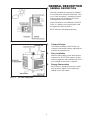
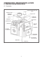
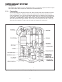
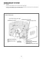
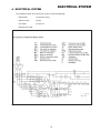
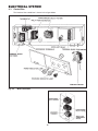
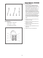
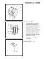
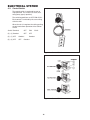
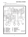
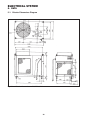
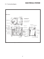
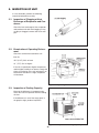
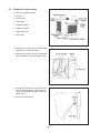
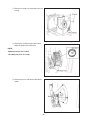
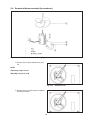
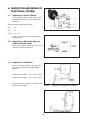
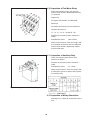
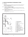
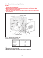
GENERAL DESCRIPTION
1. GENERAL DESCRIPTION
Generally speaking conventional air conditioners cool the entire enclosed environment. They
act as “heat exchangers”, requiring an interior
and an exterior unit (condenser) to exhaust
exchanged heat to the outdoors.
Unlike conventional air conditioners, the SPOT
COOL is a cooling system which directs cool
air to particular areas or objects.
SPOT COOL has the following features;
Fig. 1-1
Circuit of Auxiliary Relay
1)
Compact Design
The innovative design of SPOT COOL has
resulted in one compact design, replacing the
need for two separate units.
2)
Easy Installation
With the whole cooling system built into one
compact unit, SPOT COOL requires no pipe
work for refrigerant and installed easily. In this
case, cooling air duct work is required.
3)
Energy Conservation
SPOT COOL is economical because it cools
only the area or objects which need to be
cooled, not the entire room.
Fig. 1-2
Air Flow of Spot Cool
1
CONSTRUCTION, SPECIFICATIONS and DATA
2. CONSTRUCTION AND SPECIFICATION
2-1. Construction
Fig. 2-1
Construction of Hermetric Rotary Type Compressor
2
CONSTRUCTION, SPECIFICATIONS and DATA
1) Basic Construction
The SPOT COOL is compact in construction because the condenser and the evaporator are
enclosed in one unit. The interior is divided into two sections. The front face is equipped with the
evaporator and control box. The rear section contains the condenser and the compressor.
2) Air Flow (See Fig. 1-2)
1. Air flow for the condenser
Air is taken through apertures in the rear face and both sides of unit to cool the condenser and
discharged through the exhaust air duct at the top of unit.
2. Air flow for the evaporator
Air is taken from the front face of unit, cooled via the evaporator, and blown off from the aperture
in the unit top.
Using a cooling air duct (option, to be installed on the field), blow cool air against an object to be
cooled.
All air inlets are provided with air filters.
3
CONSTRUCTION, SPECIFICATIONS and DATA
2-2
Specifications
Item
Model
30HU
[Rating Condition]
DB 35˚C
95˚F
[Features]
Power frequency ..................................................... (Hz)
Line Voltage .......................................................... (Volt)
Power consumption ............................................... (Kw)
Current consumption .......................................... (Amp)
Power factor ........................................................... (%)
Starting current ................................................... (Amp)
Power wiring ....................................................... (AWG)
[Cooling Unit]
Cooling capability ............................................. (Kcal/h)
(Btu/h)
Cooling system
[Blower]
Type of fan
Air volume ........................................................... (m3/h)
(ft3/min)
Motor output .......................................................... (Kw)
[Compressor]
Type
Output .................................................................... (Kw)
Refrigerant
(kg)
Packed amount of refrigerant ................................ (lbs)
[Safety Device]
Overcurrent relays (for compressor, evaporator fanwith
motor and condenser fan motor)
Compressor overload relay
Fan motor protectors (for evaporator and condenser)with
High pressure switch
Anti-freezing thermostat
[Dimensions and Weight]
W x D x H .............................................................. (mm)
(inch)
Weight ..................................................................... (kg)
(lbs)
[Operating Conditions]
Inlet air
Fig. 2-1
Construction of Hermetric Rotary Type Compressor
4
WB28.2˚C
83˚F
(60%)
60
Three phase 220
4.7
70
88
70
12 (4-core)
9830
39000
Direct expansion
Sirroco fan
1800
1060
0.75
Hermetic
reciprocating type
2.2
R-22
2.0
4.4)0
with
with
with
12100 x 650 x 985
43.3 x 25.6 x 38.8
160
353
MAX. 45˚C (113˚F), 50%
MIN. 25˚C (77˚F), 50%
REFRIGERANT SYSTEM
3. REFRIGERANT SYSTEM
The component parts of the refrigerant system include the followings;
• Compressor
• Evaporator
• Condenser
• Modulating tank
• Capiliary tub
• High pressure switch
These parts are all connected by copper piping. All the connections have been brazed.
Fig. 3-1
Refrigerant system of MODEL 30HU
5
REFRIGERANT SYSTEM
3-1. Compressor
The compressor used for this unit is a reciprocating type. It is a hermetic compressor which incorporates a drive motor and a compression mechanism in an enclosed vessel.
3-1-1. Construction
The reciprocating type compressor consists of a drive section (motor) and a compressin mechanism as shown in Fig. 3-2. When the rotor shaft of motor rotates, the crank shaft causes the
piston to reciprocate in the cylinder and absorb and compress the refrigerant. Main components
are the motor, crank case, bearing, crank shaft, cylinder, piston, etc. The motor and compression
mechanism are supported by a spring inside the outer shell so that vibration of the compressor
does not transmit directly to the outside. The out shell is on the low pressure side, in which gas
flows from the evaporator. This gas cools the motor and compression mechanism.
Fig. 3-2
Construction of Hermetic Reciprocating Type Compressor
6
REFRIGERANT SYSTEM
3-1-2. Operation
1) Suction
When the piston is pushed down, pressure
inside the cylinder lowers. When this
pressure becomes less than the suction
side (low pressure side) pressure, the
suction valve at the top of the cylinder is
pushed open by the suction side pressure
and the refrigerant is sucked into the
cylinder. See Fig. 3-3.
Fig. 3-3
Suction
2) Compression
The refrigerant in the cylinder is pushed up
by the piston. As its capacity reduces, its
pressure increases gradually. See Fig. 3-4.
Fig. 3-4
Compression
3) Discharge
When the refrigerant pressure in the
cylinder becomes higher than the pressure
on the delivery side (hight pressure side) of
the compressor, the discharge valve opens
to deliver the compressed refrigerant to
the discharge side. See Fig. 3-5.
Fig. 3-5
Discharge
3-1-3. Lubrication of Compressor
In the lubrication system, lubricant from
the thrust pad hole enters an eccentric
hole in the crank shaft. Here, forced by
centrifugal force, the lubricant rises the
eccentric hole, enters the spiral groove in
the shaft, and rises while simultaneously
lubricating the bearing and subsequent
areas.
Fig. 3-6
Lubrication of Compressor
7
REFRIGERANT SYSTEM
3-2. Condenser
The condenser, which serves as a heat exchanger, has thin aluminum projections called spine fins
fastened toa copper tube. Heat is exchanged by forcing cooler air across the condenser fins.
3-3. Capillary Tube
The following table shows the specifications of the capillary tube.
Model Qty
Purpose of Use I.D, (mm)
Length (mm)
30HU
FOR COOLING Ø1.4±0.02
445
4
3-4. Evaporator
The evaporator is a heat exchanger using plate-fins and tubes. It is mounted at the front face of the
unit, located on the suction side of the blower.
8
REFRIGERANT SYSTEM
3-5. Modulating Tank
The modulating tank consists of a copper
pipe and tank sections, each being separated
from the other. The pipe connects to the
evaporator outlet at one end and to the
suction pipe of the compressor at the other;
the tank connects to the evaporator inlet.
The modulating tank is covered with a heat
insulator that eliminates thermal effects from
ambient temperature. It varies the quantitiy of
refrigerant in the refrigerating cycle for
optimum operating condition: it stores part of
refrigerant under light load and delivers
additiona refrigerant to the cycle under heavy
load.
Fig. 3-7
Modulating Tank
3-6. High Pressure Switch
The high pressure switch prevents the condenser and compressor from being damaged
by an excessively high pressure in the highpressure end of the refrigerating cycle, i.e.,
the refrigerant condensing pressure.
The switch is normally closed. The diaphragm
detects variations in pressure and, as the
pressure increases, the snap disk snaps back
to pucsh the pin down, causing the internal
contacts to open. This generates a signal to
open the auxiliary relay.
Possible causes of this trouble include:
1) The condenser air filter is seriously contaminated and clogged.
Fig. 3-8
2) Defective condense blower.
High Pressure Switch
9
REFRIGERANT SYSTEM
3-7. Piping
The parts of the cooling system are connected by copper pipe.
In the unit, the refrigerant cycle is enclosed. Each connection has been brazed. the circled portion in
the figure shows the parts which have been brazed.
Fig. 3-9
Refrigerant System Piping for MODEL 30HU
10
ELECTRICAL SYSTEM
4. ELECTRICAL SYSTEM
The component parts of the electrical system include the following:
• Control box
• Overcurrent relays
• Control switch
• Relays
• Fan motor
• Lamps etc.
• Compressor motor
Fig. 4-1
Electrical System for MODEL 30HU
11
ELECTRICAL SYSTEM
4-1. Control Box
The interior of the control box is shown in the figure below.
Fig. 4-2
Main Control Box
Fig. 4-3
12
Sub Control Box
ELECTRICAL SYSTEM
4-1-1. Auxiliary Relay
When the power is supplied to the unit,
this relay is energized across terminals 7
and 8 closed across terminals 5 and 3 and
across 6 and 4. These states remain
unchanged in all operation modes (FAN or
COOL). If one of the errors mentioned
below has occurred at the unit, the auxiliary relay is deenergized across terminals 7
and 8, and opened across terminals 5 and
3 and across 6 and 4. This shuts off power
to the fan motor relay and compressor
motor relay and accordingly brings the unit
to a stop. Also, the relay is closed across
terminals 6 and 2 to turn on the warning
lamp.
Fig. 1-1
1. Abnormally large current has flown in the
evaporator fan motor.
Circuit of Auxiliary Relay
Specifications
Rated Voltage:
AC230 volts
Rated current:
10 Amps
2. Abnormally large current has flown in the
condenser fan motor.
3. Abnormally large current has flown in the
compressor motor.
UL Recognized; file E43028
4. Compressor motor temperature has risen
abnormally.
5. High pressure has risen abnormally.
Fig. 1-1
Circuit of Auxiliary Relay
13
ELECTRICAL SYSTEM
4-1-2. Fan Motor Relay
This fan motor relay is closed when the
unit is in operation of FAN and COOL
mode, and supply power to the fan motor
of the evaporator. In the following case,
the relay opens to cut off power to the fan
motor.
When the auxiliary relay is opened by the
overcurrent relay OFF, compressor
overlaod relay OFF or high pressure switch
OFF.
Specifications
Rated Voltage:
AC230 Volts
Rated current:
15 amps
Fig. 4-6
Circuit of Fan Motor Relay
Fig. 4-7
Fan Motor Relay
Fig. 4-8
Circuit of Compessor Relay
UL listed file No.:E43028
4-1-3. Compressor Relay
This compressor relay is closed when the
unit is in operation of only COOL mode
and supply power to the compressor. In
the following case, the relay opens to cut
off power to the compressor.
When the auxiliary relay is opened by the
high pressure switch OFF, overcurrent
relay OFF or compressor overload relay
OFF.
When the evaporator is freezed. (Thermostat OFF)
Specifications
Rated Voltage:
AC230 Volts
Rated current:
30 amps
UL listed file No.:E43028
14
ELECTRICAL SYSTEM
Fig. 4-9
Compressor Relay
4-1-4. Overcurrent Relay
For three-phase blower motor and compressor motor, an overcurrent relay is
usually used as a safety device. The
overcurrent relay prevents motor coil from
burning if overcurent has flown into the
motor due to abnormal load applied to the
blower motor or compressor motor,
extraordinary change in supply voltage, or
loss of current in one phase. If overcurrent
flows into the heating coil would around
the bimetal strip, the bimetal strip curls,
thereby opening the output contact
(across terminals 95 and 96). This output
contact shuts off the auxiliary relay circuit
and brings the unit to a stop.
UL recognized:
Fig. 4-10
Internal Construction of Over Current Relay
File E78841
Current Setting
For compressor motor 16A
Fig. 1-1
For evaporator fan motor
2.8A
For condenser fan motor
2.0A
Circuit of Auxiliary Relay
15
ELECTRICAL SYSTEM
4-2. Control Switch
The control switch is employed to start or
stop operation. This switch is of 250V, 20A
rating rotary type (3-position).
The switching positions are OFF-FAN-COOL.
Each contact is switched by the cam uniting
with the shaft.
When the unit is hung from the ceiling, pulling
the pull cord allows operation of the control
switch.
Switch Terminals
OFF
FAN
(5) - (2) Conduct
OFF
OFF
(5) - (1) OFF
Conduct
(5) - (4) OFF
OFF
COOL
Conduct
Conduct
Fig. 4-12
Control Switch
Fig. 4-13
Control Switch
16
ELECTRICAL SYSTEM
4-3. Fan Motor
The fan motors are of three phase, induction
type.
The following table shows the specifications
of the fan motors.
When the control switch is set to FAN, the
evaporator fan motor rotates. When it is set to
COOL, both the evaporator and condenser
fan motors rotate.
Model/Spec.
Output (Watt)
Fig. 4-14
Rated Voltage (Volt)
For Evaporator 220
750
For Condenser 220
400
Rated
Fan Motor
4-4. Compressor Motor
The compressor motor is a three phase
motor. This motor is built in the compressor.
(Refer to 3-1.)
Specifications
17
Rated Voltage:
220V
Rated Output:
2200W
ELECTRICAL SYSTEM
4-5. Thermostat
When the evaporator has freezed, the contacts of thermostat open to stop the compressor and the
ventilating operation is automatically initiated. When the evaporator is unfreezed, the contacts close
to restart the compressor and the cooling operation is initiated.
The heat sensing tube of thermostat is mounted at the evaporator outlet tube and is insulated from
surrounding air by het insulating material. The setting of thermosate is fixed at -1.5˚C when the
contacts are open and at +14.5˚C when the contacts are closed.
Fig. 4-15
Thermostat
18
ELECTRICAL SYSTEM
4-6. Wiring
Power supplied cord is applied with 12AWG (4-core) wires.
Proper connections are indicated at all the wire ends. Faston type No. 250 or 187 terminals are
used.
Fig. 4-16
Wiring Diagram
19
ELECTRICAL SYSTEM
5. DATA
5-1. Exterior Dimensions Diagram
Fig. 5-1
Exterior Demensions of MODEL 30HU
20
ELECTRICAL SYSTEM
5-2. Construction diagram
Fig. 5-2
Construction Diagram of MODEL 30HU
21
ELECTRICAL SYSTEM
5-3. Cooling Capability Characteristics
1) Cooling Capability curve
Fig. 5-3
Cool Capability Curve
2) Current consumption curve
Fig. 5-4
Current Consumption Curve
22
ELECTRICAL SYSTEM
3) Cool air temperature difference curve
Fig. 5-5
Cool Air Temperature Difference Curve
4) Static pressure and air volum curve of cool air
Fig. 5-6
Static Pressure and Air Volume Curve
23
24
Repair
1. TROUBLESHOOTING .............................................................................. 24
2. INSPECTION OF UNIT ............................................................................ 26
3. DISASSEMBLY ....................................................................................... 27
4. INSPECTION AND REPAIR OF ELECTRICAL SYSTEM .............................. 34
5. INSPECTION AND REPAIR OF REFRIGERANT SYSTEM ........................... 38
6. REASSEMBLY ........................................................................................ 47
25
1. TROUBLESHOOTING
Before troubleshooting this system the following inspection should be performed.
a) Inspection of power source voltage and phase sequence
Check the voltage of the power source.
Model 30Hu: Three phase, 220 volt ± 15%, 6-Hz.
Check the operation and condition of the fuse or circuit breaker in the power source.
Check the rotating direction of blower. If the blower rotates in the opposite direction, phase
sequence of the power source is reverse.
Therefore, exchange two of the power cables connected to the power terminals R, S, and T.
b) Inspection of air filters
Remove the air filters and check the element. If it is dirty, wash it as described in the OPERATION
MANUAL.
The following chars are provided as a guide for categorized problem remedies. Detailed information is
contained in the following pages.
26
27
2. INSPECTION OF UNIT
In case of trouble, perform the following
inspection before disassembly.
2-1. Inspection of Clogging at Heat
Exchanger of Evaporator and Condenser.
Check the heat exchanger of the evaporator
and condenser for dier and clogging. If they
are dirty or clogged, remove and wash each
part.
Fig. 2-1
Spine Fins of the Condenser
Fig. 2-2
Operating Environment
Fig. 2-3
Inspection of Cooling Capacity
2-2. Examination of Operating Environment
Check the environment around the unit.
Inlet Air:
45˚C (113˚F), 50% or lower
25˚ (77˚F), 50% or higher
If the unit is operatied at higher temperature
and/or higher himidity than above, change the
place of installation. If the unit operated in an
environment outside this range, evaporator
will be frozen.
2-3. Inspection of Cooling Capacity
Measure the difference in temperature between the inlet of evaporator and the cooling
air duct.
If the difference is out of the range given in
teh graph at right, perform inspection.
28
3. DISASSEMBLY
[MODEL 30HU]
Fig. 3-1
Disassembly of MODEL 30HU
29
3-1. Removal of outer panels
1) Removal of following parts
1. Air filters
2. Exhaust duct
3. Front panel
4. Evaporator panel
5. Condenser panel
6. Right side panel
7. Rear panel
Fig. 3-2
Removal of Parts
Fig. 3-3
Removal of Control Box Cover
Fig. 3-4
Removal of Power Wire
2) Remove three screws from the control box
and open the control box cover.
3) Remove four screws from the sub-control
box and opent the sub-control box cover.
4) Remove four lead wires of the power wire
from the terminal block. Loosen the two
screws fixing conduit and disconnect the
power wire.
5) Remove left side panel.
30
3-2. Removal of Electrical Parts
1) Remove the electrical wiring according to the wiring diagram as shown below.
Fig. 4-16
Wiring Diagram
31
2) Remove the electrical partsk in the control box and sub-control box.
Fig. 3-6
Removal of Electrical Parts
3) Remove the control switch, power indicated lamp and warning lamp as shown.
Fig. 3-7
32
Removal of Control Switch
3-3.
Fig. 3-8
Removal of blower assembly (for evaporator)
Blower Assembly
33
1) Remove five wing nuts and remove the fan
casing.
Fig. 3-9
Removal of Blower Housing
Fig. 3-10
Removal of Sirocco Fan
Fig. 3-11
Removal of Blower Motor
2) Remove the set bolt using a box wrench
and their remove the sirocco fan.
NOTE:
Tightening torque for set bolt.
170~190kg-cm (12.5~13.7 ft-lb)
3) Remove four nuts and remove the blower
motor.
34
3-4. Removal of blower assembly (for condenser)
Fig. 2-1
Construction of Hermetric Rotary Type Compressor
1) Remove the nut (left handed screw) and
fan.
NOTE:
Tightening torque for nut.
450±50kg-cm (33±3.7 ft-lb)
Fig. 3-13
Removal of Fan
Fig. 3-14
Removal of Blower Motor
2) Remove four nuts and remove the blower
motor from bracket.
35
4. INSPECTION AND REPAIR OF
ELECTRICAL SYSTEM
4-1. Inspection of Control Switch
At each position of the control switch, there
should be continuity across the following
terminals..
Switch Position Conducting Terminals
OFF
2-5
FAN
1-5
Fig. 4-1
Inspection of Control Switch
Fig. 4-2
Inspection of Lamps
Fig. 4-3
Inspection of Condenser Fan Motor
Fig. 4-4
Inspection of Evaporator Fan Motor
COOL 1 - 5, 4 - 5
If there is no switch continuity, replace the
control switch.
4-2. Inspection of Warning Lamp and
Power Indicated Lamp.
Make a test circuit as shown in Fig. 4-2. If the
lamp fails to light up, replace it.
4-3. Inspection of Fan Motor
Measure resistance between the each terminals of the fan motor. (Except grounding
terminal.)
Condenser fan motor:
16.2 ± 2Ω (at 20˚C)
Evaporator fan motor:
5.9 ± 0.6Ω (at 20˚C)
If the resistance is not these standard values,
replace the fan motor.
36
4-4. Inspection of Thermostat
Check for coninuity across two terminals of
the termostat. At normal temperature, (17˚C
or higher) there is continuity across two
terminals.. If continuity is interrupted across
the terminals, replace the thermostat.
4-5. Inspection of High Pressure Switch
Check for continuity across two terminals of
the high pressure switch. At normal pressure
when the unit is stopped, there is continuity
across two terminals. If continuity is interrupted across the terminals, replace the high
pressure switch.
NOTE: Cut off pressure - 27.5kg/cm2G
(391PSIG)
Fig. 1-1
Reset pressure - 20.5kg/cm2G
(291 PSIG)
Circuit of Auxiliary Relay
4-6. Inspection of Comprssor Motor
Measure resistance across the terminals (R,
S, T) of the compressor motor.
Resistance:
1.13Ω ± 0.15Ω (at 20˚C)
1.07Ω (from Oct., 1986)
If the resistance is not this standard values,
replace the compressor.
Fig. 1-1
Circuit of Auxiliary Relay
4-7. Inspection of Over Load Relay.
The compressor has a built-in over load relay.
Check for continuity across tow terminals of
the overload relay.
At normal temperature, there is continutiy
across two terminals. If continuity is interrupted across the terminals, replace the
compressor.
Make check at the ambient temperature of
45˚C or less and more than 1 hour after
operation has been stopped.
Fig. 1-1
Circuit of Auxiliary Relay
37
4-8. Inspection of Compressor Relay
Check for continuity across the terminals
when the test button is depressed and/or
released.
Depressed:
All couples of terminals are conducted.
Released:
All couples of terminals are not conducted.
Measure the resistance across terminals A
and B.
Standard resistance:
650 ~ 800Ω
When the resistance is out of this range,
replace the compressor relay.
Fig. 4-8
Inspection of Compressor Relay
Fig. 4-9
Inspection of Over Current Relays
4-9. Inspection of over current relays
Check for continuity across the terminals 1 2, 3 - 4 and 5 - 6. These couples of terminals
are conducted via little resistance. At normal
condition (Non power source), there is continuity across terminals 96 and 95.
If these continuities are interrupted, replace
the overcurrent relay.
NOTE
1. Do not turn the dials of over current relays.
These dials of over current relays. These dials
have been factory adjusted.
2. These over current relays are automateic
resetting type.
38
4-10. Inpsection of Fan Motor Relay.
Check for continuity across the terminals
when the test button is depressed and when
it is released.
Depressed:
All couples off terminals are conducted
Released:
All couples of terminals are not conducted.
(Couples of terminals:
11 - 12, 13 - 14, 15 - 16 and 19 - 20.)
Measure the resistance across termianls A
and B.
Standard resistance:
Fig. 4-10
Inspection of Fan Motor Relay
1900~2100Ω.
When the resistance is out of this range, and/
or all couples of terminals are not conducted
when the test button is depressed, replace
the fan motor relay.
4-11. Inspection of Auxiliary Relay
Check for continuity between the each
terminals as follows.
Measure the resistance across terminals 7
and 8.
Standard resistance:
14 ~ 16 kΩ.
When the resistance is out of this range, and/
or continuties are not as above table, replace
the auxiliary relay.
Fig. 4-11
Inspection of Auxiliary Relay
4-12. Inspection of Wiring Connection
Refering to 3-2, check for connection of each
wire.
39
5. INSPECTION AND REPAIR OF REFRIGERANT SYSTEM
5-1. Inspection
When something is wrong with the refrigerant system, it fails to cool sufficiently. the possible cause
of this failure is clogging, leakage or insufficient refrigerant. In such a case, inspect the system
according to the following procedure.
5-1-1. Inspection of Refrigerant Clogging
Check the component parts of the refrigerant system and the pipes connecting them for clogging. If clogged with refrigerant, only the clogged part is frosted partially. In such a case, change
the part in question.
5-1-2. Inspection of Refrigerant Leak
Carefully check all connections, and each component for leaks whenever the refrigerant system is
installed or repaired.
Use the gas leak tester to inspect the system.
Fig. 5-1
Gas Leak Tester
40
The gas leak tester should be used in the following way.
1) Check the amount of propane liquid in the container.
2) Install the propane container to the gas leak tester body by turning it fully clockwise.
3) When lighting the tester, insert the match into the ignigting hole of the tester and turn the adjusting handle slowly counterclockwise. This will ignite the gas leak tester.
4) The reactor (copper ring) must be red heat, but the flame must be kept as small as possible. The
smaller the flame, the more sensitive.
5) Hold the tip of the sensing tube at each suspected leak.
6) Watch for a change in the flame color.
If there is no leak, the flame will be almost colorless.
The slightest leak will be indicated by a brightly colored flame
Color of flame:
When leak is very small Color of flame is light green.
When leak is large
Color of flame is bright blue.
When leak is very large Color of flame is purple.
NOTE:
a) Always hold the tester vertically when detecting a leak.
b) Use adequate ventilation, burned R-22 is poisonous and should not be inhaled.
c) Never make a gas leak check near flammable materials.
5-1-3. Insufficient Refrigerant
In case there is a leak, clogging or trouble in the refrigerant system of the Spot Cool replace or
repair the part in question. All the connections of the refrigerant system have been brazed. When
removing or reassembling these connections, they must by brazed.
5-2. Repair of Refrigerant System
In case there is a leak, clogging or trouble in the refrigerant system of the Spot Cool replace or repair
the part in question. All the connections of the refrigerant system have been brazed. When removing
or reassembling these connections, they must be brazed.
5-2-1. Correct Brazing Work
It is desirable to use a slightly reducing flame. Normally, often used is an oxy-acetylene flame
which is easy to judge and adjust the condition of the flame. Unlike gas welding, a secondary
flame is used for brazing.
It is necessary to preheat the base metal proerly depending on the shape, size or thermal conductivity of the brazed fitting.
The most important point in flame brazing is to bring the whole brazed fitting to a proper brazing
temperature. It is also important to take care not to cause overflow of brazing filler metal, oxidization of brazing filler metal, or deterioration due to the overheating of flux.
41
(1)
Proper Fitting, Proper Clearance
In general, the strength of brazing filler metal
is lower than that of the base metal. So, the
shape and clearance of the brazed fitting are
quite important.
As for the shape of the brazed fitting, it is
necessary to maximize its adhesive area. The
clearance of the brazed fitting must be
minimized to pour brazing filler metal into it
by use of capillary attraction.
Fig. 5-2
(2)
Brazed Fitting and Its Clearance
Cleaning of Brazing Filter Metal and Pipe
When the refrigerant cycle is exposed by heating, brazing filler metal may be found sticking to the
inside and outside of the pipe. Brazing filler metal may also be compounded with oxygen int he air to
form oxide film. Fats and oils may stick to the pipe.
In such conditions, complete brazing cannot be made. It is necessary to get rid of brazing filler metal
completely by using sand paper or a solvent such as trichlene.
(3)
Use of Dry Nitrogen Gas
During brazing, the inside of the pipe undergoes oxidative reaction due to the brazing flame. Conduct dry nitrogen gas (11/min;adjust with the flow regulator) through the pinch-off tube of the refrigerant cycle to prevent oxidization.
(4)
(5)
Take care not to allow dirt, water, oil, etc. to enter into the pipe.
Vertical Joint
Heat the whole brazed fitting to a proper brazing temperature. Make the brazing filler metal contact
with the fitting so that the brazing filler metal starts flowing by itself. Stop heating the fitting as soon
as the brazing filler metal has flown into the clearance. Since the brazing filler nmetal flows easily
into the portion heated to a proper temperature, it is essential to keep the whole fitting at a proper
brazing temperature.
Fig. 5-3
Vertical Down Joint
Fig. 5-4
42
Vertical Up Joint
5-2-2. Removal of Refrigerant Cycle Relatives
CAUTION:
1. When removing the brazed portion, protect the other parts with a steel plate, asbestos, etc. to
keep the other parts from the flame.
2. Before removing the refrigerant cycle from the brazed portion, be sure to cut off the end of
pinch-off tube and bleed the cycle of gas.
3. In this case, also bleed the refrigerant cycle of N2 gas through the open pinch-off tube in order to
prevent oxidization.
Fig. 5-5
Refrigerant Cycle of MODEL 30HU
[Exchanger and Brazing Removing Portions]
Exchanger
Brazing Removing Portions
Compressor
A-B
Condenser
A-C
Capillary tube
D-F
Evaporator
D-E
NOTE:
1. Evaporator include the capilliary tube.
2. Hold the compressor body, not the tubes, when carrying the compressor.
43
5-3. Charging the System with R-22
Be sure to purge the system and charge the system with refrigerant to the specified amount in the
following.
CAUTION:
1) When handling refrigerant (R-22), the following precautions should be observed.
A) Always wear eye protection while handling refrigerant.
B) Keep the refrigerant container blow 40˚C (104˚F).
C) Do nnot handle refrigerant in an enclosed room.
D) Do not handle refrigerant near an open flame (especially never while smoking a cigarette).
E) Discharge refrigerant slowly, when purging a system.
F) Be careful the liquid refrigerant does not contact skin.
2) If liquid refrigerant strikes eye or skin.
A) Do not rub the eye or skin.
B) Splash large quantities of cool water on the eye or skin.
C) Apply clean petroleum jelly to the skin.
D) Rush to physician or hospital for immediate professional treatment.
E) Do not attempt to treat it yourself.
5-3-1. Connection of Gauge Manifold
(1) Cut off the crushed end of the pinchoff tube at the high pressure side of
the refrigerant cycel with a pipe cutter.
(2) Fit the process tube fitting to the
pinch-off tube on both sides.
Fig. 5-6
44
Mounting of process tube Fitting
(3) Connect the charging hoses (red one
on high pressure side, and blue one on
low pressure side) of the gauge
manifold to the process tube fittings.
NOTE: Connect the hoses using care not to
mistake the high pressure side for the low pressure side and vice versa.
(4) Connect the charging hose (green) at
the center of the gauge manifold to the
vacuum pump.
Fig. 5-7
Connection of Gauge Manifold
5-3-2. Purging
(1) Open the high pressure valve (HI) and
the low pressure valve (LO) of the
gauge manifold.
(2) Turn on the vacuum pump to start
purging. (Purge the system for approx.
15 minutes.)
(3) When the negative pressure gauge
reading (degree of vacuumization)
reaches 750 mmHg or larger, close the
high pressure valve and the low
pressure valve of the gauge manifold
and turn off the vacuum pump.
Fig. 5-8
Purging
5-3-3. Checking Airtightness
(1) Leave the high pressure valve and the
low pressure valve of the gauge
manifold closed for five minutes or
more, and confirm that the gauge
pointer does not return to zero.
(2) In case the gauge pointer returns
gradually to zero, there must be a leak
somewhere. In such a case, first
correct the brazed portion.
Purge the system once more, and
confirm there is no leak.
Fig. 5-9
Checking Airtightness
45
5-3-4. Checking Gas Leak
(1) Remove the charging hose (green)
from the vacuum pump, and connect
the hose to the refrigerant cylinder
(R22).
NOTE: Before this stip, fit the mouthpiece for
refrigerant cylinder (service tool: No. 945502050)
to the outlet of the refrigerant cylinder.
Fig. 5-10
Purging Air inside Charging Hose
Fig. 5-11
Charging with Refrigerant for Gas
Leak Check
(2) Loosen the nut on the gauge manifold
sid e fo the charging hose (green).
Open the valve of the refrigerant
cylinder to purge air from inside the
charging hose. (As soon as a “hissing”
sound is heard, tighten the nut as it
was before.)
(3) Open the high pressure valve of the
gauge manifold. Charge the system
with refrigerant until the low pressure
gauge indicates 75 PSIG. (4 kg/cm2G).
After charging is complete, close the
high pressure valve.
(4) Check carefully for gas leak inside the
refrigerant cycle using the gas leak
tester.
(5) Correct (braze) leaking portions, if any.
CAUTION:
Before checking for gas leak, fully confirm that
there is nothing flammable in the area to cause
an explosion or fire. Since contact of refrigerant
with an open fire generates toxic gas (phosgene),
take care not to breathe it.
46
5-3-5. Purging (Repeat)
(1) Close the valve of the refrigerant
cylinder. Then remove the charging
hose (green) from the refrigerant
cylinder, and connect it to the vacuum
pump.
NOTE: Keep the high pressure valve and the low
pressure valve of the gauge manifold closed.
(2) In the procedure of above “5-3-2.),
purge the system until the low pressure gauge indicates 750mmHg or
larger. (For 15 minutes or more.)
(3) After purging is complete, close the
high pressure valve and the low
pressure valve of the gauge manifold..
Fig. 5-12
Purging (Repeat)
CAUTION:
Be sure to purge the system twice or more using
the repetitive vacuum method.
Purge the system an additional time on rainy or
humid days.
5-4. Refrigerant Charging Work
5-4-1. Refrigerant charging
(1) Remove the charging hose (green)
from the vacuum pump, and connect it
to the refrigerant cylinder (R-22).
(2) Loosen the nut on the gauge manifold
side of the charging hose (green).
Open the valve of the refrigerant
cylinder, and purge the air from inside
the charging hose.
Fig. 5-13
Purging Air Inside Charging Hose
NOTE: At this time, tighten the nut as soon as
the air comes out with a “hissing” sound.
47
(3) Place the refrigerant cylinder on a
scale. (weighting capacity: 70lbs;
graduated in 0.2 oz.)
(4) Open the high pressure valve of the
gauge manifold and the valve of the
refrigerant cylinder.
Charge the system with refrigerant to
the specified amount, looking at the
graduations of the scale.
[Specified Charging Amount of Refrigerant]
Fig. 5-14
If the system cannot be charged with
specified amount of refrigerant under this
condition, follow the steps below:
1. Close the high-pressure valve of
manifold.
2. Run the system.
3. Slowly open the low pressure valve
while looking at the scale reading.
4. When the scale reads the specified
amount, immediatey close the lowpressure valve.
5. Bring the system to a stop.
CAUTION:
The charging amount of refrigerant has a great
effect on the colling capacity of the cooler for
business use. Charge to the specified amount,
always looking at the scale graduations.
(5) Close the high pressure valve of the
gauge manifold and the valve of the
refrigerant cylinder.
48
Charging with Refrigerant
5-4-2. Removal of Gauge Manifold
(1) Pinch off the pinch-off tube with a
pinch-off tool.
(2) Remove the gauge manifold and the
process tube fitting. Crush the end of
the pinch-off tube.
(3) Braze the end of the pinch-off tube.
(4) Make sure that gas leak is not observed at the pinched off portion and
the brazed end.
6. REASSEMBLY
Reassemble the unit in the reverse order of
removal.
Fig. 5-15
Described below are the parts that need
special care in reassembling the unit. Perform
wiring in reference to the wiring diagram.
Removal of Gauge Manifold
(1) Compressor Mounting
Mount the compressor on the frame, using
cushion, collar steel, spring washer, plate
washer and nut.
(2) Blower Assembly Mounting
1. Mounting of blower fans (for evaporator).
Tightening Torque:
Fig. 6-1
1.3 ± 0.7 lb•ft (1.8 ± 0.1 kg•m).
Compressor Mounting
NOTE:
1) After reassembling, the gap between evaporator fan and casing should be 0.06 inches
(1.5 mm) or more.
2) After reassembling, the gap between condenser fan and exhaust duct should be 2.0
inches (5 mm) or more.
(3) Wiring Notice
Fix the wires with clamps so that they do not
come into contact with the edges of structure, etc.
Set the wire with clamps at the same positions they were before removal.
(4) Perform Test
Perform the inspection of cooling capacity in
2-3., and check for abnormal noise or abnormal vibration.
Fig. 6-2
Blower Assembly Mounting
49
50