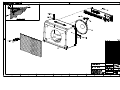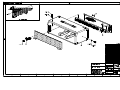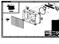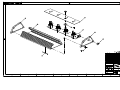
1
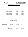
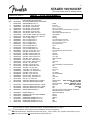
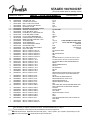
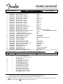
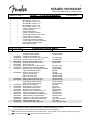
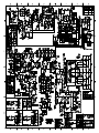
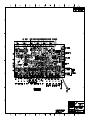
1
STAGE® 100/160 DSP
(This is the model name for warranty claims)
p/n 2267000020 / 2268000020 (120V)
Head Version p/n 2269000010 (120V)
SERVICE MANUAL
CONTENTS:
Notices .............................. 2
Specifications.................... 3
Service Notes.................... 4
Circuit Description............. 5
Parts Lists:
PCB Assembly............ 6
uDSP Assembly ......... 8
Chassis Assembly ...... 9
Cabinet Assembly .... 10
End Item Assembly .. 10
Footswitch Assembly 11
Service Diagrams ........... 12
Fender® Musical Instruments Corp. 8860 East Chaparral Road Suite 100 Scottsdale, AZ 85250
2
STAGE® 100/160 DSP
(This is the model name for warranty claims)
June, 2002
IMPORTANT NOTICE
• Copyright © 2002 FMIC. All rights reserved. All
information contained herein is CONFIDENTIAL
and PROPRIETARY and is the property of
Fender® Musical Instruments Corporation. It is
not to be sold or assigned to another party and is
disclosed solely for use by Fender Authorized
Service Centers for purposes of product service
and maintenance. All information is not to be disclosed to others without the expressed permission
of Fender® Musical Instruments Corporation. All
specifications are subject to change without notice. This information and any copies produced
electronically or otherwise must be surrendered
upon demand of Fender Musical Instruments Corporation.
• Parts marked with two asterisks (**) indicate the
required use of that specific part. This is necessary for RELIABILITY and SAFETY requirements.
DO NOT USE A SUBSTITUTE!
PARTS LIST CODES
The description codes used in the itemized Parts Lists are defined below:
CAPACITOR CODES
HARDWARE CODES
CAP AE
CAP CA
CAP CD
CAP MPF
CAP MY
CAP PFF
BLX
CR
HWH
M
NI
OHP
PB
PHP
PHPS
SMA
SMB
SS
TF
ZI
=
=
=
=
=
=
Aluminum Electrolytic
Ceramic Axial
Ceramic Disk
Metalized Polyester Film
Mylar
Polyester Film/Foil
RESISTOR CODES
RES CC
RES CF
RES FP
RES MF
RES WW
=
=
=
=
=
Carbon Comp
Carbon Film
Flame Proof
Metal Film
Wire Wound
=
=
=
=
=
=
=
=
=
=
=
=
=
=
Black Oxide
Chrome Plated
Hex Washer Head
Machine Screw
Nickel Plated
Oval Head Phillips
Particle Board
Pan Head Phillips
Pan Head Phillips Sems
Sheet Metal "A" Point
Sheet Metal "B" Point
Stainless Steel
Thread Forming
Zinc Plated
3
STAGE® 100/160 DSP
(This is the model name for warranty claims)
SPECIFICATIONS
Model Name:
Stage 100 DSP
Stage 160 DSP
Stage 100H DSP
(Head Version)
Release Number:
(Not model numbers)
PR 501
PR 501
PR 501
Part Numbers
2267000020
2267001020
2267003020
2267004020
2267005020
2267006020
2267007020
2267009020
2268000020
2268001020
2268003020
2268004020
2268005020
2268006020
2268007020
2268009020
2269000010
2269001010
2269003010
2269004010
2269005010
2269006010
2269007010
2269009010
(120V, 60Hz) US:
(110V, 60Hz) TW:
(240V, 50Hz) AUS:
(230V, 50Hz) UK:
(230V, 50Hz) ARG:
(230V, 50Hz) EUR:
(100V, 50/60Hz) JPN:
(220V, 60Hz) ROK:
(For all Models)
Power Requirement:
400W
Power Output:
100W RMS into 8 ohms @ 5%THD
160W RMS into 4 ohms @ 5%THD
Power Amp Sensitivity:
620mV for 100W into 8 ohms @ 5%THD
810mV for 160W into 4 ohms @ 5%THD
Impedances
Speaker Complement:
Dimensions
Weight:
Input (Pre-Amp): 1M ohms
Pre Amp Out: 1k ohms
Pwr Amp In: 10k ohms
One (1) 12", 8 ohm,
Celestion G12T-100
(P/N 0054420000)
Height: 17.5 in (45 cm)
Width: 22.4 in (57 cm)
Depth: 10.2 in (26 cm)
42 lbs (19.1 kg)
Two (2) 12”, 8 ohm,
Celestion G12T-100
(P/N 0054420000)
-NA-
18.5 in (47 cm)
26.1 in (66 cm)
10.3 in (26 cm)
8.5 in (22 cm)
22.4 in (57 cm)
9.5 in (24 cm)
53 lbs (24.1 kg)
24 lbs (10.9 kg)
Product specifications are subject to change without notice
4
STAGE® 100/160 DSP
(This is the model name for warranty claims)
SERVICE NOTES
1. CHASSIS REMOVAL is accomplished by first
removing two (2) screws from the cabinet side
panel and four (4) screws from the top of the
cabinet; disconnect the ¼” speaker plug(s) from
the speaker jack(s) and then slide the chassis
toward the rear of the cabinet.
2. uDSP PCB ASSEMBLY REMOVAL is accomplished by disconnecting the ribbon cable on
the PCB Assembly, releasing the tabs on each
of the plastic stand-offs which the PCB assembly is mounted. Removal of the uDSP PCB
assembly may be necessary should any of the
Digital Effects operate improperly.
attached from the bottom of the chassis. Disconnect the transformer and primary leads at
P1-P14. Disconnect the breakaway PCB ribbon cable at P20 and speaker wires (blk/wht) at
P15-P16. Disconnect the ribbon cable to uDSP
assembly at P19. Remove the power LED from
the jewel assembly.
4. STAGE 100/160 DSP BREAKAWAY PCB REMOVAL is accomplished by removing five (5)
nuts and washers at the jacks and two (2)
screws at the XLR jack. Disconnect the ribbon
cable from the main PCB at P20 and the
speaker wires (blk/wht) at P15-P16.
3. STAGE 100/160 DSP MAIN PCB REMOVAL is
accomplished by removing the following items:
All knobs including washers and nuts (14) , one
(1) input jack nut and washer, (1) screw near
mains fuse, seven (7) screws at the heatsink
PCB EXCHANGE POLICY
Parts marked with a single asterisk (*) in the Part
Lists (starting on page 10) are not field replaceable.
If a failure due to one of these components is detected, please contact the Fender® Dealer
Customer Service Department to order the complete PCB Assembly.
5
STAGE® 100/160 DSP
(This is the model name for warranty claims)
CIRCUIT DESCRIPTION
This section provides an overview of any new or
unusual circuitry incorporated into this amplifier
model. The purpose is to aid the service technician
by providing insight into the design areas most
likely to present a challenge in troubleshooting.
This overview is focused for the efficient use and
security of Fender® proprietary information.
Thermistor RT2 monitors the heatsink temperature.
Its resistance increases with temperature and at
approx. 100 ºC turns on xstr Q23. This shorts out
C77, turning on FET Q22 providing a muting function at the power amp input. The amplifier remains
muted until the heatsink cools down, at which point,
normal operation is restored.
PRE-AMPLIFIER
POWER SUPPLY
The guitar input signal is fed into the high pass filter
at U1–A before splitting into two signal paths. The
normal channel signal path (U1–B to U3–B) is active until FETs Q2, Q4, and Q6 are turned on
activating the drive channel signal path (U2–A to
U3–B). Turning on FETs Q1, Q3, and Q5 activates
the “More Drive” channel signal path for increased
gain and sustain. Differential amp U8–A and follower U8–B adjust the signal level and provides
+1.65VDC bias voltage to the uDSP effects card.
The preamp is in series with the digital effects card,
therefore, disconnecting the card breaks the overall
signal path. The low pass filter at U5–B recovers
the signal from the uDSP card and sends it to the
external effects loop and power amplifier.
Standard bridge rectifiers for both high and low
voltage sections, with zener regulation (D52–53) for
the +/–16V supplies. Half–wave rectifier (D46–47,
C48) supplies U11, 7805 regulator for +5V supply
for the uDSP card and digital user–interface.
POWER AMPLIFIER
“Flying Rail” power amp topology. The output stage
is referenced to ground, and the output signal is derived from the center tap of the high voltage power
supply (C86 & C87) which is floating. Diff–amp U7–
B amplifies voltage developed at the load sense resistors (R120–123) to provide negative current
feedback. Inserting an 8Ω load at Ext. Spkr (J7)
turns on FET Q20 creating an attenuation network
(R117–119) to compensate for the increased current at 4Ω total load impedance. This allows the
amplifier to have a similar frequency response running either an 8 or 4Ω speaker load.
.
DIGITAL USER INTERFACE
The uDSP effects card generates clock signals HD0
(~45Hz) and HD1 (~90Hz) which control the 4053
CMOS switch to read pots R134, R135, and R138.
The DC level (0–5V) of the pots controls the reverb
level, fx level, and fx time/rate. Power (+3.3V) is
switched to encoders S4 and S5 via the 4053, also
controlled by HD0. The outputs of the 4–bit encoders, isolated by diodes D28–D35, determine the
active reverb and fx algorithms (HD4–HD7).
DIGITAL NOISE
The uDSP effects card generates some high frequency noise (>50kHz), which is a normal product
of DSP processing. This noise is not audible and
does not effect amplifier performance, but may be
visible when observing the output of the amplifier on
an oscilloscope.
6
STAGE® 100/160 DSP
(This is the model name for warranty claims)
PARTS LIST:
MAIN – PCB ASSEMBLY
QTY.
1
1
REF
1
2
3
4
10
3
7
3
2
2
6
6
5
4
1
1
3
12
4
2
2
3
3
1
2
1
10
1
2
2
1
4
4
1
2
1
3
5
PART #
0057616004
*
0057619000
0048914000
0033606003
0028458003
0028459003
0028467003
0028471003
0028474003
0055780000
0028031000
0039256001
0038699001
0039259001
0038701001
0039263001
0051445003
0051457003
0051406003
0034788003
0027255003
0027257003
0027259003
0027261003
0027264003
0030950003
0030953003
0051416003
0027272003
0027275003
0027278003
0052003003
0053860000
0027281003
0027286003
0030950003
0030953003
0051416003
0027940000
0027941000
DESCRIPTION
**PCB ASSY STAGE 100/160 DSP
PCB FAB STAGE 100/160 DSP
SVC DIAG COMB STAGE 100/160 DSP
CABLE RIBBON 8 CKT 7"
CAP AE RDL .47uF 50V 20%
CAP AE RDL 1uF 50V 20%
CAP AE RDL 2.2uF 50V 20%
CAP AE RDL 22uF 50V 20%
CAP AE RDL 47uF 50V 20%
CAP AE RDL 100uF 25V 20%
**CAP AE RDL 1000uF 35V 105C 20%
CAP AE RDL 3300uF 63V +100%-20
CAP CA 68pF 100V LL
CAP CA 100pF 100V LL
CAP CA 220pF 100V LL
CAP CA 470pF 50V LL
CAP CA 1000pF 50V LL
CAP CD 22pF 500V 5%
CAP CD 100pF 500V 5%
CAP CD 220pF 500V 10%
CAP CR .1uF 50V 20% .2" LS
CAP MPF .001uF 100V 10%
CAP MPF .0022uF 100V 10%
CAP MPF .0033uF 100V 10%
CAP MPF .0047uF 100V 10%
CAP MPF .01uF 100V 10%
CAP PFF RDL .022uF 50V 5%
CAP PFF RDL .039uF 50V 5%
CAP SF .1uF 100V 10%
CAP MPF .047uF 63V 10%
CAP MPF .068uF 100V 10%
CAP MPF .1uF 63V 10%
**CAP MPF .1uF 250V 10%
**CAP MPF .1uF 250VAC 20%
CAP MPF .22uF 63V 10%
CAP MPF .47uF 63V 10%
CAP PFF RDL .022uF 50V 5%
CAP PFF RDL .039uF 50V 5%
CAP SF .1uF 100V 10%
CONTROL SNAPIN 50k 15A TAPER
CONTROL SNAPIN 50k B TAPER
2
1
1
52
0027947000
0027949000
0054390000
0006260001
CONTROL SNAPIN 100k 30C TAPER
CONTROL SNAPIN 250k 30C TAPER
CONTROL SNAPIN 5k 15A TAPER
DIODE 1N4448 SIGNAL LL
9
4
2
3
1
1
2
0064089001
0029045000
0054210001
0027329001
0031635001
0031019001
0028119000
DIODE 1N4003 LL
DIODE 6A 400V 6A4 LEAD FORMED
DIODE BAT85
DIODE ZEN 1N5228B 3.9V 5% LL
DIODE ZEN 1N5240B 10V 5% LL
DIODE ZEN 1N5245B 15V 5% LL
DIODE ZEN 1N5353B 16V 5W 5%
(continued)
REFERENCE DESIGNATION
PW20
C16 C47
C14 C75 C77
C6 C17 C53 C70
C8 C10 C19 C31 C39-40 C46 C81 C110-111
C51 C102-103
C50 C55-56 C84-85 C100-101
C78 C82-83
C86-87
C44-45
C7 C30 C32 C41-42 C115
C35 C37 C62-63 C117-118
C9 C15 C43 C119 C121
C3 C18 C22 C27
C116
C94
C66-67 C95
C57-58 C68-69 C79-80 C104-109
C71-74
C59-60
C23 C48
C1-2 C24
C28 C54 C122
C34
C33 C36
C61
C11 C20 C64-65 C76 C92 C96-99
C49
C25-26
C112-113
C114
C5 C89-91
C4 C52 C88 C93
C34
C33 C36
C61
R10 R16 R34
BASS, VOLUME, (DR) VOLUME
R9 R38
TREBLE, (DR) MID
R134-135 R138
REV LVL, TIME/RATE, FX LVL
R27 R42
DRIVE, (DR) TREBLE
R45
(DR) BASS
R11
MID
D1-8 D11-18 D21-24 D27-39 D41-44 D58-59
D63 D65 D67 D70-77 D79-80
D25-26 D40 D46-51
D54-57
D19-20
D60-62
D64
D66
D52-53
* Non-serviceable part. Replace complete parent assembly. See PCB EXCHANGE POLICY on page 4.
Unique Fender® part. Order directly from the Fender® dealer Customer Service Department.
** Safety Requirement part. Replacement must match Safety Agency…–Value, if specified –Type, if specified –Approval Mark(s) if on part.
** Both a unique Fender® part and a Safety Requirement part as defined above.
7
STAGE® 100/160 DSP
(This is the model name for warranty claims)
PARTS LIST:
MAIN – PCB ASSEMBLY
QTY.
2
16
2
1
1
1
1
6
1
1
8
2
1
1
3
3
1
1
2
1
4
1
4
1
1
10
10
10
2
5
2
6
2
1
19
PART #
0041074000
0025802000
0020775000
0027416000
0057350000
0025796000
0054259000
0032908000
0016795000
0028120000
0031611000
0041261000
0041812000
0027387000
0051658000
0053450000
0054261000
0040271000
0049948000
0055812000
0024947001
0024954001
0024956001
0029604001
0024961001
0024965001
0024969001
0024971001
0024972001
0024973001
0024977001
0028034001
0024979001
0024980001
0024981001
DESCRIPTION
ENCODER 16-POS 4-BIT BINARY
FASTON TAB, .250"
**FUSE CLIP PCB 5mm
HDR .1 CTR 8 CKT SQ PIN
HDR .1 CTR 8x2 CKT SQ PIN
HEATSINK TO-220
HEATSINK PLATE STAGE 100/160
SCRW TF 6-32x3/8 PHP ZI
IC OP-AMP DUAL TL072
IC 4053B TPL 2 CHAN ANLG SW
IC OP-AMP DUAL PC4560
IC VOLT REF LM4040DIZ-10.0
IC REGULATOR +5V MC7805CT
INDUCTOR AIR CORE RDL 2.5uH
JACK MONO R/A
JACK STEREO R/A
JACK XLR MALE RT ANGLE
LED RED/YELLOW
LED, RED LONG LEAD LUMEX
LED TULIP ASSY
RES CF 1/4W 5% 47ohm LL
RES CF 1/4W 5% 150ohm LL
RES CF 1/4W 5% 220ohm LL
RES CF 1/4W 5% 300ohm LL
RES CF 1/4W 5% 470ohm LL
RES CF 1/4W 5% 1k LL
RES CF 1/4W 5% 1.5k LL
RES CF 1/4W 5% 2.2k LL
RES CF 1/4W 5% 2.7k LL
RES CF 1/4W 5% 3.3k LL
RES CF 1/4W 5% 4.7k LL
RES CF 1/4W 5% 5.1k LL
RES CF 1/4W 5% 6.8k LL
RES CF 1/4W 5% 8.2k LL
RES CF 1/4W 5% 10k LL
2
7
10
5
6
1
21
0024985001
0024987001
0024988001
0024989001
0024993001
0024995001
0024997001
RES CF 1/4W 5% 15k LL
RES CF 1/4W 5% 22k LL
RES CF 1/4W 5% 27k LL
RES CF 1/4W 5% 33k LL
RES CF 1/4W 5% 47k LL
RES CF 1/4W 5% 68k LL
RES CF 1/4W 5% 100k LL
2
3
2
5
2
1
10
0025058001
0025059001
0025061001
0025065001
0028018001
0025068001
0025069001
RES CF 1/4W 5% 180k LL
RES CF 1/4W 5% 220k LL
RES CF 1/4W 5% 330k LL
RES CF 1/4W 5% 470k LL
RES CF 1/4W 5% 510k LL
RES CF 1/4W 5% 820k LL
RES CF 1/4W 5% 1M LL
1
1
0031767001
0047750001
RES CF 1/2W 5% 15ohm LL
RES CF 1/2W 5% 330ohm LL
(continued)
REFERENCE DESIGNATION
S4-5
P1-16
@ F1
P20
P19
@ U11
REV SELECT, FX SELECT
@ HEATSINK
U1
U10
U2-9
D68-69
U11
L1
J2-3 J6
FTSW, PRE AMP OUT, MAIN SPKR
J1 J4 J7
INPUT, PWR AMP IN, EXT. SPKR
J5
LINE OUT
DRIVE STATUS
D78
DISTORTION
D9-10
POWER
D45
R7 R196-197 R203
R81
R87 R94 R198-199
R80
R36
R20 R85 R95-96 R118-119 R127 R131 R151 R202
R24 R98-99 R102-103 R106-107 R132 R162 R181
R17 R49-50 R66-67 R82 R84 R89 R92 R117
R90-91
R28 R76 R88 R93 R133
R47 R77
R4 R25 R68-71
R5 R14
R23
R26 R33 R51-53 R62-63 R97 R115-116 R129
R136-137 R139 R143-144 R183 R185 R193
R1 R6
R8 R12 R21-22 R48 R150 R153
R59-60 R64-65 R72-75 R113-114
R29 R40 R43 R46 R176
R32 R37 R39 R78-79 R195
R44
R18-19 R35 R41 R54 R61 R83 R86 R128 R130
R145-148 R165 R172 R182 R188-190 R200
R13 R55
R15 R31 R180
R175 R184
R30 R159 R169 R171 R174
R2-3
R168
R149 R152 R166 R170 R173 R177 R186-187
R194 R201
R126
R154
* Non-serviceable part. Replace complete parent assembly. See PCB EXCHANGE POLICY on page 4.
Unique Fender® part. Order directly from the Fender® dealer Customer Service Department.
** Safety Requirement part. Replacement must match Safety Agency…–Value, if specified –Type, if specified –Approval Mark(s) if on part.
** Both a unique Fender® part and a Safety Requirement part as defined above.
8
STAGE® 100/160 DSP
(This is the model name for warranty claims)
PARTS LIST:
QTY.
1
1
4
1
1
4
2
1
2
1
2
1
3
2
2
6
3
3
1
1
11
3
8
1
1
3
3
7
6
6
2
10
23
1
PART #
0027872001
0026549001
0039209001
0027627001
0031067001
0027632001
0015582001
0025816001
0016971001
0017191001
0017372001
0016979001
0055781001
0027628001
0028021001
0028028000
0028091000
0048451000
0051418003
0026411000
0014689003
0016739003
0016742003
0051447003
0051448003
0028114000
0028115000
0027638000
0028169000
0040903000
0020888001
0020888001
0020888001
0052457000
DESCRIPTION
RES CF 1/2W 5% 1.2k LL
RES CF 1/2W 5% 1.5k LL
RES FILM 1W 5% .22ohm LL
RES FILM 1W 5% 10ohm LL
RES FILM 1W 5% 750ohm LL
RES MF 1/4W 1% 2.43k LL
RES MF 1/4W 1% 10.0k LL
RES MF 1/4W 1% 20.0k LL
RES MF 1/4W 1% 33.2k LL
RES MF 1/4W 1% 36.5k LL
RES MF 1/4W 1% 51.1k LL
RES MF 1/4W 1% 215k LL
**RES MF FUSE 2W 5% 82ohm LL
RES MOX 2W 5% 47ohm LL
RES MOX 2W 5% 470ohm LL
RES WW 5W 10% .47ohm
SWITCH PUSH SLFLK SHORT STROKE
BUTTON PUSH OFF WHITE
**THERMAL SENSOR PTC 100 DEG C
**THERMISTOR 2.5 ohm 8A C30-19
XSTR N-CH JFET J111 TO-92
XSTR NPN 2N4401 TO-92
XSTR PNP 2N4403 TO-92
XSTR PNP 2SB1236
XSTR NPN 2SD1857
XSTR NPN TIP142 TO-218AC
XSTR PNP TIP147 TO-218AC
SCRW TF 4-40x3/8 HWHS ZI .1" HD
WSHR SHLDR NYL 5/32x1/4
INSULATOR MICA TO-218
JUMPER WIRE .300”
JUMPER WIRE .400”
JUMPER WIRE .500”
WIRE SET PCB STAGE 100/160
PARTS LIST:
QTY.
1
REF
1
1
2
14
10
2
2
3
6
5
2
4
2
4
PART #
0057605008
0057283000
*
*
*
*
*
*
*
*
*
*
*
*
*
*
MAIN – PCB ASSEMBLY
R191
R192
R120-123
R112
R158
R56 R140-142
R57 R179
R178
R58 R160
R167
R161 R164
R163
R155-157
R110-111
R124-125
R100-101 R104-105 R108-109
S1-3
CH SEL, MORE DR, MID CONTOUR
@ S1-3
RT2
RT1
Q1-9 Q20 Q22
Q12 Q26 Q29
Q13 Q21 Q23-25 Q27-28 Q30
Q11
Q10
Q14 Q16 Q18
Q15 Q17 Q19
@ Q14-Q19, U11
@ Q14-Q19
@ Q14-Q19
W21-22
W7 W19-20 W23-28 W35
W1-6 W8-18 W29-34
@ P17-P18
uDSP – PCB ASSEMBLY
DESCRIPTION
**PCB ASSY uDSP STAGE 100/160
SVC DIAG COMB MICRO DSP
IC ROM STAGE 100/160 DSP V1.00
PCB Fab u-DSP
CAP 0805 CER .001uF 25V 5%
CAP 0805 CER .01uF 25V 5%
CAP 0805 CER .1uF 25V 5%
CAP 0805 CER 22pF 25V 5%
CAP 0805 CER 750Pf 25v 5%
CAP 3528 TAN 4.7uF 16V 20%
CAP 3528 TAN 10uF 16V 20%
DIODE SMT 1N4448 SIGNAL
HDR .1 CTR 8x2 CKT SQ PIN
RES 0805 MF 1/10W 5% 0ohm
RES 0805 MF 1/10W 5% 100ohm
RES 0805 MF 1/10W 5% 750ohm
(continued)
REFERENCE DESIGNATION
(continued)
REFERENCE DESIGNATION
w/ EPROM
* Non-serviceable part. Replace complete parent assembly. See PCB EXCHANGE POLICY on page 4.
Unique Fender® part. Order directly from the Fender® dealer Customer Service Department.
** Safety Requirement part. Replacement must match Safety Agency…–Value, if specified –Type, if specified –Approval Mark(s) if on part.
** Both a unique Fender® part and a Safety Requirement part as defined above.
9
STAGE® 100/160 DSP
(This is the model name for warranty claims)
PARTS LIST:
QTY.
4
1
1
2
1
1
1
1
1
1
1
1
1
1
1
1
1
PART #
*
*
*
*
*
*
*
*
*
*
*
*
*
*
*
*
*
DESCRIPTION
RES 0805 MF 1/10W 5% 1k
RES 0805 MF 1/10W 5% 2k
RES 0805 MF 1/10W 5% 3.3k
RES 0805 MF 1/10W 5% 4.7k
RES 0805 MF 1/10W 5% 15k
RES 0805 MF 1/10W 5% 47k
IC SMT SOCKET PLCC 44-TT
IC SMT TLC549 AD
IC SMT SRAM 64Kx16
IC SMT COUNTER 74LV4040
IC SMT HEX SCHMITT-T INV 74HC14
IC SMT VREG +3.3V LM1117
IC SMT CODEC TLC320AD77C
IC SMT DSP TMS320VC5402PGE
IC SMT VREG +1.8V 150mA TPS76318
IC SMT RESET 5V MC34064D-5
XTAL 20MHz HC49SD
PARTS LIST:
QTY.
1
1
1
1
1
7
1
1
12
2
1
1
1
1
6
6
2
4
1
1
1
1
1
-
PART #
0057359000
*
*
0054642000
0053884000
0020795000
0039203000
0028500000
0054798000
0031625000
0053986000
0057256000
*
0038900000
*
*
*
0057613000
0057635000
*
*
0053479000
0053480000
0051155000
0051404000
0025936000
0028937000
0039236000
0040582000
0054258000
0054262000
0039129000
0039084000
uDSP – PCB ASSEMBLY
CHASSIS ASSEMBLY
DESCRIPTION
CABLE RIBBON 16 CKT W/2 CONN
CHASSIS STAGE 100 DSP
CHASSIS STAGE 160 DSP
CONNECTOR IEC SNAP IN
**FUSE QA 20mmX5mm 125V 4A UL/CSA
**FUSE QA 20mmx5mm 250v 2.5A
HEATSINK BAR STAGE 112SE
SCRW TF 8-32x3/4 HWH SLTD Z1
JEWEL ASSY LED
NUT HOLDER PILOT LIGHT 11/16-27
KNOB ROTARY SS W/CHR INSERT
KNOB ROTARY ARROW W/CHRM INSRT
LABEL GROUNDING SEMKO
SCRW TF 6-32X1/4 PHP ZI
LABEL VOLTAGE 230V
LABEL VOLTAGE 240V
LABEL VOLTAGE 100V
PANEL FRONT STAGE 100 DSP
PANEL FRONT STAGE 160 DSP
PANEL REAR STAGE 100 DSP
PANEL REAR STAGE 160 DSP
NUT HEX 7/16 20X1/8 NI
WASHER FLAT .442 X.692 NI
SCRW SMB #4X3/8 PHP BLX
STANDOFF NYLON BLK .375
STANDOFF NYL PCB SNAP 3/8" NAT
SCRW TF 6-32x5/8 PHP ZI TAPTYT
**SWITCH ROCKER DPST PSEUDO-IEC
**SWITCH DPST .250 TAB GLOBAL
**WIRE SET CHS STAGE 100/160 DOM
**WIRE SET CHS STAGE 100/160 EXP
**XFMR PWR STAGE 120V
**XFMR PWR STAGE 112SE EXP
(continued)
REFERENCE DESIGNATION
(continued)
REFERENCE DESIGNATION
CONNECT uDSP ASSY TO MAIN PCB
STAGE 100 DSP
STAGE 160 DSP
100-120V ONLY
220-240V ONLY
@ HEATSINK
@ HEATSINK
@ JEWEL ASSY
@ CONTROLS
@ ENCODERS
@ GND
@ GND
@ REAR PANEL
@ REAR PANEL
@ REAR PANEL
STAGE 100 DSP
STAGE 160 DSP
STAGE 100 DSP
STAGE 160 DSP
@ JACKS
@ JACKS
@ XLR JACK
@ uDSP ASSY
@ MAIN PCB
@ STANDOFF
100-120V ONLY
220-240V ONLY
120V ONLY
100V, 220-240V ONLY
120V ONLY
100V, 220-240V ONLY
* Non-serviceable part. Replace complete parent assembly. See PCB EXCHANGE POLICY on page 4.
Unique Fender® part. Order directly from the Fender® dealer Customer Service Department.
** Safety Requirement part. Replacement must match Safety Agency…–Value, if specified –Type, if specified –Approval Mark(s) if on part.
** Both a unique Fender® part and a Safety Requirement part as defined above.
10
STAGE® 100/160 DSP
(This is the model name for warranty claims)
PARTS LIST:
QTY.
1
4
4
PART #
0028564000
0028591000
0030007000
DESCRIPTION
END BELL XFMR 185 Series
NUT ACORN 8-32
WSHR LCK INTL 8x.330x.02 ZI
PARTS LIST:
QTY.
4
2
10
14
4
4
4
4
1
2
1
4
4
16
8
12
4
0.02
0.33
1.06
1.18
1.01
0.39
0.39
0.17
0.25
0.22
0.17
0.25
0.22
PART #
0026566000
0026568000
0026571000
0026571000
0019276000
0019275000
0026625000
0029323000
0027846000
0019279000
0032524000
0022244000
0056482000
0027199000
0021972000
0021972000
0021972000
0027648000
0031752000
0026570000
0026570000
0026570000
0029085000
0029086000
0029085000
0029085000
0029085000
0029086000
0029086000
0029086000
PART #
0040025000
0040071000
0040988000
0038566000
0038566000
0056483000
0047248000
0047249000
0047250000
0047251000
0057674000
0053997000
0057601000
@ XFMR
@ XFMR
@ XFMR
(continued)
REFERENCE DESIGNATION
@ CORNERS, STAGE 100/160 DSP
@ CORNERS/FOOT, STAGE 100H DSP
STAGE 100/160 DSP
@ GLIDE, STAGE 100/160 DSP
@ GLIDE, STAGE 100/160 DSP
STAGE 100H DSP
@ HANDLE
@ HANDLE
@ HANDLE
@ CASTERS, STAGE 160 DSP
@ MOUNTING PLATE, STAGE 160 DSP
@ HANDLE/SPEAKER, STAGE 100 DSP
@ HANDLE/SPEAKERS, STAGE 160 DSP
@ HANDLE, STAGE 100H DSP
@ GRILLE, STAGE 100H DSP
STAGE 100 DSP
STAGE 160 DSP
STAGE 100H DSP
@ FTSW LOOPS
@ FTSW LOOPS
@ GRILLE, STAGE 160 DSP
@ GRILLE, STAGE 160 DSP
@ GRILLE, STAGE 100H DSP
@ BAFFLE, STAGE 100 DSP
@ BAFFLE, STAGE 160 DSP
@ BAFFLE, STAGE 100H DSP
END ITEM ASSEMBLY
DESCRIPTION
CAB ASSY STG112/100/RP1000MKII
CAB ASSY ULT CHORUS/STAGE160
CAB ASSY STAGE100H
CABLE ASSY SPKR RT ANG 13-1/2"
CABLE ASSY SPKR RT ANG 13-1/2"
CASTER SWIVEL EL COM 2-12CABS
**CORD PWR W/IEC CONN DOM
**CORD PWR W/IEC CONN 230V UK
**CORD PWR W/IEC CONN 240V
**CORD PWR W/IEC CONN 230V
**CORD PWR W/IEC 230V ARG
**CORD PWR W/IEC CONN 100V JPN
FTSW ASSY 4 BTN STAGE DSP
(continued)
REFERENCE DESIGNATION
CABINET ASSEMBLY
DESCRIPTION
CORNER 2 HOLE w/TAB NI
CORNER 3 HOLE NI
SCRW SMAB 8X5/8 THP NI
SCRW SMAB 8X5/8 THP NI
GLIDE CAB 1.24x.335 NI
INSERT GLIDE CUSHION 1.27 DIA
SCRW WOOD 8x1 FH
FOOT RUBBER 1.0 DIA SMALL
HANDLE 9.25" NO LOGO
HANDLE CAP 2 HOLE NICKEL
INSERT HANDLE
SCRW M 10-32x1-1/8 OHP NI
MOUNTING PLATE EL COM
SCRW SMAB 10x3/4 PHP NI
NUT T 10-32x3/4 STR 3 PRNG BLX
NUT T 10-32x3/4 STR 3 PRNG BLX
NUT T 10-32x3/4 STR 3 PRNG BLX
TAPE ALUM 6"x60YDS
RIBBON PULL-TAB
TOLEX "BRAVURA BLACK"
TOLEX "BRAVURA BLACK"
TOLEX "BRAVURA BLACK"
VELCRO STRIP LOOP 1.5"wd BLK
VELCRO STRIP HOOK 1.5"wd BLK
VELCRO STRIP LOOP 1.5"wd BLK
VELCRO STRIP LOOP 1.5"wd BLK
VELCRO STRIP LOOP 1.5"wd BLK
VELCRO STRIP HOOK 1.5"wd BLK
VELCRO STRIP HOOK 1.5"wd BLK
VELCRO STRIP HOOK 1.5"wd BLK
PARTS LIST:
QTY.
1
1
2
4
1
1
CHASSIS ASSEMBLY
(continued)
REFERENCE DESIGNATION
STAGE 100 DSP
STAGE 160 DSP
STAGE 100H DSP
STAGE 100 DSP
STAGE 160 DSP
STAGE 160 DSP
120V DOMESTIC
230V UK
240V AUST
230V EUR
230V ARG
100V JPN
CH SEL-DRV/MRDRV-EFX-REV
* Non-serviceable part. Replace complete parent assembly. See PCB EXCHANGE POLICY on page 4.
Unique Fender® part. Order directly from the Fender® dealer Customer Service Department.
** Safety Requirement part. Replacement must match Safety Agency…–Value, if specified –Type, if specified –Approval Mark(s) if on part.
** Both a unique Fender® part and a Safety Requirement part as defined above.
11
STAGE® 100/160 DSP
(This is the model name for warranty claims)
PARTS LIST:
QTY.
1
2
6
6
1
1
2
4
8
PART #
0029906000
0018113000
0036199000
0029527000
0057620000
0054420000
0054420000
0026577000
0026577000
DESCRIPTION
NAMEPLATE FENDER® GENERIC SMALL
SCRW SMA 4x1/2 OHP BLX
SCRW M 8-32x1-3/16 OHP BLX CP
WSHR FNSH 8-5/8 FLNGD BLX WX
MANUAL OWNERS STAGE 100/160DSP
SPEAKER 12"8 OHM G12T-100 1887
SPEAKER 12"8 OHM G12T-100 1887
SCRW M 10-32x1 PHP BLX
SCRW M 10-32x1 PHP BLX
PARTS LIST:
QTY.
1
1
1
1
1
8
1
4
1
5
2
1
1
1
3
1
3
1
4
PART #
0028895000
*
*
*
*
*
*
*
*
*
*
*
*
*
*
*
*
*
*
END ITEM ASSEMBLY
@ NAMEPLATE
@ CHASSIS
@ CHASSIS
STAGE 100 DSP
STAGE 160 DSP
@ SPEAKER, STAGE 100 DSP
@ SPEAKERS, STAGE 160 DSP
FOOTSWITCH ASSY
DESCRIPTION
CABLE ASSY FTSW RT ANG 12’
HOUSING FTSW 4 BUTTON
HSG END CUP LEFT FTSW
HSG END CUP RIGHT FTSW
PLATE FTSW 4 BTN STAGE DSP
SCRW SMB 6x3/8 PH PHS BLX
NUT HEX 12mmx1mm NI
WSHR NYL .485x.775x.150 TK
PCB FAB FTSW 4 BTN STAGE DSP
DIODE 1N4448 SIGNAL
DIODE ZEN 1N5228B 3.9V 5%
DIODE ZEN 1N5223B 2.7V 5%
JACK PCB MONO CA
LED BI-COLOR 5mmx5mm
LED RED 5mmx5mm SLB-55VR3
RES CF 1/4W 5% 75 ohm
SPACER RND NYL .147x.250x.780
SPACER RND NYL .147x.250x.680
SWITCH PUSH SPDT
(continued)
REFERENCE DESIGNATION
(continued)
REFERENCE DESIGNATION
@ END CUPS
@ JACK
@ SWITCHES
D1, D2, D6, D10, D11
D7, D12
D4
J1
D9
D3, D5, D8
R1
@ D3, D5, D8
@ D9
S1-S4
* Non-serviceable part. Replace complete parent assembly. See PCB EXCHANGE POLICY on page 4.
Unique Fender® part. Order directly from the Fender® dealer Customer Service Department.
** Safety Requirement part. Replacement must match Safety Agency…–Value, if specified –Type, if specified –Approval Mark(s) if on part.
** Both a unique Fender® part and a Safety Requirement part as defined above.
12
STAGE® 100/160 DSP
(This is the model name for warranty claims)
Schematics and Drawings
Service Diagram (Schematic) ............Stage 100/100H/160
Service Diagram (PCB Assy) ............Stage 100/100H/160
Service Diagram (Schematic) ............Micro DSP
Service Diagram (PCB Assy) ............Micro DSP
Chassis Assy ............Stage 100/100H
Chassis Assy ............Stage 160
End Item Assy ............Stage 100
End Item Assy ............Stage 100H
End Item Assy ............Stage 160
Assy ............4-Button Footswitch
* Non-serviceable part. Replace complete parent assembly. See PCB EXCHANGE POLICY on page 4.
Unique Fender® part. Order directly from the Fender® dealer Customer Service Department.
** Safety Requirement part. Replacement must match Safety Agency…–Value, if specified –Type, if specified –Approval Mark(s) if on part.
** Both a unique Fender® part and a Safety Requirement part as defined above.
D
D
D
D
D
D