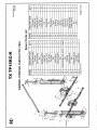
1
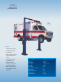
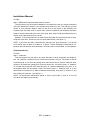
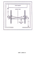
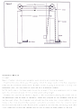
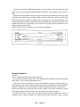
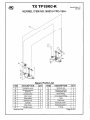
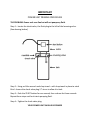
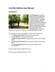
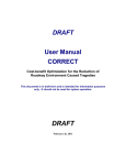
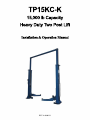
TP15KCK
15,
000l
bCapaci
t
y
HeavyDut
yTwoPostLi
f
t
I
ns
t
a
l
l
a
t
i
o
n& Ope
r
a
t
i
o
nMa
nua
l
REV A-0800113
15,000 LB.
HEAVY DUTY
TWO POST LIFT
TP15KC-K
Heavy Duty
Two Post Lift
Features:
✦
15,000 lb. lifting capacity
✦
Low profile automatic
arm restraints
✦
Dual 3” diameter cylinders
with low friction chain
rollers
✦
“Big Foot” base plates
for stability (2’ x 3’)
✦
Electrical override
automatic safety shut-off
on clear-floor models
✦
FREE mounting hardware
✦
Durable powder-coated
paint finish
SPECIFICATIONS:
TP15KC-K
Capacity
Lifting speed
Power pack
Amperage
Lifting height
Lifting height with adapters
Width overall
Width between posts
Height overall
Shipping weight
15,000 lbs.
45 sec.
2hp 220/230 vac
20 amps
80 1⁄2”
87”
150”
121 1⁄2”
180”
2,474 lbs.
TUXEDO DISTRIBUTORS LIMITED WARRANTY
Structural Warranty:
The following parts and structural components carry a five year warranty:
Columns
Legs
Top Rail Beam
Carriages
Uprights
Arms Swivel Pins
Tracks Overhead Beam Cross Rails
Limited One-Year Warranty:
Tuxedo Distributors, LLC (“Tuxedo”) offers a limited one-year warranty to the original purchaser of
Tuxedo lifts and Wheel Service in the United States and Canada. Tuxedo will replace, without charge, any
part found defective in materials or workmanship under normal use, for a period of one year after purchase.
The purchaser is responsible for all shipping charges. This warranty does not apply to equipment that has
been improperly installed or altered or that has not been operated or maintained according to specifications.
Other Limitations:
This warranty does not cover:
1.
2.
3.
4.
Parts needed for normal maintenance
Wear parts, including but not limited to cables, slider blocks, chains, rubber pads and pulleys
Replacement of lift and tire changer cylinders after the first 30 days. A seal kit and installation
instructions will be sent for repairs thereafter.
On-site labor
Upon receipt, the customer must visually inspect the equipment for any potential freight damage before
signing clear on the shipping receipt. Freight damage is not considered a warranty issue and therefore must
be noted for any potential recovery with the shipping company.
The customer is required to notify Tuxedo of any missing parts within 72 hours. Timely notification must
be received to be covered under warranty.
Tuxedo will replace any defective part under warranty at no charge as soon as such parts become available
from the manufacturer. No guarantee is given as to the immediate availability of replacement parts.
Tuxedo reserves the right to make improvements and/or design changes to its lifts without any obligation
to previously sold, assembled or fabricated equipment.
There is no other express warranty on the Tuxedo lifts and this warranty is exclusive of and in lieu of all
other warranties, expressed or implied, including all warranties of merchantability and fitness for a
particular purpose.
To the fullest extent allowed by law, Tuxedo shall not be liable for loss of use, cost of cover, lost profits,
inconvenience, lost time, commercial loss or other incidental or consequential damages.
This Limited Warranty is granted to the original purchaser only and is not transferable or
assignable.
Some states do not allow exclusion or limitation of consequential damages or how long an
implied warranty lasts, so the above limitations and exclusions may not apply. This warranty
gives you specific legal rights and you may have other rights, which may vary from state to state.
1905 N Main St Suite C, Cleburne, TX 76033
Ph 817-558-9337
Fax 817-558-9740
Installation Manual
TP15KC
Parts Check List
Notes about your TP15KC lift
Installation Instructions
Step 1 Measure lift area and check for defects
Step 2 Cylinder assembly
Step 3 Position columns and uprights, level columns and install top beam
Step 4 Install anchor bolts and re-level columns
Step 5 Install and adjust cables
Step 6 Install power unit, hoses and cut-off cable
Step 7 Install arms
Step 8 Install spinup pads and check height adapters
Step 9 Electrical hook-up
Step 10 Test and adjust lift
Operation
Learn proper operation and recheck lift components
Maintenance Schedule
Please read and follow maintenance guide
Troubleshooting Guide
REV A-0800113
Installation Manual
TP15KC
Parts check list
IN COLUMN2 40’8’’x 3/8’’ cables with four nuts and washers
2 3’’x 36’’pistons with rollers
ON TOP1 Power unit
1 “O” parts box
4 telescoping arms
1 overhead beam
IN PARTS BOX1 71’’hose
1 412’’hose
4 arm pivot pins
4 spinups
20 anchor bolts
1 catalog
1 small parts bag
SMALL PARTS BAG1 1/16’’wire
2 ferrules
1 6’’ pipe for piston
1 st thread T w/ O-ring
2 90 F.M. elbow
4 5/16’’nylock nuts
4 5/16’’18 nuts
4 5/16’’x 1’’hex bolts
15 shims
2 3/4’’plugs
REV A-0800113
Important notes
About your TP15KC lift…
Do not install this lift on any asphalt surface.
Do not install this unit on any surface other than concrete conforming to minimum
specifications.
Do not install this lift over expansion joints or cracks. Check with building architect.
Do not install this lift on a second floor with a basement beneath without written
authorization from building architect.
This lift is only as good as the floor you put it on. A good level floor is recommended for
proper lift operation. Cement should be minimum of 4’’thick and 3,000 psi tensile strength
with steel or fiber mesh reinforcement.
The lift is intended to raise the entire body of the vehicle only. Do not attempt to lift only
part of the vehicle. Improper use of this equipment could result in damage to the lift,
yourself or other property.
The lift is intended to lift vehicles only. It is not designed to lift any person or equipment
containing persons.
All persons using this equipment should be qualified, responsible persons and should
follow the operation and safety guidelines set forth in this manual.
For specifications on concrete pads, please call for technical assistance.
Improper installation can cause damage or injury. Manufacturer will assume no liability for
loss or damage of any kind, expressed or implied, resulting from improper installation or
use of this product. Read the installation and operation manual in its entirety before
attempting to install the lift.
REV A-0800113
Installation Manual
TP15KC
Step 1: Measure lift area and check area for defects
The first step to any successful installation is to measure the bay for correct positioning
of the lift. Measure the width of your doorway and divide it by two. This will give you the
center of your doorway. Make a mark on the floor at the center of the doorway and
measure from the side—wall to center mark. Note the distance and measure the same
distance from the side wall at the front of the shop. Now snap a chalk line between the two
marks—this is the center line for your lift.
Measure 74’’from the center line to each side of the center line at front and rear of shop.
Snap two more lines. These are your lift’s outer dimensions ( see figure 1 ).
NOTE: If you have less than 4’’between the wall and your outer dimension, you should
move the lift over to allow for at least 4’’ of space. Tuxedo Equipment recommends 12’’
between the wall and the outer dimension, but where that is not possible, 4’’is acceptable.
Installation Manual
TP15KC
Step 1: continued
Find the length of the bay minus any work benches or other equipment and divide by
two. For example, a 25’bay minus a 2’work bench equals a 23’ bay. The center of the lift
would be equal, at 11’6’’from the garage door and the work bench. Draw a chalk line. Now
measure 18’’toward the garage door from the center line, this will be point “a”. Measure
18’’ toward the work bench and mark this point “b”. Measure diagonally from point “a” to
the opposite side 152’’and make a mark. This will be point “c”. Measure from “b” in the
same manner to find point “d”. Mark a chalk line horizontally, from point “a” to point “d” and
this will be your base line. ( see figure 2 )
NOTE: You should have 36’’between points “a” and “b” just as with “c” and “d”. If not, find
the center and adjust as necessary.
REV A-0800113
REV A-0800113
Ro
d
You are now ready to install the top beam. Carry the beam to the top and hook each
side to the top of an upright, guiding the bolt into the slot. Hand tighten nuts on the two
bolts.
Check the columns again to see if they are level and on the base line. You many need
to hammer the columns using a rubber mallet, toward or away form center in order to get
them level. Be sure to keep the columns even on the base line. The outer dimensions are
not as important at this point. Check top for space between the upright and top beam. You
should have less than 1/4’’between. If you have more, tighten nuts at top beam on both
side and re-level the columns.
NOTE: Double check everything now—next step is permanent!
Installation Manual
TP15KC
Step 4: Install anchor bolts and re-level columns
You will need a rotary hammer with a 3/4’’carbide Hammer Drill bit ( most rental outlets
carry them ). Do not use a regular drill and bit!
Your floor must be a minimum of 5’’thick and 3000 psi concrete of better. Using your
rotary hammer, drill twenty 3/4’’hole. Drill through the floor and hammer the anchor bolts in
half-way ( install the nut and flat washer on the bolt before placing them into the hole ).
NOTE: Be careful not to move the columns when drilling. One way to avoid this is to drill
the holes and place the bolts one-at-a-time and save the inside hole for last.
Recheck the level of each column and place shims around or beside each bolt and
wherever there is space. Hammer the anchor bolts all the way down. Using a torque
REV A-0800113
wrench, tighten the anchor bolts to 120 pounds of torque. Recheck the level of the
columns. If the columns are off, loosen the anchors and use a pry bar to tilt the columns
and shim as needed. Retighten and check again. Now tighten the bolts on the uprights.
With all bolts tight and the columns as close to level as you can get, you will have a good
solid installation and years of trouble-free service.
Step 5: Install and adjust cables
Using two people, a fork-lift or a shop crane, lift each carriage to the second or third lock.
Allow each carriage to rest on the locks and measure each side to be sure they are at the
same height. Unwrap the two large cables and separate them. Remove the four 3/4’’lock
nuts and four 3/4’’thin flat washers. Place nuts and two flat washers on each carriage so
they are easy to get at.
With your back to the door and standing between the posts, turn to you left. This will be
called the “left” column. The side closest to the front wall will be the front end and the side
closest to the door will be called the back.
Grab one cable end and run it over the left front pulley on the upright, down through the
slot in the upright and through the hole in the corner of the carriage. Drop the end down on
the floor, grab the end and put a flat washer and nut on it. Tighten the nut about 2/3 of the
way on the rod. Grab the other end of the same cable and run it over the top of the front
right pulley, down through the slot and straight down inside the carriage to the floor. Run
the cable under the pulley on the bottom, up through the carriage and into the hole in the
corner of the carriage. Pull the end through the hole. Make sure the other rod is now sitting
in the hole in the other carriage. If your see less than 2’’of rod sticking up, you can install
the flat washer and nut, otherwise go back to the left side and tighten the nut more to take
up the slack. Install the other cable in the same fashion, starting from the right side and
running it over the back pulleys.
With both cables in place, you are ready to adjust. Start on the left side. With a pair of
vice grips, grab the bottom of the rod whose threads are pointing up. Place an 11/16’’deep
socket on the nut and tighten it until the opposite side raises 1/4’’. Tighten the other side
the same way until it comes back down 1/4’’and then give it one full turn. Both cables
should now have the same tension.
NOTE: Do not over tighten cables. This will cause lift to lose carrying capacity and could
damage the components.
Installation Manual
TP15KC
Step 6: Install power unit, hoses and cut-off cable
Unpack the power unit from the box and remove the wood shipping board. Inspect the
unit for damage before continuing. Remove the plastic cap from the 3/8’’port on the side of
the pump and install the “T” fitting found in the parts box. Screw in the “T” until the O-ring
touches the pump and the ends are facing the top of the motor and the bottom of the tank.
Then use an 11/16’’wrench to tighten the locking nut and assure a good seal. Next use a
screwdriver to pry off the 1’’plastic cap from the tank. Place a funnel in the hole and fill the
tank with 3.5 gallons of AW32 hydraulic oil ( NAPA part # 760 is recommended ). Locate
REV A-0800113
REV A-0800113
the four 5/16’’x 1’’bolts, four nuts and four lock nuts in the parts box. Place the four bolts in
the four holes on the mounting plate on the column, then place the four nuts hand-tight
onto the four bolts. Hang the power unit on the four bolts and put the four lock nuts in
place to hold them. Tighten the four nuts first, then the lock nuts.
Unpack the long hose and connect on end to the fitting at the back of the left column.
Run the hose up and over the top along the top along the top beam and down through the
other side to the top of the “T” fitting. You many wish to attach the hose to the top beam
with wire ties or clamps. Attach the shout hose to the bottom of the “T” and then to the
bottom of the right column.
Check all fittings to be sure they are tight, to avoid leaks!
Attach the 1/16’’cable to the flat washer at the top of the left side uptight using the small
aluminum ferrules. Loop the cable through the ferrule, then through the washer and
back through the ferrule. Crimp the ferrule to hold the cable. Pass the cable through
the washer on the right side and down through the empty bolt hole in the middle of the
upright. Loop the cable through the eye on the cut off switch box, secure with ferrule.
Make it as tight as you can without tripping the cutoff switch.
Step 7: Install arms
Place the four arms onto the carriage torsion tubes. Line up the holes and secure with
steel swivel pins.
Step 8: Install spinup pads and check height adapters
Screw the four spinup pads onto the arms and test to see if they screw up and down
smoothly in the arm nut. Slip the four truck adapters over the pads to make sure they all fit.
If you have one that doesn’t fit, call the service line for a replacement.
Step 9: Electrical Hook-up
The electrical hook-up should be done by a certified electrician. The power unit requires
220v 30 amp circuit breaker. It is recommended that you install a means of shutting down
the power in close proximity to the power unit (a twist lock plug hung from the motor will be
sufficient). The motor is factory pre-wired for proper power and rotation.
Installation Manual
TP15KC
Step 10: Test and adjust Lift
With the power properly hooked up and turned on, push the silver button to raise the lift
(the cylinders will take a little while to catch up with the chain, then the lift will begin to rise).
Raise the lift as high as it will go. Pull the key ring located near the bottom of each carriage
to release the safety locks. Locate the lowering handle on the power unit. Pull and hold
handle until the lift goes all the way down to the floor. Continue holding handle for at least
30 seconds to allow any air to escape from the hydraulic system. Once the lift is fully down,
it’s a good idea to have someone push down on the cylinders while you hold out the
lowering handle. This will force out any additional air pockets. You only need do this once.
Run the lift all the way up and down two more times. While running the lift, listen to the
REV A-0800113
safeties clicking. Each side should click within one second of each other or simultaneously.
If they are not clicking together, you can adjust the cables to compensate by either
tightening the side that is clicking first or loosening the side that is clicking last. Remember
not to over-tighten cables—they should be firm, much like a banjo string.
If one or both safeties are not clicking at all, you will need to adjust the safety locks. This
can be done by raising the lift until you see a bolt attached to the safety latch through the
hole in the side of column. You will also see a bolt attached to the safety latch. Give the
bolt one turn clockwise and run the lift up and down once again. Continue this process
until the safety starts to work. If the safeties are locking as you lower the lift, you will need
to turn the bolt counter-clockwise in the same manner.
Installation Manual
TP15KC
Operation: Learn proper operation and recheck lift components
On model TP15KC swing front arms to the front and the rear arms to the rear. Once
arms are in position, pull a car into the bay. A general rule of thumb is to stop the car with
the center of the wheel base even with the center of the columns.
Swing the four arms under the vehicle and position the pads under the appropriate
lifting spots. (If you are not sure of the proper lifting points, you should check the vehicle’s
service manual or contact the vehicle manufacturer.) Adjust the screw pads so they all hit
their lift points at the same time. This will allow the car to be level when rising.
With the pads in their proper locations and no obstructions around the lift or vehicle, you
may now press the button on the power unit to raise the vehicle.
Raise the vehicle so that the tires are only 6’’off the ground. Walk to the back of the
vehicle and push up and down on the bumper. The vehicle will rock, but should not at any
time lose contact with the pads. If the vehicle is bouncing off the pads or feels at all
unstable, you should lower it back to the ground and reposition the pads to balance the
load. Repeat this process until the vehicle is completely stable.
When the vehicle is stable, you many raise the lift all the way to the top. Listen to
safeties and adjust if necessary.
The proper operation of the lift requires that any time you raise a vehicle to work on it,
you must lower the lift into the safety locks. This is done by raising the vehicle to the
desired height and lowering the lift until it stops on the next available lock. To lower vehicle,
you must first raise the lift 1/2’’, release the safeties by pulling the key ring located near
the bottom of each carriage, then pull the lowering handle. If you wish to lower the lift
halfway and resume working on the vehicle, you must lower the vehicle 6’’below the
desired height, raise the lift again to engage the locks and then lower the lift onto the
locks.
Never work under or near the lift without the locks engaged—the pump is not intended
to be a load-holding device. Not using the locks will result in premature failure of the
cylinders, pump and cables—and can cause serious property damage or personal injury.
Failure to heed this warning will result in immediate termination of you warranty.
Installation Manual
REV A-0800113
TP15KC
Maintenance
Maintenance is the key to smooth, safe operation and longer life of your lift. Follow
these guidelines on a regular basis to keep your lift running efficiently.
1. Your lift is only as good as the floor it is mounted on. Cracked or shallow concrete
should be watched at all times. Although your floor may be thick enough according to
manufacturers specs, cracks and shallow spots can cause bolts to loosen and pull out of
the floor. All anchor bolts should be checked and retightened at least once a month. Loose
anchor bolts and weak cement are the number one cause of lift failure!
2. Grease all the corners of the columns where the carriages run up and down. The
grease will do more good if you periodically clean off the old grease to get rid of any grit.
A thin film of grease works better than thick blobs.
3. You should oil the chains on your lift at least twice a year to keep them from rusting
and freezing up. Thirty-weight motor oil or motorcycle chain lube will be sufficient.
4. All of the pulleys on your lift should be sprayed with a light oil such as WD-40 or
similar lubricant, two to three times a year.
5. You should check for cracked or warped parts regularly and re-tighten any loose
bolts.
6. Cables are an important part of your lift. They keep both sides running equal to the
other, allowing the safeties to catch together. If one side of you lift is running ahead of the
other, most likely it is time to adjust your cables. Follow this simple procedure:
a. Raise the lift so the top of the carriage clears the chain and pulley.
b. Notice the threaded rod and nut which stick out though the top of each carriage.
These are your adjusting nuts.
c. You will tighten the nut on the side that is lifting behind the other by holding the
bottom of the threaded rod with a pair of vice-grips and turning the nut with a
suitable wrench or socket.
d. Run the lift up and down and determine if you need further adjustment. If so, repeat
steps a through c.
If at any time you’re not sure of the safe operation of the lift, discontinue using it and call
the technical support line for assistance.
Installation Manual
TP15KC
Troubleshooting Guide
PROBLEM
Motor won’t run
POSSIBLE CAUSE
SOLUTION
1. Fuse or circuit breaker.
1. Replace blown fuse or reset circuit
2. Incorrect voltage to motor.
breaker.
3. Wiring connections.
2. Supply correct voltage to motor.
4. Burned out micro switch.
3. Check and repair or insulate all
5. Burned out motor wingdings.
connections.
REV A-0800113
4. Replace micro switch.
5. Replace motor.
Motor
runs
but
won’t raise lift
1. Motor runs in reverse direction.
1. Change motor rotation by reversing
2. Open lowering valve.
motor.
3 .Pump is sucking air.
2. Repair or replace lowering valve.
4. Suction tube is off of pump.
3. Tighten all suction line fittings.
5. Low oil level.
4. Replace suction tube.
5. Top-off tank.
Motor runs, raise
1. Motor is running on low
1. Supply correct voltage to motor.
lift, but not vehicle
voltage.
2. Clean lowering valve.
2. Debris in lowering valve.
3. Replace Relief Valve cartridge.
3.
Improper
relief
valve
4. Check vehicle weight or balance load
properly.
adjustment.
4. Overloading of lift.
1. Debris in check valve.
1. Clean check valve.
2. Debris in lowering valve.
2. Clean lowering valve.
3. External oil leaks.
3. Check for and repair any leaks.
1. Equalizer cables not properly
1. Adjust cables according to manual.
adjusted.
2. Shim column(not more than 1/2’’) or
2. Lift installed on uneven floor.
adjust spin-up pads to compensate.
Anchor bolts won’t
1.
1. Remove bad cement, pour new pad for
stay tight or are
insufficient.
lift per specs in manual.
pulling out of floor
2. Holes are too big for bolts.
2. Relocate lift using the proper size drill
Lift
settles
down
slowly
Lift
goes
up
unevenly
Cement
thickness/strength
bit, or pour anchoring cement into holes to
secure bolts.
Safety latches don’t
1. Safety not adjusted properly.
1. Raise lift until safety adjusting bolt
work
2. Safety spring not connected.
appears in window, adjust as needed.
3. Flat washer bent too far,
2. Reconnect safety spring.
squeezing release cable.
3. Blend flat washer way from release
4. Safety latch is rusted or frozen.
cable until it moves freely.
4. Spray penetrating oil on latch and work
the latch until it moves freely.
Cylinder whines or
1. Dry or tight seal.
chatters
1. Remove cylinder vent and spray
Dura-lube or Teflon spray lube into
cylinder.
Oil squirts out of
1. Bad seal.
1. Replace seal or cylinder.
cylinder vent
REV A-0800113
REV A-0800113
MAINTENANCE
The following periodic maintenance is the suggested minimum requirements and
minimum intervals: accumulated hours or monthly period, which ever comes first. If
you hear a noise or see any indication of possible failure cease operation immediately
and inspect, correct and/or replace parts as required.
Following these maintenance procedures is the key to prolonging the useful lift of your
lift.
IF AT ANY TIME YOU’RE NOT SURE OF THE SAFE OPERATION OF THE
LIFT, DISCONTINUE USING IT AND CALL YOUR DISTRIBUTOR FOR ASSISTANCE.
WARNING OSHA AND ANSI REQUIRE USERS TO INSPECT LIFTING EQUIPMENT
AT THE START OF EVERY SHIFT. THESE AND OTHER PERIODIC INSPECTIONS
ARE THE PESPONSIBILITY OF THE USER.
DAILY PRE-OPERATION CHECK
The user should at least perform the following checks daily.
Daily check of Safety Latch System is very important — the discovery of device failure
before needed could save you from expensive property damage, lost production time,
serious personal injury and even death.
Check Safety Latches for free movement and full engagement with rack.
Check hydraulic connections, and hoses for leakage.
Check Snap rings all rollers and sheaves.
Check Bolts, Nuts, and Screws and tighten.
Check Wiring and Switches for damage.
Keep base plate free of dirt, grease and any other corrosive substances.
Check for stress cracks in the concrete floor near the anchor bolts which, if present,
could cause the anchor bolts to loosen and pull out of the floor.
Check Cables: Cables keep both sides of the lift running equally allowing the safeties to
catch together. If one side of your lift is running ahead of the other, most likely it is time
to adjust your cables. Follow this simple procedure:
1. Raise the lift so the top of the carriage clears the pulley at the bottom of the post.
2.
Notice the threaded rod and nut that sticks out through the top of each carriage. These
are your adjusting nuts.
3.
Tighten the nut on the side that is lifting behind the other by holding to bottom of the
threaded cable end with vice-grips and turning the nut with a suitable wrench.
4. Run the lift up and down and see if it needs more adjustment. If so, repeat steps 1
through 3.
Check floor for stress cracks near anchor bolts.
REV A-0800113
IMPORTANT
POWER UNIT PRIMING PROCEDURE
THE PROBLEM: Power unit runs fine but will not pump any fluid.
Step 1 – Locate the check valve, the flush plug to the left of the lowering valve.
(See drawing below.)
Step 2 – Using an Allen wrench and shop towel – with shop towel in place to catch
fluid – loosen the check valve plug 2 ½ turns to allow it to leak.
Step 3 – Push the START button for one second, then release for three seconds.
Repeat these steps until unit starts pumping fluid.
Step 4 – Tighten the check valve plug.
YOUR POWER UNIT SHOULD BE PRIMED