1
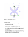
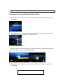
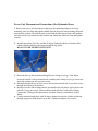
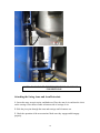
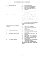
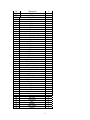
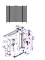
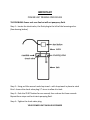
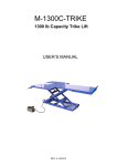
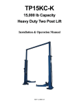
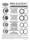
TP12KC-D
12,000 lb Capacity Two
Post Symmetric Lift
PLEASE READ ENTIRE MANUAL BEFORE
INSTALLATION OF THIS LIFT
REV A-071213
12,000 LB.
HEAVY- DUTY
TWO POST LIFT
WITH DIRECT DRIVE
CYLINDERS
TP12KC-D
Heavy-duty
Two Post Lift
with Direct Drive
Cylinders
Features:
SPECIFICATIONS
TP12KC-D
Capacity
Height overall
Width overall
Lifting height
With adapters
Width between columns
Drive through
Arm extension
Power pack
Shipping weight
12,000 lbs.
165”
151 1⁄8”
5 1⁄2” - 72”
79 5⁄8”
122”
109”
37 1⁄2” - 57”
2hp 220 vac
2,235 lbs.
✦
12,000 lb. lifting capacity
✦
Direct drive high pressure
cylinders
✦
Extra long (48”) carriage
for less wear on sliders
✦
Padded overhead
cut-off bar
✦
Single point pneumatic
lock release
✦
Drop in adapters are
standard
✦
Powder-coated
paint finish
TUXEDO DISTRIBUTORS LIMITED WARRANTY
Structural Warranty:
The following parts and structural components carry a five year warranty:
Columns
Legs
Top Rail Beam
Carriages
Uprights
Arms Swivel Pins
Tracks Overhead Beam Cross Rails
Limited One-Year Warranty:
Tuxedo Distributors, LLC (“Tuxedo”) offers a limited one-year warranty to the original purchaser of
Tuxedo lifts and Wheel Service in the United States and Canada. Tuxedo will replace, without charge, any
part found defective in materials or workmanship under normal use, for a period of one year after purchase.
The purchaser is responsible for all shipping charges. This warranty does not apply to equipment that has
been improperly installed or altered or that has not been operated or maintained according to specifications.
Other Limitations:
This warranty does not cover:
1.
2.
3.
4.
Parts needed for normal maintenance
Wear parts, including but not limited to cables, slider blocks, chains, rubber pads and pulleys
Replacement of lift and tire changer cylinders after the first 30 days. A seal kit and installation
instructions will be sent for repairs thereafter.
On-site labor
Upon receipt, the customer must visually inspect the equipment for any potential freight damage before
signing clear on the shipping receipt. Freight damage is not considered a warranty issue and therefore must
be noted for any potential recovery with the shipping company.
The customer is required to notify Tuxedo of any missing parts within 72 hours. Timely notification must
be received to be covered under warranty.
Tuxedo will replace any defective part under warranty at no charge as soon as such parts become available
from the manufacturer. No guarantee is given as to the immediate availability of replacement parts.
Tuxedo reserves the right to make improvements and/or design changes to its lifts without any obligation
to previously sold, assembled or fabricated equipment.
There is no other express warranty on the Tuxedo lifts and this warranty is exclusive of and in lieu of all
other warranties, expressed or implied, including all warranties of merchantability and fitness for a
particular purpose.
To the fullest extent allowed by law, Tuxedo shall not be liable for loss of use, cost of cover, lost profits,
inconvenience, lost time, commercial loss or other incidental or consequential damages.
This Limited Warranty is granted to the original purchaser only and is not transferable or
assignable.
Some states do not allow exclusion or limitation of consequential damages or how long an
implied warranty lasts, so the above limitations and exclusions may not apply. This warranty
gives you specific legal rights and you may have other rights, which may vary from state to state.
1905 N Main St Suite C, Cleburne, TX 76033
Ph 817-558-9337
Fax 817-558-9740
Model Number
TP12KC-D
Capacity
12,000 lbs.
Lifting height
5.5" - 72"
with adapters
79.625"
Height overall
165"
Width between columns
122"
Drive through
109"
Width overall
151.125"
Arm extension
37.5" - 57"
Power pack
2hp 220vac
Shipping weight
2235 lbs.
2
INSTALLATION INSTRUCTIONS
Choosing A Location
• Use architects' plans when available. See Floor Layout on Page 6 for typical layout
of the12000# inverted cylinder model.
• Two Post Lifts require a minimum ceiling height of 3” higher than the overall height
of the lift being installed. For the TP12KC-D this will be 168” (14').
• The Steel Reinforced Concrete floor must be level, have a minimum thickness of 4
inches, and retain a commercial rating of 3500 psi. The concrete must be cured for a
minimum of 28 days.
• Before making a Final Decision, consider the amount of workday traffic flowing in
and around the location you have chosen. Also consider the amount of room out front
of the lift for a workbench or diagnostic equipment. There may also be some future
building plans to consider. Are you satisfied with your selection?
3
Important General Information
1. There are numerous blends and mixes and additives these days for concrete. All of
these work well when used in the proper application. However, years of experience have
shown that nothing beats a properly cured, steel reinforced concrete slab for this
application. Another thing to watch is additives that claim to harden the concrete faster or
reduce the cure time. Again, these things have their place, but not in this application! A
steel rod or mesh reinforced slab cured 28-30 days with the slab kept properly hydrated
gives the best results.
2. Checking bolts for tightness to some people means that once a week they grab a
wrench and go around yanking a quarter of a turn on every nut and bolt they see. This is,
of course, not the proper way of handling any bolt, especially the stress anchor used to
anchor your lift. When the anchors are installed, they must be torqued with a torque
wrench to 150 foot-pounds initially. After a period of time, they will loosen up some.
This is normal. When checking the anchors just put a wrench on them and “feel of them”
or apply a small amount of torque to the bolt. If it is tight, it is good to go. If it is loose,
get a torque wrench and tighten it to 60-90 foot-pounds.
3. The lift is not designed for an outdoor installation because of the possible damage and
degradation to the hydraulics and the electrical components caused by direct exposure to
the elements. If the unit is installed in a building or outbuilding with a floor that is
anything other than the recommended concrete floor, a pad can be poured. The size and
construction of the pad can vary depending on the soil conditions and the local weather
conditions. It is recommended that each of these situations be handled separately by a
local engineer.
4. Never place a lift in a pit or depression in a garage area or any environment where
gasoline is around. Gasoline fumes tend to gather at the floor and low areas, so the lift
must be mounted on the main floor of the building and not in the basement or a pit.
5. Always remember that your lift is rated at 12000 pounds. This means that the lift will
safely and reliably lift a load of 12000 pounds as long as that load is evenly distributed on
all four arms. If the load is offset or unevenly distributed, then one post can actually be
operating at a load greater than 12000# and the lift can be overloaded with less than the
rated load. So the lift load rating is 12000 pounds or 3000 pounds per arm.
Positioning the Post (Columns)
4
Carefully examine the packed unit for damage before unpacking. Any claims for damage
should be filed with the freight carrier at delivery. Unbolt the package being careful to
save the bolts and use them to reinstall the top caps after unpacking the lift. Place posts in
bay using dimensions shown in Floor Layout (Figure 1). The bases must be square with
the layout lines as shown. It is recommended that the extensions be mounted to the posts
before standing them up. You will need a considerable amount of help standing up these
posts.
Drilling and Anchoring
A. Drill 3/4” x 5-1/2” (minimum depth) holes in the concrete floor using the holes in the
base plates as guides. Drill the holes perpendicular to the surface, being sure not to
enlarge them by allowing the drill to wobble. Do not ream-out the holes. (See Anchoring
Instructions, Figure 2). Be careful when drilling the holes, the posts can tip over.
B. Blow all of the dust and debris from the holes, then clean around the openings with
a wire brush. A clean hole will improve the prospect of solid anchoring.
c. It is recommended that the lift to be located 10’ – 12’ from the nearest obstruction
in front of the lift and 2’ – 3’ from the nearest obstruction on the sides of the lift.
2. To install Anchor:
A. Assemble the washer and nut onto the anchor bolt with nut just below impact section
of bolt.
B. With a hammer, carefully tap the anchor bolt into the concrete until the washer is
resting on the base of the column. DO NOT DAMAGE THE NUT OR THREADS!
C. Before tightening the nuts, level and plumb the columns, using the shims provided.
Note: If more than 1/2” of shims is required to level the post, Do Not Use the
Anchors supplied with this lift. It will be necessary to purchase longer anchors
for your application. The brand of anchor recommended is the Hilti Kwik-Bolt.
D. When columns are level and plumb, tighten the nuts with a Torque Wrench to 150 ftlb. If anchors do not tighten to 150 ft-lbs in existing floor, replace concrete under
each post with a 6’ x 6’ x 10” thick pad keyed into and flush with the existing floor.
Concrete must be 3500 PSI minimum.
5
NOTE: NEVER USE AN IMPACT WRENCH TO TIGHTEN ANCHOR BOLTS!
Attaching The Overhead Beam and Shut-Off Bar
1. The overhead beam is attached to the extensions at the ends with eight nuts and bolts.
See picture.
2. The cable sheaves must assembled onto the shafts with the spacers supplied as shown
in the picture prior to attaching the overhead channel.
3.To Install the Shut-Off Bar
Attach the shutoff bar and switch housing to the underside of the overhead beam. Attach
single bolt and bar first, then install switch housing.
4. Run electrical cord into the beam and back out of the column using provided bulk
head fittings.
6
Attaching the Air Actuator
1. Locate offside air cylinder and insert 6mm hose into PTC fitting.
2.Run air hose up and over top of column, running through top side of overhead beam
and down to main side lock assembly.
3.Connect air hose to provided PTC 3-way fitting, cut to size a piece of air hose and run
to main side air cylinder PTC fitting. Remaining hose will be connected from 3-way
fitting to palm actuated air release button valve.
4.Attach palm valve to steel bracket on side of column.
5.Connect shop air to palm valve. We recommend using leftover hose and NPT fitting
(not included).
Installing the Equalizer Cables
A. Manually lift both carriages to about waist height. Be sure they are the same height
and on the same latch location on the carriage.
7
B. Install the Equalizer Cables using the Routing for the lift as shown in the picture. The
cables should be taught, but no too tight. Be certain to tighten the jam nuts.
Cables are routed identically the same on both columns. Cable on right is routed down
and around the sheave then up and over the overhead beam. Then routed down to the top
of the carriage.
Be sure cables are seated securely on the sheaves.
8
Power Unit Placement and Connection of the Hydraulic Hoses
1. Remove the power unit from the box and locate the mounting hardware. For easy
mounting, place two bolts through the middle slots on the power unit mounting plate and
start the nuts on them. Then lift the unit up and slide the unit into position while guiding
the bolts into the slots on the bracket from the top. Install the other two bolts and tighten
securely.
2. Install longest hose first. One end has 90 degree fitting that hooks to bottom of the
offside cylinder and then route hose through the leg gusset.
DO NOT OVER TIGHTEN FITTINGS!!.
3. Route the hose up the column installing the hose clamps as you go. Then follow
across the outside of the overhead beam (installing hose clamps as you go). Down the
main side column towards your power unit.
4. Run hose through the top of your power unit bracket until the end of your hose comes
through the bottom of the bracket.
5. Install power unit elbow fitting into the port that has the red plastic cap located on the
left side of your power unit. Connect shortest hydraulic hose to the elbow fitting.
Connect the T fitting to the shortest hose and then connect overhead hose to the T
fitting.
6. Connect medium length hose with 90 degree fitting to main side cylinder and thread
through leg gussets. Run the hose up to the T fitting and tighten. See pictures –
9
NOTE: DO NOT OVER-TIGHTEN THE HYDRAULIC HOSE
CONNECTIONS!
Attaching the Swing Arms and Arm Restraints
1. Locate the arms, arm pivot pins, and hardware. Place the arm clevis end into the clevis
on the carriage. Place thrust washer on bottom side of carriage clevis.
2. Slide the pivot pins through the arms and carriage until it bottoms out.
3. Check the operation of the arm restraints. Make sure they engage and disengage
properly.
10
Electrical Connection
NOTE: WE STRONGLY RECOMMEND THAT YOU USE A
LICENSED, PROFESSIONAL ELECTRICIAN TO INSTALL
THE POWER TO YOUR TWO POST LIFT!
Filling the Hydraulic Fluid Tank
Remove the vent-cap from the top of the Hydraulic Fluid Tank attached to the Power
Unit. Using a funnel, carefully pour in the Hydraulic Fluid (approximately 12 quarts)
until fluid gets near the top of the tank. Replace the vent-cap.
***********************************************
We Recommend Using One of the Following Fluids:
Dextron III Non-Detergent
AW #32 Hydraulic Oil
***********************************************
11
Bleeding the System
1. Actuate the power unit and hold the button until both carriages lift off the locks.
2. Carefully loosen the bleeding screw at top end of the cylinder and allow the trapped
air to escape. CAUTION! The air in the cylinders is under pressure. Protect your
eyes and cover the end of the cylinder with a rag because oil may spray out of the
cylinder.
3. Repeat the process for the other cylinder.
CAUTION: DO NOT OVER TIGHTEN THE BLEED PLUG
Adjusting the Equalizer Cables to Synchronize Carriages
Raise and lower the lift several times while listening to the clicking of the safety locks
in each column. If the safety locks are not clicking in unison (at the same time),
determine which carriage is running behind, and tighten (just a few turns) the
adjustment bolt on the opposite side. When the cables are properly adjusted, they
should feel fairly tight.
Final Assembly
1. Using the adhesive cable anchors and cable ties, fasten the overhead switch cord and
the air lines to the posts.
2. Install lock release covers over both assemblies with provided screws.
3. Check all nuts and bolts, making sure they are tight. Check the jam nuts on the
equalizer cables for tightness.
4. Check all of the hydraulic fittings for possible leaks. Check all the fittings for
proper tightness.
5. Make sure the Carriages are synchronized.
6. Make sure post are greased.
7. Place a vehicle on the lift (see operating section for instructions below for to the safe
and proper way to lift a vehicle), raising the vehicle until it clears the floor. Lower the
lift all the way to the floor and recheck all the anchor bolts. Raise the vehicle all the
way to the top and lower all the way to the floor several times. This procedure will
ready the lift for continued operation.
OPERATION
1.
Center the vehicle left and right between the posts.
12
2.
Position the swivel pads under the frame of the car at the proper lifting points.
(To find the proper lifting points, consult the vehicle’s service manual or other
approved publication.)
3.
Push the up button and raise the lift until the swivel pads make contact with lifting
points.
4.
Check all swivel pads to make certain all adapters are making full and proper
contact. NEVER go under a vehicle unless all adapters are in secure contact with
the vehicle.
5.
Raise the vehicle approximately 2 feet and check the stability by rocking the
vehicle. Make sure vehicle weight is centered. Do not raise if weight is front or
tail heavy.
6.
Raise the vehicle to the desired height and lower on the carriage latches. NEVER
go under a vehicle unless the carriage latches are engaged. If any heavy parts are
to be removed, use a set of high stands for added safety.
7.
Before lowering, check the area under the vehicle to be sure it is clear. Raise lift
slightly, pull the Latch Release Handle and hold, then pull down on the lowering
release arm and lower SLOWLY. Keep feet clear.
8.
After lowering, rotate the swing arms back out of the way.
MAINTENANCE SCHEDULE
DAILY
1. Always keep bolts tight.
2. Check for oil leaks.
MONTHLY:
1. Re-torque the anchor bolts if necessary. (See CAUTION! below)
2. Lubricate chains/cables with spray lubricant.
3. Check all connectors, bolts and pins to insure proper mounting.
4. Make a visual inspection of all hydraulic hoses and lines for possible wear or
interference.
!
13
ALL ANCHOR BOLTS SHOULD ALWAYS BE TIGHT. Check the bolts periodically
and tighten if necessary to 60-90 ft.-lbs. after the bolts have been set at installation. If any
of the bolts do not function for any reason, the lift should be shut down until the bolt has
been replaced.
EVERY SIX (6) MONTHS:
1. Make a visual inspection of all moving parts for possible wear, interference or damage.
2. Check all pulleys for proper lubrication. If pulleys seem to be dragging during lifting
or lowering, lightly oil the axle.
3. Check and adjust as necessary, equalize tension to insure level lifting.
4. Check columns for plumbness.
5. Check fluid level of power unit.
6. Lube columns.
14
TROUBLESHOOTING THE LIFT
1.
Motor does not run:
2. Motor runs but lift will not raise:
3.Motor runs but lift picks up partial
load only:
4.
Oil blows out of breather:
5.
Motor hums and will not run:
6.
Lift jerks up and down:
A.
B.
C.
D.
Breaker or fuse blown.
Motor thermal overload tripped.
Defective UP switch. Replace.
Faulty wiring connections. Call
electrician.
E.
Check the overhead shut-off bar
operation.
It could be faulty or stuck-thus
holding the switch open.
A.
Trash is under check valve. Push
handle down and push the UP button at the
same time. Hold for 15 seconds. This should
flush the system.
B.
Remove the check valve cover with
an Allen wrench. Clean the ball and seat and
replace the cover.
C.
Oil level low. Oil level should be just
under the vent cap port when the lift is
down.
A.
B.
Faulty relief valve. Replace.
Oil is coming out of breather on
cylinder.
C.
Seals damaged.
A.
Oil reservoir overfilled.
B.
Lift lowered too quickly while under
a heavy load.
A.
Impeller fan cover is dented in. Take
straighten.
B.
Faulty wiring - Call an Electrician.
C.
Bad capacitor - Call an Electrician.
D.
Low voltage - Call an Electrician.
E.
Lift over loaded.
A.
Cables are too loose - (See Adjusting
The Equalizer Cables).
B.
Air in system - bleed the system.
(See Installation Instructions - Bleeding the
System
15
ITEM
DESCRIPTION
QTY
1
2
3
4
5
6
7
8
9
10
11
13
14
15
16
17
18
19
20
21
22
23
24
25
26
26-1
*26-2
26-3
26-4
*26-5
26-6
26-7
*26-8
*26-9
*26-10
63
64
65
66
67
68
69
70
71
72
73
*74
Column jointings
Adjust washer
Upset bolt
Spindle
Spindle
Baffle ring
Pin
Spring
Safety ass'y
Cam
Pin
Elbow fitting joint
Pin
Pin
Fitting joint
Cylinder
Cross beam parts
Bolt
Washer
Pole
Nut
Sponge bush
Rubber block
Carriage
Hydraulic cylinder
Cylinder barrel
Dust ring
Guide ring
Fixed part for piston
O-ring
Piston rod
Limit ring
Guide ring
O-ring
Packing ring
Pin
Gear
Pin
Gear
Rack spindle
Spring
Key ring
Fitting joint
Nut
Washer
Steel cable
O-Ring
1
12
12
4
4
6
2
2
2
2
2
2
4
2
2
2
1
5
9
1
5
1
16
2
2
2
2
2
2
4
2
2
2
2
2
4
4
8
4
4
4
4
2
8
4
2
1
16
75
76
77
28
29
30
31
32
33
34
35
36
37
38
39
40
41
42
43
44
45
46
47
48
49
50
51
52
53
54
55
56
57
58
59
60
61
63
64
65
66
67
68
69
70
71
72
73
*74
T fitting joint
Fitting joint
Plug
Flat washer
Nut
Link plank
Cap
Bush
Bush
Wheel
Spindle
Vice column jointings
Hoop
Screw
Screw
Plate
Switch cover
Switch
Cable
Oil hose
Oil hose
T fitting joint
Oil hose
Flat washer
Cover
Elbow fitting joint
Switch
Power unit
Column jointings
Air hose
Air hose
Air hose
T fitting joint
Screw
Rubber washer
Salver jointing
Flex arm
Pin
Gear
Pin
Gear
Rack spindle
Spring
Key ring
Fitting joint
Nut
Washer
Steel cable
O-Ring
1
1
1
104
48
4
2
4
2
6
2
2
16
16
16
1
1
1
1
1
1
1
1
8
2
2
1
1
1
1
1
1
1
12
4
4
4
4
4
8
4
4
4
4
2
8
4
2
1
17
75
76
77
64
65
66
67
68
69
70
71
72
73
*74
75
76
T fitting joint
Fitting joint
Plug
Gear
Pin
Gear
Rack spindle
Spring
Key ring
Fitting joint
Nut
Washer
Steel cable
O-Ring
T fitting joint
Fitting joint
1
1
1
4
8
4
4
4
4
2
8
4
2
1
1
1
78
Washer
4
32
33
34
35
36
28
27
29
31
37
A
38
A
31
30
39
40
42
29
28
27
22
41
43
21
18
23
20
25
19
22
26
24
49
39
48
45
44
46
47
2 6 -1
17
20
B
16
70
14
15
B
78
47
51
C
44
71
69
72
53
54
55
68
9
8
7
73
67
6
34
57
58
6
5
56
C
59
60
66
4
65
3
61
63
1
2
77
74
62
58
27
28
18
64
19
50
52
13
14
11
10
2 6 -1 1
2 6 -1 0
2 6 -9
2 6 -8
2 6 -5
2 6 -7
2 6 -6
75
76
2 6 -5
2 6 -4
2 6 -3
2 6 -2
IMPORTANT
POWER UNIT PRIMING PROCEDURE
THE PROBLEM: Power unit runs fine but will not pump any fluid.
Step 1 – Locate the check valve, the flush plug to the left of the lowering valve.
(See drawing below.)
Step 2 – Using an Allen wrench and shop towel – with shop towel in place to catch
fluid – loosen the check valve plug 2 ½ turns to allow it to leak.
Step 3 – Push the START button for one second, then release for three seconds.
Repeat these steps until unit starts pumping fluid.
Step 4 – Tighten the check valve plug.
YOUR POWER UNIT SHOULD BE PRIMED