1
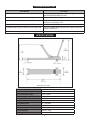
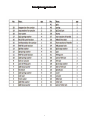
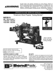
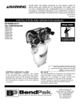
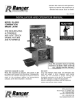
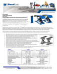
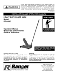
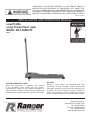
PLEASE READ THE ENTIRE CONTENTS OF THIS MANUAL PRIOR TO INSTALLATION AND OPERATION. BY PROCEEDING YOU AGREE THAT YOU FULLY UNDERSTAND AND COMPREHEND THE FULL CONTENTS OF THIS MANUAL. FORWARD THIS MANUAL TO ALL OPERATORS. FAILURE TO OPERATE THIS EQUIPMENT AS DIRECTED MAY CAUSE INJURY OR DEATH. REV B 02-05-15 INSTALLATION AND OPERATION MANUAL Low Profile Long Frame Floor Jack Model: RFJ-3000LPF REV B SHIPPING DAMAGE CLAIMS When this equipment is shipped, title passes to the purchaser upon receipt from the carrier. Consequently, claims for the material damaged in shipment must be made by the purchaser against the transportation company at the time shipment is received. BE SAFE Ranger™ Floor Jacks are designed and built with safety in mind. However, proper training and thoughtful operation on the part of the operator can increase your overall safety. DO NOT operate or repair this equipment without reading this manual and the important safety instructions shown inside. 1645 Lemonwood Dr. Santa Paula, CA. 93060, USA Tel: 1-805-933-9970 Toll Free: 1-800-253-2363 Fax: 1-805-933-9160 www.rangerproducts.com WARRANTY POLICY A trucking company’s procedure for handling damage is as follows: Ranger Products™ are backed by over 35 years of manufacturing experience. Every Floor Jack bearing the Ranger™ name is sold with the following warranty. 1. 2. 3. 4. wEach Ranger Product™ is warranted to be free from defects in workmanship and material for a period of one year from the date of shipment provided that a written claim for such defect is made within that time. Immediately send out an inspector. An inspection report is filled out on the spot, a copy of which is given to the customer. The customer has to call the carrier to request a claim form. The customer mails in the claim form. The claim usually takes two (2) months to process. If a unit is seriously damaged, your Ranger Products dealer may be able to intervene, requesting that the damaged unit be returned and a new unit delivered. wThis warranty does not cover damage or defects caused by carelessness of the operator, misuse, abuse or abnormal use which in any way impairs the proper functioning of the equipment or by the use or addition of parts not manufactured by Ranger Products™ or its suppliers. THIS WARRANTY IS EXPRESSLY MADE IN LIEU OF ANY AND ALL OTHER WARRANTIES EXPRESSED OR IMPLIED INCLUDING THE WARRANTIES OF MERCHANTABILITY AND FITNESS FOR A PARTICULAR PURPOSE. IMPORTANT SAFETY TIPS ALWAYS MAINTAIN A CLEAN WORK AREA. KEEP VISITORS AND ESPECIALLY CHILDREN AWAY FROM WORK AREA. If your Ranger Products™ machine is not functioning properly, call your Ranger Products™ dealer immediately. On some occasions, an independent contractor may be hired to do the repairs. Within the warranty period, a customer should not hire his own contractor unless it is authorized in writing by Ranger Products™. THIS FLOOR JACK IS TO BE OPERATED BY PROPERLY TRAINED PERSONNEL ONLY. OPERATION BY UNTRAINED PERSONNEL MAY RESULT IN INJURY AND /OR PROPERTY DAMAGE. If it is necessary to return equipment for repairs, your dealer will so advise you. When returning equipment for repairs, see that machines are properly crated and protected, and prepay transportation. For Parts Or Service Contact: Defective parts replaced at no charge must be returned to your dealer or Ranger Products™ within 60 days of the date that the replacement parts are shipped; otherwise, you must pay for the replacement parts at the current selling price. BendPak Inc. / Ranger Products 1645 Lemonwood Dr. Santa Paula, CA. 93060 Tel: 1-805-933-9970 Toll Free: 1-800-253-2363 Fax: 1-805-933-9160 www.bendpak.com www.rangerproducts.com SHIPPING DAMAGE If any damage is found, notify your carrier immediately and save all packaging materials for the carrier’s inspector to examine. Failure to promptly report damage could result in denial of your claim. IMPORTANT NOTE Although every effort has been taken to ensure the accuracy of this document, some information may contain technical inaccuracies or typographical errors. BendPak/Ranger assumes no responsibility or liability for damages incurred directly or indirectly as a result of any errors, omissions or discrepancies. Information and specifications subject to change without notice. 2 THIS OPERATING MANUAL CONTAINS IMPORTANT DETAILS CONCERNING THE SAFE OPERATION OF THIS TOOL. THE USER MUST READ AND UNDERSTAND THESE DETAILS BEFORE ANY USE OF THE TOOL. THIS MANUAL MUST BE RETAINED FOR FUTURE REFERENCE. ALTERATIONS Because of potential hazards associated with this type of equipment, no alterations shall be made to the product. FOR YOUR SAFETY AND TO PREVENT INJURY: Use Service Jack for lifting purposes ONLY. Always support vehicle with jack stands. OWNER/OPERATOR RESPONSIBILITY: The owner and/or operator shall study the product instructions and retain them for future reference. The owner and/or operator shall have an understanding of the product operating instructions and warnings before operating the jack. THIS IS A LIFTING DEVICE ONLY. DO NOT MOVE OR DOLLY THE VEHICLE WHILE ON THE JACK. IMMEDIATELY AFTER LIFTING, SUPPORT THE VEHICLE WITH APPROPRIATE MEANS. Warning information shall be emphasized and understood. If the operator is not fluent in English, the product instructions and warnings shall be read to and discussed with the operator in the operator’s native language by the purchaser/ owner or his designee, making sure that the operator comprehends its contents. DO NOT EXCEED RATED CAPACITY. OVERLOADING CAN CAUSE DAMAGE TO OR FAILURE OF THE JACK. LIFT ONLY ON AREAS OF THE VEHICLE AS SPECIFIED BY THE VEHICLE MANUFACTURER. KEEP HANDS AND BODY CLEAR OF ALL PINCH POINTS. INSPECTION CENTER LOAD ON SADDLE PRIOR TO LIFTING. OFF-CENTER LOADS MAY CAUSE DAMAGE TO JACK, LOSS OF LOAD, PROPERTY DAMAGE, PERSONAL OR FATAL INJURY. Visual inspection should be made before each use of the jack. This inspection should check for abnormal conditions such as cracked welds, leaks, and damaged, loose or missing parts. THIS JACK IS DESIGNED FOR USE ONLY ON HARD LEVEL SURFACES CAPABLE OF SUSTAINING THE LOAD. USE ON OTHER THAN HARD LEVEL SURFACES CAN RESULT IN JACK INSTABILITY AND POSSIBLE LOSS OF LOAD. Any jack that appears to be damaged in any way, is found to be worn or operated abnormally, must be removed from service immediately. Any jack that operates abnormally shall be removed from service until repaired by a qualified repair service center. NO ALTERATIONS TO THE JACK SHALL BE MADE. If the jack is accidentally subjected to an abnormal load or shock, it must be taken out of service immediately and be inspected by a qualified repair or service center. READ, STUDY AND UNDERSTAND THE OPERATING MANUAL PACKED WITH THIS JACK BEFORE OPERATING. It is recommended that an annual inspection is performed on the jack and that any damaged or worn parts, decals or warning labels be replaced with manufacturer’s specified parts. FAILURE TO HEED THESE WARNINGS MAY RESULT IN LOSS OF LOAD, DAMAGE TO JACK, AND/OR FAILURE RESULTING IN PROPERTY DAMAGE, PERSONAL OR FATAL INJURY. 3 ASSEMBLY INSTRUCTIONS Lower the load to rest on the jack stands. Then, make sure that the release valve on the jack is closed tightly (twist the Handle clockwise). 1. Assemble Upper and Lower Handle, insert into Handle Socket and tighten Bolt. 2. To lower load: Re-check to make sure release valve is tightly closed (twist the Handle clockwise). Then, operate the jack handle until the load is raised enough to remove the jack stands. OPERATING INSTRUCTIONS BEFORE USE: Air may become trapped in the hydraulic system during transit. To purge air: 1. Open release valve by twisting Handle counter clockwise. DO NOT CRAWL UNDER VEHICLE WHILE LIFTING VEHICLE OR REMOVING THE JACK STANDS! 2. Pump Handle rapidly 4-6 full strokes. This will expel air that may have entered oil passages during transit. Once jack stands are removed, open release valve very slowly to lower the vehicle (twist the Handle counter clockwise). Lower jack completely so that the vehicle is securely resting on the ground and that jack no longer makes contact with vehicle. 3. Close release valve by twisting Handle clockwise and pump handle. 4. If lift arm is raised, jack is ready for use. If not, repeat this procedure. BEFORE ATTEMPTING TO RAISE ANY VEHICLE, CHECK VEHICLE SERVICE MANUAL FOR RECOMMENDED LIFTING POINTS. Keep hands or feet away from the hinge mechanism of the jack. OPERATION: MAINTENANCE When adding or replacing hydraulic fluid, always use a quality hydraulic fluid. DO NOT use brake fluid, alcohol, detergent motor oil, dirty oil or any fluid other than quality hydraulic fluid. Improper fluids can cause internal damage to the jack and improper or unsafe operation. 1. To Raise Load: Close release valve tightly (by twisting Handle clockwise. DO NOT OVERTIGHTEN. Position jack under load so that saddle will contact load firmly and load is centered so it cannot slip. Operate jack handle until saddle approaches the load. Once again, check to see that saddle is correctly positioned. Raise load to desired height. Place jack stands of appropriate capacity under the vehicle. ADDING HYDRAULIC FLUID With the saddle fully lowered and the jack on level ground, remove the filler screw. Hydraulic fluid should be filled to the level of the filler screw hole. If the level is below this hole, add hydraulic fluid as needed. LUBRICATION All moving joints require lubrication often. Lightly grease saddle post and saddle bottom. Remove handle and grease the lower end of handle where it rotates in the handle socket. Using a grease gun, grease the lift arm pivot shaft grease fitting until grease appears at the end of the shaft. Oil all lift arm linkages, front wheels and rear casters. DO NOT CRAWL UNDER VEHICLE WHILE LIFTING VEHICLE OR PLACING OR REMOVING JACK STANDS! Place jack stands at vehicle manufacturer’s recommended lift areas that provide stable support for the raised Vehicle. Once jack stands are positioned, open the release valve VERY SLOWLY (by twisting the Handle counter clockwise.) 4 TROUBLESHOOTING PROBLEM ACTION 1. Unit will not lift load Purge air from hydraulic system by following procedure under OPERATING INSTRUCTIONS. 2. Unit will not sustain load or feels “spongy” under load. Purge air from hydraulic system as above. 3. Unit will not lift to full height. Purge air from hydraulic system as above. Check to be sure oil level is not too high or low. 4. Unit will not lower completely. Check oil level. Make sure not overfilled. 5. Handle tends to raise up while the unit is under load. Pump the handle rapidly several times to push oil past ball valves in power unit. 6. Unit still does not operate. Contact Parts & Warranty Department. SPECIFICATIONS Maximum Capacity 3,000 lbs / 1,361 kg. Maximum Saddle Height 24” / 610mm Minimum Saddle Height 2.75” / 70mm Frame Height 6.5” /165mm Real Wheel Diameter 2.25 / 57mm Front Wheel Diameter 2.5” 63.5mm Front Wheel Base 11” / 279.4mm Rear Wheel Base 14.5”/ 368mm Chassis Length 34” / 864mm Shipping Weight 112 lbs. / 51kg Shipping Dimensions 39” x 17”x 8” / 980mm x 425mm x 195mm 5 PARTS BREAKDOWN 6 PARTS BREAKDOWN 7 8