1
HDKAJ, HDKAK, HDKAT, HDKAU
Printed in U.S.A.
981-0623B
08-05
Redistribution or publication of this document,
by any means, is strictly prohibited.
Supplement 981-1053
Date: 08-05
Insert with: Operator’s Manual 981-0161 (8-99)
Installation Manual 981-0623 (8-99)
This Supplement adds Model HDKAU to the generator set models covered by the operator’s and installation
manuals in which it is inserted. Page 2 of this Supplement is an updated Specifications page which includes
the new generator set model.
Write a note in the manual under the heading, ABOUT THIS MANUAL, and also on the Specifications page, to
refer to the Supplement for Specifications on Model HDKAU.
Page 1 of 1
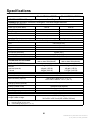
Specifications
Model HDKAJ / HDKAT
Model HDKAK / HDKAU
GENSET CONTROLLER: Integrated Microprocessor Based Engine and Generator Controller
GENERATOR: Brushless, Exciterless, Bearingless, Permanent Magnet Alternator
AC OUTPUT RATINGS:
Power (@1.0 power factor)
Voltage
Frequency
Number of Phases
Current
Line Circuit Breaker(s)
7500 W
120 volts
60 Hz
1
62.5 ampere
One 2-pole, 30 or 35 amp
8000 W
120 volts
60 Hz
1
66.7 ampere
One 2-pole, 30 or 35 amp
ENGINE: 3-Cylinder In-Line, Water-Cooled, Indirect-Injection, 4-Stroke Cycle Diesel
Bore
Stroke
Displacement
Compression Ratio
Oil Capacity (with filter)*
Cooling System Capacity**
Intake and Exhaust Valve Lash (Cold)
OPERATING SPEED RANGE:
2.64 inch (67 mm)
2.68 inch (68 mm)
44 inch3 (719 cc)
23 : 1
3 quart (2.6 l)
4.2 quart (4 l)
0.0065 inch (0.165 mm)
1600 to 3200 RPM (HDKAJ)
2300 to 3200 RPM (HDKAT)
1600 to 3300 RPM
.13 gph (.49 l/h)
.49 gph (1.85 l/h)
.96 gph (3.63 l/h)
.13 gph (.49 l/h)
.49 gph (1.85 l/h)
1.02 gph (3.86 l/h)
FUEL CONSUMPTION:
No-load
Half-load (4000 W)
Full-load
DC SYSTEM:
Nominal Battery Voltage
Minimum Battery Capacity
Maximum Regulated-Voltage Battery
Charging Current (Optional)
Fuse F1 (control circuit)
Fuse F2 (starter solenoid circuit)
Fuse F3 (glow plug circuit)
12 volts
450 CCA*** down to 0° F (–17° C)
650 CCA*** down to –20° F (–29° C)
10 ampere
10 ampere mini-bayonet
10 ampere mini-bayonet
25 ampere
WEIGHT AND SIZE:
Weight (wet)
Length x Width x Height
*
**
***
See oil filling instructions.
Includes coolant recovery tank.
Cold Cranking Amps @ 0° F (–17° C)
Page 2 of 2
420 lbs (191 kg)
36.3 x 23.6 x 22.3 inch (922 x 599 x 566 mm)
California
Proposition 65 Warning
Diesel engine exhaust and some of its constituents are known
to the State of California to cause cancer, birth defects, and
other reproductive harm.
diesel warnings
Redistribution or publication of this document,
by any means, is strictly prohibited.
Table of Contents
SAFETY PRECAUTIONS . . . . . . . . . . . . . . . . . . . . . . . . . . . . . . . . . . . . . . . . . . . . . . . . . . . . 2
INTRODUCTION . . . . . . . . . . . . . . . . . . . . . . . . . . . . . . . . . . . . . . . . . . . . . . . . . . . . . . . . . . . . 4
About this Manual . . . . . . . . . . . . . . . . . . . . . . . . . . . . . . . . . . . . . . . . . . . . . . . . . . . . . . . 4
Installation Codes and Standards for Safety . . . . . . . . . . . . . . . . . . . . . . . . . . . . . . . . . 4
LOCATION, MOUNTING AND ENCLOSURE . . . . . . . . . . . . . . . . . . . . . . . . . . . . . . . . . . . 5
EXHAUST CONNECTIONS . . . . . . . . . . . . . . . . . . . . . . . . . . . . . . . . . . . . . . . . . . . . . . . . . . 12
FUEL CONNECTIONS . . . . . . . . . . . . . . . . . . . . . . . . . . . . . . . . . . . . . . . . . . . . . . . . . . . . . . 15
ELECTRICAL CONNECTIONS . . . . . . . . . . . . . . . . . . . . . . . . . . . . . . . . . . . . . . . . . . . . . . 16
Generator Connections . . . . . . . . . . . . . . . . . . . . . . . . . . . . . . . . . . . . . . . . . . . . . . . . . . 16
Remote Control Connections . . . . . . . . . . . . . . . . . . . . . . . . . . . . . . . . . . . . . . . . . . . . . 18
Battery Connections . . . . . . . . . . . . . . . . . . . . . . . . . . . . . . . . . . . . . . . . . . . . . . . . . . . . 19
SPECIFICATIONS . . . . . . . . . . . . . . . . . . . . . . . . . . . . . . . . . . . . . . . . . . . . . . . . . . . . . . . . . . 21
INSTALLATION REVIEW AND STARTUP . . . . . . . . . . . . . . . . . . . . . . . . . . . . . . . . . . . . . 22
Installation Review . . . . . . . . . . . . . . . . . . . . . . . . . . . . . . . . . . . . . . . . . . . . . . . . . . . . . . 22
Startup . . . . . . . . . . . . . . . . . . . . . . . . . . . . . . . . . . . . . . . . . . . . . . . . . . . . . . . . . . . . . . . . 22
Temperature Test . . . . . . . . . . . . . . . . . . . . . . . . . . . . . . . . . . . . . . . . . . . . . . . . . . . . . . . 23
OUTLINE DRAWINGS . . . . . . . . . . . . . . . . . . . . . . . . . . . . . . . . . . . . . . . . . . . . . . . . . . . . . . 25
1
Redistribution or publication of this document,
by any means, is strictly prohibited.
Safety Precautions
Thoroughly read the OPERATOR’S MANUAL
before operating the genset. Safe operation and
top performance can only be obtained when
equipment is operated and maintained properly.
• Used engine oil has been identified by some
state and federal agencies as causing cancer
or reproductive toxicity. Do not ingest, inhale, or
contact used oil or its vapors.
• Benzene and lead in some gasolines have
been identified by some state and federal
agencies as causing cancer or reproductive
toxicity. Do not to ingest, inhale or contact gasoline or its vapors.
The following symbols in this manual alert you to potential hazards to the operator, service person and
equipment.
alerts you to an immediate hazard
which will result in severe personal injury or
death.
• Do not work on the genset when mentally or
physically fatigued or after consuming alcohol
or drugs.
WARNING alerts you to a hazard or unsafe
practice which can result in severe personal injury or death.
• Carefully follow all applicable local, state and
federal codes.
GENERATOR VOLTAGE IS DEADLY!
CAUTION alerts you to a hazard or unsafe
practice which can result in personal injury or
equipment damage.
• Generator output connections must be made
by a qualified electrician in accordance with applicable codes.
Electricity, fuel, exhaust, moving parts and batteries
present hazards which can result in severe personal
injury or death.
• The genset must not be connected to the public
utility or any other source of electrical power.
Connection could lead to electrocution of utility
personnel and damage to equipment. An approved switching device must be used to prevent interconnections.
GENERAL PRECAUTIONS
• Keep ABC fire extinguishers handy.
• Use caution when working on live electrical
equipment. Remove jewelry, make sure clothing and shoes are dry and stand on a dry wooden platform.
• Make sure all fasteners are secure and torqued
properly.
• Keep the genset and its compartment clean.
Excess oil and oily rags can catch fire. Dirt and
gear stowed in the compartment can restrict
cooling air.
ENGINE EXHAUST IS DEADLY!
• Learn the symptoms of carbon monoxide poisoning in this manual and never sleep in the vehicle while the genset is running unless the vehicle is equipped with a working carbon monoxide detector.
• Let the engine cool down before removing the
coolant pressure cap or opening the coolant
drain. Hot coolant under pressure can spray
out and cause severe burns.
• The exhaust system must be installed in accordance with the genset Installation Manual. Engine cooling air must not be used for heating the
working or living space or compartment.
• Before working on the genset, disconnect the
negative (–) battery cable at the battery to prevent starting.
• Inspect for exhaust leaks at every startup and
after every eight hours of running.
• Use caution when making adjustments while
the genset is running—hot, moving or electrically live parts can cause severe personal injury or death.
• Make sure there is ample fresh air when operating the genset in a confined area.
2
Redistribution or publication of this document,
by any means, is strictly prohibited.
FUEL IS FLAMMABLE AND EXPLOSIVE
ing parts such as PTO shafts, fans, belts and
pulleys.
• Do not smoke or turn electrical switches ON or
OFF where fuel fumes are present or in areas
sharing ventilation with fuel tanks or equipment. Keep flame, sparks, pilot lights, arc-producing equipment and all other sources of ignition well away.
• Keep hands away from moving parts.
• Keep guards in place over fans, belts, pulleys,
etc.
DO NOT OPERATE IN FLAMMABLE AND
EXPLOSIVE ENVIRONMENTS
• Fuel lines must be secured, free of leaks and
separated or shielded from electrical wiring.
BATTERY GAS IS EXPLOSIVE
Flammable vapor can cause a diesel engine to
overspeed and become difficult to stop, resulting in
possible fire, explosion, severe personal injury and
death. Do not operate a diesel-powered genset
where a flammable vapor environment can be
created by fuel spill, leak, etc., unless the genset
is equipped with an automatic safety device to
block the air intake and stop the engine. The
owners and operators of the genset are solely responsible for operating the genset safely. Contact
your authorized Onan/Cummins dealer or distributor for more information.
• Wear safety glasses and do not smoke while
servicing batteries.
• When disconnecting or reconnecting battery
cables, always disconnect the negative (–) battery cable first and reconnect it last to reduce
arcing.
MOVING PARTS CAN CAUSE SEVERE
PERSONAL INJURY OR DEATH
• Do not wear loose clothing or jewelry near mov-
Mobile-4
3
Redistribution or publication of this document,
by any means, is strictly prohibited.
Introduction
ABOUT THIS MANUAL
INSTALLATION CODES AND STANDARDS
FOR SAFETY
This manual is a guide for the installation of the
HDKAJ, HDKAK, HDKAT and HDKAU Series of
generator sets (gensets). Proper installation is essential for safe, reliable and quite operation. Read
through this manual before starting the installation.
Keep this manual and the Operator’s Manual with
the other vehicle manuals.
The builder of the RV or work vehicle bears sole responsibility for the selection of the appropriate genset, for its proper installation and for obtaining approvals from the authorities (if any) having jurisdiction over the installation. These sets meet the basic
requirements of the Standard for Safety for Engine
Generator Sets for Recreational Vehicles, ANSI/
RVIA EGS-1. They are suitable for installation in accordance with:
This manual addresses the following aspects of the
installation:
• NFPA No. 70, Article 551—Recreational Vehicles and RV Parks
• Location, Mounting and Enclosure
• Exhaust Connections
• ANSI A119.2 (NFPA No. 501C)—Recreational
Vehicles
• Fuel Connections
• CSA Electrical Bulletin 946—Requirements for
Internal Combustion Engine-Driven Electric
Generators for Use in Recreational Vehicles
• Electrical Connections
• Startup
Federal, State and local codes, such as the California Administrative Code—Title 25 (RV installation),
might also be applicable. Installation codes and recommendations can change from time-to-time and
are different in different countries, states and municipalities. Obtain the standards in Table 1 for reference.
Improper installation can result in
severe personal injury, death and equipment
damage. The installer must be qualified to perform the installation of electrical and mechanical equipment.
WARNING
CAUTION Unauthorized modifications or replacement of fuel, exhaust, air intake or speed
control system components that affect engine
emissions are prohibited by law in the State of
California.
TABLE 1. REFERENCE CODES AND STANDARDS
See the Operator’s Manual for operation and maintenance and the Service Manual for service.
Note: Manuals are updated from time-to-time to reflect changes in the equipment and its specifications. For this reason, only the copy of the installation manual supplied with the genset should be used
as a guide for the installation.
NFPA No. 70
NFPA N0. 501C
National Fire Protection Association
470 Atlantic Avenue
Boston, MA 02210
ANSI A119.2
ANSI/RVIA-EGS-1
FMVSS 301
Recreational Vehicle Industry Association
14650 Lee Road
Chantily, VA 22021
California Administrative Code—Title
25, Chapter 3
State of California Documents Section
P.O. Box 1015
North Highlands, CA 95660
CAN/CSA-Z240
Recreational Vehicles
Bulletin 946
Canadian Standards Association
Housing and Construction Materials Section
178 Rexdale Blvd.
Rexdale, Ontario, Canada M9W 1R3
4
Redistribution or publication of this document,
by any means, is strictly prohibited.
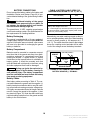
Location, Mounting and Enclosure
The location, mounting and enclosure of a genset
must be such that mounting is secure, engine exhaust and fuel vapors are prevented from entering
the vehicle, cooling air flow is not restricted, and
ready access is afforded for operating the genset
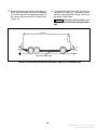
and performing periodic maintenance. Figure 1 illustrates typical genset installations. Commercial
Model HDKAT and HDKAU gensets are suitable for
typical commercial vehicles applications, as shown,
as well as RV-style applications.
clearances, minimum compartment dimensions are:
Height: 22.78 inches (578.6 mm)
Width: 24.73 inches (628.1 mm)
Length: 36.85 inches (936 mm)
5. If the genset is mounted on the floor of the
coach in a compartment inside the envelope of
the living space or cab, provide a vapor-tight,
fire-resistive compartment of 26 gauge galvanized steel or equivalent to isolate the genset
from the vehicle interior. Do not duct genset
cooling air, which can include exhaust gases,
into the vehicle for heating.
1. Orient the genset so that the operator’s console
will be outboard and accessible. There should
be easy access for starting and stopping the
genset, resetting the circuit breaker(s), checking and replenishing engine oil and coolant, replacing the fuses on the back of the access
panel on the console and withdrawing the coolant system pressure cap and fill hose. For Model HDKAT and HDKAU, provide access to the
side service door (Figure 21) and air filter. (A
Remote Air Cleaner Kit 541-0531 is available
from Onan for Models HDKAT and HDKAU).
WARNING EXHAUST GAS AND FIRE ARE
DEADLY! — Install a vapor-tight and fire-resistive barrier of approved materials between the genset and the vehicle interior. —
Do not duct genset cooling air into the vehicle for heating.
6. Provide cutout openings in a compartment floor
that are at least as large as the cooling air inlet
and outlet openings in the bottom of the genset
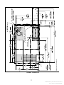
(shaded areas in Figure 2). Frame cross
members must NOT cut across the openings.
2. Locate the genset so that there is sufficient access for battery, fuel, exhaust, remote control
and AC connections. The exhaust tailpipe must
not terminate underneath the vehicle and must
be visible and accessible along its whole length
for inspection and replacement.
7. Make sure that vehicle components located below the genset, including the genset exhaust
tailpipe, will not interfere with draining coolant,
engine oil and removing the oil and fuel filters.
The maintenance door in the base of the genset
must be able to swing open a full 90 degrees
without interference (Models HDKAJ and
HDKAK). (See shaded area in Figure 2 for cutout area.)
3. Support the genset on a structure able to resist
the dynamic weight of the genset (420 lbs
[191 kg]): ±3 g-force (±1260 lbf) vertical and
±1 g-force (±420 lbf) horizontal. The genset is
shipped with four 3/8-16 by 1-1/2 inch threadforming screws to secure it to the supporting
frame or floor.
8. Provide access for removing the two fuel pump
mounting screws so that the genset does not
have to be removed to replace a fuel pump. See
Figure 2.
Design the genset support
structure carefully to prevent the genset
from falling from the vehicle and possibly
causing a serious road accident.
WARNING
9. Locate or shield the genset such that condensate from air conditioners will not drip on it.
4. Provide at least 0.5 inch (12.7 mm) clearance
to the top and 0.25 inch (6.4 mm) clearance to
the sides of the genset. See Figure 2. At these
10. Provide protection from direct road splash if the
genset is located behind a road wheel.
5
Redistribution or publication of this document,
by any means, is strictly prohibited.
—TYPICAL RV INSTALLATIONS—
—TYPICAL COMMERCIAL VEHICLE INSTALLATIONS OF MODEL HDKAT ;& HDKAU—
TYPICAL “HIGH MOUNT”
FIGURE 1. TYPICAL GENSET INSTALLATIONS
6
Redistribution or publication of this document,
by any means, is strictly prohibited.
DIMENSIONS ARE IN INCHES
2 INCH HOLE FOR
OIL DRAIN
TWO 0.79 INCH HOLES FOR FUEL PUMP
MOUNTING SCREW ACCESS
Á
ÁÁ
Á
ÁÁÁ
FIGURE 2. FLOOR PLAN
7
Redistribution or publication of this document,
by any means, is strictly prohibited.
High Mount Installations
area provides the genset’s intake air for cooling
(Figures 3 and 4). At these clearances, minimum compartment dimensions are:
If the genset is to be mounted high on the vehicle
(Model HDKAT and HDKAU only), consider the following:
Width: 24.98 inches (634.5 mm)
Length: 41.35 inches (1050.3 mm)
1. The maximum fuel pump lift is 36 inches
(914.4 mm). An additional fuel pump must be
used for generator sets mounted more than
36 inches (914.4 mm) above the fuel source.
Auxiliary Fuel Pump Kit 541-0530 is available
from Onan.
4. Ducting must be fabricated to exhaust hot air
from the genset. Foam or gasket material must
be used between the duct and the base of the
set to prevent recirculating of exhausted hot air.
See Figures 4 and 5.
5. The exhaust tailpipe must be routed down and
underneath the vehicle and terminate at least
1 inch (25.4 mm) beyond the perimeter of the
vehicle (Page 13). The tail pipe may be routed
inside the hot exhaust duct (Page 10), but not
through the interior of the vehicle. The tail pipe
must be visible and accessible along its entire
length for inspection and replacement.
2. Provide 2.5 inches (63.5 mm) minimum clearance to the sides and rear of the genset, and
0.25 inch (6.35 mm) clearance to the front of the
genset. This area provides the genset’s intake
air for cooling.
3. Risers must be fabricated to raise and support
the genset above the compartment floor. This
8
Redistribution or publication of this document,
by any means, is strictly prohibited.
2.5 IN
(63.5 MM).
2.5 IN
(63.5 MM).
2.5 IN
(63.5 MM).
6 IN
(153 MM).
WELD UP
SEAMS
(TYP.)
6 IN
(153 MM).
10 GAUGE STEEL RISERS
TO SUPPORT WEIGHT OF
SET (4) REQ.
FIGURE 3. HIGH MOUNT INSTALLATION (MODEL HDKAT AND HDKAU ONLY)
9
Redistribution or publication of this document,
by any means, is strictly prohibited.
MINIMUM DUCT SIZE
13.25 X 7.5 INCHES
(336.6 TO 191 MM)
(LENGTH - AS NEEDED UP
TO 60 INCHES {1524 MM})
AIR INTAKE AREA
HOT EXHAUST AREA
NOTES:
D Keep exhausted air away from intake air.
D Test for recirculating air (See Onan Installation Manual 981-0632).
D Use foam/gasketing material to seal duct to base of set.
FIGURE 4. INTAKE AIR – EXHAUST AIR DUCTING (MODEL HDKAT AND HDKAU ONLY)
10
Redistribution or publication of this document,
by any means, is strictly prohibited.
FIGURE 5. EXHAUST AIR OUTLINE DRAWING
11
Redistribution or publication of this document,
by any means, is strictly prohibited.
Exhaust Connections
The exhaust system must be gas-tight and designed to limit entry of exhaust gases into the vehicle.
Onan distributor for approved exhaust system
parts.
WARNING EXHAUST GAS IS DEADLY! Keep
exhaust gases from entering the vehicle. Do not
terminate the exhaust tailpipe underneath the
vehicle or closer than specified to openings into
the vehicle (Figure 9) or route it such that it is
likely to be damaged (Figure10). Use approved
materials and parts only.
The muffler is mounted inside the genset housing
and has a flanged outlet opening (Figure 6). The
muffler is approved by the U.S. Forest Service as a
spark-arrest muffler. (Failure to provide and maintain a spark arrester can be a violation of the law.)
Liability for damage, injury and warranty expense
due to the modification of the exhaust system or due
to the use of unapproved parts becomes the responsibility of the person performing the modification or installing the unapproved parts. Contact an
Tailpipe adapter kits are separately available. Use a
straight adapter for a tailpipe routed up from below
the genset. Use an elbow adapter for a tailpipe
routed through the clearance hole in the right or
back side of the base of the genset. When connecting and routing the tailpipe:
1. Do not connect the genset to the vehicle engine
exhaust system.
CAUTION Interconnecting the engine exhaust systems will allow exhaust condensates and soot to migrate into the engine
that is idle, causing engine damage.
2. Use 1-3/8 inch ID, 18-gauge aluminized steel
tubing or equivalent for the tailpipe. (Do not use
flexible pipe. Flexible pipe is not gas tight or durable.)
3. Secure the tailpipe or adapter flange to the muffler flange with a gasket and two 5/16-18 bolts.
MUFFLER OUTLET FLANGE
TAILPIPE CLEARANCE HOLES
(USE AN ELBOW ADAPTER)
FIGURE 6. EXHAUST CONNECTION AT GENSET
12
Redistribution or publication of this document,
by any means, is strictly prohibited.
4. Use U-bolt muffler clamps to connect sections
of tailpipe. It is recommended that the overlapping pipe be slotted as shown in Figure 7.
5. Use automotive-type tailpipe hangers every 2
to 3 feet (610 to 914 mm). Attach the hangers
to steel framework, not to wood or other combustible material.
6. Do not terminate the tailpipe underneath the
vehicle. Extend it a minimum of 1 inch (25 mm)
beyond the perimeter of the vehicle (Figure 8).
Support the end of the tailpipe such that it cannot be pushed inward and up under the skirt of
the vehicle.
7. Do not route the tailpipe such that it will interfere
with opening the maintenance door or draining
engine oil or coolant or restrict the air inlet.
3/4 INCH (19 MM)
MAXIMUM
SLOT
(BOTH SIDES)
FIGURE 7. EXHAUST TAILPIPE CONNECTIONS
8. Do not route the tailpipe closer than 3 inches
(76 mm) to combustible material (wood, felt,
cotton, organic fibers, etc.) unless it is insulated
or shielded. The temperature rise (above ambient) on adjacent combustible material must not
exceed 117°F (65°C).
9. Do not route the tail pipe near fuel lines or fuel
tanks.
10. Do not terminate the tailpipe such that it is closer than 6 inches (153 mm) to any opening into
the vehicle interior (door, window, vent). See
Figure 9.
LAST TAILPIPE HANGER
CLOSE TO END
11. In “high-mount” applications (Model HDKAT
and HDKAU), the exhaust tailpipe must be
routed down and underneath the vehicle and
terminate at least 1 inch (25.4 mm) beyond the
perimeter of the vehicle (Figure 8). The tail pipe
may be routed inside the hot exhaust duct
(Page 10), but not through the interior of the vehicle. The tail pipe must be visible and accessible along its entire length for inspection and replacement.
1 INCH (25 mm)
MINIMUM
FIGURE 8. TERMINATING THE EXHAUST
TAILPIPE
NO OPENING INTO THE VEHICLE INTERIOR MAY
BE CLOSER THAN 6 INCHES (153 mm) TO THE
END OF THE TAIL PIPE (WITHIN SHADED
AREA)
6 in
153 mm
TAILPIPE
FIGURE 9. MINIMUM DISTANCES TO OPENINGS
13
Redistribution or publication of this document,
by any means, is strictly prohibited.
12. Route the tailpipe such that it will not likely be
struck when the vehicle is moving. At least keep
it out of the approach and departure angles of
the vehicle and above the axle clearance line
(Figure 10).
13. The exhaust back pressure under full load must
not exceed 2 inches (51 mm) water column
(WC) as measured within 6 inches (153 mm) of
the muffler outlet flange.
DEPARTURE
ANGLE
CAUTION Excessive back pressure can
cause loss of performance and engine damage.
APPROACH
ANGLE
AXLE CLEARANCE LINE
FIGURE 10. APPROACH AND DEPARTURE ANGLES AND AXLE CLEARANCE LINE
14
Redistribution or publication of this document,
by any means, is strictly prohibited.
Fuel Connections
Diesel fuel is a combustible and can
cause severe personal injury or death. Do not
smoke or allow any flame, spark, pilot light, arcproducing equipment, electrical switch or other
ignition source around fuel or fuel components,
or in areas sharing ventilation. Keep a type ABC
fire extinguisher handy.
WARNING
Do not interconnect genset and vehicle engine fuel
lines. Follow the vehicle chassis manufacturer’s instructions when making connections to the vehicle
engine fuel tank.
CAUTION Either or both engines could starve
for fuel if the genset and vehicle engine fuel
lines are interconnected. Always use separate
fuel lines or a separate fuel tank for the genset.
To prevent the genset from running the vehicle out
of fuel, do not extend the genset fuel pickup tube
down into the fuel tank as far as the pickup tube for
the vehicle engine.
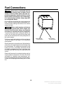
Fuel lines (supply and return) must have at least a
1/4 inch (6.4 mm) ID. See Figure 11 for connections
at the genset.
Run the fuel line at or above the top of the fuel tank to
reduce the risk of siphoning fuel out of the tank if the
line should break. The maximum fuel pump lift is 36
inches (914 mm). An auxiliary fuel pump kit (Kit
541-0530) is available from Onan for generator sets
mounted more than 36 inches (914 mm) above fuel
source.
Route fuel lines away from electrical wiring and hot
engine exhaust components. Fuel lines should be
accessible for inspection and replacement, protected from damage and secured to prevent kinking,
contact with sharp edges and chafing due to vibration.
FUEL RETURN
(1/8 INCH NPT)
FUEL SUPPLY
(1/8 INCH NPT)
FIGURE 11. FUEL CONNECTIONS
15
Redistribution or publication of this document,
by any means, is strictly prohibited.
Electrical Connections
Do not connect the battery cables to the battery until
Installation Review and Startup (Page 22) to prevent accidental starting of the genset during installation.
WARNING Accidental starting of the genset
can cause severe personal injury or death. Do
not connect the starting battery until Installation Review and Startup (Page 22).
GENERATOR CONNECTIONS
The genset is equipped with a terminal block and
conduit connector knockouts for AC power output
connections (Figure 12). See Figure 13 for typical
connections.
Wiring Methods
Follow the National Electrical Code, especially noting the following:
1. Have a qualified electrician supervise and inspect the installation of all AC wiring.
2. Secure only one lead at each AC output terminal. The terminals are suitable for wire sizes up
to No. 6 AWG.
3. Install vibration-proof switches and controls
that won’t open and close circuits when the vehicle is in motion.
4. Provide ground fault circuit interrupters
(GFCIs)for all convenience power receptacles.
5. Route AC wiring, remote control wiring and fuel
lines separately.
6. Seal all conduit openings into the vehicle interior to keep out exhaust gas. Apply silicone rubber or an equivalent type of sealant inside and
outside each conduit connector. (Flexible conduit is not vapor-tight and will allow exhaust gas
to enter along the wires if not sealed.)
AC
TERMINALS
AC WIRING
KNOCKOUTS
CONTROL WIRING
KNOCKOUTS
FIGURE 12. AC OUTPUT BOX
WARNING EXHAUST GAS IS DEADLY!
Seal all wiring openings into the vehicle interior to keep out exhaust gas.
16
Redistribution or publication of this document,
by any means, is strictly prohibited.
power it must have an approved device to keep the
genset and utility from being interconnected. See
Figure 13 for typical connections.
7. Bond the genset and all connected AC and DC
equipment and controls to a common grounding point in accordance with applicable codes.
WARNING Faulty grounding can lead to
fire and electrocution, resulting in severe
personal injury or death. Grounding must
be in accordance with applicable codes.
WARNING Interconnecting the genset and the
public utility (or any other power source) can
lead to the electrocution of personnel working
on the utility lines, damage to equipment and
fire. An approved switching device must be
used to prevent interconnections.
Connecting the Vehicle to Utility Power
When the vehicle has provision for connecting utility
50 AMP SHORE POWER AND TRANSFER SWITCH
TO VEHICLE AC
DISTRIBUTION PANEL
GENSET
TERMINALS
N**
L2
GND
5
120V
GND
L2
L2
N
N
L1
L1
120V
4
3
35A
2
35A
1
120V
TB2*
120V
240V
50 AMP SHORE POWER
GND L1
TRANSFER SWITCH
*
**
DO NOT SECURE MORE THAN ONE CONDUCTOR AT ANY TERMINAL ON TB2
Because L1 and L2 from the genset are in phase, current in the Neutral conductors is the sum of the currents in L1 and L2.
Wiring and equipment must be sized accordingly.
30 AMP SHORE POWER AND TRANSFER SWITCH AND SEPARATE AIR CONDITIONER CIRCUIT
TO REAR
AIR CONDITIONER
GND
N
TO VEHICLE AC
DISTRIBUTION PANEL
L2**
GND L1
N
GND
GND
5
4
35 A
35 A
N
N
3
2
1
TB2*
L1
L1
120V
120V
30 AMP SHORE POWER
120V
GENSET
TERMINALS
TRANSFER SWITCH
*
**
DO NOT SECURE MORE THAN ONE CONDUCTOR AT ANY TERMINAL ON TB2
This circuit has a 30 or 35 amp circuit breaker. Wiring and equipment must be sized and protected accordingly.
FIGURE 13. TYPICAL CONNECTIONS
17
Redistribution or publication of this document,
by any means, is strictly prohibited.
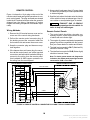
REMOTE CONTROL
5. Keep control leads away from AC power leads
to reduce the possibility of erratic operation due
to induced signals.
Figure 14 shows the 10-pin plug on the end of the
remote control leads and typical connections to a remote control panel. The plug and leads are stowed
inside the AC terminal enclosure when the genset is
shipped from the factory. Harnesses of various
lengths with mating receptacles are available separately.
Wiring Methods
6. Seal the hole where the leads enter the interior
of the vehicle to keep out exhaust gas. Use silicone rubber or an equivalent type of sealant.
WARNING EXHAUST GAS IS DEADLY!
Seal all wiring openings into the vehicle interior to keep out exhaust gas.
Remote Control Panels
1. Remove the AC terminal access cover and remove one of the control wiring knockouts.
1. The control switch should be a two-pole, momentary-contact, center-return/center-off type
of switch with an indicator light.
2. Pull out the remote control connector plug, fit
the bushing around the connector leads into
the knockout slot and secure the access cover.
2. The engine oil pressure and water temperature
gauges should be compatible with the genset.
See your Onan dealer for makes and models.
3. Snap the connector plug and harness receptacle together.
4. If the harness does not have a plug for connections at the control panel, use solder-type butt
connectors and heat-shrink insulation tubing to
connect to the wiring from the remote panel.
Use insulated 18 AWG copper conductors for
the wiring from the remote panel.
3. The total load connected to P8-F (Switched B+)
should not exceed 2 amp.
4. The total load connected to P8-B (Status Light)
should not exceed 2 amp.
GENSET CONNECTOR PLUG (P8)
TYPICAL REMOTE CONTROL PANEL
+
OPTIONAL
VOLTMETER
–
+
GAUGE
COOLANT TEMP
–
Note: To obtain genset status and diagnostics
indication, the remote panel status light must be
connected to P8-B—not to P8-F.
COOLANT TEMP
OIL PRESSURE
SWITCHED B+
STOP
UNUSED
+
GAUGE
OIL PRESSURE
–
+
SWITCH & LIGHT
HOURMETER
–
START
+
STATUS LIGHT
–
UNUSED
GND
FIGURE 14. REMOTE CONTROL CONNECTOR PLUG AND TYPICAL CONNECTIONS
18
Redistribution or publication of this document,
by any means, is strictly prohibited.
BATTERY CONNECTIONS
Do not connect the battery cables to the battery until
Installation Review and Startup (Page 22) to prevent accidental starting of the genset during installation.
Accidental starting of the genset
can cause severe personal injury or death. Do
not connect the starting battery until Installation Review and Startup (Page 22).
WARNING
TABLE 2. BATTERY CABLE SIZES FOR
TEMPERATURES DOWN TO –20° F (–29° C)
TOTAL CABLE LENGTH*
FEET (METERS)
CABLE SIZE
AWG
0 to 10 (0 to 3)
2**
11 to 15 (3 to 4.5)
0
16 to 20 (4.5 to 6)
000
* – Add the negative battery cable lengths with the positive
battery cable lengths for the total.
The genset has a 12 VDC, negative-ground engine
control and cranking system. See Specifications for
the requirements for cranking batteries.
Battery Recharging
The genset is equipped with a 10-amp, regulatedvoltage battery charger if electrical option B183 was
ordered. If the option was not ordered, other means
will have to be provided for recharging the genset
battery or batteries.
** – A total length of up to 20 feet (6 meters) may be used
in warmer climates or when battery capacity totals at least
1000 CCA (Cold Cranking Amps).
Alternatively, use rated cranking current as the basis for calculating battery cable size. Rated cranking
current for these gensets is 180 amperes at 0° F
(–18° C). The cables should be sized so that voltage
across the cranking motor terminals will be within
1 volt of the voltage across the battery terminals.
Battery Compartment
Batteries must be mounted in a separate compartment from that of the genset and away from sparkproducing equipment. A compartment must have
openings of at least 1.7 square inches (11 square
centimetres) at the top and bottom for ventilation of
battery gasses. It should be mounted such that
spills and leaks will not drip acid on fuel lines, wiring
and other equipment that could be damaged.
Arcing can ignite the explosive hydrogen gas given off by the battery, causing severe personal injury. The battery compartment
must be ventilated and must isolate the battery
from spark-producing equipment.
WARNING
SIZE PER TABLE 2
GENSET
+
–
#8 AWG
MINIM
UM
–
+
BAT
VEHICLE FRAME
FIGURE 15. FULL-LENGTH CABLE FROM
BATTERY NEGATIVE (–) TERMINAL
Battery Cables
Size battery cables according to Table 2. The current path between the genset and the negative (–)
battery terminal must also be able to carry full cranking current without causing excessive voltage drop.
It is highly recommended that a full-length cable be
used to connect the genset to the negative (–) battery terminal (Figure 15). Note also that codes may
require bonding conductors from the genset and the
battery to the vehicle frame.
19
Redistribution or publication of this document,
by any means, is strictly prohibited.
If a full-length negative (–) cable is not run from the
battery (Figure 16), all vehicle frame members in
the path of battery cranking currents must have substantial crossections. The electrical resistance of
riveted or bolted frame joints must also be carefully
considered, especially if the joints will be exposed to
corrosive conditions. A cable must be used to connect the frame to the designated negative (–) terminal on the genset (Figure 17). The cable must be
sized according to Table 2. The genset mounting
bolts are not considered adequate means for
bonding the genset to the vehicle frame, either
for the purpose of carrying cranking currents or
for complying with requirements for genset/
system grounding.
GENSET
+
–
SIZE PER TABLE 2
–
+
BAT
VEHICLE FRAME
FIGURE 16. VEHICLE FRAME AS PATH FROM
BATTERY NEGATIVE (–) TERMINAL
Route battery cables away from fuel lines and hot
engine exhaust components. Battery cables should
be accessible for inspection and replacement, protected from damage and secured to prevent chafing
due to vibration.
WARNING Routing battery cables with fuel
lines can lead to fire and severe personal injury
or death. Keep battery cables away from fuel
lines.
Genset Bonding Terminal
The negative (–) battery cable terminal shown in
Figure 17 is also the bonding terminal for grounding
the genset to the vehicle chassis. If the grounding
cable is also going to carry starter motor current, it
must be sized the same as the battery cables.
Connecting Battery and Bonding Cables
Before connecting the battery and genset, clearly
and permanently mark the polarity of the battery
cables. Mark one cable positive (+) on both ends
and the other cable negative (–) on both ends. Mark
bonding cables negative (–) on both ends.
Making sure the battery cables are NOT yet connected at the battery, connect the positive (+) cable
to the POS terminal on the genset (Figure 17) and
the negative (–) cable and bonding cables to the
NEG terminal on the genset. Connect the battery
cables to the battery only at STARTUP (Page 22).
GENSET BONDING
TERMINAL
GENSET BATTERY
CABLE TERMINALS
FIGURE 17. BATTERY CABLE CONNECTIONS
CAUTION Reversing battery connections can
lead to battery charger failure (if so equipped).
20
Redistribution or publication of this document,
by any means, is strictly prohibited.
Specifications
Model HDKAJ / HDKAT
Model HDKAK / HDKAU
GENSET CONTROLLER: Integrated Microprocessor Based Engine and Generator Controller
GENERATOR: Brushless, Exciterless, Bearingless, Permanent Magnet Alternator
AC OUTPUT RATINGS:
Power (@1.0 power factor)
Voltage
Frequency
Number of Phases
Current
Line Circuit Breaker(s)
7500 W
120 volts
60 Hz
1
62.5 ampere
One 2-pole, 30 or 35 amp
8000 W
120 volts
60 Hz
1
66.7 ampere
One 2-pole, 30 or 35 amp
ENGINE: 3-Cylinder In-Line, Water-Cooled, Indirect-Injection, 4-Stroke Cycle Diesel
Bore
Stroke
Displacement
Compression Ratio
2.64 inch (67 mm)
2.68 inch (68 mm)
44 inch3 (719 cc)
23 : 1
3 quart (2.6 l)
4.2 quart (4 l)
0.0065 inch (0.165 mm)
Oil Capacity (with filter)*
Cooling System Capacity**
Intake and Exhaust Valve Lash (Cold)
OPERATING SPEED RANGE:
1600 to 3200 RPM (HDKAJ)
2300 to 3200 RPM (HDKAT)
1600 to 3300 RPM
2300 to 3200 RPM (HDKAU)
.13 gph (.49 l/h)
.49 gph (1.85 l/h)
.96 gph (3.63 l/h)
.13 gph (.49 l/h)
.49 gph (1.85 l/h)
1.02 gph (3.86 l/h)
FUEL CONSUMPTION:
No-load
Half-load (4000 W)
Full-load
DC SYSTEM:
12 volts
450 CCA*** down to 0° F (–17° C)
650 CCA*** down to –20° F (–29° C)
Nominal Battery Voltage
Minimum Battery Capacity
Maximum Regulated-Voltage Battery
Charging Current (Optional)
Fuse F1 (control circuit)
10 ampere
10 ampere mini-bayonet
10 ampere mini-bayonet
25 ampere
Fuse F2 (starter solenoid circuit)
Fuse F3 (glow plug circuit)
WEIGHT AND SIZE:
Weight (wet)
Length x Width x Height
*
**
***
420 lbs (191 kg)
36.3 x 23.6 x 22.3 inch (922 x 599 x 566 mm)
See oil filling instructions.
Includes coolant recovery tank.
Cold Cranking Amps @ 0° F (–17° C)
21
Redistribution or publication of this document,
by any means, is strictly prohibited.
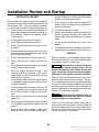
Installation Review and Startup
INSTALLATION REVIEW
Before starting the genset inspect the installation
and check (√) each of the following questions if it can
be answered “YES”. If an item cannot be checked,
provision must be made to satisfy the requirement.
[]
Is the operator’s console easily accessible for
starting and stopping the genset, resetting circuit breakers, checking and adding engine
coolant and oil?
prevent chaffing and contact with sharp edges,
fuel lines and hot exhaust parts?
[]
Is the genset bonding terminal (negative [–]
battery cable terminal) properly grounded to
the vehicle chassis?
[]
Are all fuel connections tight?
[]
Has the fuel lines been secured at sufficient intervals to prevent chaffing and contact with
sharp edges, electrical wiring and hot exhaust
parts?
[]
Is the genset securely bolted in place?
[]
Are all specified clearances provided?
[]
[]
Are the air inlet and outlet openings free of obstructions?
Is the genset protected from direct road
splash?
[]
[]
Does the maintenance access door in the bottom of the genset swing all the way open for fuel
and oil filter replacement?
Is the genset located or shielded such that condensate from air conditioners will not drip on it?
[]
Is there easy access for draining engine oil?
[]
Is there easy access for draining engine coolant?
[]
Are all tailpipe connections tight and all hangers and support straps secure?
[]
Does the tailpipe terminate at least 1 inch
(25 mm) beyond the perimeter of the vehicle
and at least 6 inches (153 mm) away from any
opening into the vehicle?
STARTUP
When all the items on the Installation Review check
list have been checked, connect the battery cables
to the battery, positive (+) cable first.
WARNING Batteries give off explosive gases
that can cause severe personal injury. Do not
smoke near batteries. Keep flames, sparks, pilot
lights, electrical arcs and arc-producing equipment and all other ignition sources well away.
[]
Is the genset located outside the vehicle interior
or separated by approved vapor-tight and fireresistive materials?
[]
Are all openings into the vehicle, such as for AC
wiring, sealed to keep out engine exhaust? Are
AC conduit connectors sealed inside and outside?
[]
Have all AC connections been inspected and
approved?
[]
Has a properly sized battery(ies) been installed
in a ventilated compartment isolated from the
genset?
[]
Have properly sized battery cables been
installed and secured at sufficient intervals to
Read the Operator’s Manual and perform the maintenance and pre-start checks instructed. The genset is shipped from the factory with the proper level
of engine oil, which should nevertheless be checked
before the genset is started. Start and operate the
genset, following all the instructions and safety precautions in the Operator’s Manual.
WARNING EXHAUST GAS IS DEADLY! Do not
operate the genset when the vehicle is indoors
or where exhaust can accumulate.
Check for fuel, coolant and exhaust leaks and unusual noises while the genset is running under full
and intermediate loads. Do not place the genset in
service until all fuel and exhaust leaks have been
fixed and operation is satisfactory.
22
Redistribution or publication of this document,
by any means, is strictly prohibited.
TEMPERATURE TEST
3. Run the genset under full-load, with all service
and compartment doors closed, and record
temperatures every 15 minutes until they stabilize. Temperature is considered stable when
there is no change in three consecutive readings. See Table 3 for an example of how the
data can be recorded.
Conducted this test on the first installation representative of a new application of a genset. Do not continue production until the temperature specifications are met.
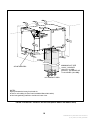
Thermocouples
Measure temperatures with thermocouples not
heavier than No. 24 AWG (0.21 mm2) at the locations shown in Figure 18. When called for, shield the
thermocouple with a 2 inch diameter by 6 inch long
white PVC pipe or equivalent.
1. Locate a shielded thermocouple in the center of
the air inlet opening of the genset to measure inlet air temperature.
2. Locate a shielded thermocouple within 48 inches (1.2 meters) of the inlet air opening and at the
same height to measure ambient air temperature. Make sure it is not affected by warm air discharged from the genset.
3. Locate a thermocouple on the oil dip stick to
measure oil temperature. The thermocouple
should not extend past the ball on the end of the
dip stick.
To prevent severe scalding, always let the engine cool down before removing the coolant pressure cap. Turn the cap
slowly, and do not open it fully until the pressure has been relieved.
WARNING
Temperature Specifications
To determine temperature rises, subtract the ambient air temperature from the other temperatures in
the same column in Table 3.
Inlet Air Temperature Rise: The rise in inlet air
temperature over ambient air temperature must not
exceed 8° F (4.4° C).
Oil Temperature Rise: The rise in engine oil temperature over ambient air temperature must not exceed 190° F (106° C).
Maximum Coolant Temperature: Maximum coolant temperature is 230° F (110° C), at which point
the genset will shut down and fault code
No. 33—High Engine Coolant Temperature—will
be displayed by the status indicator light.
High temperatures and temperature rises indicate
that warm discharge air is recirculating back into the
genset compartment or that the inlet or outlet air
opening is restricted. Find out why and correct as
necessary to meet the temperature specifications.
TABLE 3. TEMPERATURE DATA
TEMPERATURE F° (C°)
4. First relieve coolant system pressure by loosening the coolant pressure cap. Then secure the
cap and remove the coolant hose from the thermostat outlet. Secure a thermocouple so that
the bead is in the center of the thermostat outlet
fitting. Run the leads out between the fitting and
hose and secure the hose with a new hose
clamp.
THERMOCOUPLE
LOCATION
Time Of Reading
INLET AIR
ENGINE COOLANT
ENGINE OIL
AMBIENT AIR
Power Output Ratings
Method
1. Conduct the test at a location where the ambient
air temperature will remain between 60° F and
100° F (16° C and 38° C) during the test.
2. Connect the genset to a load bank that can be
adjusted to apply full rated load.
Maximum genset power (nameplate rating) is
7500 watts in an ambient of 85° F (29° C), but only
6000 watts in an ambient of 120° F (50° C)—the
maximum operating temperature. Also, continuous
operation at up to 80 percent of maximum power
(6000 watts) is acceptable.
23
Redistribution or publication of this document,
by any means, is strictly prohibited.
THERMOCOUPLE SECURED IN
CENTER OF THERMOSTAT OUTLET
SHIELDED THERMOCOUPLE
AT AIR INLET
THERMOCOUPLE SECURED
TO END OF OIL DIP STICK
SHIELDED THERMOCOUPLE LOCATED
48 INCHES (1.2 METERS) MAXIMUM FROM
AIR INLET AND AT SAME HEIGHT
FIGURE 18. THERMOCOUPLE LOCATIONS
24
Redistribution or publication of this document,
by any means, is strictly prohibited.
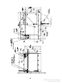
FIGURE 19. OUTLINE DRAWING—BOTTOM (NOT A PLAN VIEW)
25
Redistribution or publication of this document,
by any means, is strictly prohibited.
FIGURE 20. OUTLINE DRAWING—TOP
26
Redistribution or publication of this document,
by any means, is strictly prohibited.
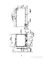
SERVICE DOOR ON
COMMERCIAL MODEL ONLY
FIGURE 21. OUTLINE DRAWING— FRONT AND LEFT SIDES
27
Redistribution or publication of this document,
by any means, is strictly prohibited.
FIGURE 22. OUTLINE DRAWING—RIGHT AND BACK SIDES
28
Redistribution or publication of this document,
by any means, is strictly prohibited.
Cummins Power Generation
1400 73rd Avenue N.E.
Minneapolis, MN 55432
763-574-5000
Fax: 763-528-7229
Cummins and Onan are registered trademarks of Cummins Inc.
Redistribution or publication of this document,
by any means, is strictly prohibited.