1
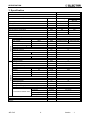
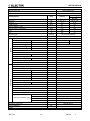
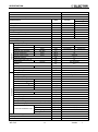
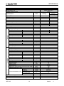
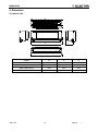
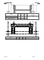
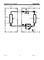
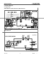
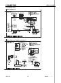
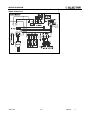
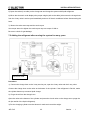
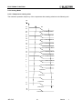
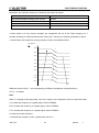
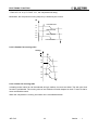
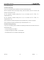
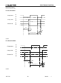
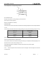
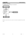
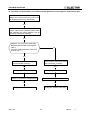
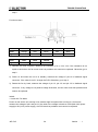
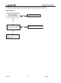
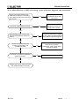
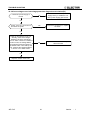
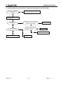
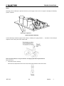
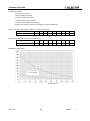
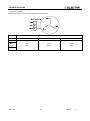
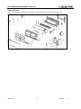
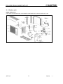
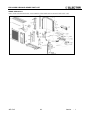
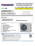
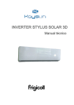
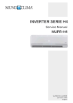
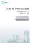
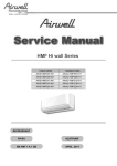
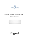
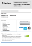
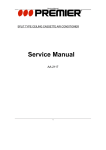
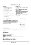
JKD DCI Series Indoor Units Outdoor Units AWSI-JKD009-N11 AWSI-JKD012-N11 AWSI-JKD018-N11 AWSI-JKD024-N11 AWAU-VKD009-H11 AWAU-VKD012-H11 AWAU-VKD018-H11 AWAU-VKD024-H11 REFRIGERANT REFRIGERANT R410A SM JKD DCI 1-A.1 GB HEATPUMP SEP, 2014 CONTENTS 1. Precaution .................................................................................................................................................... 3 1.1 Safety Precaution ........................................................................................................................3 1.2 Warning .......................................................................................................................................3 2. Part Names And Functions ......................................................................................................................... 8 2.1 Model Names of Indoor/Outdoor units .........................................................................................8 2.2 Functions of Indoor/Outdoor units ...............................................................................................8 3. Specification ................................................................................................................................................ 9 4. Dimension .................................................................................................................................................. 13 4.1 Indoor Unit .................................................................................................................................13 4.2 Outdoor Unit ..............................................................................................................................15 5. Refrigerant Cycle Diagram ....................................................................................................................... 16 6. Wiring Diagram .......................................................................................................................................... 17 6.1 Indoor Unit .................................................................................................................................17 6.2 Outdoor Unit ..............................................................................................................................18 7 Installation Details ...................................................................................................................................... 20 7.1 Wrench torque sheet for installation ..........................................................................................20 7.2 Connecting the cables ...............................................................................................................20 7.3 Pipe length and the elevation ....................................................................................................21 7.4 Installation for the first time........................................................................................................22 7.5 Adding the refrigerant after running the system for many years ................................................25 7.6 Re-installation while the indoor unit need to be repaired ...........................................................26 7.7 Re-installation while the outdoor unit need to be repaired .........................................................28 8. Operation Characteristics ......................................................................................................................... 32 9. Electronic function .................................................................................................................................... 33 9.1 Abbreviation ..............................................................................................................................33 9.2 Display function .........................................................................................................................33 9.3 Main Protection .........................................................................................................................34 9.4 Operation Modes and Functions ...............................................................................................36 10. Troubleshooting....................................................................................................................................... 51 10.1 Indoor Unit Error Display .........................................................................................................51 10.2 Diagnosis and Solution............................................................................................................52 11. Exploded View .......................................................................................................................................... 69 11.1 Indoor unit................................................................................................................................69 11.1 Outdoor unit .............................................................................................................................77 PRECAUTION 1. Precaution 1.1 Safety Precaution To prevent injury to the user or other people and property damage, the following instructions must be followed. Incorrect operation due to ignoring instruction will cause harm or damage. Before service the unit, be sure to read this service manual at first. 1.2 Warning Installation Do not use a defective or underrated circuit breaker. Use this appliance on a dedicated circuit. There is risk of fire or electric shock. For electrical work, contact the dealer, seller, a qualified electrician, or an authorized service center. Do not disassemble or repair the product, there is risk of fire or electric shock. Always ground the product. There is risk of fire or electric shock. Install the panel and the cover of control box securely. There is risk of fire of electric shock. Always install a dedicated circuit and breaker. Improper wiring or installation may cause fore or electric shock. Use the correctly rated breaker of fuse. There is risk of fire or electric shock. Do not modify or extend the power cable. There is risk of fire or electric shock. Do not install, remove, or reinstall the unit by yourself (customer). There is risk of fire, electric shock, explosion, or injury. Be caution when unpacking and installing the product. Sharp edges could cause injury, be especially careful of the case edges and the fins on the JKD DCI 3 Version - 1 PRECAUTION condenser and evaporator. For installation, always contact the dealer or an authorized service center. Do not install the product on a defective installation stand. Be sure the installation area does not deteriorate with age. If the base collapses, the air conditioner could fall with it, causing property damage, product failure, and personal injury. Do not let the air conditioner run for a long time when the humidity is very high and a door or a window is left open. Take care to ensure that power cable could not be pulled out or damaged during operation. There is risk of fire or electric shock. Do not place anything on the power cable. There is risk of fire or electric shock. Do not plug or unplug the power supply plug during operation. There is risk of fire or electric shock. Do not touch (operation) the product with wet hands. Do not place a heater or other appliance near the power cable. There is risk of fire and electric shock. Do not allow water to run into electrical parts. It may cause fire, failure of the product, or electric shock. Do not store or use flammable gas or combustible near the product. There is risk of fire or failure of product. Do not use the product in a tightly closed space for a long time. Oxygen deficiency could occur. When flammable gas leaks, turn off the gas and open a window for ventilation before turn the product on. If strange sounds or smoke comes from product, turn the breaker off or disconnect the power supply cable. There is risk of electric shock or fire. Stop operation and close the window in storm or hurricane. If possible, remove the JKD DCI 4 Version - 1 PRECAUTION product from the window before the hurricane arrives. There is risk of property damage, failure of product, or electric shock. Do not open the inlet grill of the product during operation. (Do not touch the electrostatic filter, if the unit is so equipped.) There is risk of physical injury, electric shock, or product failure. When the product is soaked, contact an authorized service center. There is risk of fire or electric shock. Be caution that water could not enter the product. There is risk of fire, electric shock, or product damage. Ventilate the product from time to time when operating it together with a stove etc. There is risk of fire or electric shock. Turn the main power off when cleaning or maintaining the product. There is risk of electric shock. When the product is not be used for a long time, disconnect the power supply plug or turn off the breaker. There is risk of product damage or failure, or unintended operation. Take care to ensure that nobody could step on or fall onto the outdoor unit. This could result in personal injury and product damage. CAUTION Always check for gas (refrigerant) leakage after installation or repair of product. Low refrigerant levels may cause failure of product. Install the drain hose to ensure that water is drained away properly. A bad connection may cause water leakage. Keep level even when installing the product. It can avoid vibration of water leakage. Do not install the product where the noise or hot air from the outdoor unit could damage the neighborhoods. It may cause a problem for your neighbors. JKD DCI 5 Version - 1 PRECAUTION Use two or more people to lift and transport the product. Do not install the product where it will be exposed to sea wind (salt spray) directly. It may cause corrosion on the product. Corrosion, particularly on the condenser and evaporator fins, could cause product malfunction or inefficient operation. Operational Do not expose the skin directly to cool air for long time. (Do not sit in the draft). Do not use the product for special purposes, such as preserving foods, works of art etc. It is a consumer air conditioner, not a precision refrigerant system. There is risk of damage or loss of property. Do not block the inlet or outlet of air flow. Use a soft cloth to clean. Do not use harsh detergents, solvents, etc. There is risk of fire, electric shock, or damage to the plastic parts of the product. Do not touch the metal parts of the product when removing the air filter. They are very sharp. Do not step on or put anything on the product. (outdoor units) Always insert the filter securely. Clean the filter every two weeks or more often if necessary. A dirty filter reduces the efficiency of the air conditioner and could cause product malfunction or damage. Do not insert hands or other objects through air inlet or outlet while the product is operated. Do not drink the water drained from the product. Use a firm stool or ladder when cleaning or maintaining the product. Be careful and avoid personal injury. Replace the all batteries in the remote control with new ones of the same type. Do not mix old and new batteries or different types of batteries. There is risk of fire or explosion. Do not recharge or disassemble the batteries. Do not dispose of batteries in a fire. They may burn of explode. JKD DCI 6 Version - 1 PRECAUTION If the liquid from the batteries gets onto your skin or clothes, wash it well with clean water. Do not use the remote of the batteries have leaked. JKD DCI 7 Version - 1 SPECIFICATION 2. Part Names And Functions 2.1 Model Names of Indoor/Outdoor units Series Inverter Capacity Indoor units Outdoor units 9k AWSI-JKD009-N11 AWAU-VKD009-H11 12k AWSI-JKD012-N11 AWAU-VKD012-H11 18k AWSI-JKD018-N11 AWAU-VKD018-H11 24k AWSI-JKD024-N11 AWAU-VKD024-H11 2.2 Functions of Indoor/Outdoor units Filter 2 ways of drainage Killer Of Formaldehyde Louver Position Memory Function Ionizer(O) Refrigerant Leakage Detect Silver Ico Filter(O) Self-diag. Function Vitamin C Filter(O) Hydrophilic Aluminum Fin 3M HAM Filter(O) Anti-rust Cabinet Bio Filter(O) Valve Protection Cover Golden Fin(O) PTC Heating Belt(O) 1W Standby Compressor Crankcase Heater(O) O: optional function JKD DCI 8 Version - 1 SPECIFICATION 3. Specification Model Indoor Unit Model Outdoor Unit Installation Method of Pipe Units Capacity (1) Pdesign SEER /SCOP (2) Energy efficiency class Annual energy consumption Tbiv Tol Power supply Circuit breaker rating Fan type & quantity Fan speeds H/M/L Air flow (3) H/M/L External static pressure Min-Max Sound power level (4) H/M/L Sound pressure level(5) H/M/L Moisture removal Condensate drain tube I.D Dimensions WxHxD Weight Package dimensions LxWxH Packaged weight Stacking height Refrigerant control Compressor type, model Fan type & quantity Fan speeds H/L Air flow H/L Sound power level(4) H/L Sound pressure level(5) H/L Dimensions WxHxD Weight Package dimensions LxWxH Packaged weight Stacking height Refrigerant type Refrigerant charge (standard connecting tubing length) Additional charge per 1 meter Liquid line Connections between units Suction line Max.tubing length Max.height difference Operation control type Heating elements Others kW kW W/W OUTDOOR INDOOR Characteristics JKD DCI 9 kWh oC oC V/Ph/Hz A RPM m3/hr Pa dB(A) dB(A) l/hr mm mm kg mm kg units RPM m3/hr dB(A) dB(A) mm kg mm kg Units kg(5m) gr / 1m In.(mm) In.(mm) m. m. AWSI-JKD009-N11 AWAU-VKD009-H11 Flared Heating Cooling Average 2.70(1.0~3.2) 2.8(1.0~3.4) 2.7 2.4 5.8 3.8 A+ A 163 884 N/A -7 N/A -15 220-240V/Single/50Hz 10 Cross flow fan x1 1150/1000 /800 1150/1000/ 800 620/540/440 620/540/440 0 58 42/38/30 1.0 16 800 x275x188 6.5 865 x350x265 9.5 8 Capillary tube Rotary DC Inverter Axial x 1 800 1800 64 52 780 x540x250 27.5 910x335x585 30 5 R410A 0.8 15 1/4" (6.35) 3/8"(9.52) 20 8 Remote control kW Version - 1 SPECIFICATION Model Indoor Unit Model Outdoor Unit AWSI-JKD012-N11 AWAU-VKD012-H11 Installation Method of Pipe Flared Characteristics Heating Units Cooling kW 3.2(1.2~3.8) 3.5(1.2~4.0) kW 3.2 3.05 W/W 5.8 3.8 A+ A Average Capacity (1) Pdesign SEER /SCOP (2) Energy efficiency class Annual energy consumption kWh 193 1124 Tbiv oC N/A -7 Tol oC N/A -15 Power supply V/Ph/Hz Circuit breaker rating A Fan type & quantity H/M/L RPM 1200 /1050 /800 1200/1050 /800 Air flow (3) H/M/L m3/hr 630/550/430 630/550/430 Min-Max Pa H/M/L dB(A) 58 H/M/L dB(A) 43/39/31 Moisture removal l/hr 1.1 Condensate drain tube I.D mm 16 mm 800 x275x188 kg 7.5 mm 865 x350x265 kg 9.5 Sound power level INDOOR 10 Cross flow fan x1 Fan speeds External static pressure (4) Sound pressure level(5) Dimensions WxHxD Weight Package dimensions LxWxH Packaged weight Stacking height units Refrigerant control 0 8 Capillary tube Compressor type, model Rotary DC Inverter Fan type & quantity Axial x 1 Fan speeds H/L RPM 800 Air flow H/L m3/hr 1800 Sound power level(4) H/L dB(A) 64 Sound pressure OUTDOOR 220-240V/Single/50Hz level(5) Dimensions H/L dB(A) 53 WxHxD mm 780 x540x250 kg 27.5 LxWxH mm 910x335x585 kg 29.5 Weight Package dimensions Packaged weight Stacking height Units Refrigerant type 5 R410A Refrigerant charge (standard connecting tubing length) kg(5m) 0.95 Additional charge per 1 meter gr / 1m 15 Liquid line In.(mm) 1/4"(6.35) Suction line In.(mm) 3/8"(9.52) Max.tubing length m. 20 Max.height difference m. 8 Connections between units Operation control type Remote control Heating elements kW Others JKD DCI 10 Version - 1 SPECIFICATION Model Indoor Unit Model Outdoor Unit AWSI-JKD018-N11 AWAU-VKD018-H11 Installation Method of Pipe Flared Characteristics Capacity (1) Pdesign SEER /SCOP (2) Cooling kW 5.0(1.4~6.2) 5.1(1.4~6.4) kW 5 4.8 W/W Energy efficiency class Annual energy consumption Heating Units Average 6.5 3.8 A++ A kWh 269 1768 Tbiv oC N/A -6 Tol oC N/A -15 Power supply V/Ph/Hz Circuit breaker rating A Fan type & quantity H/M/L RPM 1100 / 800 / 700 1150 / 800 / 700 Air flow (3) H/M/L m3/hr 730/480/400 760/480/400 Min-Max Pa H/M/L dB(A) 58 H/M/L dB(A) 43/40/33 Moisture removal l/hr 1.7 Condensate drain tube I.D mm 16 mm 940 x275x205 kg 9.5 mm 1015 x350x265 kg 12.5 units 8 Sound power level INDOOR 16 Cross flow fan x1 Fan speeds External static pressure (4) Sound pressure level(5) Dimensions WxHxD Weight Package dimensions LxWxH Packaged weight Stacking height Refrigerant control 0 Capillary tube Compressor type, model Rotary DC Inverter Fan type & quantity Axial x 1 Fan speeds H/L RPM 800 Air flow H/L m3/hr 2200 Sound power level(4) H/L dB(A) 65 Sound pressure OUTDOOR 220-240V/Single/50Hz level(5) Dimensions H/L dB(A) 55 WxHxD mm 760 x590x285 kg 35 LxWxH mm 887x355x645 kg 37.5 Weight Package dimensions Packaged weight Stacking height units Refrigerant type 4 R410A Refrigerant charge (standard connecting tubing length) kg(5m) 1.25 Additional charge per 1 meter gr / 1m 15 Liquid line In.(mm) 1/4"(6.35) Suction line In.(mm) 1/2"(12.7) Max.tubing length m. 20 Max.height difference m. 8 Connections between units Operation control type Remote control Heating elements kW Others JKD DCI 11 Version - 1 SPECIFICATION Model Indoor Unit Model Outdoor Unit AWSI-JKD024-N11 AWAU-VKD024-H11 Installation Method of Pipe Flared Characteristics Heating Units Cooling kW 6.25(2.5~7.2) 7.0(2.5~7.5) kW 6.25 6.3 W/W 6.2 3.8 Average Capacity (1) Pdesign SEER /SCOP (2) Energy efficiency class A++ A kWh 353 2321 Tbiv oC N/A -6 Tol oC N/A -15 Annual energy consumption Power supply V/Ph/Hz Circuit breaker rating A Fan type & quantity INDOOR 25 Cross flow fan x1 Fan speeds H/M/L RPM 1180/1100/ 900 1180/1100 / 900 Air flow (3) H/M/L m3/hr 1150/1050/900 1150/1050/900 External static pressure Min-Max Pa 0 Sound power level (4) H/M/L dB(A) 64 Sound pressure level(5) H/M/L dB(A) 50/47/41 Moisture removal l/hr 2.4 Condensate drain tube I.D mm 16 mm 1045 x315x235 kg 12.2 mm 1135 x315x395 kg 15.3 Dimensions WxHxD Weight Package dimensions LxWxH Packaged weight Stacking height units Refrigerant control 8 Capillary tube Compressor type, model Twin-rotary DC Inverter Fan type & quantity Axial x 1 Fan speeds H/L RPM 850 Air flow H/L m3/hr 2700 Sound power level(4) H/L dB(A) 69 Sound pressure OUTDOOR 220-240V/Single/50Hz level(5) Dimensions H/L dB(A) 58 WxHxD mm 845 x700x320 kg 46.7 LxWxH mm 965x395x755 kg 50 units 3 Weight Package dimensions Packaged weight Stacking height Refrigerant type R410A Refrigerant charge (standard connecting tubing length) kg(5m) 1.95 Additional charge per 1 meter gr / 1m 30 Liquid line In.(mm) 3/8"(9.52) Suction line In.(mm) 5/8"(15.9) Max.tubing length m. 25 Max.height difference m. 10 Connections between units Operation control type Remote control Heating elements kW Others JKD DCI 12 Version - 1 DIMENSION 4. Dimension 4.1 Indoor Unit H D W JKD DCI Model W D H AWSI-JKD009-N11 800 188 275 AWSI-JKD012-N11 800 188 275 AWSI-JKD018-N11 940 205 275 AWSI-JKD024-N11 1045 235 315 13 Version - 1 DIMENSION Model L(mm) R(mm) H(mm) 100 95 45 110 100 45 AWSI-JKD009-N11 AWSI-JKD012-N11 AWSI-JKD018-N11 Dimension of installation hole(mm) ¢65 R L H Model L(mm) R(mm) H(mm) Dimension of installation hole(mm) AWSI-JKD024-N11 293 163 45 ¢65 JKD DCI 14 Version - 1 DIMENSION 4.2 Outdoor Unit More than 30cm More than 60cm (Service space) More than 30cm Fe n ob ce o sta r cle s More than 60cm More than 200cm Model W D H W1 A B AWAU-VKD009-H11 780 250 540 843 549 276 AWAU-VKD012-H11 780 250 540 843 549 276 AWAU-VKD018-H11 760 285 590 823 530 290 AWAU-VKD024-H11 845 320 700 908 560 335 JKD DCI 15 Version - 1 REFRIGERANT CYCLE DIAGRAM 5. Refrigerant Cycle Diagram INDOOR OUTDOOR LIQUID SIDE CHECK VALVE (Heating Model only) 2-WAY VALVE T3 Condenser temp. sensor CAPILIARY TUBE HEAT EXCHANGE (EVAPORATOR) HEAT EXCHANGE (CONDENSER) T4 Ambient temp. sensor T1 Room temp. sensor T2 Evaporator temp. sensor GAS SIDE 4-WAY VALVE 3-WAY VALVE Accumulator Compressor T5 Discharge temp. sensor COOLING HEATING JKD DCI 16 Version - 1 WIRING DIAGRAM 6. Wiring Diagram 6.1 Indoor Unit AWSI-JKD009-N11, AWSI-JKD012-N11, AWSI-JKD018-N11 AWSI-JKD024-N11 JKD DCI 17 Version - 1 WIRI DIAGRAM 6.2 Outdoor Unit AWAU-VKD009-H11 AWAU-VKD012-H11, AWAU-VKD018-H11 JKD DCI 18 Version - 1 WIRING DIAGRAM AWAU-VKD024-H11 JKD DCI 19 Version - 1 INSTALLATION DETAILS 7 Installation Details 7.1 Wrench torque sheet for installation Outside diameter Torque Additional tightening torque mm inch N.cm N.cm Ф6.35 1/4 1500(153kgf.cm) 1600(163kgf.cm) Ф9.52 3/8 2500(255kgf.cm) 2600(265kgf.cm) Ф12.7 1/2 3500(357kgf.cm) 3600(367kgf.cm) Ф15.9 5/8 4500(459kgf.cm) 4700(479kgf.cm) Ф19 3/4 6500(663kgf.cm) 6700(683kgf.cm) 7.2 Connecting the cables The power cord of connect should be selected according to the following specifications sheet. Rated current of appliance Nominal cross-sectional area (mm²) >3 and ≤6 0.75 >6 and ≤10 1 >10 and ≤16 1.5 >16 and ≤25 2.5 The cable size and the current of the fuse or switch are determined by the maximum current indicated on the nameplate which located on the side panel of the unit. Please refer to the nameplate before selecting the cable, fuse and switch. JKD DCI 20 Version - 1 INSTALLATION DETAILS 7.3 Pipe length and the elevation The pipe length and refrigerant amount: Pipe size Model AWSI-JKD009-N11+AWAU-VKD009-H11 Gas Liquid 3/8’’ (Ф9.52) 1/4’’ (Ф6.35) AWSI-JKD012-N11+AWAU-VKD012-H11 Standard length (m) Max. Elevation B (m) Max. Length A (m) Additional refrigerant (g/m) 5 8 20 20 5 8 20 20 AWSI-JKD018-N11+AWAU-VKD018-H11 1/2’’ (Ф12.7) 1/4’’ (Ф6.35) 5 8 20 20 AWSI-JKD024-N11+AWAU-VKD024-H11 3/5’’ (Ф15.9) 3/8’’ (Ф9.52) 5 10 25 40 Caution: The capacity test is based on the standard length and the maximum permissive length is basedon the system reliability. Oil trap: When the outdoor unit is installed above the indoor unit an oil trap is required every 3m along the suction line at the lowest point. In case the indoor unit is installed above the outdoor, no trap is required. JKD DCI 21 Version - 1 INSTALLATION DETAILS 7.4 Installation for the first time Air and moisture in the refrigerant system have undesirable effects as below: ● ● ● ● ● Pressure in the system rises. Operating current rises. Cooling or heating efficiency drops. Moisture in the refrigerant circuit may freeze and block capillary tubing. Water may lead to corrosion of parts in the refrigerant system. Therefore, the indoor units and the pipes between indoor and outdoor units must be leak tested and evacuated to remove gas and moisture from the system. Gas leak check (Soap water method): Apply soap water or a liquid neutral detergent on the indoor unit connections or outdoor unit connections by a soft brush to check for leakage of the connecting points of the piping. If bubbles come out, the pipes have leakage. 1. Air purging with vacuum pump (Indoor unit) (Outdoor unit) (Liquid side) Two-way valve Close (Gas side) Three-way valve Manifold valve Compound meter Pressure gauge -0.1MPa Lo Handle Lo Charge hose Close Hi Handle Hi Charge hose Vacuum pump Vacuum pump 1) Completely tighten the flare nuts of the indoor and outdoor units, confirm that both the 2-way and 3-way valves are set to the closed position. 2) Connect the charge hose with the push pin of handle lo to the 3-way valves gas service port.. 3) Connect the charge hose of handle hi connection to the vacuum pump. 4) Fully open the handle Lo of the manifold valve. 5) Operate the vacuum pump to evacuate. 6) Make evacuation for 30 minutes and check whether the compound meter indicates -0.1Mpa. If JKD DCI 22 Version - 1 INSTALLATION DETAILS the meter does not indicate -0.1Mpa after pumping 30 minutes, it should be pumped 20 minutes more. If the pressure can’t achieve -0.1Mpa after pumping 50 minutes, please check if there are some leakage points. Fully close the handle Lo valve of the manifold valve and stop the operation of the vacuum pump. Confirm that the gauge needle does not move (approximately 5 minutes after turning off the vacuum pump). 7) Turn the flare nut of the 3-way valves about 45°counterclockwise for 6 or 7seconds after the gas coming out, then tighten the flare nut again. Make sure the pressure display in the pressure indicator is a little higher than the atmosphere pressure. Then remove the charge hose from the 3 way valve. 8) Fully open the 2 way valve and 3 way valve and securely tighten the cap of the 3 way valve. 2. Air purging by refrigerant Procedure: 1). Confirm that both the 2-way and 3-way valves are set to the closed position. 2). Connect the charge set and a charging cylinder to the service port of the 3-way valve. 3). Air purging. Open the valves on the charging cylinder and the charge set. Purge the air by loosening the flare nut on the 2-way valve approximately 45’ for 3 seconds then closing it for 1 minute; repeat 3 times. After purging the air, use a torque wrench to tighten the flare nut on the 2-way valve. 4). Check the gas leakage. Check the flare connections for gas leakage. JKD DCI 23 Version - 1 INSTALLATION DETAILS 5). Discharge the refrigerant. Close the valve on the charging cylinder and discharge the refrigerant by loosening the flare nut on the 2-way valve approximately 45’ until the gauge indicates 0.3 to 0.5 Mpa. 6). Disconnect the charge set and the charging cylinder, and set the 2-way and 3-way valves to the open position. Be sure to use a hexagonal wrench to operate the valve stems. 7). Mount the valve stems nuts and the service port cap. Be sure to use a torque wrench to tighten the service port cap to a torque 18N·m. Be sure to check the gas leakage. 3. Adding the refrigerant if the pipe length >5m Electronic scale Procedure: 1). Connect the charge hose to the charging cylinder, open the 2-way valve and the 3-way valve. Connect the charge hose which you disconnected from the vacuum pump to the valve at the bottom of the cylinder. If the refrigerant is R410A, make the cylinder bottom up to ensure the liquid charge. 2). Purge the air from the charge hose. Open the valve at the bottom of the cylinder and press the check valve on the charge set to purge the air (be careful of the liquid refrigerant). 3) Put the charging cylinder onto the electronic scale and record the weight. 4) Operate the air conditioner at the cooling mode. JKD DCI 24 Version - 1 INSTALLATION DETAILS 5) Open the valves (Low side) on the charge set and charge the system with liquid refrigerant. 6).When the electronic scale displays the proper weight (refer to the table), disconnect the charge hose from the 3-way valve’s service port immediately and turn off the air conditioner before disconnecting the hose. 7). Mount the valve stem caps and the service port Use torque wrench to tighten the service port cap to a torque of 18N.m. Be sure to check for gas leakage. 7.5 Adding the refrigerant after running the system for many years Electronic scale Procedure: 1). Connect the charge hose to the 3-way service port, open the 2-way valve and the 3-way valve. Connect the charge hose to the valve at the bottom of the cylinder. If the refrigerant is R410A, make the cylinder bottom up to ensure liquid charge. 2). Purge the air from the charge hose. Open the valve at the bottom of the cylinder and press the check valve on the charge set to purge the air (be careful of the liquid refrigerant). 3) Put the charging cylinder onto the electronic scale and record the weight. JKD DCI 25 Version - 1 INSTALLATION DETAILS 4) Operate the air conditioner at the cooling mode. 5) Open the valves (Low side) on the charge set and charge the system with liquid refrigerant. 6).When the electronic scale displays the proper weight (refer to the gauge and the pressure of the low side), disconnect the charge hose from the 3-way valve’s service port immediately and turn off the air conditioner before disconnecting the hose. 7). Mount the valve stem caps and the service port Use torque wrench to tighten the service port cap to a torque of 18N.m. Be sure to check for gas leakage. 7.6 Re-installation while the indoor unit need to be repaired 1. Collecting the refrigerant into the outdoor unit Procedure 1). Confirm that both the 2-way and 3-way valves are set to the opened position Remove the valve stem caps and confirm that the valve stems are in the opened position. Be sure to use a hexagonal wrench to operate the valve stems. 2). Connect the charge hose with the push pin of handle lo to the 3-way valves gas service port. 3). Air purging of the charge hose. Open the handle Lo valve of the manifold valve slightly to purge air from the charge hose for 5 seconds JKD DCI 26 Version - 1 INSTALLATION DETAILS and then close it quickly. 4). Set the 2-way valve to the close position. 5). Operate the air conditioner at the cooling cycle and stop it when the gauge indicates 0.1MPa. 6). Set the 3-way valve to the closed position immediately Do this quickly so that the gauge ends up indicating 0.3 to 0.5Mpa. Disconnect the charge set, and tighten the 2-way and 3-way valve’s stem nuts. Use a torque wrench to tighten the 3-way valves service port cap to a torque of 18N.m. Be sure to check for gas leakage. 2. Air purging by the refrigerant Procedure: 1). Confirm that both the 2-way and 3-way valves are set to the closed position. 2). Connect the charge set and a charging cylinder to the service port of the 3-way valve Leave the valve on the charging cylinder closed. 3). Air purging. Open the valves on the charging cylinder and the charge set. Purge the air by loosening the flare nut on the 2-way valve approximately 45’ for 3 seconds then closing it for 1 minute; repeat 3 times. JKD DCI 27 Version - 1 INSTALLATION DETAILS After purging the air, use a torque wrench to tighten the flare nut on the 2-way valve. 4). Check the gas leakage Check the flare connections for gas leakage. 5). Discharge the refrigerant. Close the valve on the charging cylinder and discharge the refrigerant by loosening the flare nut on the 2-way valve approximately 45’ until the gauge indicates 0.3 to 0.5 Mpa. 6). Disconnect the charge set and the charging cylinder, and set the 2-way and 3-way valves to the open position Be sure to use a hexagonal wrench to operate the valve stems. 7). Mount the valve stems nuts and the service port cap Be sure to use a torque wrench to tighten the service port cap to a torque 18N.m. Be sure to check the gas leakage. 7.7 Re-installation while the outdoor unit need to be repaired 1. Evacuation for the whole system Procedure: 1). Confirm that both the 2-way and 3-way valves are set to the opened position. 2). Connect the vacuum pump to 3-way valve’s service port. JKD DCI 28 Version - 1 INSTALLATION DETAILS 3). Evacuation for approximately one hour. Confirm that the compound meter indicates -0.1Mpa. 4). Close the valve (Low side) on the charge set, turn off the vacuum pump, and confirm that the gauge needle does not move (approximately 5 minutes after turning off the vacuum pump). 5). Disconnect the charge hose from the vacuum pump. JKD DCI 29 Version - 1 INSTALLATION DETAILS 2. Refrigerant charging Electronic scale Procedure: 1). Connect the charge hose to the charging cylinder, open the 2-way valve and the 3-way valve Connect the charge hose which you disconnected from the vacuum pump to the valve at the bottom of the cylinder. If the refrigerant is R410A, make the cylinder bottom up to ensure liquid charge. 2). Purge the air from the charge hose Open the valve at the bottom of the cylinder and press the check valve on the charge set to purge the air (be careful of the liquid refrigerant). 3) Put the charging cylinder onto the electronic scale and record the weight. 4). Open the valves (Low side) on the charge set and charge the system with liquid refrigerant If the system cannot be charge with the specified amount of refrigerant, or can be charged with a little at a time (approximately 150g each time) , operating the air conditioner in the cooling cycle; however, one time is not sufficient, wait approximately 1 minute and then repeat the procedure. 5).When the electronic scale displays the proper weight, disconnect the charge hose from the 3-way valve’s service port immediately If the system has been charged with liquid refrigerant while operating the air conditioner, turn off the air conditioner before disconnecting the hose. 6). Mounted the valve stem caps and the service port JKD DCI 30 Version - 1 INSTALLATION DETAILS Use torque wrench to tighten the service port cap to a torque of 18N.m. Be sure to check for gas leakage JKD DCI 31 Version - 1 OPERATING CHARACTERISTICS 8. Operation Characteristics Temperature Cooling operation Heating operation Drying operation Mode Room temperature Outdoor temperature ≥17℃ ≤30℃ >10℃ -15℃~50℃ -15℃~30℃ -15℃~50℃ CAUTION: 1. If the air conditioner is used beyond the above conditions, certain safety protection features may come into operation and cause the unit to operate abnormally. 2. The room relative humidity should be less than 80%. If the air conditioner operates beyond this figure, the surface of the air conditioner may attract condensation. Please set the vertical air flow louver to its maximum angle (vertically to the floor), and set HIGH fan mode. 3. The optimum performance will be achieved during this operating temperature zone. JKD DCI 32 Version - 1 ELECTRONIC FUNCTION 9. Electronic function 9.1 Abbreviation T1: Indoor room temperature(RAT) T2: Coil temperature of evaporator (ICT) T3: Coil temperature of condenser (OCT) T4: Outdoor ambient temperature(OAT) T5: Compressor discharge temperature(CTT) 9.2 Display function 9.2.1 Icon explanation on indoor display board. 1. In normal situation, the setting temperature is displayed. (display room temp. in fan mode.) 2* 7 segments display 2. Shows “SC” when self clean function is activated, ”FP” when 8ºC heating function is activated. 3. Shows the alarm code whenever there is an alarm. ION INDICATOR Lights up when ionizer or plasma function is activated. (optional) DEFROSTING Lights up when the unit is under defrosting operation or when the anti-cold INDICATOR air function is activated. RUN INDICATOR Lights up when the unit is in operation. TIMER INDICATOR Lights up when TIMER function is activated. JKD DCI 33 Version - 1 ELECTRONIC FUNCTION 9.3 Main Protection 9.3.1 Time delay at restart for compressor 1 minute delay for the 1st time start-up and 3 minutes delay for others. 9.3.2 Temperature protection of compressor top The unit will stop working when the compressor top temp. protector cut off, and will restart after the compressor top temp. protector restart. 9.3.3 Temperature protection of compressor discharge When the compressor discharge temp. is getting higher, the running frequency will be limited as below rules: ---Compressor discharge temp. T5>115℃ for 5s, compressor stops and restarts up till T5<90℃ ---110<T5<115℃, decrease the frequency to the lower level every 2 minutes. ---105<T5<110℃, keep running at the current frequency. ----T5<105℃, no limit for frequency. 9.3.4 Fan Speed is out of control When Indoor Fan Speed keeps too low (300RPM) for certain time, the unit will stop and the LED will display the failure 9.3.5 Inverter module protection The Inverter module has a protection function about current, voltage and temperature. If these protections happen, the corresponding code will display on indoor unit and the unit will stop working. 9.3.6 Indoor fan delayed open function When the unit starts up, the louver will be active immediately and the indoor fan will open 10s later. If the unit runs in heating mode, the indoor fan will be also controlled by anti-cold wind function. 9.3.7 Compressor preheating functions Preheating permitting condition: If T4(outdoor ambient temperature)<3℃ and the machine connects to power supply newly or if T4< 3℃ and compressor has stopped for over 3 hours, the compressor heating cable will work. Preheating mode: A weak current flow through the coil of compressor from the wiring terminal of the compressor, then the compressor is heated without operation. Preheating release condition: JKD DCI 34 Version - 1 ELECTRONIC FUNCTION If T4>5℃ or the compressor starts running, the preheating function will stop. 9.3.8 Sensor protection at open circuit and breaking disconnection. When there’s one temperature sensor in malfunction, the air conditioner will display error code and will not stop immediately, to avoid the case that the air conditioner is in urgent need. Fault temp. sensor Operation in cooling, drying and fan only mode Operation in heating mode T1 Run supposed T1=26℃ high fan speed Run supposed T1=26℃ medium fan speed T2 Normal During the first 1 minute of compressor operation, indoor fan shuts off. After that, indoor fan runs at medium fan speed for 1 minute and then resume to the setting fan speed. T3 Run with compressor frequency≤F14 3 minutes’ defrosting every 40 minutes when T4<7℃; 2 minutes’ defrosting every 90 minutes when T4≥7℃. T4 Run supposed T4=50℃ Run supposed T4=15℃ TP Run supposed T4=50℃ Run supposed T4=15℃ 9.3.9 Refrigerant leakage detection This function is only active in cooling mode. It can better prevent the compressor being damaged by refrigerant leakage or compressor overload. Open condition: Define the evaporator coil temp.T2 of the compressor just starts running as Tcool. In the beginning 5 minutes after the compressor starts up, if T2 <Tcool-2℃ does not keep continuous 4 seconds and this situation happens 3 times, the display area will show “EC” and AC will turn off. 9.3.10 Zero crossing detection error protection(only for AWSI-JKD009-N11) If AC detects time interval is not correct for continuous 240s, the unit will stop and the LED will display the failure. The correct zero crossing signal time interval should be between 6-13ms. JKD DCI 35 Version - 1 ELECTRONIC FUNCTION 9.4 Operation Modes and Functions 9.4.1 Fan mode (1) Outdoor fan and compressor stop. (2) Temperature setting function is disabled, and no setting temperature is displayed. (3) Indoor fan can be set to high/med/low/auto. (4) The louver operates same as in cooling mode. (5) Auto fan: T1-24 6.0 5.0 4.0 2.5 1.0 JKD DCI H a b c d e 36 (H-L)*0.75+L (H-L)*0.5+L (H-L)*0.25+L L Version - 1 ELECTRONIC FUNCTION 9.4.2 Cooling Mode 9.4.2.1 Compressor running rules The maximum operation frequency of compressor after starting submits to following rule. T4 50 Fmax=T4FREMAX1 49 Fmax=T4FREMAX2 45 44 Fmax=T4FREMAX3 41 40 Fmax=T4FREMAX4 33 32 Fmax=T4FREMAX5 30 29 Fmax=T4FREMAX6 22 20 Fmax=T4FREMAX7 Meanwhile, the maximum frequency is limited by the indoor fan speed. Indoor fan speed Maximum frequency High speed / turbo function No limit Silent mode Fixed at F3 If users switch on AC by remote controller, the compressor will run at the Fmax frequency for 7 minutes according to the outdoor ambient temp. During the 7 minutes, the frequency limitation is active. 7 minutes later, the compressor running frequency will be controlled as below: JKD DCI 37 Version - 1 ELECTRONIC FUNCTION T1-Ts 3.5 A 3.0 2.5 B C 2.0 D 1.5 E 1.0 F 0.5 G 0.0 H -1.0 I -1.5 J While the zones of A,B,C... are corresponding to different compressor running frequency. Note: When T1-Ts keeps in the same temp. zone for 3 minutes, the compressor will run as the below rules: A:Increase the frequency to 3 grade higher until to FREMAX. B~E: Increase the frequency to 2 grade higher until to FREMAX. F~G: Increase the frequency to 1 grade higher until to FREMAX. H: Keep the current frequency. : I: Decrease the frequency to 1 grade lower until to F1. J: Run at F1 for 1h.(if T1-Ts<-2℃, the compressor will stop) Meanwhile, the compressor running frequency is limited by the current. T4 CoolT4Zone5I 50 49 45 CoolT4Zone4I 44 41 CoolT4Zone3I 40 33 CoolT4Zone2I 32 CoolT4Zone1I JKD DCI 38 Version - 1 ELECTRONIC FUNCTION 9.4.2.2 Outdoor fan running rules Cooling Heating 21 A A 28 19 18 B 26 25 16 15 23 22 C C D D 20 19 17 E 13 12 10 B E While A,B,C…means different fan speed of outdoor unit. 9.4.2.3 Indoor fan running rules In cooling mode, indoor fan runs all the time and the speed can be selected as high, medium, low, auto and silent. When the compressor is running, the indoor fan is controlled as below: JKD DCI 39 Version - 1 ELECTRONIC FUNCTION The auto fan acts as below rules: T1-Ts 6.0 5.0 H a 4.0 2.5 1.0 b c d e (H-L)*0.75+L (H-L)*0.5+L (H-L)*0.25+L L 9.4.2.4 Condenser temperature protection ---55℃<T3<60℃, the compressor frequency will decrease to the lower level until to F1 and then runs at F1.If T3<54℃, the compressor will keep running at the current frequency. ---T3<52℃, the compressor will not limit the frequency and resume to the former frequency. ---T3>60℃ for 5 seconds, the compressor will stop until T3<52℃. 9.4.2.5 Evaporator temperature protection ---T2<0℃, the compressor will stop and restart when T2>=5℃. ---0℃≦T2<4℃, the compressor frequency will be limited and decreased to the lower level ---4℃≤T2≤7℃, the compressor will keep the current frequency. ---T2>7℃, the compressor frequency will not be limited. JKD DCI 40 Version - 1 ELECTRONIC FUNCTION 9.4.3 Heating Mode 9.4.3.1 Compressor running rules The maximum operation frequency of the compressor after starting submits to the following rule. T4 Off 34 33 28 27 Fmax=T4FREHEATMAX1 25 24 Fmax=T4FREHEATMAX2 22 21 Fmax=T4FREHEATMAX3 19 18 Fmax=T4FREHEATMAX4 17 16 Fmax=T4FREHEATMAX5 15 14 Fmax=T4FREHEATMAX6 12 11 Fmax=T4FREHEATMAX7 6 5 Fmax=T4FREHEATMAX8 1 0 Fmax=T4FREHEATMAX9 Fmax=F21 -3 -4 Fmax=F22 -7 -8 Fmax=F23 -11 -12 Fmax=F24 -15 -16 Fmax=F25 JKD DCI 41 Version - 1 ELECTRONIC FUNCTION Meanwhile, the maximum frequency is limited by the indoor fan speed. Indoor fan speed Maximum frequency High speed/8 degree heating/ turbo function No limit Medium speed FHeatMaxMidFan Low speed/sleep mode FHeatMaxLowFan Silent mode Fixed at F3 If users switch on AC by remote controller, the compressor will run at the Fmax frequency for 7 minutes according to outdoor ambient temp. During the 7 minutes, the frequency limitation is active. 7 minutes later, the compressor running frequency will be controlled as below: T1-Ts+ΔT +5.0 J +4.5 I +4.0 H +3.5 G +3.0 F +2.5 E +2.0 D C +1.5 B +1.0 +0.5 A While the zones of A,B,C... are corresponding to different compressor running frequency. ΔT=0℃ as default. Note: When T1-Ts keeps in the same temp. zone for 3 minutes, the compressor will run as the below rules: A: Increase the frequency to 3 grade higher until to FREMAX. B~E: Increase the frequency to 2 grade higher until to FREMAX. F~G: Increase the frequency to 1 grade higher until to FREMAX. H: Keep the current frequency. I: Decrease the frequency to the 1 grade lower until to F1. JKD DCI 42 Version - 1 ELECTRONIC FUNCTION J: Run at F1 for 1h.(if T1-Ts-ΔT >6℃, the compressor will stop) Meanwhile, the compressor running frequency is limited by the current. T4 HeatT4Zone4I 15 14 HeatT4Zone3I 10 9.0 HeatT4Zone2I 6.0 5.0 HeatT4Zone1I 9.4.3.2 Outdoor fan running rules Heating 21 E 19 18 D 16 15 C 13 12 B 10 A 9.4.3.3 Indoor fan running rules In heating mode, indoor fan can be selected as high, medium, low, auto and silent. The anti-cold- wind function is preferential. The running rules of anti-cold-wind function depend on both T1 and T2 that is more comfortable control. When the compressor is running, the indoor fan is controlled as below: JKD DCI 43 Version - 1 ELECTRONIC FUNCTION If the compressor stops caused by the room temperature rising, the indoor fan will be forced to run 127 seconds with breeze. During this period, the anti-cold-wind is disabled. Auto fan action in heating mode: T1-Ts+ΔT 0.0 -1.0 L (H+-L)*0.2+L (H+-L)*0.4+L -2.0 -3.0 (H+-L)*0.6+L -4.0 (H+-L)*0.6+L -5.0 -6.0 -6.5 (H+-L)*0.8+L H+ JKD DCI 44 Version - 1 ELECTRONIC FUNCTION 9.4.3.4 Defrosting mode Condition of defrosting: If any one of the following items is satisfied, AC will enter the defrosting mode. After the compressor starts up and keeps running, mark the minimum value of T3 from the 10th minutes to 15th minutes as T30. 1)If the compressor cumulate running time is up to 29 minutes and T3< TCDI1, T3 + T30SUBT3ONE≦T30. 2)If the compressor cumulate running time is up to 35 minutes and T3< TCDI2, T3 + T30SUBT3TWO≦T30. 3)If the compressor cumulate running time is up to 29 minutes and T3< TCDI3 for 3 minutes. 4)If the compressor cumulate running time is up to 120 minutes and T3<-15℃. Condition of ending defrosting: If any one of the following items is satisfied, the defrosting will finish and the machine will turn to normal heating mode. ----T3 rises to be higher than TCDE1℃. ----T3 keeps to be higher than TCDE2℃ for 80 seconds. ----The machine has run for 10 minutes in defrosting mode. JKD DCI 45 Version - 1 ELECTRONIC FUNCTION Defrosting action: For 9k,12k models: on Compressor 4-way valve Outdoor fan off on off on off xx 10s 10s no longer than 10m 30s xx=20. For 18k,24k models: on Compressor 4-way valve Outdoor fan off on off on off xx 10s 10s no longer than 10m 30s xx=20 JKD DCI 46 Version - 1 ELECTRONIC FUNCTION 9.4.3.5 Evaporator coil temperature protection T2 Off TEstop Decrease TEdown Hold TEnorm Resume Off: Compressor stops. Decrease: Decrease the running frequency to the lower level. Hold: Keep the current frequency. Resume: No limitation for frequency. 9.4.4 Auto-mode This mode can be chosen with remote controller and the setting temperature can be changed between 17~30℃. In auto mode, the machine will choose cooling, heating or fan-only mode according to ΔT (ΔT =T1-Ts). ΔT=T1-Ts Running mode ΔT>1℃ Cooling -1<ΔT≤1℃ Fan-only ΔT≤-1℃ Heating Indoor fan will run at auto fan of the relevant mode. The louver operates same as in relevant mode. If the machine switches mode between heating and cooling, the compressor will keep stopping for 15 minutes and then choose mode according to T1-Ts. If the setting temperature is modified, the machine will choose running function again. 9.4.5 Drying mode 9.4.5.1 Indoor fan speed is fixed at breeze and can’t be changed. The louver angle is the same as in cooling mode. JKD DCI 47 Version - 1 ELECTRONIC FUNCTION 9.4.5.2 Compressor running rules T1-Ts 2.5 F7 2.0 1.5 F5 1.0 0.5 F3 0.0 F1 9.4.5.3 Low indoor room temperature protection In drying mode, if room temperature is lower than 10℃, the compressor will stop and not resume until room temperature exceeds 12℃. 9.4.5.4 Evaporator anti-freezing protection, condenser high temperature protection and outdoor unit frequency limit are active and the same as that in cooling mode. 9.4.5.5 The outdoor fan operates the same as in cooling mode. 9.4.6 Forced operation function 9.4.6.1 Enter forced operation function: When the machine is off, pressing the touch button will carry the machine to forced auto mode. If pressing the button once again within 5 seconds, the machine will turn into forced cooling mode. In forced auto, forced cooling or any other operation mode, pressing touch button will turn off the machine. 9.4.6.2 In forced operation mode, all general protections and remote control are available. 9.4.6.3 Operation rules: Forced cooling mode: The compressor runs at F2 frequency and indoor fan runs as breeze. After running for 30 minutes. the machine will turn to auto mode as 24℃ setting temperature. Forced auto mode: The action of forced auto mode is the same as normal auto mode with 24℃ setting temperature. 9.4.7 Timer function 9.4.7.1 Timing range is 24 hours. JKD DCI 48 Version - 1 ELECTRONIC FUNCTION 9.4.7.2 Timer on. The machine will turn on automatically when reaching the setting time. 9.4.7.3 Timer off. The machine will turn off automatically when reaching the setting time. 9.4.7.4 Timer on/off. The machine will turn on automatically when reaching the setting “on” time, and then turn off automatically when reaching the setting “off” time. 9.4.7.5 Timer off/on. The machine will turn off automatically when reaching the setting “off” time, and then turn on automatically when reaching the setting “on” time. 9.4.7.6 The timer function will not change the AC current operation mode. Suppose AC is off now, it will not start up firstly after setting the “timer off” function. And when reaching the setting time, the timer LED will be off and the AC running mode has not been changed. 9.4.7.7 The setting time is relative time. 9.4.8 Sleep function mode 9.4.8.1 Operation time in sleep mode is 7 hours. After 7 hours the AC quits this mode and turns off. 9.4.8.2. Operation process in sleep mode is as follow: When cooling, the setting temperature rises 1℃ (be lower than 30℃) every one hour, 2 hours later the setting temperature stops rising and indoor fan is fixed as low speed. When heating, the setting temperature decreases 1℃ (be higher than 17℃) every one hour, 2 hours later the setting temperature stops rising and indoor fan is fixed as low speed. (Anti-cold wind function has the priority) 9.4.8.3 Timer setting is available 9.4.8.4 When user uses timer off function in sleep mode (or sleep function in timer off mode), if the timing is less than 7 hours, sleep function will be cancelled when reaching the setting time. If the timing is more than 7 hours, the machine will not stop until reaches the setting time in sleep mode. 9.4.9 Auto-Restart function The indoor unit is equipped with auto-restart function, which is carried out through an auto-restart module. In case of a sudden power failure, the module memorizes the setting conditions before the power failure. The unit will resume the previous operation setting (not including swing function) automatically after 3 minutes when power returns. If the memorization condition is forced cooling mode, the unit will run in cooling mode for 30 minutes and turn to auto mode as 24℃ setting temp. If AC is off before power off and AC is required to start up now, the compressor will have 1 minute delay when power on. Other conditions, the compressor will have 3 minutes delay when restarts. JKD DCI 49 Version - 1 ELECTRONIC FUNCTION 9.4.10 8℃ Heating In heating operation, the preset temperature of the air conditioner can be as lower as 8℃, which keeps the room temperature steady at 8℃ and prevents household things freezing when the house is unoccupied for a long time in severe cold weather. 9.4.11 Frequency limitation protection V Normal VOLT_RST1_ADD VOLT_LIM1_ADD VOLT_LIM_FREQ1_ADD VOLT_RST2_ADD VOLT_LIM2_ADD VOLT_LIM_FREQ2_ADD The PCB will detect the voltage of power supply and adjust the compressor running frequency to protect the system. In the first 10 seconds after power on, this protection is inactive. When this protection happens, it will last 3 minutes and then the PCB will detect the power supply voltage again. JKD DCI 50 Version - 1 TROUBLE SHOOTING 10. Troubleshooting 10.1 Indoor Unit Error Display Operation lamp Timer lamp Display LED STATUS ☆ 1 time X E0 Indoor unit EEPROM parameter error ☆ 2 times X E1 Indoor / outdoor units communication error ☆ 3 times X E2 ☆ 4 times X E3 ☆ 5 times X E4 Zero crossing signal detection error(only for AWSI-JKD009-N11 ) Indoor fan speed has been out of control Open circuit or short circuit of indoor room temperature T1 sensor Open circuit or short circuit of evaporator coil temperature T2 ☆ 6 times X E5 sensor ☆ 7 times X EC ☆ 2 times O F1 Refrigerant Leakage Detection Open circuit or short circuit of outdoor ambient T4 temperature sensor Open circuit or short circuit of condenser coil temperature T3 ☆ 3 times O F2 sensor Open circuit or short circuit of compressor discharge T5 ☆ 4 times O F3 temperature sensor ☆ 5 times O F4 Outdoor unit EEPROM parameter error ☆ 6 times O F5 Outdoor fan speed has been out of control ☆ 1 times ☆ P0 IPM malfunction or IGBT over-strong current protection ☆ 2 times ☆ P1 Over voltage or over low voltage protection ☆ 3 times ☆ P2 High temperature protection of compressor top diagnosis and solution(Only for AWSI-JKD024-N11 models) ☆ 5 times ☆ P4 O(light) JKD DCI Inverter compressor drive error X(off) 51 ☆(flash) Version - 1 TROUBLE SHOOTING 10.2 Diagnosis and Solution 10.2.1 EEPROM parameter error diagnosis and solution(E0) Shut off the power supply and turn it on 5 seconds later. Is it still displaying the error code? Yes If the EEPROM chip is welded on main PCB, replace the main PCB directly. Otherwise, check whether the EEPROM chip plugged in main PCB well? No Correct the connection. Yes Replace the indoor main PCB. EEPROM: a read-only memory whose contents can be erased and reprogrammed using a pulsed voltage. JKD DCI 52 Version - 1 TROUBLE SHOOTING 10.2.2 Indoor unit and outdoor unit communication protection error diagnosis and solution (E1) Power off, then turn on the unit 5 seconds later(reconnect the power wire).Is the error still displaying after several minutes? Yes Check all the wirings between indoor and outdoor, indoor main PCB and outdoor main PCB following the wiring diagram. Are all the wirings connected correctly? Yes Measure Vs, is it moving alternately between positive value and negative value? (Vs is the voltage between S and N of outdoor unit.) No Yes Is the wiring to the outdoor m a i n PCB connected correctly? Is the wiring to the indoor main PCB connected correctly? Yes Yes Change the outdoor main PCB. Change the indoor main PCB. Power on. Is the error extinguished? Power on. Is the error extinguished? No No Change the indoor main PCB. Change the outdoor main PCB. JKD DCI 53 Version - 1 TROUBLE SHOOTING 10.2.3 Zero crossing detection error diagnosis and solution(E2) Check if the connections and power supply is normal? Correct the connections. Turn on the unit when the power supply is good. No Yes Indoor main PCB is defective. Replace indoor main PCB. 10.2.4 Fan speed has been out of control diagnosis and solution (E3/F5) Shut off the power supply and turn it on 5 seconds later. Is it still displaying the error code? No The unit operates normally. Yes Shut off the power supply, rotate the fan by hand. Does it rotate properly? No Find out the cause and have it solved. For example, check whether the fan is blocked or the bearing is broken? No Correct the connections. Yes Check the wires of fan motor. Are all the connections good? Yes Check whether the fan motor is normal through index 1? No Replace the fan motor If the malfunction is still existing, replace the main PCB No Yes Check whether the main PCB is normal through index 2? No Replace the main PCB. The malfunction is solved? Yes JKD DCI 54 Version - 1 TROUBLE SHOOTING Index 1: 1. Indoor AC Fan Motor Measure the resistance value of each winding by using the tester. 2.Outdoor or indoor DC Fan Motor (control chip is in fan motor) Measure the resistance value of each winding by using the tester. If any resistance value is zero, the fan motor must have problems and need to be replaced. 3. Outdoor or indoor DC Fan Motor (control chip is in on PCB) For WZDK36-38G-W 1) Release the UVW connector. Measure the resistance of U-V, U-W, V-W. If the resistance is not equal to each other, the fan motor must has problems and need to be replaced. Otherwise, go to JKD DCI 55 Version - 1 TROUBLE SHOOTING step 2. For other motors: NO. 1 2 3 4 5 Color Orange Grey White Pink Black Signal Hu Hv Hw Vcc GND Color Red Blue Yellow Signal W V U 1) Release the UVW connector. Measure the resistance of U-V, U-W, V-W. If the resistance is not equal to each other, the fan motor must has problems and need to be replaced. Otherwise, go to step 2. 2) Power on and when the unit is in standby, measure the voltage of pin4-5 in feedback signal connector. If the value is not 5V, change the PCB. Otherwise, go to step 3. 3) Rotate the fan by hand, measure the voltage of pin1-5, pin 2-5 and pin 3-5 in feedback signal connector. If any voltage is not positive voltage fluctuation, the fan motor must has problems and need to be replaced. Index2: 1: Indoor AC Fan Motor Power on and set the unit running in fan mode at high fan speed. After running for 15 seconds, measure the voltage of pin1 and pin2. If the value of the voltage is less than 100V(208~240V power supply)or 50V(115V power supply), the PCB must has problems and need to be replaced. JKD DCI 56 Version - 1 TROUBLE SHOOTING 2. Indoor or Outdoor DC Fan Motor(control chip is in fan motor) Power on and when the unit is in standby, measure the voltage of pin1-pin3, pin4-pin3 in fan motor connector. If the value of the voltage is not in the range showing in below table, the PCB must has problems and need to be replaced. DC motor voltage input and output NO. Color Signal Voltage 1 Red Vs/Vm 280V~380V 2 --- --- --- 3 Black GND 0V 4 White Vcc 14-17.5V 5 Yellow Vsp 0~5.6V 6 Blue FG 14-17.5V JKD DCI 57 Version - 1 TROUBLE SHOOTING 10.2.5 Open circuit or short circuit of temperature sensor diagnosis and solution (E4/E5/F1/F2/F3) Check the connections between temperature sensor and PCB. Are the connections good? No Correct the connections. Yes Check the resistance value of the sensor via table1 and table 2, is it normal? Yes Replace indoor or outdoor PCB. No Replace the sensor and check if the problem happen again? JKD DCI 58 Version - 1 TROUBLE SHOOTING 10.2.6 Refrigerant Leakage Detection diagnosis and solution (EC) Shut off the power supply and turn it on 5 seconds later. Is it still displaying the error code? Yes Is there cool air blowing out from indoor air outlet? Yes No Yes Is there any leakage? Especially the connection parts, such as the gas valve and the liquid valve. No Check if T2 sensor is well fixed. Correct the installation or replace T2 sensor. Does the problem remain again? Replace indoor PCB. Yes Repair the leakage and recharge the refrigerant. Is there any block i n g ? (Such as the capillary or the welded points of the pipes.) Yes Clear the blocking. JKD DCI 59 Version - 1 TROUBLE SHOOTING 10.2.7 IPM malfunction or IGBT over-strong current protection diagnosis and solution(P0) Check if the wiring between main PCB and compressor connected by error and if the wires and connectors are broken? Yes Correct the connection or replace the wires and connectors. No Correct the installation, tighten the screws and apply silicon grease. No Check if the IPM installed correctly. Yes IPM continuity check. Check if the IPM terminal resistance values are uniform. No Replace the IPM board or replace the main PCB if the IPM board and main PCB are integrated together. No Refer to the solution of fan speed has been out of control malfunction . Find out the cause and have it solved. No Replace the compressor. Yes Check if the outdoor fan runs properly or the outdoor unit ventilation is good. Yes Check if the compressor resistance values are uniform . Yes Replace the outdoor main PCB if the main PCB and IPM are separate. JKD DCI 60 Version - 1 TROUBLE SHOOTING 10.2.8 Over voltage or too low voltage protection diagnosis and solution(P1) Check if the power supply is normal. No Disconnect the unit with power supply and try to restart the unit when power supply gets normal. No Correct the connections or replace the wires. Yes Check if all the connections and wires are good? Yes Power on and when the unit is in standby, check if the voltage between P and N is around DC 310V or 340V or 380V? For different kinds of units, the voltage differs. Consult with technical engineer to get definite value. Then start up the unit, measure the voltage between P and N. Is it in 220V~400V? Replace the IPM board if it is separate with main PCB. No Yes Replace outdoor mainl PCB. JKD DCI 61 Version - 1 TROUBLE SHOOTING 10.2.9 High temperature protection of compressor top diagnosis and solution(P2) Check if the air flow system of indoor and outdoor units are obstructed? Clear up the air inlet and outlet or the heat exchanger of indoor and outdoor units. Yes No Turn off the power supply and turn it on 10 minutes later. Yes Check if the unit can start normally. Check if all the connection, especially the connection of OLP (Over Load Protector) sensor is good. No Yes Yes Check if the refrigerant charge volume is normal? Measure the resistance between the two ports of the OLP. Is it zero? No No Correct the connection. Replace the OLP. No Yes Yes Refrigerant system is blocked, such as capillary or welded point of pipes. JKD DCI Replace the outdoor control PCB. Recharge the correct refrigerant volume. 62 Version - 1 TROUBLE SHOOTING 10.2.10 Inverter compressor drive error diagnosis and solution(P4) Check if the wiring between main PCB and compressor connected by error and if the wires and connectors are broken? Yes Correct the connection or replace the wires and connectors. No Correct the installation, tighten the screws and apply silicon grease. No Check if the IPM installed correctly. Yes IPM continuity check. Check if the IPM terminal resistance values are uniform. No Replace the IPM board or replace the main PCB if the IPM board and main PCB are integrated together. No Refer to the solution of fan speed has been out of control malfunction . Find out the cause and have it solved. No Replace the compressor. Yes Check if the outdoor fan runs properly or the outdoor unit ventilation is good. Yes Check if the compressor resistance values are uniform . Yes Replace the outdoor main PCB if the main PCB and IPM are separate. JKD DCI 63 Version - 1 TROUBLE SHOOTING Safety Electricity power is still kept in capacitors even the power supply is shut off. Do not forget to discharge the electricity power in capacitor. Electrolytic Capacitors (HIGH VOLTAGE! CAUTION!) Connect discharge resistance (approx.100Ω 40W) or soldering iron (plug) between +, - terminals of the electrolytic capacitor on the contrary side of the outdoor PCB. Note: The picture above is only for reference. The plug of your side may be different. Main parts check 1. Temperature sensor checking Disconnect the temperature sensor from PCB, measure the resistance value with a tester. JKD DCI 64 Version - 1 TROUBLE SHOOTING Temperature Sensors. Room temp.(T1) sensor, Indoor coil temp.(T2) sensor, Outdoor coil temp.(T3) sensor, Outdoor ambient temp.(T4) sensor, Compressor discharge temp.(T5) sensor. Measure the resistance value of each winding by using the multi-meter. Table 1: Some frequently-used R-T data for T1,T2,T3 and T4 sensor: Temperature (℃) 5 10 15 20 25 30 40 50 60 Resistance Value (KΩ) 26.9 20.7 16.1 12.6 10 8 5.2 3.5 2.4 Table 2: Some frequently-used R-T data for T5 sensor: Temperature (℃) 5 15 25 35 60 70 80 90 100 Resistance Value (KΩ) 141.6 88 56.1 36.6 13.8 9.7 6.9 5 3.7 Resistance value (KΩ) T5 T1,T2,T3,T4 Temperature (℃) JKD DCI 65 Version - 1 TROUBLE SHOOTING Spec. Code 2T0032300899 2T0032400280 2T0032800707 2T0032900568 Model AWSI-JKD009-N11 AWSI-JKD012-N11 AWSI-JKD018-N11 AWSI-JKD024-N11 Compressor ASN108D22UEZ ASN108D22UEZ DA130M1C-31FZ DA150S1C-20FZ RPG20E WZDK20-38G WZDK30-38G WZDK58-38G (☆) (☆) (☆) Indoor fan motor Outdoor fan WZDK36-38G-W WZDK36-38G-W WZDK36-38G-W WZDK50-38G motor (★) (★) (★) (☆) Note: The motor marked “★”means DC fan motor with control chip in the PCB while the one marked “☆” means DC fan motor with control chip in the fan motor. JKD DCI 66 Version - 1 TROUBLE SHOOTING 2. Compressor checking Measure the resistance value of each winding by using the tester. Position Resistance Value ASN108D22UEZ DA130M1C-31FZ DA150S1C-20FZ Blue - 1.5Ω 1.77Ω 0.95Ω Black (20℃) (20℃) (20℃) Blue - Red Red - Blue JKD DCI 67 Version - 1 TROUBLE SHOOTING 3.IPM continuity check Turn off the power, let the large capacity electrolytic capacitors discharge completely, and dismount the IPM. Use a digital tester to measure the resistance between P and UVWN; UVW and N. Digital tester (+)Red (-)Black N P Normal resistance value U V ∞ (Several MΩ) W Digital tester (+)Red (-)Black ∞ U V Normal resistance value N (Several MΩ) W 4.Indoor AC Fan Motor Measure the resistance value of each winding by using the tester. Position Resistance Value RPG20E Black - Red White - Black JKD DCI 430Ω±8% (20℃) 388Ω±8% (20℃) (Brand: Dayang) (Brand: Weiling) 370Ω±8% (20℃) 360Ω±8% (20℃) (Brand: Dayang) (Brand: Weiling) 68 Version - 1 EXPLODED VIEW AND SPARE PART LIST 11. Exploded View 11.1 Indoor unit AWSI-JKD009-N11 ONLY FOR STANDARD BOM, CUSTOMIZED FEATURE MAY CHANGE THE PART LIST JKD DCI 69 Version - 1 EXPLODED VIEW AND SPARE PART LIST No. Part 1 Panel assembly 1 3 Display box assembly 1 203332591125 3.1 Display board assembly 1 201333090687 4 Cover of electrical equipment 1 201119901024 5 Panel frame assembly 1 201132591041 5.1 Screw cap 2 201119900950 6 Drain hose 1 201101020038 7 Pipe Nut 1 201600330002 7 Pipe Nut 1 201600330001 8 Fix clamp of temperature sensor 1 201102000305 9 Evaporator assembly 1 201532390220 10 Fan motor cover 1 201132490127 11 Asynchronous motor 1 202400400213 12 Bearing holder 1 201119900952 13 Bearing base 1 202719900606 14 Cross flow fan 1 201100200306 15 Horizontal louver 1 201132591044 16 Chassis assembly 1 201132591057 16.1 Louver motor 1 202400200031 17 Pipe clamp board 1 201119900949 18 Installation plate 1 201232590037 19 Electronic control box assembly 1 203332391198 19.1 Electronic control box I 1 201132490125 19.2 Electronic control box II 1 201132490150 19.3 Indoor main control board assembly 1 201332391780 19.4 Ambient temperature sensor assembly 1 202433190000 19.5 Pipe temperature sensor assembly 1 202301300426 19.6 Wire joint 1 202301450119 20 Cover of electronic control box 1 201132490126 21 Remote Controller 1 203355000031 22 Seal ring 1 202720090001 23 Drain joint 1 201101020011 24 Air freshening filter 1 201131410703 25 Air filter(left) 1 201132591042 26 Air filter(right) 1 201132591040 JKD DCI Name Quantity 70 BOM Code Version - 1 EXPLODED VIEW AND SPARE PART LIST AWSI-JKD012-N11 ONLY FOR STANDARD BOM, CUSTOMIZED FEATURE MAY CHANGE THE PART LIST JKD DCI 71 Version - 1 EXPLODED VIEW AND SPARE PART LIST No. Part 1 Panel assembly 1 3 Display box assembly 1 203332591125 3.1 Display board assembly 1 201333090687 4 Cover of electrical equipment 1 201119901024 5 Panel frame assembly 1 201132591041 5.1 Screw cap 2 201119900950 6 Drain hose 1 201101020038 7 Pipe Nut 1 201600330002 7 Pipe Nut 1 201600330001 8 Fix clamp of temperature sensor 1 201102000305 9 Evaporator assembly 1 201532390220 10 Fan motor cover 1 201132490127 11 Brushless DC Motor 1 202400370025 12 Bearing holder 1 201119900952 13 Bearing base 1 202719900606 14 Cross flow fan 1 201100200306 15 Horizontal louver 1 201132591044 16 Chassis assembly 1 201132591057 16.1 Louver motor 1 202400200031 17 Pipe clamp board 1 201119900949 18 Installation plate 1 201232590037 19 Electronic control box assembly 1 203332490311 19.1 Electronic control box I 1 201132490125 19.2 Electronic control box II 1 201132490150 19.3 Indoor main control board assembly 1 201332490360 19.4 Ambient temperature sensor assembly 1 202433190000 19.5 Pipe temperature sensor assembly 1 202301300426 19.6 Wire joint 1 202301450119 20 Cover of electronic control box 1 201132490126 21 Remote Controller 1 203355000031 22 Seal ring 1 202720090001 23 Drain joint 1 201101020011 24 Air freshening filter 1 201131410703 25 Air filter(left) 1 201132591042 26 Air filter(right) 1 201132591040 JKD DCI Name Quantity 72 BOM Code Version - 1 EXPLODED VIEW AND SPARE PART LIST AWSI-JKD018-N11 ONLY FOR STANDARD BOM, CUSTOMIZED FEATURE MAY CHANGE THE PART LIST JKD DCI 73 Version - 1 EXPLODED VIEW AND SPARE PART LIST No. Part 1 Panel assembly 1 2 Air filter 2 201132790664 3 Display box assembly 1 203332890588 3.1 Display board assembly 1 201333090687 4 Cover of electrical equipment 1 201119901024 5 Panel frame assembly 1 201132790667 5.1 Screw cap 2 201119900950 6 Drain hose 1 201101020038 7 Pipe Nut 1 201600330003 7 Pipe Nut 1 201600330001 8 Fix clamp of temperature sensor 1 201102000305 9 Evaporator assembly 1 201532890160 10 Fan motor cover 1 201132790663 11 Brushless DC Motor 1 202400300517 12 Bearing holder 1 201119900952 13 Bearing base 1 202719900606 14 Cross flow fan 1 201100200322 15 Horizontal louver 1 201132790665 16 Chassis assembly 1 201132790680 16.1 Louver motor 1 202400200031 17 Pipe clamp board 1 201119900949 18 Installation plate 1 201232790013 19 Electronic control box assembly 1 203332890706 19.1 Electronic control box I 1 201132490125 19.2 Electronic control box II 1 201132490150 19.3 Indoor main control board assembly 1 201332890811 19.4 Ambient temperature sensor assembly 1 202433190000 19.5 Pipe temperature sensor assembly 1 202301300426 19.6 Wire joint 1 202301450119 20 Cover of electronic control box 1 201132490126 21 Remote Controller 1 203355000031 22 Seal ring 1 202720090001 23 Drain joint 1 201101020011 24 Air freshening filter 1 201131410703 JKD DCI Name Quantity 74 BOM Code Version - 1 EXPLODED VIEW AND SPARE PART LIST AWSI-JKD024-N11 ONLY FOR STANDARD BOM, CUSTOMIZED FEATURE MAY CHANGE THE PART LIST JKD DCI 75 Version - 1 EXPLODED VIEW AND SPARE PART LIST No. Part 1 Panel assembly 1 2 Air filter(right) 1 201133091043 3 Air filter(left) 1 201133091044 4 Display box assembly 1 203333090474 4.1 Display board assembly 1 201333090687 5 Cover of electrical equipment 1 201133091048 6 Panel frame assembly 1 201133091041 6.1 Screw cap 3 201119900950 7 Horizontal louver 1 201133090987 8 Air outlet assembly 1 201133091126 8.1 Louver motor 1 202400200120 9 Drain hose 1 201101020038 10 Pipe Nut 1 201600330004 10 Pipe Nut 1 201600330002 11 Fix clamp of temperature sensor 1 201102000305 12 Evaporator assembly 1 201533090140 13 Fan motor cover 1 201133090980 14 Fixing board of fan motor 1 201133090167 15 Brushless DC Motor 1 202400300064 16 Bearing holder 1 201119900952 17 Bearing base 1 202719900606 18 Cross flow fan 1 201100200053 19 Chassis assembly 1 201133091040 20 Pipe clamp board 1 201232800103 21 Installation plate 1 201232590038 22 Electronic control box assembly 1 203333090559 22.1 Electronic control box I 1 201133091038 22.2 Indoor main control board assembly 1 201333090830 22.4 Ambient temperature sensor assembly 1 202433190000 22.5 Pipe temperature sensor assembly 1 202301300426 22.6 Wire joint 1 202301450119 23 Cover of electronic control box 1 201133091042 24 Remote Controller 1 203355000031 25 Seal ring 1 202720090001 26 Drain joint 1 201101020011 27 Air freshening filter 1 201131410703 JKD DCI Name Quantity 76 BOM Code Version - 1 EXPLODED VIEW AND SPARE PART LIST 11.1 Outdoor unit AWAU-VKD009-H11 ONLY FOR STANDARD BOM, CUSTOMIZED FEATURE MAY CHANGE THE PART LIST JKD DCI 77 Version - 1 EXPLODED VIEW AND SPARE PART LIST No. Part 2 Quantity BOM Code Rear net 1 2011376G0001 3 Condenser assembly 1 201537591110 3.1 Input pipe assembly 1 201637400781 3.2 Condenser 1 201535260671 3.3 Output pipe 1 201648890033 5 Valve plate 1 201237300316 6 Chassis assembly 1 201237490041 7 Right clapboard assembly 1 201237390082 8 Big handle 1 201148100123 9 Water collector 1 201137390017 10 Front panel assembly 1 201237400429 10.1 Air outlet grille 1 201137590017 10.2 Front panel 1 201237400411 13 Axial flow fan 1 201100390002 14 Brushless DC Motor 1 202400300536 15 Supporter assembly of fan motor 1 201237400049 16 Partition board assembly 1 201237400423 17 Left supporter 1 201237400397 18 Supporter of fan motor holder 1 201237400055 19 Top cover assembly 1 201237400412 20 Electronic control box assembly 1 203337390261 20.2 Outdoor main control board assembly 1 201337390235 20.4 Radiator 1 202301901117 20.5 Electronic installing box 1 201137490028 21 Terminal board assembly 1 203337390276 21.1 Wire joint 1 202301400015 21.2 Terminal board 1 201237490039 22 4-ways valve assembly 1 201637391676 22.1 Gas valve 1 201600720094 22.2 4-ways valve 1 201600600521 23 Liquid valve assembly 1 201637490760 23.1 Liquid valve 1 201600700078 24 Compressor 1 201400611186 28 Reactor 1 202301000847 1 202301300801 1 201137490029 30 31 JKD DCI Name Compound temperature sensor assembly Cover of electronic control box 78 Version - 1 EXPLODED VIEW AND SPARE PART LIST AWAU-VKD012-H11 ONLY FOR STANDARD BOM, CUSTOMIZED FEATURE MAY CHANGE THE PART LIST JKD DCI 79 Version - 1 EXPLODED VIEW AND SPARE PART LIST No. Part 1 Quantity BOM Code Ambient temperature sensor assembly 1 202301310075 2 Rear net 1 2011376G0001 3 Condenser assembly 1 201537591110 3.1 Input pipe assembly 1 201637400781 3.2 Condenser 1 201535260671 3.3 Output pipe 1 201648890033 4 Pipe temperature sensor assembly 1 202440500004 5 Valve plate 1 201237300316 6 Chassis assembly 1 201237490041 7 Right clapboard assembly 1 201237390082 8 Big handle 1 201148100123 9 Water collector 1 201137390017 10 Front panel assembly 1 201237400429 10.1 Air outlet grille 1 201137590017 10.2 Front panel 1 201237400411 13 Axial flow fan 1 201100390002 14 Brushless DC Motor 1 202400300536 15 Supporter assembly of fan motor 1 201237400049 16 Partition board assembly 1 201237400423 17 Left supporter 1 201237400397 18 Supporter of fan motor holder 1 201237400055 19 Top cover assembly 1 201237400412 20 Electronic control box assembly 1 203337590124 20.1 Cover of electronic control box 1 201237300162 20.2 Outdoor main control board assembly 1 201337590100 20.3 Support of electronic control box 1 201137300162 20.4 Radiator 1 202301990015 20.5 Electronic installing box 1 201237300033 21 Terminal board assembly 1 203337390276 21.1 Wire joint 1 202301400015 21.2 Terminal board 1 201237490039 22 4-ways valve assembly 1 201637391676 22.1 Gas valve 1 201600720094 22.2 4-ways valve 1 201600600521 23 Liquid valve assembly 1 201637490760 23.1 Liquid valve 1 201600700078 24 Compressor 1 201400611186 1 202301310068 1 202301000867 26 28 JKD DCI Name Discharge temperature sensor assembly Reactor 80 Version - 1 EXPLODED VIEW AND SPARE PART LIST AWAU-VKD018-H11 ONLY FOR STANDARD BOM, CUSTOMIZED FEATURE MAY CHANGE THE PART LIST JKD DCI 81 Version - 1 EXPLODED VIEW AND SPARE PART LIST No. Part 1 Quantity BOM Code Ambient temperature sensor assembly 1 202301300115 2 Rear net 1 2011374G0003 3 Condenser assembly 1 201537390033 4 Pipe temperature sensor assembly 1 202440500004 5 Valve plate 1 201237200299 6 Chassis assembly 1 201237590104 7 Right clapboard assembly 1 201237500263 8 Big handle 1 201148100123 9 Water collector 1 201137400000 10 Air outlet grille 1 201137590017 12 Front panel 1 201237400392 13 Axial flow fan 1 201100390002 14 Brushless DC Motor 1 202400300536 15 Supporter assembly of fan motor 1 201237390026 16 Partition board assembly 1 201237500242 16.3 Reactor 1 202301000903 17 Left supporter 1 201237400400 18 Top cover assembly 1 201237900028 19 Electronic control box assembly 1 203337790154 19.1 Cover of electronic control box 1 201237300162 19.2 Outdoor main control board assembly 1 201337790084 19.3 Support of electronic control box 1 201137300162 19.4 Radiator 1 202301901222 19.5 Electronic installing box 1 201237300033 20 Terminal board assembly 1 203337590135 20.1 Wire joint 1 202301400015 20.2 Terminal board 1 201237590046 21 4-Ways valve assembly 1 201637891258 21.1 Gas valve 1 201600720195 21.2 4-Ways valve 1 201600690011 22 Liquid valve assembly 1 201637891260 22.1 Liquid valve 1 201600740523 23 Compressor 1 201400603269 1 202301310068 25 JKD DCI Name Discharge temperature sensor assembly 82 Version - 1 EXPLODED VIEW AND SPARE PART LIST AWAU-VKD024-H11 ONLY FOR STANDARD BOM, CUSTOMIZED FEATURE MAY CHANGE THE PART LIST JKD DCI 83 Version - 1 EXPLODED VIEW AND SPARE PART LIST No. Part 1 Quantity BOM Code Ambient temperature sensor assembly 1 202301300115 2 Rear net 1 2011481G0001 3 Condenser assembly 1 201537990084 3.1 Input pipe assembly 1 201637991011 3.2 Condenser 1 201537990003 3.3 Output pipe 1 201637991010 4 Pipe temperature sensor assembly 1 202301300111 5 Valve plate 1 201237300316 6 Chassis assembly 1 201257090054 7 Rear right clapboard assembly 1 201237990048 8 Big handle 1 201157390007 9 Water collector 1 201137390017 10 Front right clapboard assembly 1 201248100389 11 Front panel 1 201248100390 12 Air outlet grille 1 201138090006 13 Axial flow fan 1 201100300553 14 Brushless DC Motor 1 202400300535 15 Supporter assembly of fan motor 1 201257090067 16 Rear supporter 1 201248100384 17 Top cover assembly 1 201248100266 18 Left supporter 1 201248100367 19 Partition board assembly 1 201257190118 20 Electronic control box assembly 1 203338090356 20.1 Cover of electronic control box 1 201157190011 20.2 Outdoor main control board assembly 1 201338090096 20.3 Inverter control board assembly 1 201338090092 20.4 Electronic installing plate 1 201157190010 20.5 Radiator 1 202301901173 21 Terminal board assembly 1 203337990358 21.1 Wire joint 1 202301450155 21.2 Terminal board 1 201257190117 22 Liquid valve assembly 1 201638091131 22.1 Liquid valve 1 201600740704 23 4-ways valve assembly 1 201638091130 23.1 Gas valve 1 201600720296 23.2 4-ways valve 1 201600690011 24 Compressor 1 201400600530 1 202448200000 1 202301000943 26 28 JKD DCI Name Discharge temperature sensor assembly Reactor 84 Version - 1 EXPLODED VIEW AND SPARE PART LIST SERVICE MANUAL JKD DCI Series JKD DCI 85 Version - 1