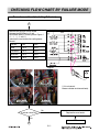
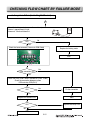
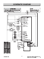
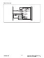
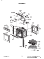
1
삼
정
흥
판
Internal Use Only
Website http://biz.lgservice.com
30” ELECTRIC CONVECTION
BUILT-IN OVEN
SERVICE MANUAL
MODEL: LWS3081ST
CAUTION
BEFORE SERVICING THE UNIT, READ THE SAFETY PRECAUTIONS IN THIS MANUAL.
August, 2008
Printed in Korea
P/NO : MFL37118305
1
FORWARD
This LG Service Manual, “30” Electric Built-in Oven”, provides the technician with information on
the operation and service of the Electric Built-in Oven. It is to be used as a training Service
Manual. For specific information on the model being serviced, refer to the “Owner’s Manual” or
“Tech Sheet” provided with the electric oven.
SAFETY PRECAUTIONS
• Repairs of the appliance should be carried out by a licensed technician only. Incorrect repairs
may result in dangerous situations. If you need repairs, contact an LG Service Center or your
dealer.
• If the power cord is defective, it must be replaced by a qualified service agent with a UL listed
range cord.
• Electrical leads and cables should not be allowed to touch the oven.
• Rating plate is located on the bracket below the control panel.
• The power supply of the appliance should be turned off when it is being repaired.
WARNING
• DISCONNECT power supply cord from the outlet before servicing.
• Replace all panels and parts before operating.
• RECONNECT all grounding devices.
- Failure to do so can result in severe personal injury, death or electrical shock.
• DO NOT Touch when the oven operates.
- The interior parts will be very hot.
LG Electronics assumes no responsibility for any repairs made
on our products by anyone other than Authorized Service Technicians.
TABLE OF CONTENTS
(PAGE)
GENERAL- - - - - - - - - - - - - - - - - - - - - - - - - - - - - - - - - - - - - - - - - - - - - - - - - - - - - - - - - - - - - - - - - - - - - - - - - - - - - - - - - - - - - - - - - - - - 1-1 ~ 1-6
• Read all instructions before use - - - - - - - - - - - - - - - - - - - - - - - - - - - - - - - - - - - - - - - - - - - - - - - - - - - - - - - - - - - - - - - - - - - - - - - - - - - - - - - - - 1-1 ~ 1-4
• Model & Serial number label and tech sheet locations - - - - - - - - - - - - - - - - - - - - - - - - - - - - - - - - - - - - - - - - - - - - - - - - - - - - - - - - - - - 1-5
• Specifications - - - - - - - - - - - - - - - - - - - - - - - - - - - - - - - - - - - - - - - - - - - - - - - - - - - - - - - - - - - - - - - - - - - - - - - - - - - - - - - - - - - - - - - - - - - - - - - - - - - - - - - - - - - - - - - - - - 1-6
USING YOUR OVEN - - - - - - - - - - - - - - - - - - - - - - - - - - - - - - - - - - - - - - - - - - - - - - - - - - - - - - - - - - - - - - - - - - - - - - - - - - - - 2-1 ~ 2-5
• General information - - - - - - - - - - - - - - - - - - - - - - - - - - - - - - - - - - - - - - - - - - - - - - - - - - - - - - - - - - - - - - - - - - - - - - - - - - - - - - - - - - - - - - - - - - - - - - - - - - - - - - - - - 2-1
• Control panel feature - - - - - - - - - - - - - - - - - - - - - - - - - - - - - - - - - - - - - - - - - - - - - - - - - - - - - - - - - - - - - - - - - - - - - - - - - - - - - - - - - - - - - - - - - - - - - - - - 2-2 ~ 2-5
- Setting the initial control
- Start, clear/off
- Oven light
- Timer
- Control lockout
- Set up: 8 different category
1) Language selection
2) Temperature selection unit
3) Display brightness
4) Sound volume Loud/Normal/Mute
5) Convection auto conversion
6) Temperature adjustment
7) Clock time
8) Reset
- Bake
- Timed cook, Delayed timed cook
- Broil
- Roast
- Convection bake
- Crisp convection
- Convection roast
- Recipe bank
- Proof/Warm
- Healthier roast
- My menu
- Option
- Self clean
DISASSEMBLY INSTRUCTIONS - - - - - - - - - - - - - - - - - - - - - - - - - - - - - - - - - - - - - - - - - - - - - - - - - - - - - - - - - - 3-1 ~ 3-3
• Component Locations- - - - - - - - - - - - - - - - - - - - - - - - - - - - - - - - - - - - - - - - - - - - - - - - - - - - - - - - - - - - - - - - - - - - - - - - - - - - - - - - - - - - - - - - 3-1
DISASSEMBLY INSTRUCTIONS - - - - - - - - - - - - - - - - - - - - - - - - - - - - - - - - - - - - - - - - - - - - - - - - - - - - - - - - - - - 3-2 ~ 3-3
• Replacing the control panel and related components - - - - - - - - - - - - - - - - - - - - - - - - - - - - - - - - - - - - - - - - - - - - - - - - - - - - - - - - - 3-2~3-3
- Removing the Low Voltage Transformer (controller)- - - - - - - - - - - - - - - - - - - - - - - - - - - - - - - - - - - - - - - - - - - - - - - - - - - - - - - - - - - - - - 3-2
- Removing the Relay PCB - - - - - - - - - - - - - - - - - - - - - - - - - - - - - - - - - - - - - - - - - - - - - - - - - - - - - - - - - - - - - - - - - - - - - - - - - - - - - - - - - - - - - - - - - - - - - - - - - 3-3
- Removing the door lock assembly- - - - - - - - - - - - - - - - - - - - - - - - - - - - - - - - - - - - - - - - - - - - - - - - - - - - - - - - - - - - - - - - - - - - - - - - - - - - - - - - - - - - - - 3-3
- Removing the Low Voltage Transformer (halogen lamp) - - - - - - - - - - - - - - - - - - - - - - - - - - - - - - - - - - - - - - - - - - - - - - - - - - - - - - - - 3-3
- Removing the Serge filter - - - - - - - - - - - - - - - - - - - - - - - - - - - - - - - - - - - - - - - - - - - - - - - - - - - - - - - - - - - - - - - - - - - - - - - - - - - - - - - - - - - - - - - - - - - - - - - - - 3-3
DISASSEMBLY INSTRUCTIONS- - - - - - - - - - - - - - - - - - - - - - - - - - - - - - - - - - - - - - - - - - - - - - - - - - - - - - - - - - - - 3-4 ~ 3-5
• Replacing oven cavity components - - - - - - - - - - - - - - - - - - - - - - - - - - - - - - - - - - - - - - - - - - - - - - - - - - - - - - - - - - - - - - - - - - - - - - - - - - - - - - - 3-4 ~ 3-5
- Removing the Broil element - - - - - - - - - - - - - - - - - - - - - - - - - - - - - - - - - - - - - - - - - - - - - - - - - - - - - - - - - - - - - - - - - - - - - - - - - - - - - - - - - - - - - - - - - - - - - - 3-4
- Removing the Convection element - - - - - - - - - - - - - - - - - - - - - - - - - - - - - - - - - - - - - - - - - - - - - - - - - - - - - - - - - - - - - - - - - - - - - - - - - - - - - - - - - - - - - 3-4
- Removing the Blade fan - - - - - - - - - - - - - - - - - - - - - - - - - - - - - - - - - - - - - - - - - - - - - - - - - - - - - - - - - - - - - - - - - - - - - - - - - - - - - - - - - - - - - - - - - - - - - - - - - - - 3-5
- Removing the Halogen lamp & socket assembly - - - - - - - - - - - - - - - - - - - - - - - - - - - - - - - - - - - - - - - - - - - - - - - - - - - - - - - - - - - - - - - - - - 3-5
• Replacing other electrical components.- - - - - - - - - - - - - - - - - - - - - - - - - - - - - - - - - - - - - - - - - - - - - - - - - - - - - - - - - - - - - - - - - - - - - - - - - - 3-6 ~ 3-9
- Removing the Vent motor - - - - - - - - - - - - - - - - - - - - - - - - - - - - - - - - - - - - - - - - - - - - - - - - - - - - - - - - - - - - - - - - - - - - - - - - - - - - - - - - - - - - - - - - - - - - - - - - - 3-6
- Removing the Thermal limiter - - - - - - - - - - - - - - - - - - - - - - - - - - - - - - - - - - - - - - - - - - - - - - - - - - - - - - - - - - - - - - - - - - - - - - - - - - - - - - - - - - - - - - - - - - - 3-7
- Removing the Door switch - - - - - - - - - - - - - - - - - - - - - - - - - - - - - - - - - - - - - - - - - - - - - - - - - - - - - - - - - - - - - - - - - - - - - - - - - - - - - - - - - - - - - - - - - - - - - - - 3-7
- Removing the Thermal limiter (Double Line Break) - - - - - - - - - - - - - - - - - - - - - - - - - - - - - - - - - - - - - - - - - - - - - - - - - - - - - - - - - - - - - - - 3-8
- Removing the Convection motor assembly - - - - - - - - - - - - - - - - - - - - - - - - - - - - - - - - - - - - - - - - - - - - - - - - - - - - - - - - - - - - - - - - - - - - - - - - - 3-8
- Removing the Hidden bake element - - - - - - - - - - - - - - - - - - - - - - - - - - - - - - - - - - - - - - - - - - - - - - - - - - - - - - - - - - - - - - - - - - - - - - - - - - - 3-8 ~ 3-9
DISASSEMBLY INSTRUCTIONS - - - - - - - - - - - - - - - - - - - - - - - - - - - - - - - - - - - - - - - - - - - - - - - - - - - - - - - - 3-10 ~ 3-13
• Removing & Reinstalling the lift-off oven door - - - - - - - - - - - - - - - - - - - - - - - - - - - - - - - - - - - - - - - - - - - - - - - - - - - - - - - - - - - - - - - - - - - - - - - 3-10
• Removing the oven door handle & glass- - - - - - - - - - - - - - - - - - - - - - - - - - - - - - - - - - - - - - - - - - - - - - - - - - - - - - - - - - - - - - - - - - - - - 3-11 ~ 3-12
• Removing the oven door gasket- - - - - - - - - - - - - - - - - - - - - - - - - - - - - - - - - - - - - - - - - - - - - - - - - - - - - - - - - - - - - - - - - - - - - - - - - - - - - - - - - - - - - - - - - - 3-13
COMPONENT TEST - - - - - - - - - - - - - - - - - - - - - - - - - - - - - - - - - - - - - - - - - - - - - - - - - - - - - - - - - - - - - - - - - - - - - - - - - - - - - 4-1 ~ 4-4
• Convection motor- - - - - - - - - - - - - - - - - - - - - - - - - - - - - - - - - - - - - - - - - - - - - - - - - - - - - - - - - - - - - - - - - - - - - - - - - - - - - - - - - - - - - - - - - - - - - - - - - - - - - - - - - - - - - 4-1
• Door locking motor- - - - - - - - - - - - - - - - - - - - - - - - - - - - - - - - - - - - - - - - - - - - - - - - - - - - - - - - - - - - - - - - - - - - - - - - - - - - - - - - - - - - - - - - - - - - - - - - - - - - - - - - - - - 4-2
• Door locking micro switch - - - - - - - - - - - - - - - - - - - - - - - - - - - - - - - - - - - - - - - - - - - - - - - - - - - - - - - - - - - - - - - - - - - - - - - - - - - - - - - - - - - - - - - - - - - - - - - - - 4-2
• Low Voltage Transformer - Controller - - - - - - - - - - - - - - - - - - - - - - - - - - - - - - - - - - - - - - - - - - - - - - - - - - - - - - - - - - - - - - - - - - - - - - - - - - - - - - - - 4-2
• Low Voltage Transformer - Halogen lamp - - - - - - - - - - - - - - - - - - - - - - - - - - - - - - - - - - - - - - - - - - - - - - - - - - - - - - - - - - - - - - - - - - - - - - - - - - 4-2
• Oven Thermistor - - - - - - - - - - - - - - - - - - - - - - - - - - - - - - - - - - - - - - - - - - - - - - - - - - - - - - - - - - - - - - - - - - - - - - - - - - - - - - - - - - - - - - - - - - - - - - - - - - - - - - - - - - - - - - 4-3
• Door switch - - - - - - - - - - - - - - - - - - - - - - - - - - - - - - - - - - - - - - - - - - - - - - - - - - - - - - - - - - - - - - - - - - - - - - - - - - - - - - - - - - - - - - - - - - - - - - - - - - - - - - - - - - - - - - - - - - - - - 4-3
• Oven lamp - - - - - - - - - - - - - - - - - - - - - - - - - - - - - - - - - - - - - - - - - - - - - - - - - - - - - - - - - - - - - - - - - - - - - - - - - - - - - - - - - - - - - - - - - - - - - - - - - - - - - - - - - - - - - - - - - - - - - - 4-3
• Broil Element - - - - - - - - - - - - - - - - - - - - - - - - - - - - - - - - - - - - - - - - - - - - - - - - - - - - - - - - - - - - - - - - - - - - - - - - - - - - - - - - - - - - - - - - - - - - - - - - - - - - - - - - - - - - - - - - - - - 4-4
• Bake Element - - - - - - - - - - - - - - - - - - - - - - - - - - - - - - - - - - - - - - - - - - - - - - - - - - - - - - - - - - - - - - - - - - - - - - - - - - - - - - - - - - - - - - - - - - - - - - - - - - - - - - - - - - - - - - - - - - 4-4
• Convection element - - - - - - - - - - - - - - - - - - - - - - - - - - - - - - - - - - - - - - - - - - - - - - - - - - - - - - - - - - - - - - - - - - - - - - - - - - - - - - - - - - - - - - - - - - - - - - - - - - - - - - - - - 4-4
• Vent motor - - - - - - - - - - - - - - - - - - - - - - - - - - - - - - - - - - - - - - - - - - - - - - - - - - - - - - - - - - - - - - - - - - - - - - - - - - - - - - - - - - - - - - - - - - - - - - - - - - - - - - - - - - - - - - - - - - - - - - 4-4
DIAGNOSIS THROUGH SCHEMATIC - - - - - - - - - - - - - - - - - - - - - - - - - - - - - - - - - - - - - - - - - - - - - - - - - - - - - - - - - - - 5-1
HOW TO ENTER THE TEST MODE - - - - - - - - - - - - - - - - - - - - - - - - - - - - - - - - - - - - - - - - - - - - - - - - - - - - - - - - - - - - - - 5-2
SAFETY CAUTION & ERROR CODE SUMMARY - - - - - - - - - - - - - - - - - - - - - - - - - - - - - - - - - - - - - - - - - - - 5-3
CHECKING FLOW CHART BY FAILURE MODE - - - - - - - - - - - - - - - - - - - - - - - - - - - - - - - - - - 5-3 ~ 5-18
• Dead - - - - - - - - - - - - - - - - - - - - - - - - - - - - - - - - - - - - - - - - - - - - - - - - - - - - - - - - - - - - - - - - - - - - - - - - - - - - - - - - - - - - - - - - - - - - - - - - - - - - - - - - - - - - - - - - - - - - - - - 5-4 ~ 5-8
• Oven does not heat (including F-9 error) - - - - - - - - - - - - - - - - - - - - - - - - - - - - - - - - - - - - - - - - - - - - - - - - - - - - - - - - - - - - - - - - - - - - - 5-9 ~ 5-12
• Not operating Key (including F-3 error)- - - - - - - - - - - - - - - - - - - - - - - - - - - - - - - - - - - - - - - - - - - - - - - - - - - - - - - - - - - - - - - - - - - - - - - - - - - - - - - - 5-13
• Lock system failure (including F-10 error)- - - - - - - - - - - - - - - - - - - - - - - - - - - - - - - - - - - - - - - - - - - - - - - - - - - - - - - - - - - - - - - - - - - 5-14 ~ 5-15
• Oven Thermistor failed (including F-1, F-2 error)- - - - - - - - - - - - - - - - - - - - - - - - - - - - - - - - - - - - - - - - - - - - - - - - - - - - - - - - - - - - - - - - - - - 5-16
• Oven too hot (including F-6 error)- - - - - - - - - - - - - - - - - - - - - - - - - - - - - - - - - - - - - - - - - - - - - - - - - - - - - - - - - - - - - - - - - - - - - - - - - - - - - - - - - - - - - - - 5-17
• Communication error → F-10 error - - - - - - - - - - - - - - - - - - - - - - - - - - - - - - - - - - - - - - - - - - - - - - - - - - - - - - - - - - - - - - - - - - - - - - - - - - - - - - - - - - - - - 5-18
SCHEMATIC DIAGRAM - - - - - - - - - - - - - - - - - - - - - - - - - - - - - - - - - - - - - - - - - - - - - - - - - - - - - - - - - - - - - - - - - - - - - - - - - - - - - - - 6-1
• Strip circuits - - - - - - - - - - - - - - - - - - - - - - - - - - - - - - - - - - - - - - - - - - - - - - - - - - - - - - - - - - - - - - - - - - - - - - - - - - - - - - - - - - - - - - - - - - 6-2 ~ 6-5
EXPLODED VIEW - - - - - - - - - - - - - - - - - - - - - - - - - - - - - - - - - - - - - - - - - - - - - - - - - - - - - - - - - - - - - - - - - - - - - - - - - - - - - - - 7-1 ~ 7-6
REPLACEMENT PARTS LIST - - - - - - - - - - - - - - - - - - - - - - - - - - - - - - - - - - - - - - - - - - - - - - - - - - - - - - - - - - - - - - 8-1 ~ 8-3
GENERAL
READ ALL INSTRUCTIONS BEFORE USE
Read and follow all instructions before using your oven to prevent the risk of fire, electric shock, injury to person, or
damage when using the range. This guide don’t cover all possible conditions that may occur. For further assistance
contact your service agent or manufacturer.
This is the safety alert symbol. This symbol alerts you to potential hazards that can kill or hunt you
and others. All safety messages will follow the safety alert symbol and either the word “WARNING”
or “CAUTION”. These word means :
WARNING
This symbol will alert you to hazards or unsafe practices which could cause
serious bodily harm or death.
CAUTION
This symbol will alert you to hazards or unsafe practices which could cause
bodily injury or property damage.
WARNING
• NEVER use your appliance for warming or heating the room.
• DO NOT use water on grease fires.
- Turn off the oven to avoid spreading the flames. Smother the fire by closing the oven door or use dry chemical,
baking soda, or foam-type extinguishers.
• Use only dry pot holders.
- Moist or damp pot holders on hot surfaces may result in burns from steam. Do not let the pot holder touch hot
heating elements. Do not use a towel or other bulky cloth.
• Storage in or on appliance.
- Flammable materials should not be stored in an oven or near surface elements.
• Wear proper apparel.
- Loose-fitting or hanging garments should never be worn while using the appliance.
• DO NOT place aluminum foil directly on the oven bottom.
• Children should be kept away from the oven.
- Accessible parts may become hot when the broil is use.
• DISCONNECT power supply cord from the outlet before servicing.
• Replace all panels and parts before operating.
• RECONNECT all grounding devices.
- Failure to do so can result in severe personal injury, death or electrical shock.
• DO NOT Touch when the oven operates.
- The interior parts will be very hot.
• ELECTRIC SHOCK HAZARD
- Unit must be disconnected from electrical outlet when making repairs, replacements, adjustments. Replace all
panels before operating oven. Failure to do so can result in death or electrical shock.
CAUTION
• DO NOT leave children alone.
- Children should not be left alone or unattended in area where appliance is in use.
- Children should never be allowed to sit or stand on any part of the appliance.
• DO NOT leave small children unattended near the appliance.
- During the self-cleaning cycle, the outside of the oven can become very hot to touch.
• Be careful when you work on the electric oven handling the sheet metal part.
- Sharp edge may be present and you can cut yourself.
• Be careful not to bend the fan blade.
• The door is very heavy. Be careful when removing and lifting door. Do not lift the
door by the handle.
1-1
GENERAL
READ ALL INSTRUCTIONS BEFORE USE
SAFETY PRECAUTIONS
• Be certain all packing materials are removed
from the appliance before operating.
Keep plastics, clothes, and paper away from
parts of the appliance that may become hot.
• DO NOT force the door open.
This can damage the automatic door locking
system. Use care when opening the oven door
after the self-cleaning cycle. Stand to the side of
the oven when opening the door to allow hot air
or steam to escape. The oven may still be
VERY HOT.
• DO NOT use a steel-wool pad.
It will SCRATCH the surface.
• DO NOT use harsh etching, abrasive
cleaners or sharp metal scrapers to clean
the oven door glass since they can scratch
the surface.
It may result in shattering of the glass.
• Be careful when removing and lifting the door.
• DO NOT lift the door by the handle.
The door is very heavy.
• DO NOT step or sit on oven door.
Be sure to follow proper installation instructions.
• Be certain your appliance is properly installed
and grounded by a qualified technician.
• Do not repair or replace any part of the
appliance unless specifically recommended in
the manual.
• All other servicing should be referred to a
qualified technician.
• Always disconnect power to appliance before
servicing by unplugging, removing the fuse or
switching off the circuit breaker.
• DO NOT TOUCH HEATING ELEMENTS OR
INTERIOR SURFACES OF OVEN.
Heating elements may be hot even though they
are dark in color. Interior surfaces of an oven
become hot enough to cause burns. During and
after use, do not touch or let clothing or other
flammable materials contact heating elements
or interior surfaces of oven until they have had
sufficient time to cool. Other surfaces of the
appliance may become hot enough to cause
burns. Among these surfaces are oven vent
openings and surfaces near these openings,
oven doors, and windows of oven doors.
• Use Care When Opening Door.
Let hot air or steam escape before you remove
or replace food in the oven
• Do Not Heat Unopened Food Containers.
Build-up of pressure may cause container to
burst and result in injury.
• Keep Oven Vent
Ducts Unobstructed.
The oven vent could
become hot during
oven use. Never block
this vent and never
Metal bottom
place plastic or heattrim (Vent)
sensitive items on or
near the vent.
NOTE:
For proper operation vent trim must be installed.
ELECTRICAL SAFETY
• Protective Liners. Do not use aluminum foil or
any other material to line the oven bottoms.
Improper installation of these liners may result
in a risk of electric shock or fire.
• Do Not allow aluminum foil or meat probe to
contact heating elements.
WARNING
Aluminum foil
• DO NOT place aluminum foil directly
on the oven bottom.
1-2
GENERAL
READ ALL INSTRUCTIONS BEFORE USE
• Before replacing your oven light bulb,
switch off the electrical power to the oven at
the main fuse or circuit breaker panel.
Failure to do so can result in severe personal
injury, death, or electrical shock.
• DO NOT line the oven walls, racks, bottom,
or any other part of the oven with aluminum
foil or any other material.
Doing so will disrupt heat distribution, produce
poor baking results and cause permanent
damage to the oven interior (aluminum foil will
melt to the interior surface of the oven.)
CHILD SAFETY
WARNING
• Children should be kept away
from the oven.
• Accessory parts will become hot
when the broiler is in use.
CAUTION
SAFETY DURING USE
• Children should not be left alone
or unattended in area where
appliance is in use. Children
should never be allowed to sit or
stand on any part of the
appliance.
• Oven Racks. Always place oven racks in
desired position while oven is cool.
• Always use pot holders or oven mitts when
removing food from the oven.
You can be burned because cookware and
plates will be hot.
• Use caution with the TIMED BAKE or
DELAYED TIMED BAKE features. Use the
automatic timer when cooking cured or
frozen meats and most fruits and
vegetables. Foods that can easily spoil,
such as milk, eggs, fish, meat or poultry,
should be chilled in the refrigerator first.
Even when chilled, they should not stand in
the oven for more than 1 hour before
cooking begins, and should be removed
promptly when cooking is completed.
Eating spoiled food can result in sickness from
food poisoning.
• Should an oven fire occur, leave the oven
door closed and turn the oven off. If the fire
continues, throw baking soda on the fire or
use a fire extinguisher.
• DO NOT put water or flour on the fire.
Flour may be explosive and water can cause a
grease fire to spread and cause personal injury.
• DO NOT use the broiler pan without the grid.
DO NOT cover the grid with aluminum foil.
CAUTION
• DO NOT leave small children
unattended near the appliance.
During the self-cleaning cycle, the
outside of the oven can become very hot
to the touch.
1-3
GENERAL
READ ALL INSTRUCTIONS BEFORE USE
SAFETY WHEN CLEANING
• Important Instruction. In the event the self
clean error code F is displayed, and error
melody sounds, the oven is malfunctioning in
the self clean mode. Switch off the electrical
power to the main fuse or breaker and have
serviced by a qualified technician.
• Make sure oven lights are cool before
cleaning.
• DO NOT block the oven vent during
operation.
This can damage the electric parts of the oven.
Air must be able to move freely. The metal
bottom trim (vent) should be properly
assembled on the front bottom of oven before
installing the oven door.
• Do Not Clean Door Gasket. The door gasket is
essential for a good seal. Care should be taken
not to rub, damage, or move the gasket.
• Do Not Use Oven Cleaners. No commercial
oven cleaner or oven liner protective coating of
any kind should be used in or around any part
of the oven.
• Before self cleaning the oven. Remove broiler
pan, all oven racks, meat probe and any other
utensils from the oven cavity.
• Never keep pet birds in the kitchen. The
health of birds is extremely sensitive to the
fumes released during an oven self-clean cycle.
Fumes may be harmful or fatal to birds. Move
birds to well-ventilated room.
Metal bottom trim
(Vent)
1-4
GENERAL
MODEL & SERIAL NUMBER LABEL AND
TECH SHEET LOCATION
The Model/Serial Number label and Tech Sheet locations are shown below.
Model & Serial
Number Location
Tech Sheet Location
1-5
GENERAL
SPECIFICATIONS
Product Specification List
No
Items
Specifications
Remarks
1
Model name
LWS3081ST
2
Rating power source
240 V~ 60 Hz
3
Heat source
Sheath heater & Carbon heater
4
Max power
4.1 KW
5
Max input current
17.3 A
6
Rating power consumption
Bake
2,500W / 10.4A
& Rating input current
Broil
4,000W / 16.7A
Convection
2,500W /10.4A
Lamp
12V/10W/0.8A
Front ceiling area
Lamp
(12V/10W/0.8A×2)
Left & right sides
Cooling motor
120V/41W/0.34A
Convection motor
120V/42W/0.65A
Locking motor
120V/3.5W/0.03A
Built-in Single wall oven
North American market
Single phase & 4-wires
120/208V : 3.0 KW
7
Efficiency
Higher than 80%
8
Control style
Touch screen, glass touch & Micom
9
Display
White LCD
Liquid Crystal Display
10
Power control range
170~550˚F (77~288˚C)
At bake mode
11
Capacity (Overall, W×H×D)
4.7 cu.ft
(622×449×474 )
24 1/2×17 11/16×18 5/8
12
Capacity (Usable)
3.2 cu.ft
(601×345×436 )
23 5/8×13 9/16×17 3/16
13
Cut out size (W×H×D)
724×735×596
28 1/2×28 15/16×23 1/2
14
Unit Dimension
755×745×619
29 3/4×29 5/16×24 3/8
15
Net Weight
71 Kg
154 lbs
16
Packing size
838×864×762
33×34×30
17
Packing weight
81 Kg
187 lbs
18
Stack height
3 levels
1-6
USING YOUR OVEN
GENERAL INFORMATION
Cooking Guide
Refer to the owners manual for recommendations
of times and temperatures. Times, rack position,
and temperatures may vary depending on
conditions and food type. For best results, always
check food at minimum time. When roasting,
choose rack position based on size of food item.
Rating Label
Model numbers are recorded on the rating label.
Rating label is located on the lower left bottom
area of the controller. It can be seen by opening
the door. Before ordering parts, write down the
correct model and serial number from rating
label. This avoids incorrect shipments and
delays. Please refer to parts reference material
when ordering replacement parts.
Functional Operation
Bake Mode
Top and hidden bottom elements operate during
bake. Bake can be used to cook foods which are
normally baked. Oven must be preheated.
Convection fan and heater operates during the
Preheat cycle of Bake mode.
Broil Mode
Top element operates during broil. Broil can be
used to cook foods which are normally broiled.
Preheating is not required when using broil. All
foods should be turned at least once except fish,
which does not need to be turned.
Convection Bake / Roast Mode
Upper element, lower element, Rear element and
fan operate during convection bake. Convection
bake should be used for cooking casseroles and
roasting meats. Oven should be preheated for
best results when using convection bake. Pans
do not need to be staggered. Cooks
approximately 25% quicker than bake.
Broil element
Convection
element
Bake element
2-1
USING YOUR OVEN
CONTROL PANEL FEATURES
READ THE INSTRUCTIONS CAREFULLY BEFORE USING THE OVEN. For satisfactory use of your
oven, become familiar with the various features and functions of the oven as described below.
1
5
3
4
1. OVEN LIGHT: Use to turn the oven lights on and off.
2. START: Use to start all oven features. Activate the
CONTROL LOCK for 4 seconds holding.
3. TIMER ON/OFF: Use to set or cancel the timer.
4. CLEAR/OFF: Use to stop cooking or cancel the setting of
the oven.
5. Touch Screen: Show the time of day, main menu, and oven
temperature; whether the oven is the bake, broil or selfcleaning mode; and the times set for the timer or automatic
oven operations. The display panel will go into a "sleep"
mode if no activity. Touch the display once to activate and
again to make your selection.
6
7
8
12
13
10
6. Bake: Use to select the normal bake mode.
7. Broil: Use to set the variable broil mode.
8. Roast: Use to select the normal roast mode.
9. Conv. Bake: Use to select the convection bake mode.
10. Crisp Conv.: Use to select the crisp convection mode.
11. Conv. Roast: Use to select the convection roast mode.
12. Recipe Bank: Use to recall the recipe category of gourmet
food.
13. Proof/Warm: Use to proof bread / Use to hold food warm.
14. Healthier Roast: Use to select the healthier roast mode.
15. My Menu: Use to save or recall the favorite 10 cook mode.
16. Set up: Use to change the special settings.
17. Self Clean: Use to select the self-cleaning cycle.
15
NOTE:
• Press CLEAR/OFF pad. Allow the oven to cool for one hour.
Put back into operation.
• If the function error code repeats, disconnect the power
to the oven and call for service.
• If the oven was set for a timed oven operation and a power
failure occurred, the clock and all programmed functions must
be reset.
• The time of day will flash and PF will appear in the display
when there has been a power failure.
00:00:00 11:35 am
Cook & Warm
9
2
14
11
16
17
2-2
USING YOUR OVEN
3) Hour and Min setting
1. SETTING THE INITIAL CONTROL
1) LG logo display 8 seconds. - Initial display
(Power Failure or Reset)
First, Select Language, and set clock time, and
then the oven can be used.
If power failure occurs, the oven will remember
your language selection however you will still
need to set the time of day.
TIMER
TIMER
NUMERIC (Set the
desired time-hour and min)
TIMER
4) When the set time has elapsed, “Timer End” is
displayed. Timer alarm melody will sound every
15 seconds until TIMER is pressed. Press timer
key in order to cancel running timer or clear timer
end alarm. The time less than 1hour is displayed
in min and sec on timer operation.
5. CONTROL LOCKOUT
1) The START key controls the Control Lock
feature. The Control Lock feature automatically
locks most oven controls from being turned ON.
It does not disable the timer and the interior oven
light. The Control Lock feature will cancel the
cooking mode and will lock the oven controls at
any time when you activate this feature.
2) Key Input Process : START (for 4 seconds)
2) Key Function, General Usage While selecting
any function, an appropriate key input sequence
must be followed. In case of an inappropriate
input sequence the key error beeps sound.
Numeric key are used while entering data
(temperature and time) for cooking.
2. START, CLEAR/OFF
Lock melody will sound.
1) START key to start oven
2) CLEAR/OFF key to cancel a program during
cooking or erase during programming.
3) To unlock the control, press START (for 4 seconds)
Unlock melody will sound.
3. OVEN LIGHT
6. SET UP (8 DIFFERENT CATEGORIES)
1) Requirement: The Oven Light is used to turn on
or off the oven light.
2) Key Input Process: Oven Light-ON/OFF toggle
operation.
If the Oven Light is on by pressing oven light key,
the light is on even if the door is closed. Oven
light key can be operated while door opens.
3) Exception: Oven light will not operate during a
self clean cycle. Once self clean is
complete the oven light will not
operate until oven cools down.
1) Language Selection
1. Requirement: The scroll display can be shown
either in English/Spanish/French.
2. Key Input Process
Set Up
Select language
3. CLEAR to reject the change.
2) Temperature Selection unit
1. Requirement: The oven control can be
programmed to display temperatures in
Fahrenheit or Centigrade. The oven has been
preset at the factory to display in Fahrenheit.
2. Key Input Process
4. TIMER
1) Requirement: The timer works like an alarm clock
that will continuously beep until turned off. The
oven can fully operate during the use of the timer.
Set Up
Select Temp.Unit
- Setting Limit : 11Hour : 59Min
3. CLEAR to reject the change.
2) Min and Sec Setting;
TIMER
NUMERIC (Set the
desired time-min and sec)
OK
TIMER
2-3
OK
USING YOUR OVEN
3) Display brightness
1. Requirement: LCD Display Brightness
adjustment
2. Key Input Process
Set Up
Select Brightness
7) Clock Time
1. Requirement: The clock key is used to set the
clock in idle mode. The clock can be set to 12
or 24 hour format. am and pm can be set in 12
hours.When the oven is initially plugged in, or
when the power supply to the oven is
interrupted, the clock time is saved in ROM.
2. Key Input Process
OK
3. CLEAR to reject the change.
4) Sound Volume Loud/Normal/Mute
1. Requirement: When want to reduce or
increase the volume.
2. Key Input Process
Set Up
Select Volume
Set Up
Select
hours
set clock time
select am, pm
OK
OK
3. CLEAR to cancel the clock setting.
8) Reset
1. Requirement: Setting Value will be default
value.
2. Key Input Process
3. CLEAR to reject the change.
4. Exception : Error Alarm, Preheat Alarm, Timer
End Alarm – If Mute, Normal Beep Sounds.
5) Convection Auto Conversion
1. Requirement: When using convection, Auto
conversion will automatically convert an
entered regular baking temperatures to
convection baking temperatures.
2. Key Input Process
Set Up
Select Yes, No
OK
3. CLEAR to reject the change.
7. BAKE
Set Up
Select mode
OK
BAKE
3. CLEAR to reject the change.
6) Temperature Adjustment
1. To change the oven temperature during use
follow the steps below.
BAKE
BROIL
2. Key Input Process
Adjust Temperature
START
8. TIMED COOK, DELAYED TIMED COOK
Fahrenheit : (-)35 ~ (+)35
Centigrade : (-)19 ~ (+)19
Set Up
Desired Temperature
START
OK
Desired
Temperature
START
Desired
Temperature
START
Cook &
warm
3. CLEAR to reject the change.
* Note: This adjustment is available for Bake,
Roast, Convection Bake, Roast, Crisp Conv.
Healthier Roast. Temperature Adjustment can be
confirmed by measuring real Oven Cavity
Temperature.
START
TIME
Desired
start time
START
Cook &
warm
2-4
USING YOUR OVEN
9. BROIL
16. HEALTHIER ROAST
Healthier
Roast
Desired Broil
Full / Center
Broil
Desired Temp
High / Med / Low
Desired
Temperature
START
Desired
Temperature
START
17. My MENU
11. CONVECTION BAKE
Conv.
Bake
Desired
Temperature
Desired
Temperature
START
START
13. CONVECTION ROAST
Conv.
Roast
Desired
Temperature
Select cook
menu
Desired
temp
Option
Enter
My menu
Select
My menu
START
18. OPTION
START
Option
14. RECIPE BANK
Recipe
create
My Menu
12. CRISP CONVECTION
Crisp
Conv.
START
* Note: The meat probe must be used in this
feature.
(refer to the HEALTHIER ROASTING CHART.)
10. ROAST
ROAST
Selected food
category
Temp Cook time
Start time
OK
19. SELF CLEAN
Select
Recipes
Corresponding
menu
Option
START
Select
clean level
: Light → 2Hours
: Normal →
3Hours
START
15. PROOF/WARM
Proof
Desired
Cook time
START
Warm
Selected
Temp.
START
Start
Time
2-5
Desired Start
time
START
DISASSEMBLY INSTRUCTIONS
This section instructs you on how to service each component inside the oven. The components and their
locations are shown below.
COMPONENT LOCATIONS
Main PCB
Display PCB
Low Voltage Transformer
Side Key PCB
Upper Oven Light
Upper Door Latch
Assembly
Oven Sensor
Upper Door Switch
Convection Motor
Convection Heater
Hinge Hanger
Bake Heater
3-1
DISASSEMBLY INSTRUCTIONS
REPLACING THE CONTROL PANEL AND RELATED COMPONENTS
6. Disconnect the 8EA connector from PCB assembly
(CN01, CN02, CN03, CN04, CN08, CN11) and
separate control panel carefully.
WARNING
• ELECTRIC SHOCK HAZARD
- Unit must be disconnected from electrical
outlet when making repairs, replacements,
adjustments. Replace all panels before
operating oven. Failure to do so can result
in death or electrical shock.
CN03
CN03
CN02
CN02
CN11
CN11
CN01
CN01
CN01
CN08
CN08
CAUTION
• Be careful when you work on the
electric oven handling the sheet
metal part.
CN04
CN04
CN04
7. You can see the interior of electric parts chamber.
1. Turn off the electrical supply going to the oven.
2. Open the door assembly.
3. Remove the 3 screws from below the control
panel.
8. To remove the following components follow the
sequence below.
Controller LVT, Relay PCB, Door lock motor,
Halogen lamp LVT, Surge filter can be serviced
without removing the oven.
4.Close the door assembly.
5. Lift the control panel off from the guide hooks
and top trim. Tilt the control panel down.
Hinge panel into slots on main body and let
control panel rest.
Controller
Controller
LVT
LVT
LVT
Relay
Relay
Relay
PCB
PCB
PCB
Halogen
lamp
Halogen lamp
lamp
Door lock
lock Halogen
Door
LVT
LVT
LVT
motor
motor
motor
1) To remove the PCB Low voltage transformer.
Remove the 1 screw.
Guide
Guide
Guide hole
hole
hole
Hook
Hook
Hook
3-2
DISASSEMBLY INSTRUCTIONS
2) To remove the Relay PCB, Remove 1 screw
and slide relay PCB out.
Disconnect the 7EA connector from PCB
assembly(CN01, CN02, WH, WH, VI, YL,
RY19) and separate Relay PCB assembly.
TO UNLOCK THE OVEN DOOR MANUALLY
In case of need, the oven door could be unlocked
manually for the service. Follow the steps below.
Unlocking status
Locking status
Cam
RY19
RY19
1. Disconnect oven from the power source.
2. Using a L shaped object
(close hanger) insert it
into the gap between the
door and the control
panel. Grasp the hook
on the motor and pull towards the left. Be
careful not to damage the oven.
3. While holding the door
latch in the Unlocked
position you can now
open the door.
YL
YL
VI
VI
VI
WH
WH
WH
WH
WH
WH
CN02
CN02
CN02
CN01
CN01
CN01
Unlocking tool Door
3) To remove the Door lock assembly, Open the door,
and remove the 2 screws located on the front grill.
Remove the 2 connectors.
Hook
Note: Refer to the service
manual for proper
replacement of the
door lock motor.
4) To remove the Halogen lamp, remove the
1screw.
Disconnect the 5 connections.
DOOR LOCKING MECHANISM
The door lock assembly is located on top of the
oven. The structural elements are as below.
Hook
Motor
5) To remove the Surge filter, remove the
controller LVT and then remove the 1screws
located back plate.
Disconnect the 2 connections.
Unlock
Lock
Micro Switch
The door lock is controlled by the PCB and is
activated when the oven is put into a self clean
cycle. The oven will remain locked after a self
clean until the temperature fall below 500°F/260°C.
If there is a failure of this motor the following steps
can be followed to unlock the door manually.
3-3
DISASSEMBLY INSTRUCTIONS
REPLACING OVEN CAVITY COMPONENTS
1) To remove the broil element:
a. Remove the 4 screws from the front and rear
brackets.
WARNING
• ELECTRIC SHOCK HAZARD
- Unit must be disconnected from electrical
outlet when making repairs, replacements,
adjustments. Replace all panels before
operating oven. Failure to do so can result
in death or electrical shock.
CAUTION
• Be careful when you work on the
electric oven handling the sheet
metal part.
b. Pull the element forward so that you can
access the terminals and disconnect the wires.
1. Turn off the electrical supply going to the oven.
2. Remove the door assembly.
3. To remove the following components follow the
sequence below.
Broil element, Convection element, Fan blade,
Oven thermistor, Halogen lamp can be serviced
without removing the oven.
2) To remove the convection element:
a. Remove the 4 screws on the convection fan
cover.
Broil
elements
Broil
Broil elements
elements
Convection
Convection
Convection
Convection
elements
elements
elements
Oven
Oven
Thermistor
Thermistor
Thermistor
Blade
fan
Blade
Blade fan
fan
Halogen lamp 3EA
3-4
DISASSEMBLY INSTRUCTIONS
b. Remove the 4 convection element screws.
(The convection element is fragile. Care
should be taken to avoid any risk of injury)
4) To remove the halogen lamp & socket assembly
a. There are three halogen lamp & socket
assembly in the oven cavity.
Halogen
Halogen
Halogen lamp
lamp
lamp 3EA
3EA
3EA
c. Pull the element forward so that you can
access the terminals and disconnect the wires.
b. Insert a flat blade
screwdriver into the
guide hole and pull off.
C. Replace the halogen
lamp, then reinstall the
glass cover.
CAUTION
* Note :The above instructions can be used for replacing
any of the halogen bulbs in either oven.
Be careful not to bend the fan blade.
5) To remove oven temperature sensors,
Remove the 2 screws from the temperature
sensor bracket.
Pull the temperature sensor forward and
remove the connector.
3) To remove Blade fan(Convection fan)
a. Remove nut by screwing clockwise.
(be careful fan blade is bent easily)
b. Fan blade can be replaced from inside oven.
Convection
Heater
Fan Motor
Fan Cover Fan Blade
Nut
Bushing
Fan Cover
Scews
(4ea)
Mounting
Scews
(3ea)
Cavity
Washer Inner Outer
3-5
DISASSEMBLY INSTRUCTIONS
REPLACING OTHER ELECTRICAL COMPONENTS
Vent motor
Thermal limiter
WARNING
• ELECTRIC SHOCK HAZARD
- Unit must be disconnected from electrical
outlet when making repairs, replacements,
adjustments. Replace all panels before
operating oven. Failure to do so can result
in death or electrical shock.
CAUTION
• Be careful when you work on the
electric oven handling the sheet
metal part.
Door
Door
Door switch
switch
switch
1. Turn off the electrical supply going to the oven.
2. Pull the oven away from the wall cabinet so that
you can access upper panel.
3. Remove the upper panel, there are 3 total pieces
(13 screws).
Section 1
4. Vent motor, Thermal Limiter, and Door switch can
be serviced here.
1) To remove the vent motor, remove the
2 screws and disconnect connector.
Section 2
Section 3
CONTROLLER PARTS
3-6
DISASSEMBLY INSTRUCTIONS
4) Squeeze tabs on switch and slide through the
front.
Disconnect the wires from terminals.
COOLING FAN (BLOWER)
• Self Clean Mode: The cooling fan can operate
at 2 different speeds based on temperature. If
the temp is above 482°F/250°C the fan will
operate on high. If temp is below 482°F/250°C
the fan will operate on low.
• Normal Cooking Mode: If the oven
temperature reaches 212°F/100°C, the
cooling fan will operate at low speed at a time.
2) To remove thermal disk, remove the 1 screw
and remove the 2 wires.
6. To remove the Thermal limiter, Convection motor,
and Bake Element from the oven, Follow the
steps as follows.
Remove the rear cover.
THERMAL LIMITER
Rear Cover
• To shut down the control power transformer
The upper thermostat is located in front of the
cooling fan. It opens at 356°F/180°C and
closes when the oven temperature cools
below 14°F/-10°C.
The lower thermostat is located next to the
broil element. It opens at 356°F/180°C and
closes when the oven temperature cools
below 14°F/-10°C.
Thermal Limiter
(Double Line Break)
Convection motor
3) To remove door switch, Remove the 1 screw
from the top right panel.
Top
Top
Top right
right
right panel
panel
panel
Bake
element
3-7
DISASSEMBLY INSTRUCTIONS
3) To remove the hidden bake element
a. Remove the Barrier bracket.
1) To Remove Thermal Limiter (Double Line
Break), remove the screw and 2 wire leads.
THERMAL LIMITER
• To shut down the heaters
The thermostat is located at the back of the
oven next to the broil element and wired in
series with the Double Line Break relay.
The oven thermostat opens at 356°F/180°C.
(Reclose Temp. : -31°F/-35°C)
Barrier bracket
2) To remove convection motor assembly
Before removing the convection fan motor, first
follow the steps for removing Convection Heater.
a. Disconnect the 2 wire leads and remove the
3 screws from the motor bracket
b. Disconnect the 2 wire leads, remove the
Bake element cover.
Bake element cover
b. Separate parts of cavity inner between cavity
outer properly.
(refer to the page3-5 About cavity inner
disassembly method)
Convection
Heater
c. Cut the 8 points of flange and remove the
Bake element cover.
Fan Motor
Fan Cover Fan Blade
Nut
Bushing
Fan Cover
Scews
(4ea)
Mounting
Scews
(3ea)
Cavity
Washer Inner Outer
3-8
DISASSEMBLY INSTRUCTIONS
d. Bend the insulator up and remove the
1 screw.
e. Carefully pull the hidden bake element out of
the oven.
f. When replacing the Bake Element cover use
the 5 screws provided.
3-9
DISASSEMBLY INSTRUCTIONS
REMOVING & REINSTALLING THE LIFT-OFF OVEN DOOR
To replace the door:
CAUTION
1. Firmly grasp
both sides of the
door at the top.
The door is very heavy. Be careful
when removing and lifting the door.
Do not lift the door by the handle.
2. With the door at
Hinge arm
the same angle
as the removal
Bottom
position, seat
edge of
the indentation
slot
of the hinge arm
Indentation
into the bottom
edge of the
hinge slot. The notch in the hinge arm must be fully
seated into the bottom of the slot.
To remove the door:
1. Fully open the door.
Lock
Unlock
Slot
2. Pull the hinge locks
down toward (Fig.1)
the door frame, to the
unlocked position.
Hinge
lock
3. Fully open the door. If the door will not fully open, the
indentation is not seated correctly in the bottom edge
of the slot.
<Fig.1>
3. Firmly grasp both sides of the door at the top.
4. Push the hinge locks up
against the front frame of
the oven cavity to the
locked position.
4. Close door to the door
removal position, which is
approximately 5 degrees.
(refer to the Fig.2)
<Fig.2>
5. Close the oven door.
5. Lift door up and out until the hinge arm is clear of the
slot.
3-10
Hinge arm
Hinge lock
DISASSEMBLY INSTRUCTIONS
REMOVING THE OVEN DOOR HANDLE & GLASS
6. To remove the door handle & trim.
a. Remove 2 screws for handle and replace.
b. Slide Door trim up and off.
CAUTION
• Be careful when you work on the
electric oven handling the sheet
metal part.
Handle
screws
1. Remove the oven door from the oven.
(see page 3-11)
2. Place the oven door on a padded work surface
with the front glass facing down.
3. Remove the 4 top door screws.
Door
Door trim
trim
7. To remove the hinge assembly :
1) Remove the 2 lower liner screws (see step 3)
2) Place the door liner assembly on a padded
work surface with the hinge over the edge.
3) Remove the two hinge hanger screws.
444 top
top
top liner
liner
liner screws
screws
screws
Hinge
Hinge
Hinge screws
screws
screws
4. Remove the three bottom screw from the door liner.
4) Remove the 8 screws.
COVER_INNER-2
COVER_INNER-2
COVER_INNER-2
5. Lift the inner assembly off the front glass and set
it aside
3-11
DISASSEMBLY INSTRUCTIONS
5) Lift the COVER_INNER-2 off the door liner.
6) Lift the hinge out of the door liner slot.
To remove the oven door glass assembly:
7) Lift the COVER_INNER-1 off the door liner.
COVER_INNER-1
COVER_INNER-1
8) Lift the inner oven door glass and bracket
assembly out of the door liner.
INNER OVEN DOOR
GLASS & BRACKET
3-12
DISASSEMBLY INSTRUCTIONS
REMOVING THE OVEN DOOR GASKET
1. Remove oven door
2. Pull the oven door gasket clips out of the liner
holes until all of the clips are removed.
3. Pull the ends of the gasket out of the liner holes.
Liner Hole
Door
gasket
Door
gasket
Doorgasket
gasket
Door
Door
gasket
Door
gasket
Door
gasket
REASSEMBLY NOTE: When reinstalling the new
gasket, make sure that all of the clips are seated in
their liner holes, and that the ends of the gasket are
pushed fully into their holes. Use the pointed end of
a pencil to push the gasket ends into the holes.
Gasket
clip
Gasket
clip
Gasket
clip
Gasket
Gasketclip
clip
Gasket
clip
Gasket
clip
3-13
COMPONENT TEST
Before testing any components, perform the following checks:
NOTE:
1. The most common cause for control failure is corrosion on connectors.
Therefore, disconnecting and reconnecting wires will be necessary throughout test procedures
2. If this is a new product check all connections before replacing parts.
1. All test and checks should be made using a VOM or DVM having a range of at least 20,00 ohms or greater.
2. Be sure to check all connections before replacing components. Look for broken or loose wire, failed
terminals or wires not fully seated into the connectors.
3. Resistance checks must be made with power disabled form oven, and with wiring harness or connectors
disconnected.
WARNING
• Disconnect power supply before servicing
• Replace all panels and parts before operating
• Reconnect all grounding devices after servicing
- Failure to do so can result in death or electrical shock
NOTE: Below Ω value were tested at room temperature (77F/25°C)
Components
Convection Motor
Test procedures
1. Refer to page 3-8 for Disassembly
2. Measure the resistance
(Multiple meter scale: R x 1)
4-1
Results
Normal: Approximately 17 Ω
Replace if: Infinite (opened)
below 5 Ω (shorted)
Components
Test procedures
Door locking Motor
1. Refer to page 3-10 for disassembly
2. Measure the resistance
(Multiple meter scale: R x 1000)
Door locking micro
switch
(normally close type)
1. Refer to page 3-10 for disassembly
2. Measure the resistance
(Multiple meter scale: R x 1000)
Results
Normal: Approximately 2550 Ω
Replace if: Infinite (opened)
below 5 Ω (shorted)
Door latch
open
Door latch
Locked
Continuity
Infinite
NO
COM
NOTE: After checking for the continuity of switch, make sure to reconnect leads
properly.
Low Voltage
Transformer - Controller
1. Refer to page 3-2 for disassembly
2. Measure the resistance
(Multiple meter scale: R x 1)
Normal: Approximately
26 Ω ± 10%
Replace if: Infinite or below 1Ω
Low Voltage
Transformer - Halogen
lamp
1. Refer to page 3-2 for disassembly
2. Measure the resistance
(Multiple meter scale: R x 1)
Normal: Approximately
9.8 Ω ± 10%
Replace if: Infinite or below 1Ω
4-2
Components
Oven Thermistor
Test procedures
1. Refer to page 3-5 for disassembly
2. Measure the resistance after cool down
(Multiple meter scale: R x 1000)
Results
Normal: Approximately
1090 Ω
Replace if: Infinite (opened)
below 10 Ω (shorted)
NOTE: Ω Value should be
tested at room temperature
(77F/25˚C)
NOTE: After checking for the continuity of switch, make sure to reconnect leads
properly.
Door switch
Oven lamp
1. Refer to page 3-7 for disassembly
2. Measure the resistance after cooling down
(Multiple meter scale: R x 1)
1. Refer to page 3-5 for disassembly
2. Measure the resistance after cool down
(Multiple meter scale: R x1)
4-3
Door open
Door closed
Continuity
Infinite
Normal: Below 5 Ω.
Replace if: Infinite
Components
Broil Element
Test procedures
1. Refer to page 3-4 for disassembly
2. Measure the resistance after cool down
(Multiple meter scale : R x 1)
Results
Normal: Approximately
Inner: 22.5 Ω
Outer: 36.9 Ω
Replace if: Infinite (opened)
NOTE: Outer Broil element
use Outer yellow and Blue
terminals to check resistance.
Inner Broil element use inner
yellow and pink terminals to
check resistance.
NOTE: Ω Value should be
tested at room temperature
(77F/25˚C)
Bake Element
1. Refer to page 3-8 for disassembly
2. Measure the resistance after cool down
(Multiple meter scale : R x 1)
Normal: Approximately 22.5 Ω
Replace if: Infinite (opened)
NOTE: Ω Value should be
tested at room temperature
(77F/25˚C)
Convection element
1. Refer to page 3-4 for disassembly
2. Measure the resistance after cool down
(Multiple meter scale : R x 1)
Normal: Approximately 32.5 Ω
Replace if: Infinite (opened)
NOTE: Ω Value should be
tested at room temperature
(77F/25˚C)
Vent motor
1. Refer to page 3-6 for disassembly
2. Measure the resistance after cool down
(Multiple meter scale : R x 1)
H
C
L
4-4
Normal: Approximately
H ~ C: 16 Ω
L ~ C: 20 Ω
Replace if: Infinite (opened)
below 5 Ω (shorted)
NOTE: Ω Value should be
tested at room temperature
(77F/25˚C)
DIAGNOSIS THROUGH SCHEMATIC
Apply schematic from Tech sheet.
Symptom : Oven lamp not
operating
-. Check : Open/Short
Symptom : No heating (F-9)
-. Check : Open/Short
Symptom : Oven hot (F-6)
-. Check : All heater Relays
Short
Symptom : Dead
-. Check : Open/Short
Symptom :
Door lock failure (F-1)
Symptom : Sensor error
or no heating (F-1,F-2)
-. Check : Using test mode
Model : LD3580SP (30” Built-in Oven
5-1
HOW TO ENTER THE TEST MODE
How to enter the Test mode
NOTE : Before entering Test Mode make sure to record the customers settings, such as items in MY
MENU and SET UP. When the Test Mode is activated is can erase items the customer has added or
changed in these menus.
To enter the test mode,
1) Remove power from the oven.
2) Return power to the oven
Note: do not set the time of day
3) Then press Start, Timer on /off, Oven light, and Start again.
Note: Follow the sequence above by pressing each key individually.
If you push START - TIMER - LIGHT - START button in order, you can enter the test mode.
It’s possible to enter the test mode after power is on.
And any keys should not be pushed, even though LG Logo is disappeared on the screen.
★
How to enter the Test Mode in the Main Mode
1. If you push Set Up Menu -START - HiddenKey(3) - START button in order, you can enter the
test mode again.
1) Select Set up from main menu.
2) Press start, then the 3 hidden keys from top to bottom, then press start again.
Note: Follow the sequence above by pressing each key individually.
2. How to cancel the Test Mode : Push Clear/Off Key under the Test Mode.
★
5-2
SAFETY CAUTION & ERROR CODE SUMMARY
1.1 Safety Caution
• Normal State is power OFF, unless described differently as power ON.
1.2 Error Code Summary
Code
Description
Operation
F-1
Opened Sensor
Oven Thermistor remain open for over 1 min, after cook starts
F-2
Shorted Sensor
Oven Thermistor is shorted for over 1 min after cook starts
F-3
Touch Sensor
Key Error
When touch senor key has some error for >= 60 second.
F-6
Oven hot
F-8
Temp Probe
Temp Probe Thermistor is shorted for over 1 min after cook starts
F-9
No heating
If oven temperature in the oven does not exceed 150˚F / 66˚C in
less than 5 minutes.
F-10
Door Lock Fail
F-11
Comm Error
F-12
EEPROM Error
Oven temperature is over 650˚F / 343˚C continuously during 2
minutes on cooking.
Oven in case of Door Lock Failure
Communication error between user interface and main PCB for
over 10 seconds.
EEPROM Error for My Menu.
5-3
CHECKING FLOW CHART BY FAILURE MODE
Dead
Symptom
1. Dead
2. No Display
Check Point
1. Check for power to wall oven
2. Check the thermostat.
3. Check the Transformer.
4. Check the System and Display
5-4
CHECKING FLOW CHART BY FAILURE MODE
Dead
No display
Power off
Check for loose connector’s.
or disconnect CN01, CN02, CN03
between system(CN10) and display(CN10)
L1
N
Connector is ok?
No
Fix the connection
END
Power On
Yes
Check AC input voltage of oven System PCB
- CN01 (pin 1 and 3) Should have 120VAC.
1
5-5
CHECKING FLOW CHART BY FAILURE MODE
Dead
1
Is it 120V AC?
Power off
Check the Thermostat (open/short)
L1 and CN01’s RD color wire
N and CN01’s WH color wire
If it have the error, it is open state.
No
No
Is it short?
Replace the thermostat.
Yes
END
Check the power transformer(Refer to the below)
Primary
Side
Lead color
Coil resistance
Primary 1
Black ~ white
approximately
Under100[Ω]
Secondary 1
yellow ~ yellow approximately
Under 50 [Ω]
Secondary 2
red ~ red
Secondary1
Secondary2
Is it OK?
No
approximately
Under 50 [Ω]
Replace the power transformer
Yes
2
5-6
END
CHECKING FLOW CHART BY FAILURE MODE
Dead
2
Power On
Check the System’s Vcc –
CN10’s pin11(Vcc) and pin9 (GND)
The voltage should
be 4.5 VDC ~ 5.8 VDC.
Is the voltage OK?
No
Replace the system PCB
END
Check the Display’s Vcc–CN10’s pin11(Vcc) and pin9 (GND) or C228 or C19
Don’t remove the harness
The voltage should be 4.5 VDC ~ 5.8 VDC
3
5-7
CHECKING FLOW CHART BY FAILURE MODE
Dead
3
Is the voltage OK?
No
Replace the Display PCB
Yes
END
Check the System’s PCB
Replace the Display PCB
END
5-8
CHECKING FLOW CHART BY FAILURE MODE
Oven does not heat (including F-9 error)
Symptom : No heating
-. Check : Elements Resistance
ohms
Symptom : No heating
-. Check : connection
Symptom : No heating
-. Check : Open/Short
Symptom
No heating
Check Point
1. Check Electric wiring and PCB’s connection.
2. Check the thermostat.
3. Check the heater’s resistor.
4. Check the sensor.
5-9
CHECKING FLOW CHART BY FAILURE MODE
Oven does not heat (including F-9 error)
No heating(including F-9 error)
Disconnect power
Check the electric wire connection
DLB and and harness of Relay and
each heater’s connection.
And system PCB and Relay PCB(CN11)
Loose connection and disconnection
Is connection OK?
No
Fix the connection
END
Yes
Check the thermostat open/short
between DLB Relay’s L2 and L2 (BK wire)
If it have the error, it is open state.
L2
L2
Is it short?
No
Replace the thermostat.
Yes
END
1
5-10
CHECKING FLOW CHART BY FAILURE MODE
Oven does not heat (including F-9 error)
1
Measure the Resistor of each heater
Between the DLB Relay’s L2 and
each heater Relay’s Harness point of Figure 1
(①, ②, ③, ④ and ⑤)
(measure the resistance after cooling down)
Normal:
Resistor
Min
Max
Bake
22.0
35.0
Convection
25.0
42.0
Inner broil
22.0
35.0
Outer broil
35.0
46.0
L2
Figure 1
Bake
Bake
Convection
Convection
If it is not correct,
Measure heater resistance directly.
Inner Broil
Broil
Inner
Out Broil
Broil
Out
Is resistor value OK?
No
Replace the error heater
Yes
END
2
5-11
CHECKING FLOW CHART BY FAILURE MODE
Oven does not heat (including F-9 error)
2
Power On
Check the thermistor using the test mode 4.Diagnosis
Oven sensor.
After value the sensor value are 70˚F ~ 90˚F(at 24˚C)
Power Off
Is the value OK?
Check the thermistor’s resistor
CN04 pin3, 4
Normal: approximately 1.09 kΩ
No
Yes
Is the value OK?
No
Replace the Sensor
Yes
END
Replace the Relay PCB
OK?
No
Replace the System PCB
Yes
END
5-12
CHECKING FLOW CHART BY FAILURE MODE
Not operating Key (including F-3 error)
Key operating fail(F-3)
CN7
Check the connection key pcb’s CN7 and
between display pcb and key pcb(CN6)
CN6
Is connection OK?
No
Fix the connection
Yes
Replace the control supporter(ITO film+Glass touch PCB)
Is Key operating OK?
No
Replace the Display pcb
Yes
END
5-13
CHECKING FLOW CHART BY FAILURE MODE
lock system failure(including F-10 error)
Just after self-clean start,the door lock motor starts to rotate. During that time if the door lock switch does not
operate properly after rotating twice, then supervising circuit detects a Door Lock failure and the F-10 error
code appears.
Lock failed (F-10 error)
Disconnect power
Check the terminal loose of micro switch
and door locking motor
Is the connection OK?
Yes
No
Fix the connection
1
END
5-14
CHECKING FLOW CHART BY FAILURE MODE
lock system failure(including F-10 error)
1
Check the locking motor (measure the resistance)
Normal : approximately 2.6 kΩ
Abnormal : infinite or below 5 Ω
OK?
No
Yes
Check the loose connector (Oven main PCB CN08)
Replace the locking motor
END
1 2 3
Is the connection OK?
No
Yes
Check the Relay PCB’s electric connection (CN01, CN03)
Check the connection between system
PCB and relay PCB(CN11)
OK?
No
Fix the connection
Yes
Replace the System PCB
END
OK?
Replace the Relay PCB
Yes
END
5-15
CHECKING FLOW CHART BY FAILURE MODE
Oven Thermistor failed(including F-1, F-2 error)
oven sensing failed
(including sensor error)
Check the thermistor using the test mode 4. Diagnosis
Oven sensor.
After value the sensor value are 70˚F~90˚F(at 24˚C)
Power Off
Is the value OK?
Check the thermistor’s resistor
CN04 pin3, 4
Normal: approximately 1.09 kΩ
No
Yes
Is the value OK?
No
Replace the Sensor
Yes
Replace the system PCB
END
5-16
CHECKING FLOW CHART BY FAILURE MODE
Oven too hot (including F-6 error)
Oven is too hot(F-6 error)
Disconnect power
Remove the relay PCB harness
and pull the relay PCB forward from case
Check the L1(TAB1, 18/TAB6, 20) and all the heater relay welded or not.
(AND measure the resistance)
L1
Normal?
Welded
Normal
Continuity
Infinite
No
Yes
Replace the system PCB
Replace the relay PCB
END
5-17
CHECKING FLOW CHART BY FAILURE MODE
Communication error → F-10 error
F-10 error (communication error)
Check the PCB’s test mode
Check the 4.Diagnosis
Communication check
Ok or NG.
OK?
No
Check the connection
between the system and display(CN10)
Yes
No
Is the connection OK?
Fix the connection
Yes
END
Check the test mode
1 power check
No
Do they operate the
Heaters?
Yes
Replace the Display PCB
END
5-18
Replace the System PCB
SCHEMATIC DIAGRAM
6-1
STRIP CIRCUITS
Complete the following steps before checking electric oven circuit :
1.Check the line voltage, household fuse or circuit breaker.
2.Check for loose wiring or mis-wiring within electric range.
NOTE: The following individual circuits are for use in diagnosis, and are shown in the ON position.
Full Broil mode
Center Broil mode
6-2
Crisp Convection mode
Conv. Bake & Conv. Roast mode
Note: In case of Bake mode, the convection fan will operate only for preheating.
6-3
Bake & Roast mode
Self Clean mode
6-4
Warm & Proof mode
6-5
#EV#
EXPLODED VIEW
INTRODUCTION
CONTROLLER PARTS
CAVITY PARTS
DOOR PARTS
-7-1-
#EV#
DOOR PARTS
W257
1703
1000
W144
W225
1040
1120
1030
1401
W144
1121
W256
W144
W256
W225
1009
1402
1008
W144
1703
1704
W144
-7-2-
W256
#EV#
CONTROLLER PARTS
W108
2119
2006
2050
W105
2381
2038
W105
2009
2118
W258
-7-3-
#EV#
CAVITY PARTS
5014
W144
5504
5041
W146
5001
W237
W105
5070
W236
W144
W241
W144
5717
W144
5611
3006
5010
W144
5508
5503
3006
5517
W144
5506
W144
W144
5718
W144
W235
W144
3062
5506
W104
5410
5116
W144
5505
W144
W144
5073
W144
5414
5124
5073
W144
W144
5507
5562
5449
W144
5450
W104
5561
5550
5117
5540
5602
5550
W231
W144
5701
W144
5702
5601
5513
3006
W231
W144
5406
W231
5407
3022
5090
W231
W232
5561
5601
5401
5550
W231
5522
W144
W144
5515
5449
5514
W233
W144
W144
5021
W231
W230
W259
4002
W230
W144
W144
5505
5515
5441
W144
5512
W230
W144
5512
W259
5451
W144
5516
W259
W144
6001
W144
-7-4-
W144
#EV#
ASSEMBLY
W144
W144
3029
W144
3605
3604
W144
W144
3601
W144
3603
3013
3602
W144
W144
W144
3311
2004
W144
1005
5527
W144
W121
3018
3511
W144
3044
3312
3144
5080
-7-5-