1
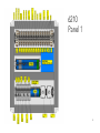
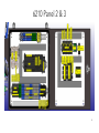
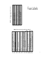
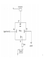
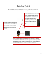
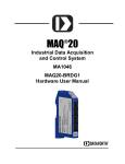
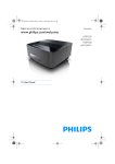
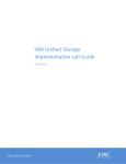
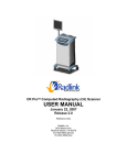
Service Manual Revised October 26, 2016 1 15 PSI Pressure Relief Valve Low Water Cut Off Water Level Sensor Steam Valves Steam Pressure Sensor 1 Operating Pressure Limit Switch Steam Pressure Gauge High Pressure Limit Switch Steam Pressure Sensor 2 Steam Purge Valve Boiler Water Temp. Sensor Water Purge Valve Flue Temp. Sensor Boiler Door Temp. Sensor Furnace Sight Glass Circulation Water Pump Boiler Water Sight Glass Feed Water Pump Feed Water Temp. Sensor Feed Water Valve Boiler Drain Valve 2 Air Flow Switch Gun Assembly Burner Cone Fuel Nozzles Fuel Pump Fuel Pressure Gauge Louver Actuator Fuel Pressure Sensor 3 IR Flame Sensor Ignition Transformer Control Switch Fan Motor Ignition Electrode Propane Regulator Fuel Valves Propane Valve Propane Pressure Sensor 4 6210 Panel 1 5 6210 Panel 2 & 3 6 24 VDC to C-more Touch 24 VDC to Discrete Outputs, all Analog Sensors, Safety Relays 24 VDC to all PLC Input and Output Cards 24 VDC to Ethernet Switch 24 VDC Power to PLC 12 VDC to 24 VDC Power Converter 24 VDC to fuse 6 (1.5) C-More Touch Screen 12 VDC to ON/OFF Switch on (0.5) Position Switches 24 VDC to Louver Actuator (1.5) Screen (2) (2) (2) (1.5) (5) (15) (2) Work Lights 12 VDC to 12 VDC Power (15) Converter 12 VDC Generator Start/Stop (15) 12 VDC to all Valves and (5) Louver Actuator (5) Feed Water Valve (5) Blow Down Valve (5) Steam Purge/Manifold Drain (5) Steam Valve 4 (5) Steam Valve 3 (5) Steam Valve 1 (5) Steam Valve 2 Note: All fuses are Buss Type AGC-5-R Fuse Labels F1 F2 F3 F4 F5 F6 F7 F8 Note: All fuses are Buss Type AGC-(Amp Rating)-R F1 F2 F3 F4 F5 F6 F7 F8 F9 F10 F11 F12 7 8 C-More Touch Screen Power Diagram 9 Safety Circuit Diagram 1 This 24 VDC provides the safety relays with the 24 VDC power for the signal to the PLC. It is jumpered from Air Flow Switch through Control Power. 2 9 A1 A2 9 A1 A2 9 24 VDC Signal to PLC X6 A1 A2 9 A1 A2 9 A1 A2 9 24 VDC Signal to PLC X7 24 VDC Signal to PLC X5 5 Burner Relay 5 A1 A2 9 Air Flow Switch 5 Fan VFD 24 VDC Signal to PLC X3 24Signal VDC Signal to PLC to PLC X0X4 24 VDC Signal to PLC X2 A1 A2 5 OPLS 24 VDC Signal to PLC X1 5 HPLS 5 Control Power 5 Low Water 2 120 VAC to Safety Relays Low Water 1 Burner Control Switch 24 VDC Signal to PLC X0 24 VDC to Safety Relays 1 The safety relays are used to tell the PLC the state of each safety device. Each device recieves its power at (A1) on the relay before it. When the switch inside a safety device closes it provides 120 VAC to the safety relay which closes the relay sending a 24 VDC to the PLC to indicate the safety switch is closed. It also provides the Power supply to the next safety device. 3 When the "Burner On/Off" switch on the control panel door (Above) is turned on, it introduces 120 VAC power into the safety circuit. 5 OPLS and HPLS are normall closed. they open when steam pressure reaches their set point. OPLS=14 PSI, HPLS=15 PSI. Power cascades down the chain through each safety device through the Black, Grey, Blue, and Orange circuits to the right. LWCO 1 LWCO 2 4 LWCO 1 and LWCO 2 are normally open. They close when probes contact water in the boiler. (See "Low Water Cut Off" diagram for more detail.) 12 VDC Power 24 VDC to all 24 VDC Components +12 VDC power from Battery -12 VDC from Battery 24 VDC Power 12 VDC to 24VDC Power Converter _ + Ground +12 VDC from Relay +12 VDC Supply to Relay When 12 VDC power is applied to (86) The contacts close between (30) and (87) to provide 12 VDC power to the system +12 VDC from Battery -12 VDC from Battery 24 VDC to Safety Relays <1 1< <2 2< <3 3< <4 4< 10 Safety Circuit Diagram 2 This 24 VDC provides the safety relays with the 24 VDC power for the signal to the PLC. It is jumpered from Air Flow Switch Relay through the Control Power Relay. 2 24 VDC to Safety Relays 13 9 24 VDC Signal to PLC X5 24 VDC Signal to PLC X6 5 5 5 5 24 VDC Signal to PLC X7 24 VDC Signal to PLC X3 24 VDC Signal to PLC X2 5 24Signal VDC Signal to PLC to PLC X0X4 24 VDC Signal to PLC X1 5 A1 A2 9 A1 A2 9 A1 A2 9 A1 A2 9 A1 A2 9 A1 A2 9 9 A1 A2 9 Air Flow Switch Burner Relay A1 A2 Fan VFD OPLS HPLS Low Water 2 Control Power CR 1 14 CR 2 5 12 5 5 Low Water 1 8 24 VDC Signal to PLC X0 120 VAC from Burner Relay to Safety Relay Chain 120 VAC from OPLS to Burner Relay When CR 1 receives a 120 VAC signal from the Honeywell Burner Controller on (14), Contacts close between (12)-(8) and (9)-(5) on CR1. (12)-(8) sends a 12 VDC signal to (2) on the VFD to start the fan. (9)-(5) sends 120 VAC to the Air Flow Switch and to the VFD relay in the safety chain to tell the PLC that the VFD has been started. 1 The safety relays are used to tell the PLC the state of each safety device. Each device recieves its power at (A1) on the relay before it. When the switch inside a safety device closes it provides 120 VAC to the safety relay which closes the relay sending a 24 VDC to the PLC to indicate the safety switch is closed. It also provides the Power supply to the next safety device. Honeywell Burner Control Air Flow Switch 3 Once power has progressed to the OPLS, the PLC turns on the burner relay which sends a 120 VAC signal to (6) on the Honeywell that it is safe to start the burner. The Honeywell sends a 120 VAC signal out to the CR1 to start the fan on (5). 1 1 1 1 2 2 2 2 2 2 3 5 5 6 6 7 7 8 9 10 11 12 13 14 14 14 15 16 17 18 19 20 21 22 23 24 Once the fan starts and the Air Flow Switch closes the Honeywell receives a 120 VAC signal on (7) that it is safe to procede. 6 120 VAC from Air Flow Switch 120 VAC to Air Flow Switch 12 VDC Common Ground 12 VDC to CR1 12 VDC From CR1 120 VAC from OPLS (See Safety Ciruit Dagram 1) VFD 1 2 5 6 11 12 2 14 13A 13B 13C 15 25 2 30 31 TXA TXB LWCO 1 LWCO 2 12 VDC Power 24 VDC to all 24 VDC Components +12 VDC power from Battery 24 VDC Power 12 VDC to 24VDC Power Converter _ + -12 VDC from Battery Burner Control Switch 5 Whenever the VFD is supplied with 240 VAC current, which is any time the generator is running, the Blu/Blk wire from (14) on the VFD should be supplied with 12 VDC power. this closes the contacts between (9) and (5) on CR 2 wich provides 120 VAC, through the Blue wire, to (9) on CR 1 Ground +12 VDC from Relay +12 VDC Supply to Relay When 12 VDC power is applied to (86) The contacts close between (30) and (87) to provide 12 VDC power to the system +12 VDC from Battery -12 VDC from Battery 24 VDC to Safety Relays <1 1< <2 2< <3 3< <4 4< 4 11 LWCO Diagram 2 The red wire below provides the safety relays with the 24 VDC power for the signal to the PLC.It is jumpered from Air Flow Switch through Control Power. The yellow wires below are the 24 VDC signal from the PLC to the Low Water 1 Test and Low Water 1 Reset 7 24 VDC to Low Water 2 Reset 24 VDC to Low Water 1 Test Ground 24 VDC to Safety Relays 11 5 5 5 5 5 5 A1 A2 9 A1 A2 9 9 A1 A2 9 A1 A2 9 9 A1 A2 Low Water 2 Reset Air Flow Switch Fan VFD A1 A2 Low Water 1 Test HPLS A1 A2 OPLS 1 Burner Relay 3 5 Low Water 2 Control Power 120 VAC to Safety Relays When the "Burner On/Off" switch on the control panel door is turned on, it introduces 120 VAC power into the safety circuit. 5 Low Water 1 The safety relays are used to tell the PLC the state of each safety 5 device. Each device recieves its power at (A1) on the relay before it. When the switch inside a safety device closes it provides 120 VAC to the safety relay which closes the relay sending a 24 VDC A1 A2 to the PLC to indicate the safety switch is closed. It also provides the 9 Power supply to the next safety device. Burner Control Switch A1 A2 9 A1 A2 9 9 6 Low Water 1 Test is normally open. when it receives 24 VDC from the PLC on (A1), contacts close between (9) and (5) to simulate a Low Water 1 fault. Low Water 2 Reset is normally closed. When it receives 24 VDC from the PLC on (A1), contacts open between (9) and (1) to reset LWCO 2. Power cascades down the chain through each safety device beginning with Low Water 1 and Low Water 2 4 Black and Grey wires carry 120 VAC to and from LWCO relays 3 4 5 _ + The LWCO sensor relays detect water in the boiler by sensing resistance between the probe which is connected to (6) and ground which is connected at (5). When resistance is detected, contacts close between (1) and (10). This closes the circuit for this link in the safety chain and sends 120 VAC power to the safety relay in the safety chain. (See #1 above) (See "Safety Circuit Diagram 1" & "Safety Circuit Diagram 2") 2 1 11 10 LWCO 1 5 6 7 9 3 8 4 2 1 11 10 LWCO 2 5 6 7 9 8 8 (7) and (8) on LWCO 1 are connected to Low Water 1 Test relay which is a normally open relay. Since this is a normally open circuit LWCO 1 will automatically reset once water is detected after a Low Water 1 fault If the relay is closed it will cause the contacts between (1) and (10) to open simulating a Low Water 1 fault. 12 VDC Power e -12 VDC from Battery +12 VDC power from Battery 24 VDC Power 24 VDC to all 24 VDC Components (See relays above for more details.) 12 VDC to 24VDC Power Converter (7) and (8) on LWCO 2 are connected to Low Water 2 Reset relay which is a normally closed relay. If there is a Low Water 2 fault, the circuit between (7) and (8) must be broken to reset the relay. Water must be detected when the relay is reset, otherwise the Low Water 2 fault will return immediately Ground +12 VDC from Relay +12 VDC Supply to Relay When 12 VDC power is applied to (86) The contacts close between (30) and (87) to provide 12 VDC power to the system +12 VDC from Battery -12 VDC from Battery 24 VDC to Safety Relays <1 <2 <3 <4 1< 2< 3< 4< 12 Louver Actuator Diagram Mod-Bus Connection from Honeywell to PLC 120 VAC power supply to high fire and low fire switch relays Normal Opera�on 120 VAC from low fire switch relay 120 VAC from high fire switch relay The “Louver Actuator”controls how far the air louver will open which controls the amount of air flow through the burner. The Louver Actuator works in connec�on with two separate control systems in the burner,the “PLC”and the “Honyewell Burner Controller”. The PLC controls the ac�on of the Louver Actuator. The Honeywell Burner Controller is a safety device which confirms that all func�ons are being carried out safely and correctly. There are two separate systems inside the Louver Actuator which interact with these two control systems. The 4-20 mA signal and the 12 VDC power work together with the PLC to open and close the louver to the correct posi�on. The 24 VDC power runs through posi�on switches which communicate with the Honeywell Burner Controller to verify that the purge cycle was completed correctly. During normal opera�on, when the burner state is “Run,”the PLC controls the opening and closing of the actuator for low and high fire. This is determined by the steam pressure in the boiler which is sensed by the two pressure transducers on the top front of the boiler. The 4-20 mA signal from the PLC tells the Louver Actuator how far it should be open. The 12 VDC motor inside the Louver Actuator drives the Louver open to the posi�on called for by the 4-20 mA signal. The Honeywell Burner Controller does not care what the Louver Actuator is doing when the burner state is “Run.” 120 VAC Power from control relay see 120 VAC control power For the burner to ignite safely,an effec�ve purge cycle must be completed. For an effec�ve purge cycle to take place the air louver must open completely and the fan must move air through the completely open louver for 30 seconds. The Honeywell Burner controller uses the 24 VDC posi�on switches in the “Louver Actuator” to confirm that an effec�ve purge has taken place. When the burner ini�ates the Honeywell Burner Controller will call for a purge cycle, it will start the fan, it will send a signal to the PLC through the Mod-Bus connec�on that it wants to purge,it will go into a “Purge Hold”state and wait un�l it receives a signal that the louver is open. The PLC will tell the Louver Actuator to open completely. Once the actuator has opened beyond the “High Fire Switch,”the “High Fire Switch”will close, sending 24 VDC power to the “High Fire Switch Relay”which will close the relay sending a 120 VAC signal to the Honeywell Burner Controller, telling it that the louver has opened. The Honeywell Burner Controller will then go to the “purge”state. The burner will purge for 30 seconds. A�er the purge is complete, the Honeywell Burner Controller will tell the PLC, through the Mod-Bus connec�on, that the purge is complete it will go into a “Purge Hold”state again and wait un�l it receives a signal that the louver is closed. The PLC will tell the Louver Actuator to close. Once the actuator has closed beyond the “Low Fire Switch,”the “Low Fire Switch”will close sending 24 VDC power to the “LowFire Switch Relay”which will close the relay sending a 120 VAC signal to the Honeywell Burner Controller, telling it that the louver has closed.The Honeywell Burner Controller will then progress to “Pilot Igni�on.” _ + +12 VDC Power +24 VDC to Position Switches +24 VDC From High Fire Switch (when louver is open) +24 VDC From Low Fire Switch (when louver is closed) 24 VDC to Analog Output Card 12 VDC Power When 12 VDC power is applied to (86) The contacts close between (30) and (87) to provide 12 VDC power to the system <1 <2 <3 <4 <5 <6 <7 <8 1< 2< 3< 4< 5< 6< 7< 8< 24 VDC Power Converter +12 VDC to Louver Actuator <3 3< <4 4< -12 VDC (Ground) 24 VDC to Louver Position Switches Ground +12 VDC from Relay +12 VDC Supply to Relay <1 1< <2 2< 4-20 mA common Ground CH8> COM> COM> +24V> 0V> +12 VDC from Battery -12 VDC from Battery 4-20 mA signal from PLC 24 VDC to all 24 VDC Components 9 12 VDC power to Actuator A1 A2 9 12 VDC to 24VDC Power Converter A1 A2 When position switches in actuator close, 24 VDC is applied to (A2), contacts close between (9) and (5) sending 120 VAC to the Honeywell Burner Controller which confirms that the louver is in the correct position 120 VAC to Relays 5 12 VDC Power -12 VDC from Battery +12 VDC power from Battery 120 VAC from Relay 120 VAC from Relay 5 13 Pump Wiring Pump Wiring Yellow/Black Black Brown Cap Orange White Yellow White Ground Green 14 Safety Circuit The safety circuit is a chain of switches that determine whether the burner may be operated safely. The circuit is designed so that each switch, when closed, provides the power for the next switch in the chain. In order for the fire to run, power must reach the end of the chain. 120 VAC power is introduced into the chain when the “Burner On/Off” switch, on the control panel door, is turned on. Power flows down the chain as each switch closes. Each component in the system will be discussed in more detail later. 15 Safety Relays In order for the PLC to know the state of the safety circuit, a 24 VDC signal must be sent from each component in the circuit to the PLC. To accomplish this we use a series of relays that is supplied with 24 VDC power and is switched by the 120 VAC as it flows through the safety device circuit. The safety relays are normally open. (A2) is a common neutral 120 VAC for all relays, (9) is always supplied with 24 VDC power, When a safety switch in the system closes it allows 120 VAC power to flow to (A1). When (A1) receives 120 VAC from the switch, contacts close between (9) and (5) sending the 24 VDC signal to the PLC that the safety switch is closed. The 120 VAC supply for the next safety switch in the chain is also connected to (A1). Therefore, when (A1) receives power it tells the PLC that the switch is closed and it provides power to the next switch in the chain. In this way the power cascades down the safety circuit sending information to the PLC along the way. (See “Safety Circuit Diagram 1” & “Safety Circuit Diagram 2” for details.) 16 Sequence 17 Sequence As each safety device engages and the signal is sent to the PLC, indicators on the “Systems Start” screen will turn green to indicate that the device is engaged. Remember: The Safety Relays send this signal to the PLC. If the device is engaged but the PLC is not receiving the signal that it is engaged, check the relay. 18 Burner Relay The Burner Relay is the switch the PLC uses to turn the burner on and off. It is located in the safety chain after the safeties for water level and pressure. Therefore if for any reason a safety trips for water level or pressure it will cut off the power to the relay and shut off the burner regardless of what the PLC is telling it to do. The Burner Relay is located in the bottom right corner of panel 2. It receives a 24 VDC signal to the coil from the PLC which switches the 120 VAC power in the safety circuit. (See “Safety Circuit Diagram 2.”) 19 Burner Relay Certain conditions must be met before the PLC will turn on the Burner Relay: 1. 2. 3. 4. 5. Low Water Cut Off 1 and Low Water Cut Off 2 must be engaged. (See “Low Water Cut Off.”) High Pressure Limit Switch must be engaged (See “High Pressure Limit Switch (HPLS).”) Operating Pressure Limit Switch must be engaged (See “Operating Pressure Limit Switch (OPLS).”) Water level in the boiler must reach the “Boiler Water Level Target”(See “Water Level Control.”) Steam pressure must be below operating set point (See “Steam Pressure Control.”) 20 Burner Relay Once all the conditions for start-up are met, the PLC sends a 24 VDC signal here to close the relay When the coil receives 24 VDC from the PLC, Contacts close supplying this wire with 120 VAC (See “Safety Circuit Diagram 1”) If water level and steam pressure are within normal limits for operation, this terminal will be supplied with 120 VAC (See “Safety Circuit Diagram 1”) 21 High Pressure Limit Switch (HPLS) The HPLS is a safety device which shuts off the fire if the steam pressure in the boiler gets too high. The HPLS is normally closed as long as the steam pressure is below the set point. If the steam pressure exceeds the set point, the switch trips and breaks the safety circuit which shuts down the fire. The HPLS should only trip if the OPLS fails to shut off the flame (See Operating Pressure Limit Switch). When steam pressure drop back below the set point, The HPLS requires a manual reset to let the burner restart. (see Safety “Circuit Diagram 1” and “Safety Circuit Daigram 2”) To reset the HPLS pressure in the boiler must drop below the set point and the switch must be reset manually by pressing firmly on reset button on top of the sensor. 22 High Pressure Limit Switch (HPLS) The HPLS set point may be adjusted by turning this nut. Since the HPLS is a backup to the OPLS it is normally set 1 PSI higher than the OPLS • Clockwise increases set point. • Counter clockwise decreases set point Operating Range Recommended Set Point 0-15 PSI 15 PSI 23 Low Water Cut Off (LWCO) The Low Water Cut Off (LWCO) is a safety device designed to ensure that the water level in the boiler never drops below a safe level during operation. The LWCO consists of two probes. One is slightly longer than the other. Each probe is a totally separate sensor from the other. The tip of the probes sit at the lowest safe level in the boiler. When the water level in the boiler rises enough that it touches the tip of the probe, the LWCO knows that the water is high enough to safely operate. If the water level in the boiler drops so that the water is no longer touching the probe, the LWCO knows that the water is below the safe operating level and shuts off the burner. The Low Water Cut Off has only two Functions: 1. Shut off the burner if water level drops below safe level 2. Tells the PLC to start the Circulation Pump when the LWCO is engaged. See “LWCO Diagram” for more detail on the Low Water Cut Off. 24 Operating Pressure Limit Switch (OPLS) The OPLS is a safety device uses to shut off the fire if the steam pressure in the boiler gets too high. The OPLS is normally closed as long as the steam pressure is below the set point. If the steam pressure exceeds the set point, the switch trips and breaks the safety circuit which shuts down the fire. When steam pressure drop back below the set point, The OPLS will automatically reset. (see Safety “Circuit Diagram 1” and “Safety Circuit Daigram 2”) 25 Operating Pressure Limit Switch (OPLS) The OPLS set point may be adjusted by turning this nut. • Clockwise increases set point. • Counter clockwise decreases set point Operating Range Recommended Set Point 0-15 psi 14 psi 26 Water System The purpose of the water system is to provide the boiler with water and maintain the proper water level during operation. It is essential for both function and safety that the water inside the boiler is maintained at an appropriate level. Outlet The Water System can be broken down into 4 main parts: 1. 2. 3. 4. Controls and Safeties Supply Water (Blue) Feed Water (Purple) Circulation (Red) Inlet 27 Water System Boiler Water Temp. Sensor Y-Strainer Feed Water Temp. Sensor Outlet Circulation Pump Feed Water Valve Feed Water Pump T-Strainer Supply Water Shut-Off Valve Inlet 28 Water System Circulation Hot water is pulled out of the boiler. It passes through the Y-strainer to the circulation pump. It is then pumped to the feed water pipe where it mixes with the cold supply water as it enters the boiler. Outlet Feed Water The warm mixed water from the supply water and circulation water enters the boiler. Supply Water Cold water is pulled in through the bulk head fittings in the water tanks. It passes through the supply water shut off valve and T-strainer to the feed water pump. It is then pumped through the feed water valve and mixed with the hot circulation water as it Inlet enters the boiler 29 Water Level Control There are 2 main factors that will affect the water level in the boiler, the supply water system and the feed water control system. In order for the water level in the boiler to be controlled properly both of these systems must be functioning correctly. Feed Water Control System Supply Water System 30 Supply Water System The supply water system contains the water tanks, the supply water shut off valve, the T-strainer and the feed water pump. Water tanks are the source of water to fill the boiler. They must have water in them The feed water pump pumps the water into the boiler. It should be running any time the water system is active. The supply water shut off valve stops the flow of water to the Tstrainer so that is can be cleaned without spilling water all over the ground. It must be open to allow water supply to the feed water pump The T-strainer stops particles in the supply water from being pumped into the boiler. It should be cleaned every time the water tanks are filled. If it is not cleaned frequently it will plug and stop the water flow into the boiler. 31 Water Level Control This consists of three components, the boiler water level sensor, the PLC, and the feed water valve. The feed water valve opens to allow water to flow into the boiler to raise the water level. When the water has reached the correct level inside the boiler the valve closes to stop the flow of water into the boiler. The boiler water level sensor measures the level of the water in the boiler and sends a signal to the PLC to indicate what the water level is. The water level in the boiler is measured in inches and should correspond to the level in the sight glass on the upper right side of the boiler. The PLC is programmed to maintain the boiler water level at a set point (Default 5 in.). When the boiler water level sensor indicates that the water level has dropped below the set point, the PLC tells the feed water valve to open to allow water to flow into the boiler. When the water level reaches the set point the PLC tells the valve to close which stops the flow of water into the boiler. 32 Water System Safeties (Low Water Cut Off) The Low Water Cut Off (LWCO) is a safety device designed to ensure that the water level in the boiler never drops below a safe level during operation. The LWCO consists of two probes. One is slightly longer than the other. Each probe is a totally separate sensor from the other. The tip of the probes sit at the lowest safe level in the boiler. When the water level in the boiler rises enough that it touches the tip of the probe, the LWCO knows that the water is high enough to safely operate. If the water level in the boiler drops so that the water is no longer touching the probe, the LWCO knows that the water is below the safe operating level. The only function of the LWCO is to shut off the flame if the boiler water level drops below the safe operating level. It does not have any effect on water level control. See “Safety Circuit” for more detail on the Low Water Cut Off. 33 Feed Water Pump The Feed Water Pump is used to pump the supply water from the water tanks to the boiler. The Feed Water Pump runs anytime the water system is active. The flow of water from the Feed Water Pump to the boiler is controlled by the Feed Water Valve (See “Feed Water Valve”). 34 Circulation Pump The Circulation Pump is used to pull hot water out of the boiler and circulate it back through the feed water pipe. The circulation pump will not run until the water system is active and Low Water 1 is closed (water is above Low Water 1). 35 Feed Water Valve The Feed Water Valve controls the flow of supply water into the boiler to maintain the proper water level. 36 Boiler Water Temp. and Feed Water Temp. Sensors Circulation Water Temp. Boiler Water Temp. The Boiler Water and Circulation Water Temp. sensors are both critical for boiler operation. When the boiler is heating up the burner will not go to high fire until the Outlet boiler water temp. reaches 180 degrees F. During operation the PLC is always comparing the readings from both sensors. Both sensors are exactly the same and can be interchangeable if needed. Inlet 37 Boiler Water Temp. and Feed Water Temp. Sensors Field Work The readings from the Boiler Water Temp. and Feed Water Temp. sensors can be seen on the touch screen controller on the two screens to the right. The feed water will normally be cooler than the boiler water when the Feed Water Valve is open. When the Feed Water Valve is closed the two sensors will normally read very close to the same. Outlet (Menu)(Diagnostics)(Inputs/Outputs) (Analog Inputs) Sensor Normal Operating Range Boiler Water 220-250 deg. F Feed Water 120-250 deg. F Default temp differential set point = 150 deg. F Inl et 38 Boiler Water Temp. and Feed Water Temp. Alarm Settings Outlet If the feed water is too much cooler than the boiler water, (150 deg. F) it indicates a failure in the circulation system and gives an alarm to the operator. The temperature differential set point can be adjusted by going to (Menu)(Settings)(Alarm Settings) on the touch screen controller and adjusting the set point here. The temperature differential alarm can be disabled by going to (Menu)(Settings)(Alarm Status) on the touch screen controller and disable alarm here. Make sure to read warningInlet to the right when disabling alarm. 39 Electrical path of the Boiler Water Level Sensor: Troubleshooting Guide Boiler Water Level Sensor DewPoint 6210 40 Staheli West Inc. • 600 N. Airport Road • Cedar City, Utah • 435.586.8002 • [email protected] Staheli West Inc. • 600 N. Airport Road • Cedar City, Utah • 435.586.8002 • [email protected] 41 Staheli West Inc. • 600 N. Airport Road • Cedar City, Utah • 435.586.8002 • [email protected] Staheli West Inc. • 600 N. Airport Road • Cedar City, Utah • 435.586.8002 • [email protected] 4-20 mA VRO Trouble Shooting Test individual components of system to isolate problem. 1. Test Sensor Output a. Turn off power b. Disconnect sensor wires from signal conditioner. c. Sensor is now a potentiometer with the i. Black wire being the wiper and ii. Red & Yellow wires the ends of the potentiometer. d. With an ohmmeter connect between Red & Black wires. The closer the float is to full the higher the resistance typically 500 to 750 ohms. Move the float toward the empty end of the sensor and the resistance will decrease. e. With an ohmmeter connect between Black & Yellow wires. The closer the float is to full the lower the resistance typically will be less than 100 ohms. Move the float toward the empty end of the sensor and the resistance will increase. f. With an ohmmeter connect between Red & Yellow wires the resistance will not change with float movement. The resistance will be 600-750 ohms. g. The resistance tests above must never be above 900 ohms. h. If the sensor output changes as described above the sensor is good. i. Reconnect sensor wires to signal conditioner. 2. Test Signal Conditioner a. Turn off power. b. Disconnect any wires from the two position terminal block. c. Measure the incoming power voltage this must be 10-28 VDC. d. With an amp meter set to measure milliamps DC. i. Connect a 250 ohm resistor to the signal terminal on the signal conditioner. ii. Connect meter positive lead to loose end of 250 ohm resistor. iii. Connect meter negative lead to power supply GROUND. iv. Connect power to plus terminal on the signal conditioner terminal block. e. If the float on the sensor cannot be moved (i.e. remote location or installed in tank), verify signal conditioner output is between 4-20 mA. f. If the float on the sensor can be moved, slide the float to the empty position and verify 4 mA output. g. Adjust zero pot. on signal conditioner if required to get 4 mA when float is at empty position. h. Next slide the float to the full position and verify 20 mA output. i. Adjust gain pot. on signal conditioner if required to get 20 mA when float is at the full point. j. Finally slowly move the float up and down the full length of the stem, watching the meter for abnormal output readings. k. Now the sensor and signal conditioner test good. Any errors in readings when connected in your application may be the result of: i. How the signal conditioner wires are routed ii. Grounding of sensor and tank iii. Or other application & installation issues. Staheli West Inc. • 600 N. Airport Road • Cedar City, Utah • 435.586.8002 • [email protected] Signal Conditioners Continuous Output Sensor to 4-20 mA 4-20 mA Output Loop Powered: • 24 Vdc powered from loop • Adjustable Zero, 4 ma output by 25 turn sealed pot. • Adjustable Gain, 20 ma output by 25 turn sealed pot. • Two piece terminal blocks, plug-in for easy wiring • Load resistor typically 250 ohms • Epoxy sealed electronics for industrial applications • Reverse polarity protected • Voltage spike and surge protected Ordering Information: Part number: SCL-BM0BB Staheli West Inc. • 600 N. Airport Road • Cedar City, Utah • 435.586.8002 • [email protected] 42 Feed Water Valve The Feed Water Valve controls the flow of supply water into the boiler to maintain the proper water level (See “Water Level Control” for more detail). The valve is a 1 in. STD port brass ball valve. It is driven by an EH2 4-20 mA actuator. The Feed Water Valve is located inside the back door here. 43 Feed Water Pump The Feed Water Pump is used to pump the supply water from the water tanks to the boiler. The Feed Water Pump runs anytime the water system is active. The flow of water from the Feed Water Pump to the boiler is controlled by the Feed Water Valve (See “Feed Water Valve”). This pump requires little or no service other than reasonable care and periodic cleaning. Occasionally, however, a shaft seal may become damaged and must be replaced. The procedure as outlined on the next page will enable you to replace the seal. 44 Circulation Pump The Circulation Pump is used to pull hot water out of the boiler and circulate it back through the feed water pipe. The circulation pump runs any time the water system is active and Low Water 1 is closed (water is above Low Water 1). This pump requires little or no service other than reasonable care and periodic cleaning. Occasionally, however, a shaft seal may become damaged and must be replaced. The procedure as outlined on the next page will enable you to replace the seal. 45 Pump Service NOTICE: The highly polished and lapped faces of this seal are easily damaged. Read instructions and handle the seal with care. Some models are equipped with an impeller screw, which has a left hand thread. Before unscrewing the impeller, remove the impeller screw. REMOVAL OF OLD SEAL 1. After unscrewing impeller, carefully remove rotating part of seal by prying up on sealing washer, using two screw drivers (see Figure 5A). Use care not to scratch motor shaft. 2. Remove seal plate from motor and place on flat surface, face down. Use a screwdriver to push ceramic seat out from seal cavity (see Figure 5B). INSTALLATION OF FLOATING SEAT (Figure 5C) 1. Clean polished surface of floating seat with clean cloth. 2. Turn seal plate over so seal cavity is up, clean cavity thoroughly. 3. Lubricate outside rubber surface of ceramic seat with soapy water and press firmly into seal cavity with finger pressure. If seat will not locate properly in this manner, place cardboard washer over polished face of seat and press into seal cavity using a 3/4" socket or 3/4" piece of standard pipe. 4. DISPOSE OF CARDBOARD WASHER. Be sure polished surface of seat is free of dirt and has not been damaged by insertion. Remove excess soapy water. INSTALLATION OF ROTATING PART OF SEAL UNIT (Figure 5D) 1. Reinstall seal plate using extreme caution not to hit ceramic portion of seal on motor shaft. 2. Inspect shaft to make sure that it is clean. 3. Clean face of sealing washer with clean cloth. 4. Lubricate inside diameter and outer face of rubber drive ring with soapy water and slide assembly on motor shaft (sealing face first) until rubber drive ring hits shaft shoulder. 5. Screw impeller on shaft until impeller hub hits shaft shoulder. This will automatically locate seal in place and move the sealing washer face up against seat facing. Reinstall impeller screw (if used). 46 Pump Service 47 Y-Strainer The Y-strainer will catch any large particles as the boiler water is pulled out and recirculated. The Y-strainer should be flushed at the end of each day by opening the hand valve on the front for several seconds. If the Y-strainer is not flushed often it will cause malfunction of the circulation system. If the screen inside the Y-strainer becomes damaged or permanently plugged, the screen can be easily replaced. Y-Strainer Flush 48 Steam Pressure Control This system consists of three components, the Steam Pressure Transducers, the PLC and the Burner. The Burner provides the fire which increases the pressure inside the boiler. The burner alternates between Low Fire, High Fire and Off depending on the steam pressure demand. The two pressure transducers sense the pressure inside the boiler and send that information to the PLC. The PLC receives the signal from the Steam Pressure Transducers and switches the burner between Low Fire, High Fire and Off to maintain the correct steam pressure. 49 Steam Pressure Control Logic Because steam pressure is such a critical measurement, the two Steam Pressure Transducers both measure the steam pressure inside the boiler. The PLC compares the readings from each sensor and calculates the average for the actual steam pressure reading. The steam pressure reading from the pressure transducers is displayed here on the field work screen. 50 Steam Pressure Control Logic If the readings from the two pressure transducers are ever more than 2 psi different from each other, an error message will appear that will require the operator to select which transducer matches the reading on the mechanical gauge. The selection can be made by selecting the sensor that matches, directly from the error message… or by going to MenuàSettingsàBoiler PressureàPressure Sensor Selectionà and select the matching sensor. The DewPoint may be operated on one sensor for a short period of time until the bad sensor can be replaced. All pressure safety devices will still function normally. However, to ensure accurate steam pressure control the DewPoint should never be operated for an extended time with one Steam Pressure Transducer. 51 Steam Pressure Control Logic The PLC automatically adjusts the flame between Low Fire, High Fire and Off to keep the steam pressure within 1 psi of the “Boiler Steam Pressure Operating Target.” The logic for this is: • High Fire: When steam pressure is more than 1 psi below the Operating Target and the boiler water is more than 180 deg., the Burner goes to “High Fire” • Low Fire: When steam pressure is within 1 psi (+ or -‐) and/or the boiler water is below 180 degrees of the Operating Target, the Burner goes to “Low Fire” • Off: When the steam pressure is more than 1 psi greater than the Operating Target, the burner goes to off. The “Boiler Steam Pressure Operating Target” can be found by going to MenuàSettingsàBoiler Pressure. 52 Actuators The EH2 4-20 mA actuator is used in several locations on the machine. It receives an analog signal from the PLC which can range from Closed to 100% open and anywhere in between. It has a four pin plug and a red position indicator. It can be interchanged with any actuator that has the same plug EH2 4-20 mA The EH2 On/Off actuator is used on the steam purge valve. It receives a discrete signal from the PLC which tells the actuator to open or close completely. It has a three pin plug and a yellow position indicator. It can be interchanged with any actuator that has the same plug. EH2 On/Off The EH3 4-20 mA actuator with position switches is a very specialized actuator that is used to control the airflow to the burner. It receives an analog signal from the PLC which can range from Closed to 100% open and anywhere in between. It has an eight pin plug and a red position indicator. (For more detail see “Louver Actuator”) EH3 4-20 mA with Position Switches The EH3 On/Off actuator is used on the manifold drain valve. It receives a discrete signal from the PLC which tells the actuator to open or close completely. It has a three pin plug and a yellow position indicator. It can be interchanged with any actuator that has the same plug. EH3 On/Off 53 Blow Down Valve The Blow Down Valve opens to let concentrated water out of the boiler to maintain good water quality inside the boiler (See “Automatic Blow Down System” for more detail). The valve is a 1 in. STD port brass ball valve. It is driven by an EH2 4-20 mA actuator. The Blow Down Valve is located inside the back door here. 54 Manifold Drain Valve The Manifold Drain Valve opens to drain any water that has accumulated in the bottom of the steam manifold. It normally opens for 30 seconds and closes for 30 seconds. The open time can be changed in settings. The valve is a 0.5 in. standard port brass ball valve. It is driven by an EH3 On/Off actuator. The Manifold Drain Valve is located on the bottom of the steam manifold here. 55 Steam Purge Valve The Purpose of the steam purge valve is to keep the steam pressure low enough that the burner will not shut off when turning around or using low steam rates. This prevents big drops in steam pressure because of the burner shutting off during operation. The steam purge valve uses a 1 in. full port valve with an EH2 On/Off actuator. The steam purge valve is located in the middle of the steam manifold. 56 Steam Valve The steam valves control the steam rate to the corresponding steam manifold in the baler. They are a 1.5 in. standard port brass ball valve with an EH2 4-20 mA actuator. The steam purge valve is located in the middle of the steam manifold. 57 Valve Repair Before you begin turn the valve to the fully closed position Be careful not to damage the surfaces on the valve where the seats will need to seal. 1. Remove the retainer nut from the end of the valve and remove the outer seat and the ball. (the ball must be in the closed position before it can be removed) 2. Remove the retainer nut on the stud at the top of the valve. 3. Remove the stud and the inner seal by pressing the stud down into the valve and out the end. 4. Remove the outer seal 5. Remove the inner seat To re-assemble do these steps in reverse with the new parts. 58 DewPoint 6210 Startup Timeline DewPoint 6210 Start-Up Timeline 1 Generator Starts and Runs 2 Feed Water Pump Turns On and Runs 3 Feed Water Actuator Opens and lets water into the Boiler until Boiler reaches operating level 4 Burner Control Power comes on automatically (unless manually shut off) 5 Low Water Cut Off Probe #2 makes contact with Boiler Water 6 Low Water Cut Off Probe #1 makes contact with Boiler Water and satisfies Both LWCO safeties at this time 7 Circulation Pump Turns On 8 Burner Controller checks for overpressure (over 15 existing Boiler PSI) in the boiler by Checking the "High Pressure Limit" sensor 9 Burner Controller checks for overpressure (over 14.5 existing Boiler PSI) in the boiler by Checking the "Operating Pressure Control" sensor 10 System Waits for the "Burner Relay" to be initiated (done automatically during a "Start All" or done manually if system was started using "Start Fill") 11 Burner Relay is active (After the Target Boiler Water level is satisfied the program sequence to the next step) 12 Burner Initiate (Checks that Voltage and Frequency tolerances are met) 13 Burner Standby (Checks that all safeties are in their correct state) 14 Fan VFD turns On and begins to spin the Fan 15 Pre-purge (Power is sent to the Fan Motor and the Air Louver opens to 100%) 16 Air Flow Switch must confirm the Fan started and air is moving through the Burner 17 Purge goes for 30 seconds 18 Burner Louver goes completely closed at the end of the 30 second Purge cycle 19 Propane solenoid opens and the Ignition Transformer sparks for 10 seconds 20 Pilot Flame is sensed with the IR Flame Detector 21 Main Fuel Valve #1 and the Safety fuel valve (Main Valve #2) open to start Main Oil Ignition 22 Main flame is verified using the IR flame sensor 23 Burner advances to Low Fire 24 Burner heats the Boiler Water on Low Fire until the Boiler Water reaches 180 degrees F 25 Burner goes to High Fire after the Boiler Water Temp gets above 180 degrees F 26 Burner stays on High Fire until the target pressure is reached (Default 12 PSI) 27 Steam Purge Valve opens for 30 seconds to purge oxygen 28 Screen changes from the "Systems Start" to "Liability Release" 29 When the Liability is "agreed" the screen changes to "Field Work" 30 DewPoint 6210 is ready to Steam! 59 DewPoint 6110 Burner Sequence Table BURNER STATE INITIATE STANDBY SAFETY START PURGE HOLD T19 HI FIRE SWITCH 30 SECOND PURGE PURGE HOLD T18 LOW FIRE SWITCH PROPANE PILOT IGNITION MAIN OIL IGNITION RUN: LOW FIRE (HEATING BOILER ON LOW TO 180F) RUN: LOW FIRE/HIGH FIRE (CONTROLLED BY STEAM PRESSURE/DEMAND) 15 SECOND POSTPURGE STANDBY BURNER ALARM HONEYWELL LED DISPLAY Power Pilot Flame Main Alarm Power Pilot Flame Main Alarm Power Pilot Flame Main Alarm Power Pilot Flame Main Alarm Power Pilot Flame Main Alarm Power Pilot Flame Main Alarm Power Pilot Flame Main Alarm Power Pilot Flame Main Alarm Power Pilot Flame Main Alarm Power Pilot Flame Main Alarm Power Pilot Flame Main Alarm Power Pilot Flame Main Alarm Power Pilot Flame Main Alarm BURNER SYSTEM VFD - VARIABLE FREQUENCY DRIVE STARTS ON BURNER COMBUSTION FAN MOTOR STARTS ON COMBUSTION AIR LOUVER ELECT. ACTUATOR LOW 6 sec TO HIGH HIGH 6 sec TO LOW LOW COMBUSTION AIR LOUVER OIL ACTUATOR LOW LOW HI FIRE (LOUVER OPEN) SWITCH ON WHEN HIGH HIGH - LOW - HIGH: BY STEAM PSI ON LO FIRE (LOUVER CLOSED) SWITCH ON WHEN LOW ON PILOT IGNITION TRANSFORMER ON FOR 10 sec THEN 10 sec PILOT GAS VALVE ON FOR 10 sec THEN 10 sec OIL SHUTOFF SAFETY VALVE ON FOR 15 sec ON THROUGHOUT "RUN" STATE MAIN OIL VALVE ON FOR 15 sec ON THROUGHOUT "RUN" STATE LOW FIRE BYPASS OIL VALVE ON ON HIGH FIRE 3-WAY OIL VALVE PRIMARY SAFETY SYSTEM OFF - ON - OFF: BY STEAM PSI ON - OFF - ON: BY STEAM PSI FLAME SIGNAL DETECTOR BURNER SWITCH (MANUAL) LOW SAFE START CHECK TO BE SURE THERE IS NO FLAME CHECK TO PROVE FLAME MUST BE ON LOW WATER CUT-OFF 1 MAY BE ON MUST BE ON LOW WATER CUT-OFF 2 MAY BE ON MUST BE ON HIGH PRESS LIMIT CONTROL MAY BE ON MUST BE ON OPERATING PRESS CONTROL MAY BE ON MUST BE ON BURNER RELAY MUST BE ON CR-1 CONTROL RELAY VFD MUST BE ON CR-2 CONTROL RELAY VFD MUST BE ON BLOWER AIR PRESS SWITCH MUST BE ON PLC CONTROLS BURNER ON/OFF CONTROL DY7 BURNER RELAY SR RELAY ANNINCIATION TO PLC SR-1 BURNER SWITCH (MANUAL) ON - BY PLC "DY7" CONTROL WHEN BURNER IS ACTIVATED FROM SCREEN OR BY "START ALL" FUNCTION "ON" ANUNCIATION SR-2 LOW WATER CUT-OFF 1 "ON" ANUNCIATION SR-3 LOW WATER CUT-OFF 2 "ON" ANUNCIATION SR-4 HIGH PRESS LIMIT CONTROL "ON" ANUNCIATION SR-5 OPERATING PRESS CONTROL "ON" ANUNCIATION SR-6 BURNER RELAY "ON" ANUNCIATION SR-7 CR-1 CONTROL RELAY VFD "ON" ANUNCIATION SR-7 CR-2 CONTROL RELAY VFD "ON" ANUNCIATION SR-8 BLOWER AIR PRESS SWITCH STEAM PSI & FLAME MANAGEMENT "ON" ANUNCIATION BOILER WATER TEMP SENSOR CONSTANT TEMP READING BUT N/A HERE STEAM PSI 1 SENSOR CONSTANT PSI READING ALWAYS COMPARES TO "STEAM PSI 2 SENSOR" FOR SAFETY REDUNDANCY AVERAGE OF STEAM PSI 1 & 2 SENSORS STEAM PSI 2 SENSOR HIGH FIRE RELAY PSI N/A HERE LOW HOLD BELOW 180F PSI HERE MUST BE AT LEAST 0.5 PSI BELOW STEAM PSI TARGET TO START BURNER AND OPERATE THROUGH WARM-UP PERIOD CONSTANT PSI READING ALWAYS COMPARES TO "STEAM PSI 1 SENSOR" FOR SAFETY REDUNDANCY PSI CONTROL ABOVE 180F CONSTANT TEMP READING BUT N/A HERE HI WHEN > 0.5 PSI BELOW TARGET LO WHEN > 0.5 PSI ABOVE TARGET OFF WHEN > 1 PSI ABOVE STEAM PSI TARGET ON - OFF - ON: BY STEAM PSI 60 DewPoint 6210 Burner Sequence Table BURNER STATE INITIATE STANDBY SAFETY START PURGE HOLD T19 HI FIRE SWITCH 30 SECOND PURGE PURGE HOLD T18 LOW FIRE SWITCH PROPANE PILOT IGNITION MAIN OIL IGNITION RUN: LOW FIRE (HEATING BOILER ON LOW TO 180F) RUN: LOW FIRE/HIGH FIRE (CONTROLLED BY STEAM PRESSURE/DEMAND) 15 SECOND POSTPURGE STANDBY BURNER ALARM HONEYWELL LED DISPLAY Power Pilot Flame Main Alarm Power Pilot Flame Main Alarm Power Pilot Flame Main Alarm Power Pilot Flame Main Alarm Power Pilot Flame Main Alarm Power Pilot Flame Main Alarm Power Pilot Flame Main Alarm Power Pilot Flame Main Alarm Power Pilot Flame Main Alarm Power Pilot Flame Main Alarm Power Pilot Flame Main Alarm Power Pilot Flame Main Alarm Power Pilot Flame Main Alarm BURNER SYSTEM VFD - VARIABLE FREQUENCY DRIVE STARTS ON BURNER COMBUSTION FAN MOTOR STARTS ON COMBUSTION AIR LOUVER CLOSED 1.5 sec TO OPEN HI FIRE (LOUVER OPEN) SWITCH OPEN 1.5 sec TO CLOSE CLOSED OPEN TO LOW OPEN TO LOW HI - LOW - HI: BY STEAM PSI LO FIRE (LOUVER CLOSED) SWITCH ON FOR 10 sec THEN 10 sec PILOT GAS VALVE ON FOR 10 sec THEN 10 sec OIL SHUTOFF VALVE ON FOR 15 sec ON THROUGHOUT "RUN" STATE 1st STAGE OIL VALVE ON FOR 15 sec ON THROUGHOUT "RUN" STATE 2nd STAGE OIL VALVE CLOSED ON - OFF - ON: BY STEAM PSI FLAME SIGNAL DETECTOR PRIMARY SAFETY SYSTEM 1.5 sec TO CLOSE ON PILOT IGNITION TRANSFORMER BURNER SWITCH (MANUAL) OPEN ON SAFE START CHECK TO BE SURE THERE IS NO FLAME CHECK TO PROVE FLAME MUST BE ON LOW WATER CUT-OFF 1 MAY BE ON MUST BE ON LOW WATER CUT-OFF 2 MAY BE ON MUST BE ON HIGH PRESS LIMIT CONTROL MAY BE ON MUST BE ON OPERATING PRESS CONTROL MAY BE ON MUST BE ON BURNER RELAY MUST BE ON CR-1 CONTROL RELAY VFD MUST BE ON CR-2 CONTROL RELAY VFD MUST BE ON BLOWER AIR PRESS SWITCH MUST BE ON PLC CONTROLS BURNER ON/OFF CONTROL DY7 BURNER RELAY SR RELAY ANNINCIATION TO PLC SR-1 BURNER SWITCH (MANUAL) ON - BY PLC "DY7" CONTROL WHEN BURNER IS ACTIVATED FROM SCREEN OR BY "START ALL" FUNCTION "ON" ANUNCIATION SR-2 LOW WATER CUT-OFF 1 "ON" ANUNCIATION SR-3 LOW WATER CUT-OFF 2 "ON" ANUNCIATION SR-4 HIGH PRESS LIMIT CONTROL "ON" ANUNCIATION SR-5 OPERATING PRESS CONTROL "ON" ANUNCIATION SR-6 BURNER RELAY "ON" ANUNCIATION SR-7 CR-1 CONTROL RELAY VFD "ON" ANUNCIATION SR-7 CR-2 CONTROL RELAY VFD "ON" ANUNCIATION SR-8 BLOWER AIR PRESS SWITCH STEAM PSI & FLAME MANAGEMENT "ON" ANUNCIATION BOILER WATER TEMP SENSOR CONSTANT TEMP READING BUT N/A HERE STEAM PSI 1 SENSOR CONSTANT PSI READING ALWAYS COMPARES TO "STEAM PSI 2 SENSOR" FOR SAFETY REDUNDANCY AVERAGE OF STEAM PSI 1 & 2 SENSORS STEAM PSI 2 SENSOR PSI N/A HERE LOW HOLD BELOW 180F PSI HERE MUST BE AT LEAST 0.5 PSI BELOW STEAM PSI TARGET TO START BURNER AND OPERATE THROUGH WARM-UP PERIOD CONSTANT PSI READING ALWAYS COMPARES TO "STEAM PSI 1 SENSOR" FOR SAFETY REDUNDANCY HIGH FIRE RELAY COMBUSTION AIR LOUVER PSI CONTROL ABOVE 180F CONSTANT TEMP READING BUT N/A HERE HI WHEN > 0.5 PSI BELOW TARGET LO WHEN > 0.5 PSI ABOVE TARGET OFF WHEN > 1 PSI ABOVE STEAM PSI TARGET ON - OFF - ON: BY STEAM PSI CLOSED 1.5 sec TO OPEN OPEN 1.5 sec TO CLOSE CLOSED OPEN TO LOW OPEN TO LOW HI - LOW - HI: BY STEAM PSI OPEN 1.5 sec TO CLOSE CLOSED 61 DewPoint 6110 Burner Training 62 Complete Burner Overview Right Side View 63 Complete Burner Overview Left Side View 64 Air System Right Rear View Air Louver “Purge” Actuator Airflow Switch Burner Fan Motor (opens louver during “purge” cycles) Air Louver Upper Fan Cleaner Tube Burner Fan Air Louver “Run” Actuator (drives louver open and closed for High/Low firing rates) Air Louver, Lower 65 Air System Top, Front Left View Air Louver “Purge” Actuator Air Louver Upper (opens louver during “purge” cycles) Airflow Switch Air Louver “Run” Actuator (drives louver open and closed for High/Low firing rates) Fan Cleaner Tube Burner Fan Air Louver, Lower Airflow Switch Burner Fan Motor Airflow Switch High Pressure Line Airflow Switch Low Pressure Line 66 Fuel System General View Burner “Gun” Assembly Bypass Fuel Nozzle Assembly Pilot Propane Tube Flame Sensor (Delivers Propane during Pilot Ignition) Pilot Ignition Electrode Nozzle Fuel Press Gauge (Active spark during Pilot Ignition) Nozzle Fuel Press Sensor (sends signal to PLC) Air Louver “Run” Actuator Fuel Pump Fuel Pump Press Regulator (also controls High Fire Pressure. Set to 280-300psi typical) (drives Air Louver open and closed for High/Low firing rates) 3-Way Fuel Valve (directs fuel to “Air Louver Run Actuator” on “High Fire”) Bypass Fuel Valve (Opens on “Low Fire”, Closes on “High Fire”) Main Oil Valve (Opens when Burner fires) Fuel Pump Press Gauge Fuel Pump Press Sensor (Sends signal to PLC) Safety Shutoff Oil Valve (Opens when Burner fires) Low Fire Press Regulator (Set to 160-180psi typical when in “Low Fire”) 67 Fuel System Color Right Front View • Red = Oil Pressure from Fuel Pump to Bypass Nozzle • Blue = Return Oil from Bypass Nozzle • Yellow = Final Return Oil on Low Fire when Bypass Valve is “open” and 3way valve is “closed” • Green = Final Return Oil on High Fire when 3way Valve is “open and Bypass Valve is “closed” 68 Fuel System Color Right Front View • Red = Oil Pressure from Fuel Pump to Bypass Nozzle • Blue = Return Oil from Bypass Nozzle • Yellow = Final Return Oil on Low Fire when Bypass Valve is “open” and 3way valve is “closed” • Green = Final Return Oil on High Fire when 3way Valve is “open and Bypass Valve is “closed” Air Louver “Run” Actuator (Drives Air Louver open and closed for High/Low firing rates) 3-Way Fuel Valve (Opens to direct fuel to “Air Louver Run Actuator” on “High Fire”, Closes on “Low Fire”) Bypass Fuel Valve (Opens on Low Fire to bypass fuel to Low Fire Press Regulator. This decreases fuel pressure at the Nozzle. Closes on “High Fire” to increase fuel pressure at the Nozzle) Low Fire Press Regulator (Controls Bypass Fuel Pressure to lower Nozzle pressure for Low Fire Operation) 69 Fuel System Color Right Front View • Red = Oil Pressure from Fuel Pump to Bypass Nozzle • Blue = Return Oil from Bypass Nozzle • Yellow = Final Return Oil on Low Fire when Bypass Valve is “open” and 3way valve is “closed” • Green = Final Return Oil on High Fire when 3way Valve is “open and Bypass Valve is “closed” 3-Way Fuel Valve (Opens to direct fuel to “Air Louver Run Actuator” on “High Fire”, Closes on “Low Fire”) Bypass Fuel Nozzle Assembly Low Fire Press Regulator (Controls Bypass Fuel Pressure to lower Nozzle pressure for Low Fire Operation) Bypass Fuel Valve (Delivers atomized fuel to Burn in Furnace. Bypass fuel pressure is regulated through the Return Fuel System to increase the Nozzle pressure on High Fire and decrease the Nozzle pressure on Low Fire) (Opens on Low Fire to bypass fuel to Low Fire Press Regulator. This decreases fuel pressure at the Nozzle. Closes on “High Fire” to increase fuel pressure at the Nozzle) 70 Ignition System Pilot Ignition Transformer General (Produces high energy electrical current for “Spark” ignition of the Pilot Propane) Pilot Propane Tube (Delivers Propane for Propane Pilot Ignition) Pilot Ignition Electrode (Delivers high energy “Spark” for ignition of the Pilot Pilot Propane Regulator Propane) (Controls Propane pressure for Pilot Propane Ignition) Pilot Propane Valve (Opens to control Propane flow for Pilot Propane Ignition) 71 Ignition System Ignition Electrode Pilot Propane Tube (Delivers Propane for Propane Pilot Ignition) Pilot Ignition Electrode (Delivers high energy “Spark” for ignition of the Pilot Propane. Tip of Electrode must be centered in the small hole and flush with the outside of the Pilot Propane Tube) 72 Ignition System Component Location Pilot Ignition Transformer (Produces high energy electrical current for “Spark” ignition of the Pilot Propane) Pilot Propane Regulator (Controls Propane pressure for Pilot Propane Ignition) Pilot Propane Valve (Opens to control Propane flow for Pilot Propane Ignition) 73 Air/Fuel Adjustment PREREQUISITE The Burner Fan and Burner Gun Assembly MUST BE COMPLETELY CLEAN before adjusting the Air/Fuel Ratio to tune the Burner. If Flue Temperatures are running high, above 600 degrees, your Boiler Fire Tubes are likely sooted-up and will alsorequire cleaning before tuning the Burner 4. Check for Smoke on High Fire With Fuel Pump Pressure set to 280-300psi with Burner running, this should produce Nozzle Pressure of 160-180psi on High Fire Air Louvers should be fully open There should be no continuous smoke on High Fire, however it is normal to see a short “puff” of dark smoke when the burner transitions from Low to High Fire If there is smoke, lower the Pump Pressure until smoke clears. If you must lower the Pump Pressure to less than 250psi you will need to diagnose the problem and correct it before operation DO NOT RUN A SMOKEY BURNER!!! 3. Low Fire Air Louver Adjustment Screw Adjust Air Louver toward “closed” until Burner just starts to smoke on Low Fire Then adjust Air Louver toward “open” until Burner just clears smoke on Low Fire Finally, adjust Air Louver toward “open” 1 additional turn on Low Fire 2. Low Fire Press Regulator While Burner is in Low Fire (Air Louvers closed), set Nozzle pressure to 70-80psi 1. Fuel Pump Press Regulator Set Fuel Pump Pressure to 280300psi with Burner running. 74 Cleaning 1. 3. Clean Burner Internally every 50 Hours Remove this front cover and use compressed air to clean the • Burner Fan (thoroughly from the top) • Gun Assembly • Flame Sensor Sight Tube • Ignition Electrode • Propane Pilot Tube Clean entire Burner Area at least Daily, but preferably each time you load with water • Use Compressed Air to remove dust and crop debris from around the Burner and Generator 2. Clean Burner Fan at least Daily, but preferably each time you load with water • Connect your compressed air hose to the small red hose on this valve • Open the Valve 4 or 5 times for about 2 seconds each time to blow dust off the fins of the Burner Fan • Be sure your compressed air has enough pressure to spin the Fan 75 Reference Resources For Complete DewPoint 6110 Burner Training Videos, Go To: www.staheliwest.com • Login • Customer Portal • User name: customer • Password: dewpoint • 6110 Burner Videos Or go to this link: https://drive.google.com/folderview?id=0BzP5iQzMFZCaflRXT 3lrUlJoWlN3bVJYcTJvODBIdTVna2FnVnFQWHc5S3JiUk9ieHlhZ Uk&usp=drive_web 76 DewPoint 6210 Burner Training 77 Complete Burner Overview Right Side View 78 Complete Burner Overview Left Side View 79 Air System Right Rear View Air Flow Switch Checks for Airflow during Buner Start-up and Operation Airflow Switch Burner Fan Motor Burner Fan Air Louver Air Louver Actuator Drives louver open and closed during the following stages: • PRE-PURGE • RUN, for High/Low firing rates • POST-PURGE 80 Air System Airflow Switch High Pressure Connection Right, Front View Airflow Switch Burner Fan Burner Fan Motor Air Louver Actuator Drives louver open and closed during the following stages: • PRE-PURGE • RUN, for High/Low firing rates • POST-PURGE Air Louver Airflow Switch Airflow Switch Low Pressure Hose 81 Fuel System General View 2nd stage Fuel Press Sensor (not shown here but this is the location when equipped) • • Sends signal to PLC Reads 2nd Nozzle Pressure on High Fire Fuel Pump Press Gauge 2nd Stage Fuel Line Fuel Pump Press Sensor Sends signal to PLC Fuel Pump Fuel Inlet Port from Fuel Tank Fuel Pump Press Regulator Set to 145-150psi typical Combustion Air Diffuser Cone 1st stage Fuel Press Sensor (not shown here but this is the location when equipped) • • Sends signal to PLC Reads 1st Nozzle Pressure on Low Fire and High Fire Fuel Return Port to Fuel Tank 1st Stage Fuel Line 2nd Stage Oil Valve Opens when Burner is in High Fire Safety Shutoff Oil Valve Opens when Burner fires on Low Fire and High Fire. This is a redundant Safety Shut-off Valve if the 1st Stage Oil Valve fails to close on Burner shut-down 1st and 2nd Stage Fuel Nozzles 1st Stage Oil Valve Opens when Burner fires on Low Fire and High Fire High Pressure Fuel Line to Valves 82 Fuel System Fuel Lines 2nd Stage Fuel Line Fuel Pump Fuel Inlet Port from Fuel Tank Fuel Return Port to Fuel Tank 1st Stage Fuel Line High Pressure Fuel Line to Valves 83 Fuel System Fuel Valves and Nozzles 1st Stage Oil Valve Opens when Burner fires on Low Fire and High Fire 2nd Stage Oil Valve Opens when Burner is in High Fire Safety Shutoff Oil Valve Opens when Burner fires on Low Fire and High Fire. This is a redundant Safety Shut-off Valve if the 1st Stage Oil Valve fails to close on Burner shut-down 2nd Stage Fuel Nozzle 1st Stage Fuel Nozzle On in both Low Fire and High Fire On when in High Fire 84 Fuel System Fuel Pump Press Sensor Fuel Pressure Sensors and Controls 2nd stage Fuel Press Sensor (not shown here but this is the location when equipped) • • Sends signal to PLC Fuel Pump Press Regulator Set to 145-150psi typical Sends signal to PLC Reads 2nd Nozzle Pressure on High Fire 1st stage Fuel Press Sensor (not shown here but this is the location when equipped) • • Sends signal to PLC Reads 1st Nozzle Pressure on Low Fire and High Fire 85 Fuel System 1st & 2nd Stage Burner Gun Assembly Exploded View 2nd Stage Fuel Line On when in High Fire 1st Stage Fuel Nozzle On in both Low Fire and High Fire 2nd Stage Fuel Nozzle On when in High Fire 1st Stage Fuel Line On in both Low Fire and High Fire 86 Ignition System Flame Sensor Detects Flame presence in all stages of boiler operation General Pilot Ignition Electrode Delivers high energy “Spark” for ignition of the Pilot Propane Pilot Propane Tube Delivers Propane for Propane Pilot Ignition Pilot Ignition Transformer Produces high energy electrical current for “Spark” ignition of the Pilot Propane Pilot Propane Valve Opens to control Propane flow for Pilot Propane Ignition Pilot Propane Hose Delivers Propane for Propane Pilot Ignition Propane Pressure Sensor Pilot Propane Regulator Controls Propane pressure for Pilot Propane Ignition Monitors Propane Pressure from Propane Supply Tank. Sends signal to PLC 87 Ignition System Ignition Electrode Pilot Ignition Electrode Delivers high energy “Spark” for ignition of the Pilot Propane. Pilot Propane Tube Delivers Propane for Propane Pilot Ignition Pilot Ignition Electrode Adjustment Set gap to 1/8” between tip of Electrode and edge of Pilot Propane Tube 88 Ignition System Component Location Pilot Ignition Transformer Produces high energy electrical current for “Spark” ignition of the Pilot Propane Flame Sensor Detects Flame presence in all stages of boiler operation Pilot Propane Valve Opens to control Propane flow for Pilot Propane Ignition Pilot Propane Tube Delivers Propane for Propane Pilot Ignition Pilot Ignition Electrode Delivers high energy “Spark” for ignition of the Pilot Propane Pilot Propane Hose Delivers Propane for Propane Pilot Ignition Pilot Propane Regulator Controls Propane pressure for Pilot Propane Ignition Propane Pressure Sensor Monitors Propane Pressure from Propane Supply Tank. Sends signal to PLC 89 90 Air/Fuel Adjustment PREREQUISITE The Burner Fan and Burner Gun Assembly SHOULD BE CLEAN before adjusting the Air/Fuel Ratio to tune the Burner. If Flue Temperatures are running high, above 600 degrees, your Boiler Fire Tubes are likely sooted-up and will also require cleaning before tuning the Burner 3. Always watch for Smoke DO NOT RUN A SMOKEY BURNER!!! Unless you really enjoy cleaning soot from your Boiler Fire Tubes 2. Adjust Air Louver Position from Touch Screen from the “Tune Burner” Menu Follow instructions on the Touch Screen to tune the Burner for both Low Fire and High Fire Adjustments. Remember to re-tune the Burner when elevation or seasonal temperatures change 1. Adjust Fuel Pump Pressure Set Fuel Pump Pressure to 145-150psi with Burner running. 91 Cleaning Page 1 1. 2. Clean Burner Internally every 50 Hours Remove this cover and use compressed air to clean the • Burner Fan area • Gun Assembly Clean entire Burner Area at least Daily, but preferably each time you load with water • Use Compressed Air to remove dust and crop debris from around the Burner and Generator 92 Cleaning Page 2 3. Clean Burner Flame Sensor and Sight Tube every 50 Hours Remove Sensor from Tube to clean 4. Clean Ignition Electrode and Propane Tube Assembly every 50 Hours • • Use Compressed Air to remove dust and crop debris from the Ignition Assembly by attaching your air compressor hose to the short Red Air Hose that is attached to this port. Then turn on your air hose 4-5 times for 2-3 seconds each time. 93 Reference Resources For Complete DewPoint 6110 Burner Training Videos, Go To: www.staheliwest.com • Login • Customer Portal • User name: customer • Password: dewpoint • 6210 Burner Videos 94 Sensors Sensor Function/Range Normal Range Supply Water Level Fuel Supply Level Ambient Temperature 0-1000 gallons 0-300 gallons 32° - 212° F Below 200 gal Below 30 gal Above 110° F Low Water Cut-Off 1 Low Water Cut-Off 2 Manual Steam Pressure Gauge High Pressure Limit Switch Operating Pressure Limit Switch Boiler Water Level Steam PSI 1 Transducer actuate on contact with water actuate on contact with water 0 - 30 psi set at 15.0 psi set at 14.5 psi 0 - 12 in. 0 - 30 psi Below about 1 inch in site glass Below about 1 inch in site glass 4 - 8 in 6 - 13 psi Opens above 15 psi Opens above 14.5 psi (auto reset) Below 4 in. Above 10 in. More than 2 psi differential Steam PSI 2 Transducer 0 - 30 psi 6 - 13 psi More than 2 psi differential Feed Water Temperature 0 -300° F 100 - 240° F Above 150° F differential Boiler Water Temperature 0 -300° F 100 - 240° F Above 150° F differential Rear Door Temperature 0 -300° F 100 - 150° F Above 250° F Propane Pilot Pressure 0 - 100 psi 10 - 12 psi Below 5 psi Fuel Pump Pressure Gauge Fuel Pump Pressure Transducer Nozzle 1 pressure 0 - 300 psi 0 - 500 psi 0 - 500 psi 145 - 155 psi 145 - 155 psi 145 - 155 psi Nozzle 2 pressure 0 - 500 psi 145 - 155 psi Flue Temperature 0 - 1000° F 300 - 450°F 0 -15v (Screen Reading) 3-15 v (Screen Reading) Air Flow Sensor Infrared Flame Detector Trip/Alarm if 20 psi less than Fuel Pump High Fire if 30 psi less than Fuel Pump High Fire if 20 psi less than Fuel Pump High Fire if 30 psi less than Fuel Pump High Fire Above 600° F Options Disable in Settings/Alarm Status Screen Disable in Settings/Alarm Status Screen Disable in Settings/Alarm Status Screen Adjust in Settings/Alarm Settings Level adjustable in Settings/Water System Selectable and Differential Limit adjustable in Setting/Boiler Pressure Screen Selectable and Differential Limit adjustable in Setting/Boiler Pressure Screen Disable in Settings/Alarm Status Screen Adjust in Settings/Alarm Settings Disable in Settings/Alarm Status Screen Adjust in Settings/Alarm Settings Disable in Settings/Alarm Status Screen Adjust in Settings/Alarm Settings Disable in Settings/Pilot Propane Reset Count etc. Disable in Settings/Alarm Status Screen Disable in Settings/Alarm Status Screen Disable in Settings/Alarm Status Screen Adjust in Settings/Alarm Settings Communicates with Honeywell Controller to indicate airflow in burner. Works with Honeywell Controller Flame Amplifier card to detect presence of Flame. 95