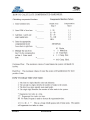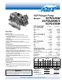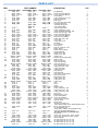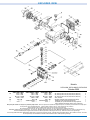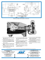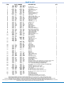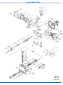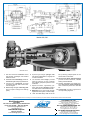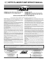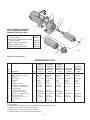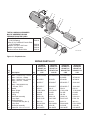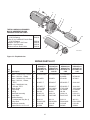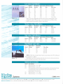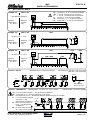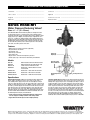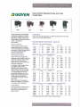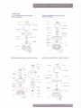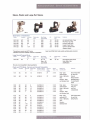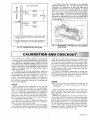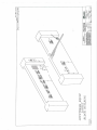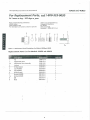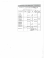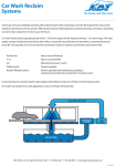
1
OWNER’S MANUAL
OASIS CAR WASH SYSTEMS
800-892-3537 · www.oasiscarwashsystems.com
Installation
Revised 04/01/08
1.3
Installation
Revised 04/01/08
1.5
Installation
Revised 04/01/08
1.4
REVERSE OSMOSIS OPERATION
Once your Oasis RO System is on-line, the day to day operation is very simple.
You should check the salt level in the brine tank daily and add salt as required. Once per week test to ensure the
water is free of chlorine. This can be checked from the test cock located on top of the carbon filter. You should
also check the water for hardness to ensure the proper operation of the water softener. Water must be at zero grains
hardness. During normal operation, the system will operate automatically and does not require any further
attention.
The Oasis RO System is basically two systems in one. The first system produces pure water. The other system
delivers the pure water to the wash bays.
RO MEMBRANE SYSTEM
The RO Membrane is nothing more than a very fine filter. This filter (membrane) is so fine that it simply removes
the minerals from the water and allows only the pure water to pass (permeate) through the membrane.
Since the membrane is so fine, a pump must be used to pressurize the water to approximately 200 PSI to force the
water through the membrane. As with any filter, after time the membrane could become clogged (fouled) with
minerals, grease or dirt and not allow any further passage of the pure water through the membrane and into the
holding tank. Since the membranes are very fine and fouling can occur, a water softener is used to soften the
incoming water and the carbon filter is used to remove the chlorine. Chlorine will damage the membrane, and
prolonged exposure can cause permanent damage.
To keep fouling from happening, a certain amount of water must be used to flush past the surface of the membrane
and rinse the build-up of minerals from the membrane surface. This water is then recirculated through the
membrane pump system and used over. After several passes by the membrane, the recirculating water becomes
very saturated with minerals. It must therefore be discarded. To ensure smooth continuous operation, an orifice is
located in the recirculation system and a controlled amount of water is rejected from the system to drain (reject
water) on a continuous basis as long as the membrane pump is running. The amount of reject water is controlled by
the orifice located in the plumbing in the lower portion of panel. See schematic for its location. The amount of
reject water is set at the factory and should only be changed after consultation with the factory. The amount of
water going to drain can be monitored in the REJECT WATER FLOW METER.
The pure water (PRODUCT WATER) that permeates through the membrane is then stored in the stainless steel
product water holding tank. As the water level reaches the top of the tank a float switch will shut off the membrane
pump, thus stopping the production of pure water. Once the water level is reduced a sufficient amount, the float
switch will start the membrane pump and once again fill the tank with pure water.
If you operate the Oasis system 24 hours per day you will find that the water softener will regenerate at
approximately 2 o'clock AM. The system will receive city water to the Oasis system during the time that the water
softener regeneration takes place. This should be avoided. Do not allow the storage system to run at this time, as
it will cause membrane damage. The normal regeneration time is about 2 hours. You may wish to check the
softener manual for more detailed information concerning the operation of the water softener.
DELIVERY SYSTEM OPERATION
The Delivery System consists of a pump capable of producing pressure up to approximately 150 PSI using the water
from the pure water holding tank. The electric control panel and wash bay switches control the pump.
Should the water level fall below the low water level switch in the water holding tank, the delivery pump shuts off
until the water level is restored.
INSTALLATION & OPERATION INSTRUCTIONS
This Oasis RO system is pre-plumbed and wired for easy installation and start-up. Once this system is on-line, very
little preventative maintenance is required.
1. Chlorine test weekly. The chlorine level should remain at zero to prevent permanent damage to the RO
Membranes.
2. Water hardness test weekly. The water hardness should remain at zero, to prevent premature fouling of the RO
Membranes.
3. Sediment filter checked weekly (visual inspection).
INSTALLATION
1. Select a location where the required utilities are easily accessible.
2. Check the incoming water pressure prior to installing the RO System. Should the water pressure be less than 40
PSI, a booster pump may be required (consult factory). If the incoming water pressure exceeds 100 PSI it will be
necessary to install a pressure-reducing valve.
3. Normal electrical requirements for this system are 240/480 volt 3-phase 10/20-amp service. Controls are located
in the main electrical enclosure.
4. Make the drain line connection (1/2 inch) to a floor drain near the RO system. Should a drain not be available in
close proximity to the RO system, you can run the drain line overhead to a drain located elsewhere in the building
(Max height 8' above base). Please refer to sketch for the location of this connection.
5. The final connection to make is the pure water connection from each wash bay to the RO manifold located on the
upper right end of JETSTREAM MODULE.
START UP INSTRUCTIONS
1.
2.
3.
4.
5.
6.
7.
8.
9.
10.
11.
12.
13.
14.
15.
16.
17.
18.
19.
20.
21.
22.
23.
24.
Charging the system with water is the first step in starting up the RO system. Check to be sure that the
manual service valve is in the off position (customer supplied).
Make sure the power is turned off.
Install a temporary jumper wire between terminal number 5 and number 76 (solenoid valve).
Remove sediment filter and housing, being careful to not lose the o-ring.
Turn off the 3-phase contactor for RO storage pump.
Turn on the power to control panel.
Partially open the service valve to flush the dust out of the charcoal tank. If this step is skipped, you may
cause the sediment filter to foul prematurely.
Allow charcoal filter to flush slowly for approximately fifteen minutes.
Close the service valve therefore shutting off the water supply, turn off control power and then remove the
jumper between terminal number 5 and number 76.
Reinstall the sediment filter and housing.
Turn on control power.
Caution! Make sure water softeners have been regenerated before charging system (water should test 0
grains hardness).
Make sure the ½” permeate pure water hose is connected to the bottom plumbing of the pure water holding
tank.
Turn off the RO 3-Phase contactor. This will enable the storage pump and allow water to flow and expel
all air from the system (air bubbles can be seen through flow meters on front door).
The upper float switch in the pure water holding tank must be in the down position.
Turn on the service valve slowly, checking for air bubble again in flow meters.
Now check pump for correct rotation by watching shaft (may seen at about mid position of storage
pump), while someone else bumps RO pump contactor momentarily.
See pump for correct rotation. CAUTION! Do not run pump for more than 5 seconds in the event rotation
is wrong, as this can cause sever damage to the pump. When the rotation is correct, the PUMP
CONTACTOR can now be turned to run position. The high-level float switch must be in the down position
for the pump to run. There is about an 8 second delay before the pump will start.
Once the system is producing water, adjust the pressure to about 200 PSI. See Schematic for pressure
regulator location.
Water should begin to fill the pure water holding tank
Make sure the high-level float switch will shut the system down automatically. Manually raise this switch
by hand, which should shut down the system. Again lower the high-level float switch and the system will
restart after the 8-second delay.
While the storage tank is filling, use the water test kits. Take a sample of water from the water sample
valve and check for chlorine and hardness. It is extremely important that the RO membrane(s) be supplied
with chlorine-free, soft water. Both of the readings should be zero. If they are not, discard the water in the
storage tank until the water becomes pure.
After the storage tank has filled with pure water, make sure the hand valve in the supply line to the delivery
pump from the storage tank is fully open.
The RO System is now in full automatic operation.
TROUBLE SHOOTING GUIDE
1) Product flow is less than normal, pressure normal and water with water temperature at
approximately 78 deg F
* CAUSE:
RO membrane(s) fouled.
* SOLUTION:
Membrane(s) should be cleaned. CONSULT FACTORY.
2) Product flow higher than normal and pressure normal with water temperature at
approximately 78 deg F
* CAUSE:
Membrane(s) damaged.
* SOLUTION:
Repair or replace. The membrane life is approximately three to five years depending on service
duty.
3) Storage pump will not start.
* CAUSE:
a) Control panel circuit breaker has tripped.
b) Motor overload has tripped.
c) Float switch is stuck or defective.
d) Motor has become defective.
e) High-level float switch is stuck or defective.
* SOLUTION:
a) Reset circuit breaker.
b) Reset motor overload.
c) Repair or replace.
d) Repair or replace.
e) Repair or replace.
5) Delivery pump will not start.
* CAUSE:
a) Control panel circuit breaker has tripped.
b) Motor overload has tripped.
c) Motor has become defective.
d) Pressure switch is not working.
e) Low water level in holding tank.
f) Low-water switch is defective.
* SOLUTION:
a) Reset circuit breaker.
b) Reset motor overload.
c) Repair or replace.
e) Repair or replace.
6) No delivery pressure.
* CAUSE:
a) See step number 5.
b) Insufficient amount of water in storage tank.
c) Delivery pump is damaged.
d) Pump is running in the wrong direction.
* SOLUTION:
a) See step number 5.
b) Allow time for tank to fill.
c) Repair or replace pump.
d) Change motor rotation if required, at time
of installation only.
7) No storage pressure.
* CAUSE:
a) Low incoming water pressure.
b) Float switch is defective.
c) Lost power to pump.
d) Pump is running in the wrong direction.
e) Motor has become defective.
f) System water leaks.
* SOLUTION:
a) Incoming water pressure should be between 40 and 100 PSI.
b) Repair or replace.
c) Replace fuse or reset overload.
d) Change motor rotation if required at time of installation only.
f) Repair or replace.
g) Repair or replace failed plumbing.
8) Storage pump short cycles on and off.
* CAUSE:
a) Sediment filter dirty.
b) Insufficient water flow/pressure.
* SOLUTION:
a) Replace.
b) Check incoming water supply (40-100 PSI required).
DLA9, DLA12, DLA16, DLA26
Operating instructions
Combination contactor - motor circuit-breaker
FPTC 407714 P0001-07/97
ABB Control Inc.
23
AC 1000.6 – 7/98
15 lb.in.
9 lb.in.
9 lb.in.
Warning ! The operation, installation and servicing of this appliance must be carried out by a qualified electrician applying the relevant rules of the art, installation standards and safety regulations. Before operating
the contactors, check that control voltage complies with the data on the coil mounting bracket. Connection to other control voltage can destroy the coil. Do not touch live parts. Danger !.
24
AC 1000.6 – 7/98
ABB Control Inc.
®
5CP Plunger Pump
5CP2120W
5CP2140WCS
5CP2150W
Models
SPECIFICATIONS
MODEL 5CP2120W
FEATURES
Superior Design
●
●
●
●
●
●
Triplex plunger design gives smoother liquid flow.
Hi-Pressure Seals are completely lubricated and cooled by
the liquids being pumped.
Inlet and discharge valve assemblies interchange for easier
maintenance.
Lubricated Lo-Pressure Seals provides double protection against
external leakage.
Oil bath crankcase assures optimum lubrication.
Close tolerance concentricity of the ceramic plunger maximizes
seal life.
Quality Materials
●
●
●
●
●
●
●
●
Precision design 304 stainless steel valves and seats are hardened
and polished for ultimate seating and extended valve life.
Forged brass manifolds for strength and corrosion resistance.
Special blend W770 manifold offers washout and freeze protection
for car wash applications.
Special concentric, high-density, polished, solid ceramic plungers
provide a true wear surface and extended seal life.
Specially formulated, CAT PUMP exclusive, Hi-Pressure Seals offer
unmatched performance and seal life.
Die cast aluminum crankcase provides high strength, minimum
weight and precision tolerance control.
Chrome-moly crankshaft gives unmatched strength and surface
hardness.
Oversized crankshaft bearings with greater loading capacity mean
longer bearing life.
U.S. Measure
Metric Measure
Flow ...............................................................4.0 GPM
Pressure Range......................................100-2500 PSI
RPM ..............................................................950 RPM
Bore....................................................................0.787"
Stroke .................................................................0.709"
Weight ...........................................................19.14 lbs.
(15 L/M)
(7-175 BAR)
(950 RPM)
(20 mm)
(18 mm)
(8.7 kg)
MODEL 5CP2140WCS
Flow ...............................................................4.0 GPM
Pressure Range......................................100-2500 PSI
RPM ............................................................1725 RPM
Bore....................................................................0.787"
Stroke .................................................................0.394"
Weight ...........................................................19.14 lbs.
MODEL 5CP2150W
Flow ...............................................................5.0 GPM
Pressure Range.......................................100-2000 PSI
RPM ............................................................1725 RPM
Bore....................................................................0.787"
Stroke .................................................................0.472"
Weight ...........................................................19.14 lbs.
●
●
●
Convenient “press-in” style seal case for ease in servicing.
Wet-end is easily serviced without entering crankcase, requiring less
time and effort.
Valve assemblies are accessible without disturbing piping, for quick
service.
Preset packings mean no packing gland adjustment is necessary,
reducing maintenance costs.
Inlet Pressure Range (950 RPM) .............– 5 to 60 PSI
Inlet Pressure Range (1725 RPM) ...Flooded to 60 PSI
Crankcase Capacity ............................................17 oz.
Max. Liquid Temperature ....................................160°F
WARNING
(– 0.35 to 4 BAR)
(Flooded to 4 BAR)
(0.51 L)
(71°C)
Above 130°F call CAT PUMPS for inlet conditions and elastomer recommendations.
Inlet Ports (2)................................................1/2" NPTF
Discharge Ports (2) ......................................3/8" NPTF
Shaft Diameter....................................................0.787"
Dimensions ....................................10.35 x 10.0 x 5.78"
(1/2" NPTF)
(3/8" NPTF)
(20 mm)
(263 x 254 x 147 mm)
ELECTRIC HORSEPOWER REQUIREMENTS
MODEL
FLOW
U.S.
GPM
2120W
4.0
Alternate 5.0
2140WCS 4.0
2150W
5.0
L/M
15
19
15
19
DETERMINING
THE PUMP R.P.M.
All systems require both a primary pressure regulating device (i.e., regulator, unloader) and
a secondary pressure safety relief device (i.e., pop-off valve, safety valve). Failure to
install such relief devices could result in personal injury or damage to the pump or to
system components. CAT PUMPS does not assume any liability or responsibility for the
operation of a customer’s high pressure system.
(19 L/M)
(7-140 BAR)
(1725 RPM)
(20 mm)
(12 mm)
(8.7 kg)
COMMON SPECIFICATIONS
Easy Maintenance
●
(15 L/M)
(7-175 BAR)
(1725 RPM)
(20 mm)
(10 mm)
(8.7 kg)
DETERMINING
THE REQUIRED H.P.
DETERMINING
MOTOR PULLEY SIZE
PRESSURE
MOTOR PULLEY SIZE
PSI
PSI
PSI
PSI Using 1725 RPM Motor
1200 1500 2000 2500 & 8" Std. Pump Pulley
BAR BAR BAR BAR
RPM
Pulley
85
105
140
175
O.D.
3.3
4.1
5.5
6.9
950
4.3
4.1
5.1
6.9
N/A
1188
5.5
3.3
4.1
5.5
6.9
1725
Direct
4.1
5.1
6.9
N/A
1725
Direct
Rated G.P. M.
Rated R.P. M.
=
“Desired” G.P. M.
“Desired” R.P. M.
GPM x PSI
1460
=
Electric Brake
H. P. Required
Motor Pulley O.D.
Pump R.P.M.
=
Pump Pulley O.D.
Motor R.P.M.
See complete Drive Packages [Inclds: Pulleys, Belts, Hubs, Key] Tech Bulletin 003.
Refer to pump Service Manual for repair procedure, additional technical information and pump warranty.
“Customer confidence is our greatest asset”
PARTS LIST
ITEM
PART NUMBER
5CP2120W MATL
2
5
8
10
11
15
20
25
30
32
33
37
38
40
48
49
50
51
53
64
65
70
75
88
90
98
99
100
106
120
121
125
139
162
163
164
166
167
168
172
174
185
188
196
250
255
260
30057
96031
126542
46910
14028
43222
14480
48742
46928
—
—
46798
14179
92241
44428
92519
125824
25625
23170
46940
14044
48617
46746
48458
46838
43328
45697
46841
46730
48394
◆ 48432
✝ 48201
46749
43305
45153
◆ 48429
46843
13978
14329
◆ 48904
43307
44936
46667
22179
48361
43358
44938
◆ 48908
43725
43723
43750
44565
17615
15855
◆ 48431
43849
48245
87872
126513
22187
118672
30243
30611
STL
STZP
STCP R
AL
NBR
NBR
STL
TNM
FCM
—
—
—
NBR
—
NBR
STZP
STCP R
STCP
NBR
AL
NBR
AL
CM
BBNP
NBR
S
S
CC
NBR
FPM
EPDM
SSL
PVDF
NBR
FPM
EPDM
BB
NBR
FPM
EPDM
SNG
FPM
HT
BBCP
D
NBR
FPM
EPDM
S
S
S
PVDF
NBR
FPM
EPDM
BBCP
W770
STZP
STCP R
BBCP
STCP
STZP
STZP
5CP2140WCS MATL
30057
96031
126542
46910
14028
43222
14480
48742
—
48203
48224
46798
14179
92241
44428
92519
125824
25625
23170
46940
14044
48617
46746
48458
46838
43328
45697
46841
46730
48394
◆ 48432
✝ 48201
46749
43305
45153
◆ 48429
46843
13978
14329
◆ 48904
43307
44936
46667
22179
48361
43358
44938
◆ 48908
43725
43723
43750
44565
17615
15855
◆ 48431
43849
48245
87872
126513
22187
118672
30243
30611
STL
STZP
STCP R
AL
NBR
NBR
STL
TNM
—
FCM
AL
—
NBR
—
NBR
STZP
STCP R
STCP
NBR
AL
NBR
AL
CM
BBNP
NBR
S
S
CC
NBR
FPM
EPDM
SSL
PVDF
NBR
FPM
EPDM
BB
NBR
FPM
EPDM
SNG
FPM
HT
BBCP
D
NBR
FPM
EPDM
S
S
S
PVDF
NBR
FPM
EPDM
BBCP
W770
STZP
STCP R
BBCP
STCP
STZP
STZP
DESCRIPTION
30057
96031
126542
46910
14028
43222
14480
48742
46982
—
—
46798
14179
92241
44428
92519
125824
25625
23170
46940
14044
48617
46746
48458
46838
43328
45697
46841
46730
48394
◆ 48432
✝ 48201
46749
43305
45153
◆ 48429
46843
13978
14329
◆ 48904
43307
44936
46667
22179
48361
43358
44938
◆ 48908
43725
43723
43750
44565
17615
15855
◆ 48431
43849
48245
87872
126513
22187
118672
30243
30611
STL
STZP
STCP R
AL
NBR
NBR
STL
TNM
FCM
—
—
—
NBR
—
NBR
STZP
STCP R
STCP
NBR
AL
NBR
AL
CM
BBNP
NBR
S
S
CC
NBR
FPM
EPDM
SSL
PVDF
NBR
FPM
EPDM
BB
NBR
FPM
EPDM
SNG
FPM
HT
BBCP
D
NBR
FPM
EPDM
S
S
S
PVDF
NBR
FPM
EPDM
BBCP
W770
STZP
STCP R
BBCP
STCP
STZP
STZP
265
30637 STZP
30659 —
30637 STZP
30659 —
30637 STZP
30659 —
275
30944 STL
30944 STL
30944 STL
283
298
299
300
34334
34970
34980
816650
33628
31628
◆ 31648
31638
—
STZP
STZP
W770
NBR
FPM
EPDM*
HT
34334
34970
34980
816650
33628
31628
◆ 31648
31638
—
STZP
STZP
W770
NBR
FPM
EPDM*
HT
QTY
5CP2150W MATL
34334
34970
34980
816650
33628
31628
◆ 31648
31638
—
STZP
STZP
W770
NBR
FPM
EPDM*
HT
Key (M6x6x25)
Screw, Sems HHC (M8x16)
Screw, Sems HHC (M8x16)
Cover, Bearing
O-Ring, Bearing Cover - 70D
Seal, Oil, Crankshaft
Bearing, Ball
Rod, Connecting Assy [10/01]
Crankshaft, Dual End
Crankshaft, Single End
Cover, Bearing Blind
Cap, Oil Filler, Domed
O-Ring, Oil Filler Cap - 70D
Gauge, Oil, Bubble w/Gasket - 80D
Gasket, Flat, Oil Gauge - 80D
Screw, Sems HHC (M6x16)
Screw, Sems HHC (M6x16)
Plug, Drain (1/4"x19BSP)
O-Ring, Drain Plug - 70D
Cover, Rear
O-Ring, Rear Cover
Crankcase
Pin, Crosshead
Rod, Plunger
Seal, Oil, Crankcase - 70D
Slinger, Barrier
Washer, Keyhole (M18)
Plunger (M20x50)
Washer, Seal - 90D
Washer, Seal - 90D
Washer, Seal
Retainer, Plunger w/Stud (M6)
Retainer, Seal
Seal, LPS w/S-Spg
Seal, LPS w/SS-Spg
Seal, LPS w/SS-Spg
Case, Seal (Press-in-style)
O-Ring, Seal Case - 70D
O-Ring, Seal Case
O-Ring, Seal Case
Seal, HPS w/S
Seal, HPS w/SS
Seal, HPS 2-Pc w/S-Support
Plug, Inlet (1/2"NPT)
Back-up-Ring, Seat
O-Ring, Seat - 70D
O-Ring, Seat - 70D
O-Ring, Seat
Seat
Valve
Spring
Retainer, Spring
O-Ring, Valve Plug - 75D
O-Ring, Valve Plug - 70D
O-Ring, Valve Plug - 75D
Plug, Valve
Manifold, Head - W770
Screw, HSH (M8x70)
Screw, HSH (M8x70)
Plug, Discharge (3/8"NPT)
Protector, Shaft
Mount, Direct
Assembly, Angle Rail - B
(Inclds: 28499, 30900, 30910, 30920) (Belt Drive Only)
Mount, Angle Assy-Retro Fit
Kit, Complete Mounting
(Inclds: 30611, 30633, 118672) (Belt Drive Only)
Hub & Key Assy (M20 w/M6 Keyway)
[See Drive Packages, Tech Bulletin 003]
Kit, Oil Drain
Clutch, Assy, Single Groove, 20mm, 12VDC
Clutch, Assy, Dual Groove, 20mm, 12VDC
Head, Complete
Kit, Seal (Inclds: 98, 106, 121, 125)
Kit, Seal (Inclds: 98, 106, 121, 125)
Kit, Seal (Inclds: 98, 106, 121, 125)
Kit, Seal (Inclds: 98, 106, 121, 125)
1
8
8
2/1
2
2
2
3
1
1
1
1
1
1
1
4
4
1
1
1
1
1
3
3
3
3
3
3
3
3
3
3
3
3
3
3
3
3
3
3
3
3
3
1
6
6
6
6
6
6
6
6
6
6
6
6
1
8
8
1
1
1
1
1
1
1
1
1
1
1
1
1
1
1
EXPLODED VIEW
Models
5CP2120W, 5CP2140WCS, 5CP2150W
October 2006
5CP2120W MATL
310
350
400
—
—
30821
31821
◆ 31162
30696
7850
—
6107
NBR
FPM
EPDM
STZP
BB
—
—
5CP2140WCS MATL
30821
31821
◆ 31162
30696
7850
8026ES-8042ES
6107
5CP2150W MATL
NBR
30821
FPM
31821
EPDM
◆ 31162
STZP
30696
BB
7850
—
8026ES-8042ES
—
6107
NBR
FPM
EPDM
STZP
BB
—
—
Kit, Valve (Inclds: 162,163,164,166,167,168,172)
Kit, Valve (Inclds: 162,163,164,166,167,168,172)
Kit, Valve (Inclds: 162,163,164,166,167,168,172)
Plier, Reverse
Modular Unloader (See Individual Data Sheet)
BD Motors (See Individual Data Sheet)
Oil, Bottle (21 oz) ISO 68 Multi-viscosity Hydraulic
(Fill to specified crankcase capacity prior to start-up)
2
2
2
1
1
1
1
Bold print part numbers are unique to a particular pump model. Italics are optional items. ◆ Silicone oil/grease required. ✝ Production parts are different than repair parts.
R Components comply with RoHS Directive. [ ] Date of latest production change. W770 effective with 97 production.
*Review material codes for individual items (HT generally may be used as alternate).
See Tech Bulletins 002, 003, 024, 036, 043, 053, 060, 061, 064, 073, 074, 077, 078 and 083 for additional information.
MATERIAL CODES (Not Part of Part Number): AL=Aluminum BB=Brass BBCP=Brass/Chrome Plated BBNP=Brass/Nickel Plated CC=Ceramic CM=Chrome-moly
D=Acetal EPDM=Ethylene Propylene Diene Monamer FBB=Forged Brass FCM=Forged Chrome-moly FPM=Fluorocarbon HS=High Strength
HT=Hi-Temp (EPDM Alternative) NBR=Medium Nitrile (Buna-N) PVDF=Polyvinylidene Fluoride S=304SS SNG=Special Blend (Buna) SSL=316SS/Low Carbon STL=Steel
W770=Special Alloy STCP=Steel/Chrome Plated STZP=Steel/Zinc Plated TNM=Special High Strength
Models 5CP2120W, 5CP2140WCS, 5CP2150W
10
1
9
3
4
5
6
11
7
12
2
8
10
1
2
3
4
5
Die cast aluminum crankcase means
high strength, lightweight, and excellent
tolerance control.
Oversized crankshaft bearings provide extended bearing life and pump performance.
Chrome-moly crankshaft provides
unmatched strength and surface hardness for long life.
Matched high strength connecting rods
noted for strength and superior bearing
quality.
The plunger rods with hardened surfaces
offer wear resistance and Zamak crossheads for high load capacity.
6
7
8
9
The stainless steel slinger provides
back-up protection for the crankcase
seal, keeping pumped liquids out of the
crankcase.
Special concentric, high-density, polished,
solid ceramic plungers provide a true
wear surface and extended seal life.
Manifolds are a high tensile strength
forged W770 alloy for long term, continuous
duty.
100% wet seal design adds to service life
by allowing pumped liquids to cool and
lubricate on both sides.
10 Stainless steel valves, seats and springs
provide corrosion-resistance, ultimate
seating and extended life.
11 Specially formulated, CAT PUMP exclusive, Hi-Pressure Seals offer unmatched
performance and seal life.
12 Press-in style seal case offers alignment
and support for seals and “no tools”
servicing.
Products described hereon are covered by one or more of the following U.S. patents 3558244, 3652188, 3809508, 3920356, 3930756 and 5035580
CAT PUMPS (U.K.) LTD.
World Headquarters
CAT PUMPS
1681 - 94th Lane N.E. Minneapolis, MN 55449 - 4324
Phone (763) 780-5440 — FAX (763) 780-2958
e-mail: [email protected]
www.catpumps.com
1 Fleet Business Park, Sandy Lane, Church Crookham
FLEET, Hampshire, GU52 8BF, England
Phone Fleet 44 1252-622031 — Fax 44 1252-626655
e-mail: [email protected]
N.V. CAT PUMPS INTERNATIONAL S. A.
The Pumps with Nine Lives
Heiveldekens 6A, B-2550 Kontich, Belgium
Phone 32- 3- 450.71.50 — Fax 32-3- 450.71.51
e-mail: [email protected] www.catpumps.be
International Inquiries
CAT PUMPS DEUTSCHLAND GmbH
FAX (763) 785-4329
e-mail: [email protected]
Buchwiese 2, D-65510 Idstein, Germany
Phone 49 6126-9303 0 — Fax 49 6126-9303 33
e-mail: [email protected] www.catpumps.de
PN 993100 Rev D 9618
CP PLUNGER PUMP SERVICE MANUAL
®
3CP MODELS: 3CP1120, 3CP1130, 3CP1140
5CP MODELS: 5CP2120W, 5CP2140WCS, 5CP2150W, 5CP3120, 5CP3120G1, 5CP3130G1,
5CP5120, 5CP5150G1, 5CP6120, 5CP6120G1, 5CP6140, 5CP6150
7CP MODELS: 7CP6170
INSTALLATION AND START-UP INFORMATION
Optimum performance of the pump is dependent upon the entire liquid system and will be obtained only
with the proper selection, installation of plumbing, and operation of the pump and accessories.
SPECIFICATIONS: Maximum specifications refer to individual attributes. It is not
implied that all maximums can be performed simultaneously. If more than one
maximum is considered, check with your CAT PUMPS supplier to confirm the
proper performance and pump selection. Refer to individual pump Data Sheet for
complete specifications, parts list and exploded view.
LUBRICATION: Fill crankcase with special CAT PUMP oil per pump specifications
(3CP-10 oz., 5CP-17 oz., 7CP-38 oz.). DO NOT RUN PUMP WITHOUT OIL IN
CRANKCASE. Change initial fill after 50 hours running period. Thereafter, change
oil every 3 months or 500 hour intervals. Additional lubrication may be required
with increased hours of operation and temperature.
PUMP ROTATION: Pump was designed for forward rotation to allow optimum
lubrication of the crosshead area. Reverse rotation is acceptable if the crankcase oil
level is increased slightly above center dot to assure adequate lubrication.
PULLEY SELECTION: Select size of motor pulley required to deliver the desired
flow from Horsepower Requirement and Pulley Selection Chart (refer to Tech
Bulletin 003 or individual Data Sheet).
DRIVE SELECTION: The motor or engine driving the pump must be of adequate
horsepower to maintain full RPM when the pump is under load. Select the electric
motor from the Horsepower Requirement Chart according to required pump
discharge flow, maximum pressure at the pump and drive losses of approximately
3-5%. Consult the manufacturer of gas or diesel engine for selection of the proper
engine size.
MOUNTING: Mount the pump on a rigid, horizontal surface in a manner to permit
drainage of crankcase oil. An uneven mounting surface will cause extensive
damage to the pump base. To minimize piping stress, use appropriate flexible
hose to inlet and discharge ports. Use the correct belt; make sure pulleys are
aligned. Excessive belt tension may be harmful to the bearings. Hand rotate pump
before starting to be certain shaft and bearings are free moving.
LOCATION: If the pump is used in extremely dirty or humid conditions, it is
recommended pump be enclosed. Do not store or operate in excessively high
temperature areas or without proper ventilation.
INLET CONDITIONS: Refer to complete Inlet Condition Check-List in this manual
before starting system. DO NOT STARVE THE PUMP OR RUN DRY. Temperatures
above 130°F are permissible. Add 1/2 PSI inlet pressure per each degree F over
130°F. Elastomer or RPM changes may be required. See Tech Bulletin 002 or call
CAT PUMPS for recommendations.
C.A.T.: Installation of a C.A.T. (Captive Acceleration Tube) is recommended in
applications with stressful inlet conditions such as high temperatures, booster pump
feed, long inlet lines or quick closing valves.
DISCHARGE CONDITIONS: OPEN ALL VALVES BEFORE STARTING SYSTEM to
avoid deadhead overpressure condition and severe damage to the pump or system.
Install a Pulsation Dampener on the discharge head or in the discharge line as
close to the head as possible. Be certain the pulsation dampener (Prrrrr-o-lator) is
properly precharged for the system pressure (see individual Data Sheet).
A reliable Pressure Gauge should be installed near the discharge outlet of the high
pressure manifold. This is extremely important for adjusting pressure regulating
devices and also for proper sizing of the nozzle or restricting orifice. The pump is
rated for a maximum pressure; this is the pressure which would be read at the
discharge manifold of the pump, NOT AT THE GUN OR NOZZLE.
Use PTFE thread tape or pipe thread sealant (sparingly) to connect accessories or
plumbing. Exercise caution not to wrap tape beyond the last thread to avoid
tape from becoming lodged in the pump or accessories. This condition will cause a
malfunction of the pump or system.
PRESSURE REGULATION: All systems require both a primary pressure regulating
device (i.e., regulator, unloader) and a secondary pressure safety relief device
(i.e., pop-off valve, safety valve). The primary pressure device must be installed on
the discharge side of the pump. The function of the primary pressure regulating
device is to protect the pump from over pressurization, which can be caused by a
plugged or closed off discharge line. Over pressurization can severely damage the
pump, other system components and can cause bodily harm. The secondary safety
relief device must be installed in-line between the primary device and the pump or
on the opposite side of the manifold head. This will ensure pressure relief of the
system if the primary regulating device fails. Failure to install such a safely device
will void the warranty on the pump.
When the high pressure system is left running with the trigger gun off, the by-pass
liquid can be routed to drain or to the pump inlet. If routed to the pump inlet, the
by-pass liquid can quickly develop excessive heat and result in damage to the
pump. A THERMO VALVE installed in the by-pass line is recommended to protect
the pump. An AUTO SHUT-OFF ASSEMBLY may also be used.
NOZZLES: A worn nozzle will result in loss of pressure. Do not adjust pressure
regulating device to compensate. Replace nozzle and reset regulating device to
system pressure.
PUMPED LIQUIDS: Some liquids may require a flush between operations or before
storing. For pumping liquids other than water, contact your CAT PUMPS supplier.
STORING: For extended storing or between use in cold climates, drain all pumped
liquids from pump and flush with antifreeze solution to prevent freezing and
damage to the pump. DO NOT RUN PUMP WITH FROZEN LIQUID (refer to Tech
Bulletin 083).
WARNING
All systems require both a primary pressure regulating device (i.e., regulator, unloader) and a secondary pressure safety relief device (i.e., pop-off valve, safety valve).
Failure to install such relief devices could result in personal injury or damage to the pump or to system components. CAT PUMPS does not assume any liability or responsibility
for the operation of a customer’s high pressure system.
Products described hereon are covered by one or more of the following U.S. patents 3558244, 3652188, 3809508, 3920356, 3930756 and 5035580
CAT PUMPS (U.K.) LTD.
World Headquarters
CAT PUMPS
1681 - 94th Lane N.E. Minneapolis, MN 55449 - 4324
Phone (763) 780-5440 — FAX (763) 780-2958
e-mail: [email protected]
www.catpumps.com
®
The Pumps with Nine Lives
1 Fleet Business Park, Sandy Lane, Church Crookham
FLEET, Hampshire, GU52 8BF, England
Phone Fleet 44 1252-622031 — Fax 44 1252-626655
e-mail: [email protected]
N.V. CAT PUMPS INTERNATIONAL S. A.
Heiveldekens 6A, B-2550 Kontich, Belgium
Phone 32- 3- 450.71.50 — Fax 32-3- 450.71.51
e-mail: [email protected] www.catpumps.be
International Inquiries
CAT PUMPS DEUTSCHLAND GmbH
FAX (763) 785-4329
e-mail: [email protected]
Buchwiese 2, D-65510 Idstein, Germany
Phone 49 6126-9303 0 — Fax 49 6126-9303 33
e-mail: [email protected] www.catpumps.de
PN 33009 Rev J 7709
All Models
3CP1120, 5CP2120W, 7CP6170
5CP3120, 5CP5120, 5CP5150
Removal of Valve Plugs
Valve Plug and O-Ring
Valve Plug, O-Ring and Back-up Ring
CAUTION: Before commencing with service, shut off drive (electric motor, gas or diesel engine) and turn off water supply to
pump. Relieve all discharge line pressure by triggering gun or opening valve in discharge line.
After servicing is completed, turn on water supply to pump, start drive, reset pressure regulating device and secondary valve, read
system pressure on the gauge at the pump head. Check for any leaks, vibration or pressure fluctuations and resume operation.
SERVICING THE VALVES
1. Remove the hex Valve Plugs (top discharge, bottom inlet).
2. Examine the O-Ring under the plug for cuts or distortion.
Replace if worn. Lubricate new O-Rings before installing.
NOTE: The 5CP3120, 5CP5120 and 5CP5150 have
both an O-Ring and Back-up Ring on the Valve Plug.
3. Grasp Spring Retainer by the tab at the top with a
pliers and remove from each valve chamber. Usually
the valve assembly will remain together while being
removed. To separate the valve assembly, insert a
screw-driver into the side of the Spring Retainer and
press on the back side of the Valve to begin separation, then between the Spring Retainer and Seat to
separate completely. If the valve assembly separates
during removal, remove the Spring and Valve with a
needle nose pliers. With a reverse pliers, remove the
Seat from each valve chamber. Then, with a small
screwdriver, carefully remove the O-Ring at the bottom
of the valve chamber.
NOTE: The 5CP2120W, 5CP6120 and 7CP6170
have an O-Ring and Back-up Ring on each Seat.
4. Examine all valve parts for pitting, gouges or wear and
replace with preassembled Valve Assembly. Service
kit contains Spring Retainers, Springs, Valves, Seats,
Back-up Rings and O-Rings.
NOTE: Inlet and discharge valve parts are interchangeable. Two Valve Kits are needed for complete
valve change.
5. Grasp new Valve Assembly by the tab at the top with a
pliers, immerse in oil and push into each valve chamber. Be certain valve assembly is completely seated in
valve chamber.
NOTE: For certain applications apply liquid gasket
to the o-ring crevices and seal surfaces. See Tech
Bulletin 053 for model identification.
NOTE: EPDM elastomers require Silicone-base
lubricant.
6. Apply Loctite® 242® to the threads of each Valve Plug,
thread into valve port and torque per chart.
3CP1120, 5CP2120W, 7CP6170
5CP3120, 5CP5120, 5CP5150
All Models
Removal of Valve Assembly
Removal of Valve Assembly
Removal of Valve Seat O-Ring
3CP1120, 5CP3120, 5CP5120
5CP2120W, 5CP6120, 7CP6170
All Models
Complete Valve Assembly
Complete Valve Assembly
Removal of Socket Head Screws
SERVICING THE PUMPING SECTION
Disassembly
Reassembly
1. Using an allen wrench, remove the Socket Head
Screws from the Manifold Head.
1. Generally Plungers do not need to be replaced. Clean
plungers and remove any foreign material with a nonabrasive cleaner.
2. Rotate Crankshaft by hand to start separation of
Manifold Head from Crankcase.
3. Insert two flat head screwdrivers on opposite sides to
further separate Manifold Head from Crankcase.
Support the underside of the Manifold Head and tap
lightly with a mallet on the backside of the Manifold
Head.
CAUTION: KEEP MANIFOLD PROPERLY ALIGNED
WITH CERAMIC PLUNGERS WHEN REMOVING TO
AVOID DAMAGE TO THE PLUNGERS.
4. Remove the Seal Retainer from each plunger rod and
examine for wear.
2. Install Seal Retainer over Plungers with small tab facing
down and holes facing forward towards manifold head.
3. Rotate the crankshaft so the two outside plungers are
extended the same distance.
4. Lightly lubricate the Plungers and carefully slide the
Manifold Head onto the Plungers supporting from the
underside. On the high pressure V-Packing models or
larger manifolds, it may be necessary to gently tap
with a soft mallet until the Manifold Head is flush with
the Crankcase.
5. Replace Socket Head Screws and torque per chart.
5. Examine Ceramic Plunger for cracks or scoring. Refer
to SERVICING THE PLUNGERS if replacement is
needed.
3CP1120, 5CP2120W, 5CP6120
5CP3120, 5CP5120, 5CP5150, 7CP6170
All Models except 7CP6170
Seal Arrangement
Seal Arrangement
Plunger Arrangement
SERVICING THE PLUNGERS
Disassembly
1. To service the plungers, it is necessary to remove the
manifold head. Follow disassembly procedure for
SERVICING THE PUMPING SECTION.
2. Remove the Seal Retainer from each plunger rod.
3. Using a wrench, loosen the Plunger Retainer about
three to four turns.
4. Push the Ceramic Plunger back towards the
crankcase to separate from the Plunger Retainer and
proceed with unthreading the Plunger Retainer by
hand.
5. Remove the Plunger Retainer, Seal Washer, Ceramic
Plunger, Keyhole Washer and Barrier Slinger from
each Plunger Rod.
6. On the model 7CP6170 remove the Plunger Retainer,
Stud, Gasket, O-Ring, Back-up Ring, Ceramic Plunger
and Barrier Slinger from each Plunger Rod.
Reassembly
1. Visually inspect Crankcase Oil Seals for deterioration
or leaks and contact factory for assistance with
replacement.
2. Replace Barrier Slinger if damaged and slide onto
Plunger Rod with concave side away from
Crankcase.
3. Examine Seal Washer for cuts or wear and replace as
needed.
4. On the model 7CP6170 examine Gaskets, O-Rings
and Back-up Rings for cuts or wear and replace as
needed.
5. Examine Plunger Retainers and Studs for wear or
damaged threads and replace as needed.
6. On the model 7CP6170 install Gaskets first, then
O-Rings and Back-up Rings onto the Plunger
Retainer.
NOTE: Lubricate O-Rings and Back-up Rings for
ease in installation and to reduce possible damage.
7. All other models, lubricate and install Seal Washer
onto Plunger Retainer.
8. On the model 7CP6170 apply Loctite® 242® to one end
of threaded Plunger Retainer Stud and secure to
Plunger Retainer.
9. Examine Ceramic Plungers for scoring, scale build-up,
chips or cracks and replace as needed. Generally the
ceramic plungers do not need to be replaced.
10. Slide Plunger Retainer Assembly into flat end of
Ceramic Plunger.
11. Apply Loctite ® 242 ® to exposed threaded end of
Plunger Retainer.
12. Install Ceramic Plunger with Plunger Retainer onto
each Plunger Rod shoulder and thread Plunger Rod.
Torque to specifications per chart.
NOTE: Ceramic Plungers can only be installed in
one direction. Counterbore end of Ceramic
Plunger to fit over Plunger Rod shoulder.
13. Install Seal Retainers with small tabs facing down and
holes facing forward towards manifold head.
14. Proceed with servicing the seals or remounting of
Manifold Head as described.
SERVICING THE SEALS AND V-PACKINGS
Disassembly
V-Packing Models:
1. Remove the Manifold Head as described in SERVICING
THE PUMPING SECTION.
1. Lubricate each seal chamber in manifold head.
2. Place the Crankcase side of manifold facing up and
with a reverse pliers, remove the Lo-Pressure Seal
from the Seal Case.
3. Using a reverse pliers, remove the press-in style Seal
Case from the Manifold Head.
4. Remove the O-Ring from O.D. of Seal Case.
Hi-Pressure Seal
Models 3CP1120, 3CP1130, 3CP1140,
5CP2120W, 5CP2140WCS, 5CP2150W,
5CP6120, 5CP6120GI
The Hi-Pressure Seal is generally easily removed from
the manifold without any tools. If extremely worn, a reverse pliers may be used.
V-Packing
Models 5CP3120, 5CP3120G1, 5CP3130G1,
5CP5120, 5CP5150G1, 7CP6170
The V-Packings and Male Adapter are easily removed
from the manifold without any tools.If extremely worn,
a reverse pliers may be used.
Reassembly
NOTE: If your pump has been built with special
seals and O-Rings, service with same type. Refer
to pump Data Sheet for correct parts or kits.
Hi-Pressure Seal Models:
NOTE: For certain applications apply liquid gasket
to the O-Ring crevices and seal surfaces. See Tech
Bulletin 053 for model identification.
NOTE: EPDM elastomers require silicone-base
lubricant.
2. Insert Male Adapter with notches down and “v” side
up and press completely into each seal chamber by
hand.
3. Lubricate V-Packings and install one at a time with
grooved side down into each seal chamber.
4. Examine Seal Case O-Ring and replace if worn.
Lubricate new O-Rings before installing.
5. Press Seal Case into each seal chamber until completely
seated.
Lo-Pressure Seal-All Models:
1. Examine Lo-Pressure Seals for wear to the internal
ridges, outer surfaces or for broken springs and replace as needed.
2. Install Lo-Pressure Seal into Seal Case with garter
spring down.
3. All Models: Install Seal Retainer over Plungers with
small tabs facing down and holes facing forward
towards manifold head.
4. Replace Manifold Head onto pump as described under
SERVICING THE PUMPING SECTION and torque per
chart.
1. Lubricate each seal chamber in manifold head.
NOTE: For certain applications apply liquid gasket
to the O-Ring crevices and seal surfaces. See Tech
Bulletin 053 for model identification.
NOTE: EPDM elastomers require silicone-base
lubricant.
2. Carefully square Hi-Pressure Seal into position by
hand with the grooved side down (metal back facing
out) and press into each seal chamber until completely
seated.
3. Examine Seal Case O-Rings and replace if worn.
Lubricate new O-Ring before installing.
4. Press the Seal Case into each seal chamber until
completely seated.
SERVICING THE CRANKCASE SECTION
1. While Manifold Head, Plungers and Seal Retainers are
removed, examine Crankcase Oil Seals for leaking
and wear.
2. Check for any signs of leaking at Rear Cover, Drain
Plug, Bubble Gauge and Dipstick (7CP6170).
3. Check oil level and for evidence of water in oil.
Change crankcase oil on a regular schedule. See
Preventative Maintenance Check-List.
4. Rotate Crankshaft by hand to feel for smooth bearing
movement.
5. Examine Crankshaft Oil Seal externally for drying,
cracking or leaking.
6. Contact CAT PUMPS or your local distributor if
crankcase service is evidenced.
Loctite and 242 are registered trademarks of the Henkel Corporation.
INLET CONDITION CHECK-LIST
PREVENTATIVE MAINTENANCE CHECK-LIST
Check
Daily Weekly 50 hrs. 500 hrs.* 1500 hrs.** 3000 hrs.**
Clean Filters
x
Oil Level/Quality
x
Oil Leaks
x
Water Leaks
x
Belts, Pulley
x
Plumbing
x
Initial Oil Change
x
Oil Change
x
Seal Change
x
Valve Change
x
Accessories
x
* If other than CAT PUMPS special cutstom-blend multi-viscosity ISO68
hydraulic oil is used, change cycle should be every 300 hours.
** Each system’s maintenance cycle will be exclusive. If system performance decreases, check immediately. If no wear at 1500 hours, check
again at 2000 hours and each 500 hours until wear is observed. Valves
typically require changing every other seal change.
Duty cycle, temperature, quality of pumped liquid and inlet feed
conditions all effect the life of pump wear parts and service cycle.
** Remember to service the regulator/unloader at each seal servicing
and check all system accessories and connections before resuming
operation.
Refer to service DVD for additional assistance.
TORQUE CHART
Pump Item
Pump Model
Torque
in. lbs. ft. lbs. Nm
Thread
Tool Size [P/N]
Plunger Retainer
M6
M10 Hex [25082]
55
4.6 6.2
Manifold Screw
M8
M6 Allen [30941]
115
9.58 13
Valve Plugs
3CP, 5CP
7CP
M22
M26
M24 Hex [44046]
M27 Hex [44045]
870
870
72.5 98
72.5 98
Bearing Cover Screws
3CP
5CP, 7CP
M6
M8
M10 Hex./Phil. [25082]
M13 Hex [25324]
50
115
4.0 5.4
9.58 13
Rear Cover Screws
M6
M10 Hex./Phil. [25082]
50
4.0 5.4
Connecting Rod Screws
M7
M10 Hex [25082}
95
8.0
11
Bubble Oil Gauge
M28 Oil Gauge Tool [44050]
45
3.8
5
Direct Mount Bolts
M8
115
9.58 13
M13 Hex [25324]
TECHNICAL BULLETIN REFERENCE CHART
No.
Subject
002
Inlet Pressure VS Liquid Temperature
Models
All Models
003
Power Unit Drive Packages
3PFR - 68PFR, 10FR - 60FR
024
Lubrication of Lo-Pressure Seals
All Models
036
Cylinder and Plunger Reference Chart
All Models
043
LPS and HPS Servicing
All Plunger Models
060
Baffle Assembly
34170
064
By-Pass Hose Sizing
All Unloaders/Regulators
074
Torque Chart
Piston and Plunger Pumps
077
Oil Drain Kit
All Models (except 2SF/4SF)
078
Field Retrofit Mounting
5CP
083
Winterizing a Pump
All Models
Review Before Start-Up
Inadequate inlet conditions can cause serious malfunctions in the best designed
pump. Surprisingly, the simplest of things can cause the most severe problems or go
unnoticed to the unfamiliar or untrained eye. REVIEW THIS CHECK-LIST BEFORE
OPERATION OF ANY SYSTEM. Remember, no two systems are alike, so there can
be no ONE best way to set-up a system. All factors must be carefully considered.
INLET SUPPLY should exceed the maximum flow being delivered by the pump to
assure proper performance.
❏ Open inlet shut-off valve and turn on water supply to avoid starving pump. DO
NOT RUN PUMP DRY.
❏ Temperatures above 130°F are permissible. Add 1/2 PSI inlet pressure per each
degree F over 130°F. Elastomer or RPM changes may be required. See Tech
Bulletin 002 or call CAT PUMPS for recommendations.
❏ Avoid closed loop systems especially with high temperature, ultra-high pressure
or large volumes. Conditions vary with regulating/unloader valve.
❏ Low vapor pressure liquids, such as solvents, require a booster pump and C. A.T.
to maintain adequate inlet supply.
❏ Higher viscosity liquids require a positive head and a C. A.T. to assure adequate
inlet supply.
❏ Higher temperature liquids tend to vaporize and require positive heads and
C. A.T. to assure adequate inlet supply.
❏ When using an inlet supply reservoir, size it to provide adequate liquid to
accommodate the maximum output of the pump, generally a minimum of 6-10
times the GPM (however, a combination of system factors can change this
requirement); provide adequate baffling in the tank to eliminate air bubbles and
turbulence; install diffusers on all return lines to the tank.
INLET LINE SIZE should be adequate to avoid starving the pump.
❏ Line size must be a minimum of one size larger than the pump inlet fitting. Avoid
tees, 90 degree elbows or valves in the inlet line of the pump to reduce the risk of
flow restriction and cavitation.
❏ The line MUST be a FLEXIBLE hose, NOT a rigid pipe, and reinforced on SUCTION
systems to avoid collapsing.
❏ The simpler the inlet plumbing the less the potential for problems. Keep the
length to a minimum, the number of elbows and joints to a minimum (ideally no
elbows) and the inlet accessories to a minimum.
❏ Use pipe sealant to assure air-tight, positive sealing pipe joints.
INLET PRESSURE should fall within the specifications of the pump.
❏ Acceleration loss of liquids may be increased by high RPM, high temperatures,
low vapor pressures or high viscosity and may require pressurized inlet
and C. A.T. to maintain adequate inlet supply. DO NOT USE C.A.T. WITH
SUCTION INLET.
❏ Optimum pump performance is obtained with +20 PSI (1.4 BAR) inlet pressure
and a C. A.T. for certain applications. With adequate inlet plumbing, most pumps
will perform with flooded suction. Maximum inlet pressure is 60 PSI (4 BAR).
❏ After prolonged storage, pump should be rotated by hand and purged of air to
facilitate priming. Disconnect the discharge port and allow liquid to pass through
pump and measure flow.
INLET ACCESSORIES are offered to protect against over pressurization,
contamination or temperature and control flow.
❏ A shut-off valve is recommended to facilitate maintenance.
❏ Installation of a C. A.T. is essential in applications with stressful conditions such
as high temperatures, booster pump feed or long inlet lines. Do not use C. A.T.
with negative inlet pressure.
❏ A stand pipe can be used in some applications to help maintain a positive head
at the pump inlet line.
❏ Inspect and clean inlet filters on a regular schedule to avoid flow restriction.
❏ A pressure transducer is necessary to accurately read inlet pressure. Short
term, intermittent cavitation will not register on a standard gauge.
❏ All accessories should be sized to avoid restricting the inlet flow.
❏ All accessories should be compatible with the solution being pumped to prevent
premature failure or malfunction.
❏ Optional inlet protection can be achieved by installing a pressure cut off switch
between the inlet filter and the pump to shut off pump when there is no positive
inlet pressure.
BY-PASS TO INLET Care should be exercised when deciding the method of by-pass
from control valves.
❏ It is recommended the by-pass be directed to a baffled reservoir tank, with at
least one baffle between the by-pass line and the inlet line to the pump.
❏ Although not recommended, by-pass liquid may be returned to the inlet line
of the pump if the system is properly designed to protect your pump. When a
pulsation dampener is used, a PRESSURE REDUCING VALVE must be
installed on the inlet line (BETWEEN THE BY-PASS CONNECTION AND THE
INLET TO THE PUMP) to avoid excessive pressure to the inlet of the pump. It is
also recommended that a THERMO VALVE be used in the by-pass line to monitor the temperature build-up in the by-pass loop to avoid premature seal failure.
❏ A reinforced, flexible, low pressure hose rated up to 300 PSI should be used for
routing by-pass back to the pump inlet.
❏ Caution should be exercised not to undersize the by-pass hose diameter and
length. Refer to Technical Bulletin 064 for additional information on the size and
length of the by-pass line.
❏ Check the pressure in the by-pass line to avoid over pressurizing the inlet.
❏ The by-pass line should be connected to the pump inlet line at a gentle angle of
45° or less and no closer than 10 times the pump inlet port diameter e.g. 1-1/2"
port size = 15" distance from pump inlet port.
Handy Formulas to Help You
HOSE FRICTION LOSS
PRESSURE DROP IN PSI PER 100 FT OF HOSE
WITH TYPICAL WATER FLOW RATES
Hose Inside Diameters, Inches
Water*
Flow
Gal/Min
1/4
5/16
3/8
1/2
5/8
3/4
1"
0.5
16
5
2
1
54
20
7
2
2
180
60
25
6
2
3
380
120
50
13
4
2
4
220
90
24
7
3
5
320
130
34
10
4
6
220
52
16
7
1
8
300
80
25
10
2
10
450
120
38
14
3
15
900
250
80
30
7
20
1600
400
121
50
12
25
650
200
76
19
30
250
96
24
40
410
162
42
50
600
235
62
60
370
93
*At a fixed flow rate with a given size hose, the pressure drop across a given hose length
will be directly proportional. A 50 ft. hose will exhibit one-half the pressure drop of a 100
ft. hose. Above values shown are valid at all pressure levels.
WATER LINE PRESSURE LOSS
PRESSURE DROP IN PSI PER 100 FEET
Steel Pipe—Nominal Dia.
Water
GPM
Brass Pipe—Nominal Dia.
1/4 3/8 1/2 3/4 1 11/4 11/2
Copper Tubing O.D. Type L
1/4 3/8 1/2 5/8 3/4 7/8
8.5 1.9
6.0 1.6
120 13 2.9 1.0
30 7.0 2.1
20 5.6 1.8
400 45 10 3.4 1.3
60 14 4.5 1.1
40 11 3.6
94 20 6.7 2.6
1/4 3/8 1/2 3/4
1
2
3
5
8
10
15
25
40
1 1 /4 1 /2
1
1
150 36 12 2.8
100 28 9.0 2.2
230 50 17 6.1 3.0
330 86 28 6.7 1.9
220 62 21 5.2 1.6
500 120 40 15 6.5
520 130 43 10 3.0
320 90 30 7.8 2.4
180 56 22 10
270 90 21 6.2 1.6
190 62 16 5.0 1.5
120 44 20
670 240 56 16 4.2 2.0
470 150 40 12 3.8 1.7
330 110 50
66 17 8.0
39 11 5.0
550 200 88
37
17
23
11
52
29
40
19
210 107
48
61
28
60
80
100
RESISTANCE OF VALVES AND FITTINGS
Nominal
Pipe
Inside
Size
Diameter
Inches
Inches
Equivalent Length of Standard Pipe in Feet
Gate
Valve
Globe
Valve
Angle
Valve
45˚
Elbow
90˚
Elbow
180˚
Close
Ret
Tee
Thru
Run
Tee
Thru
Branch
1/2
3/4
1
11/4
11/2
0.622
0.824
1.049
1.380
1.610
0.41
0.54
0.69
0.90
1.05
18.5
24.5
31.2
41.0
48.0
9.3
12.3
15.6
20.5
24.0
0.78
1.03
1.31
1.73
2.15
1.67
2.21
2.81
3.70
4.31
3.71
4.90
6.25
8.22
9.59
0.93
1.23
1.56
2.06
2.40
3.33
4.41
5.62
7.40
8.63
2
2.067
2.469
3.068
4.026
1.35
1.62
2.01
2.64
61.5
73.5
91.5
120.0
30.8
36.8
45.8
60.0
2.59
3.09
3.84
5.03
5.55
6.61
8.23
10.80
12.30
14.70
18.20
23.90
3.08
3.68
4.57
6.00
11.60
13.20
16.40
21.60
2 1/2
3
4
Arriving at a total line pressure loss, consideration should then be given to
pressure loss created by valves, fittings and elevation of lines.
If a sufficient number of valves and fittings are incorporated in the system to
materially affect the total line loss, add to the total line length, the equivalent
length of line of each valve or fitting.
TYPICAL RESERVOIR TANK
RECOMMENDED 6 TO 10 TIMES SYSTEM CAPACITY
Supply Line
Bypass Line
(from regulator or unloader)
→
D
→
→
→
→
→
MIN. 4"
(Dia of pipe)
T
X
Level Sensing
Device
→
1.5 x D (Min.)
Flexible Hose
to Pump
→
→
FILTER
MIN. 4"
Minimum
Liquid
Level
Bypass Line
(from regulator or
unloader)
Minimum Two Baffles
Sealed at Bottom
Q. How can I find the RPM needed to get specific GPM
(Gallons Per Minute) I want?
Rated RPM
A. Desired RPM = Desired GPM x
Rated GPM
Q. I have to run my pump at a certain RPM. How do I figure
the GPM I’ll get?
Rated GPM
A. Desired GPM = Desired RPM x
Rated RPM
Q. Is there a simple way to find the approximate horsepower
I’ll need to run the pump?
A. Electric Brake
GPM x PSI
=
Horsepower Required
1460
(Standard 85%
Mech. Efficiency)
Q. What size motor pulley should I use?
Pump RPM
A. Pump Pulley (Outer Diameter) x
Motor/Engine RPM
(Consult
Engine Mfr.)
Q. How do I calculate the torque for my hydraulic drive
system?
GPM x PSI
A. Torque (ft. lbs.) = 3.6
RPM
(
)
Avoid Cavitation Damage
One or several of the conditions shown in the chart below may
contribute to cavitation in a system resulting in premature wear,
system downtime and unnecessary operating costs.
CONDITION
Inadequate inlet
line size
Water hammering
liquid acceleration/
deacceleration
Rigid Inlet Plumbing
Excessive Elbows in
Inlet Plumbing
Excessive Liquid
Temperature
SOLUTION
Increase line size to the inlet port or one size
larger
● Install C.A.T. Tube
● Move pump closer to liquid supply
●
Use flexible wire reinforced hose to absorb
pulsation and pressure spikes
● Keep elbows to a minimum and less than 90°
●
Use Thermo Valve in bypass line
Do not exceed pump temperature specifications
● Substitute closed loop with baffled holding tank
● Adequately size tank for frequent or high
volume bypass
● Pressure feed high temperature liquids
● Properly ventilate cabinets and rooms
Air Leaks in Plumbing ● Check all connections
● Use PTFE thread tape or pipe thread sealant
● Size tank according to pump output —
Agitation in Supply
Tank
Minimum 6-10 times system GPM
● Baffle tank to purge air from liquid and
separate inlet from discharge
High Viscosity Liquids ● Verify viscosity against pump specifications
before operation
● Elevate liquid temperature enough to reduce
viscosity
● Lower RPM of pump
● Pressure feed pump
● Increase inlet line size
● Perform regular maintenance or use clean
Clogged Filters
filters to monitor build up
● Use adequate mesh size for liquid and pump
specifications
●
●
DIAGNOSIS AND MAINTENANCE
One of the most important steps in a high pressure system is to establish a regular maintenance program. This will vary slightly with each
system and is determined by various elements such as the duty cycle, the liquid being pumped, the actual specifications vs rated specifications
of the pump, the ambient conditions, the inlet conditions and the accessories in the system. A careful review of the necessary inlet conditions
and protection devices required before the system is installed will eliminate many potential problems.
CAT PUMPS are very easy pumps to service and require far less frequent service than most pumps. Typically, only common tools are required,
making in-field service convenient, however, there are a few custom tools, special to certain models, that do simplify the process. This service
manual is designed to assist you with the disassembly and reassembly of your pump. The following guide will assist in determining the cause
and remedy to various operating conditions. You can also review our FAQ or SERVICE sections on our WEB SITE for more facts or contact
CAT PUMPS directly.
PROBLEM
PROBABLE CAUSE
SOLUTION
Low pressure
•Worn nozzle.
•Belt slippage.
•Air leak in inlet plumbing.
•Pressure gauge inoperative or not registering accurately.
•Relief valve stuck, partially plugged or improperly adjusted.
•Inlet suction strainer (filter) clogged or improperly sized.
•Abrasives in pumped liquid.
•Leaky discharge hose.
•Inadequate liquid supply.
•Severe cavitation.
•Worn seals.
•Worn or dirty inlet/discharge valves.
•Replace with properly sized nozzle.
•Tighten belt(s) or install new belt(s).
•Tighten fittings and hoses. Use PTFE liquid or tape.
•Check with new gauge. Replace worn or damaged gauge.
•Clean/adjust relief valve. Replace worn seats/valves and o-rings.
•Clean filter. Use adequate size filter. Check more frequently.
•Install proper filter.
•Replace discharge hose with proper rating for system.
•Pressurize inlet and install C.A.T.
•Check inlet conditions.
•Install new seal kit. Increase frequency of service.
•Clean inlet/discharge valves or install new valve kit.
Pulsation
•Faulty Pulsation Dampener.
•Foreign material trapped in inlet/discharge valves.
•Check precharge. If low, recharge, or install a new dampener.
•Clean inlet/discharge valves or install new valve kit.
•Worn V-Packings, Hi-Pressure or Lo-Pressure Seals.
•Worn adapter o-rings.
•Humid air condensing into water inside the crankcase.
•Excessive wear to seals and V-Packings.
•Install new seal kit. Increase frequency of service.
•Install new o-rings.
•Install oil cap protector. Change oil every 3 months or 500 hours.
•Install new seal kit. Increase frequency of service.
Knocking noise
•Inlet supply
•Bearing
•Pulley
•Inadequate inlet liquid supply.
•Broken or worn bearing.
•Loose pulley on crankshaft
•Check liquid supply. Increase line size, pressurize or install C.A.T.
•Replace bearing.
•Check key and tighten set screw.
Oil leak
•Crankcase oil seals.
•Crankshaft oil seals and o-rings.
•Drain plug
•Bubble gauge
•Rear cover
•Filler cap
•Worn crankcase oil seals.
•Worn crankshaft oil seals or o-rings on bearing cover.
•Loose drain plug or worn drain plug o-ring.
•Loose bubble gauge or worn bubble gauge gasket.
•Loose rear cover or worn rear cover o-ring.
•Loose filler cap or excessive oil in crankcase.
•Replace crankcase oil seals.
•Remove bearing cover and replace o-rings and/or oil seals.
•Tighten drain plug or replace o-ring.
•Tighten bubble gauge or replace gasket.
•Tighten rear cover or replace o-ring.
•Tighten filler cap. Fill crankcase to specified capacity.
Pump runs extremely rough
•Inlet conditions
•Pump valves
•Pump seals
•Restricted inlet or air entering the inlet plumbing
•Stuck inlet/discharge valves.
•Leaking V-Packings, Hi-Pressure or Lo-Pressure seals.
•Correct inlet size plumbing. Check for air tight seal.
•Clean out foreign material or install new valve kit.
•Install new seal kit. Increase frequency of service.
•Scored plungers.
•Over pressure to inlet manifold.
•Abrasive material in the liquid being pumped.
•Excessive pressure and/or temperature of pumped liquid.
•Running pump dry.
•Starving pump of adequate liquid.
•Replace plungers.
•Reduce inlet pressure per specifications.
•Install proper filtration at pump inlet and clean regularly.
•Check pressure and inlet liquid temperature.
•DO NOT RUN PUMP WITHOUT LIQUID.
•Increase hose one size larger than inlet port size. Pressurize and
install C.A.T.
•Replace manifold. Check liquid compatibility.
Water leak
•Under the manifold
•Into the crankcase
Premature seal failure
•Eroded manifold.
®
7 Frame
Plunger Pump
530
550
Models
SPECIFICATIONS
U.S. Measure
Metric Measure
Flow ...........................................................5.0 GPM
Pressure Range.............................100 to 2500 PSI
RPM .......................................................1100 RPM
Bore..............................................................0.708"
Stroke...........................................................0.945"
(19 L/M)
(7 to 175 BAR)
(1100 RPM)
(18 mm)
(24 mm)
MODEL
FEATURES
Superior Design
●
●
●
●
●
●
Triplex plunger design gives smoother liquid flow.
Hi-Pressure Seals or V-Packings are completely lubricated and
cooled by the liquid being pumped.
Inlet and discharge valve assemblies interchange for easier
maintenance.
Lubricated Lo-Pressure Seals provide double protection against
external leakage.
Oil bath crankcase assures optimum lubrication.
Close tolerance concentricity of the ceramic plunger maximizes
seal life.
Quality Materials
●
●
●
●
●
●
●
●
●
MODEL 550
Flow ...........................................................5.0 GPM
Pressure Range.............................100 to 3000 PSI
RPM .......................................................1415 RPM
Bore..............................................................0.630"
Stroke...........................................................0.945"
(19 L/M)
(7 to 210 BAR)
(1415 RPM)
(16 mm)
(24 mm)
COMMON SPECIFICATIONS
Inlet Pressure Range ..................Flooded to 60 PSI
Crankcase Capacity ......................................25 oz.
Maximum Liquid Temperature .......................160°F
(Flooded to 4 BAR)
(0.75 L)
(71°C)
For temperatures above 130°F call CAT PUMPS for inlet conditions and elastomer recommendations.
Precision design 304 stainless steel valves and seats are hardened
and polished for ultimate seating and extended valve life.
Forged brass manifold is strong and corrosion resistant.
Special concentric, high-density, polished, solid ceramic plungers
provide a true wear surface and extended seal life.
Specially formulated, CAT PUMP exclusive, Hi-Pressure Seals or
V-Packings offer unmatched performance and seal life.
Die cast aluminum crankcase provides high strength, minimum
weight and precision tolerance control.
Chrome-moly crankshaft gives unmatched strength and surface
hardness.
Oversized crankshaft bearings with greater capacity mean longer
bearing life.
Inlet Ports (2) ..........................................1/2" NPTF
(1/2" NPTF)
Discharge Ports (2).................................3/8" NPTF
(3/8" NPTF)
Shaft Diameter ..............................................0.945"
(24 mm)
Weight........................................................25.5 lbs.
(11.5 kg)
Dimensions................................13.6 x 9.61 x 6.41" (346 x 244 x 163 mm)
ELECTRIC HORSEPOWER REQUIREMENTS
MODEL
530
Easy Maintenance
●
530
Wet end is easily serviced without entering crankcase, requiring less
time and effort.
Valve assemblies are accessible without disturbing piping, for quick
service.
Preset packings mean no packing gland adjustment is necessary,
reducing maintenance costs.
WARNING
All systems require both a primary pressure regulating device (i.e., regulator, unloader) and
a secondary pressure safety relief device (i.e., pop-off valve, safety valve). Failure to
install such relief devices could result in personal injury or damage to the pump or to
system components. CAT PUMPS does not assume any liability or responsibility for the
operation of a customer’s high pressure system.
550
FLOW
U.S.
GPM
5.0
4.5
4.0
5.0
4.0
3.0
L/M
19.0
17.0
15.0
19.0
15.0
11.4
DETERMINING
THE PUMP R.P.M.
DETERMINING
THE REQUIRED H.P.
DETERMINING
MOTOR PULLEY SIZE
PRESSURE
PSI PSI PSI
1800 2150 2500
BAR BAR BAR
125 150 175
6.2
7.4
8.6
5.6
6.6
7.7
5.0
5.9
6.9
6.2
7.4
8.6
5.0
5.9
6.9
3.7
4.4
5.2
MOTOR PULLEY SIZE
PSI Using 1725 RPM Motor
3000 & Std. 10" Pulley O.D.
BAR
RPM
Pulley
210
O.D.
N/A
1100
6.3
N/A
990
5.6
N/A
880
5.0
10.3
1415
8.0
8.3
1130
6.4
6.2
850
5.0
Rated G.P. M.
Rated R.P. M.
=
“Desired” G.P. M.
“Desired” R.P. M.
GPM x PSI
1460
=
Electric Brake
H. P. Required
Motor Pulley O.D.
Pump R.P.M.
=
Pump Pulley O.D.
Motor R.P.M.
See complete Drive Packages [Inclds: Pulleys, Belts, Hubs, Key] Tech Bulletin 003.
Refer to pump Service Manual for repair procedure, additional technical information and pump warranty.
“Customer confidence is our greatest asset”
PARTS LIST
ITEM
2
5
8
9
10
11
15
20
25
31
32
33
37
38
40
48
49
50
51
53
56
64
65
69
70
75
88
90
96
97
PART NUMBER
530 MATL
550 MATL
30067
92519
43223
815280
12393
43222
43221
48863
43220
828710
43211
14177
92241
44428
92520
25625
23170
43217
44836
45056
43240
43237
43229
43227
43228
43328
45697
43232
43235
17399
14160
45891
104360
45686
45687
43239
43243
44926
—
45683
20285
11693
43245
44925
—
—
—
—
22179
43248
43249
44383
43722
43825
43721
43824
43751
43823
44564
17617
11691
43851
45417
46868
45550
43633
43256
30243
30645
30611
30660
30206
33000
34334
34628
34630
34959
812183
30488
—
30820
31820
30696
43257
44050
6575
6107
STL
STZP
AL
FBR
NBR
NBR
STL
TNM
FCM
—
ABS
NBR
—
NBR
STZP
STCP
NBR
AL
NBR
AL
POP
CM
ZZCP
STZP
NBR
S
S
CC
PTFE
NBR
FPM
CU
S
PVDF
PVDF
—
NBR
FPM
—
BB
NBR
FPM
SNG
FPM
—
—
—
—
BBCP
PTFE
NBR
FPM
S
S
S
S
S
S
PVDF
NBR
FPM
BBCP
BBCP
S
STZP
BB
STCP
STZP
STZP
STZP
—
F
STL
—
STZP
STZP
STZP
BBCP
NBR
—
NBR
NBR
STZP
STZP
STZP
—
—
30067
92519
43223
815280
12393
43222
43221
48863
43220
828710
43211
14177
92241
44428
92520
25625
23170
43217
44836
45056
43240
43237
43229
43227
43228
43328
45697
43311
43235
17399
14160
45891
104360
45686
45687
43313
43316
—
106660
45684
20285
11693
—
—
43320
43319
46287
43318
22179
43248
43249
44383
43722
—
43721
—
43751
—
44564
17617
11691
43851
45547
46868
45550
43633
43256
30243
30645
30611
30660
30206
33000
34334
34628
34630
34959
812184
30610
31610
30820
31820
30696
43257
44050
6575
6107
STL
STZP
AL
FBR
NBR
NBR
STL
TNM
FCM
—
ABS
NBR
—
NBR
STZP
STCP
NBR
AL
NBR
AL
POP
CM
ZZCP
STZP
NBR
S
S
CC
PTFE
NBR
FPM
CU
S
PVDF
PVDF
—
NBR
—
FPM
BB
NBR
FPM
—
—
BB
PTFE
HT
BB
BBCP
PTFE
NBR
FPM
S
—
S
—
S
—
PVDF
NBR
FPM
BBCP
BBCP
S
STZP
BB
STCP
STZP
STZP
STZP
—
F
STL
—
STZP
STZP
STZP
BBCP
NBR
HT
NBR
NBR
STZP
STZP
STZP
—
—
DESCRIPTION
QTY
Key (M8x7.5x25)
1
Screw, HHC Sems (M6x16)
8
Cover, Bearing
2
Shim, Bearing Cover (2-pc)
1
O-Ring, Bearing Cover
2
Seal, Oil
2
Bearing, Roller
2
Rod, Assy, Connecting [6/02]
3
Crankshaft, Dual End
1
Protector, Oil Cap w/Gasket
1
Cap, Oil Filler
1
O-Ring, Filler Cap - 70D
1
Gauge, Oil, Bubble w/Gasket - 80D
1
Gasket, Flat, Oil Gauge - 80D
1
Screw, HHC Sems (M6x20)
4
Plug, Drain (1/4"x19BSP)
1
O-Ring, Drain Plug - 70D
1
Cover, Rear
1
O-Ring, Rear Cover - 70D
1
Crankcase (M10)
1
Pan, Oil
1
Pin, Crosshead
3
Rod, Plunger
3
Washer, Oil Seal
3
Seal, Oil, Crankcase
3
Slinger, Barrier
3
Washer, Keyhole (M18)
3
Plunger (M18x77 and M16x77)
3
Back-up-Ring, Plunger Retainer
3
O-Ring, Plunger Retainer - 80D
3
O-Ring, Plunger Retainer - 70D
3
98
Gasket, Plunger Retainer
3
99
Retainer, Plunger w/Stud
3
100
Retainer, Seal, Rear
3
Retainer, Seal, Adapter, Front
3
101
Wick, Long Tab
3
106
Seal, LPS w/S-Spg
3
Seal, LPS w/SS-Spg
3
Seal, LPS w/S-Spg
3
120
Case, Seal
3
121
O-Ring, Seal Case - 70D
3
O-Ring, Seal Case
3
125
Seal, HPS w/S
3
Seal, HPS w/SS
3
126
Adapter, Female
3
127
V-Packing
6
V-Packing
6
128
Adapter, Male
3
139
Plug (1/2" NPT)
1
162
Back-up-Ring, Seat
6
163
O-Ring, Seat - 80D
6
O-Ring, Seat - 70D
6
164
Seat, Q.V.
6
Seat, F.V.
6
166
Valve, Q.V.
6
Valve, F.V.
6
167
Spring, Q.V.
6
Spring, F.V.
6
168
Retainer, Spring
6
172
O-Ring, Valve Plug - 90D
6
O-Ring, Valve Plug - 90D
6
174
Plug, Valve
6
185
Head, Manifold (M10F)
1
187
Stud, Manifold (M10x35)
4
194
Nut, Flanged (M10)
4
196
Plug, Discharge (3/8" NPT)
1
250
Protector, Shaft
1
255
Kit, Direct Mounting
1
260
Rail, Angle, Assy A-U.S. (Inclds: 30635 [2.09"], 31129, 990777, 30910, 30920)
1
Rail, Angle, Assy B-U.S. (Inclds: 28499 [2.95"], 30900, 30910, 30920)
1
265
Kit, Mounting (Inclds: 30645, 30206, 33000, 30067, 43256)
1
269
Pulley (10") [See Drive Packages, Tech Bulletin 003]
1
274
Hub “H”, M24 (Keyway M8) [See Drive Packages, Tech Bulletin 003]
1
283
Kit, Oil Drain
1
298
Clutch Assy, Single Groove, 24mm, 12VDC
1
Clutch Assy, Dual Groove, 24mm, 12VDC
1
Clutch Assy, Eight Groove Poly L, 24mm, 12VDC
1
299
Head, Complete
1
300
Kit, Seal (Inclds: 97, 101, 106, 121, 125 or 127)
1
Kit, Seal, HT (Inclds: 97. 101, 106, 121, 125)
1
310
Kit, Valve , Q.V. (Inclds: 162-164, 166, 167, 168, 172)
2
Kit, Valve , F.V. (Inclds: 162-164, 166, 167, 168, 172)
2
350
Plier, Reverse
1
351
Tool, Seal Case Removal
1
352
Tool, Oil Gauge Removal
1
—
Plunger Pump Service DVD
1
—
Oil, Bottle (21 oz.) ISO 68 Multi-Viscosity Hydraulic
1
(Fill to specified crankcase capacity prior to start-up)
Bold print part numbers are unique to a particular pump model. Italics are optional items. [ ] Date of latest production change.
Refer to Tech Bulletins 002, 003, 008, 024, 027, 035, 036,0 43, 045, 051, 053, 054, 067, 074, 077 and 083 for additional information.
MATERIAL CODES (Not Part of Part Number): AL=Aluminum ABS=ABS Plastic BB=Brass BBCP=Brass/Chrome Plated CC=Ceramic CM=Chrome-Moly
CU=Copper F=Cast Iron FBR=Fiber FCM=Forged Chrome-moly FPM=Fluorocarbon HT=Hi-Temp NBR=Medium Nitrile (Buna-N)
POP=Polypropylene PTFE=Pure Polytetrafluoroethylene PVDF=Polyvinylidene Fluoride S=304SS SNG=Special Blend (Buna) STCP=Steel/Chrome Plated STL=Steel
STZP=Steel/Zinc Plated TNM=Special High Strength ZZCP=Zamak/Chrome Plated
EXPLODED VIEW
Models
530, 550
May 2006
Models 530, 550
8
10
11
7
8
1
9
6
5
12
4
3
2
10
Model 530 shown
1
Die cast aluminum crankcase means
high strength, lightweight, and excellent
tolerance control.
5
Special high strength plunger rods
with Zamak crossheads for longevity and
corrosion resistance.
2
Oversized crankshaft bearings provide extended bearing life and pump performance.
6
3
Chrome-moly crankshaft provides
unmatched strength and surface hardness for long life.
The stainless steel slinger provides
back-up protection for the crankcase
seal, keeping pumped Liquids out of the
crankcase.
7
4
Matched high strength connecting rods
are for superior strength and bearing
quality.
8
9
Special concentric, high-density, polished, solid ceramic plungers provide a
true wear surface and extended seal life.
Manifolds are a high tensile strength
forged brass for long term, continuous duty.
life by allowing pumped liquids to cool
and lubricate on both sides.
10 Stainless steel valves, seats and springs
provide corrosion-resistance, ultimate
seating and extended life.
11 Specially formulated, CAT PUMP exclusive, Hi-Pressure Seals/V-Packings
offer unmatched performance and seal
life.
12 Crossheads are 360° supported for
uncompromising alignment.
100% wet seal design adds to service
Products described hereon are covered by one or more of the following U.S. patents 3558244, 3652188, 3809508, 3920356, 3930756 and 5035580
CAT PUMPS (U.K.) LTD.
World Headquarters
CAT PUMPS
1681 - 94th Lane N.E. Minneapolis, MN 55449 - 4324
Phone (763) 780-5440 — FAX (763) 780-2958
e-mail: [email protected]
www.catpumps.com
1 Fleet Business Park, Sandy Lane, Church Crookham
FLEET, Hampshire, GU52 8BF, England
Phone Fleet 44 1252-622031 — Fax 44 1252-626655
e-mail: [email protected]
N.V. CAT PUMPS INTERNATIONAL S. A.
The Pumps with Nine Lives
Heiveldekens 6A, B-2550 Kontich, Belgium
Phone 32- 3- 450.71.50 — Fax 32-3- 450.71.51
e-mail: [email protected] www.catpumps.be
International Inquiries
CAT PUMPS DEUTSCHLAND GmbH
FAX (763) 785-4329
e-mail: [email protected]
Buchwiese 2, D-65510 Idstein, Germany
Phone 49 6126-9303 0 — Fax 49 6126-9303 33
e-mail: [email protected] www.catpumps.de
PN 993112 Rev C 5608
5, 7, 15PFR PLUNGER PUMP SERVICE MANUAL
®
5 FRAME: 310, 340, 350, 311, 341, 351, 317, 347, 357
5 FRAME OEM: 30, 31, 34, 35, 42HS, 43HS, 45
7 FRAME: 530, 550
7 FRAME OEM: 51, 53, 55, 56, 57, 58, 59, 60, 70
15 FRAME: 650, 651, 660, 661,1050, 1051, 1057
INSTALLATION AND START-UP INFORMATION
Optimum performance of the pump is dependent upon the entire liquid system and will be obtained
only with the proper selection, installation of plumbing and operation of the pump and accessories.
SPECIFICATIONS: Maximum specifications refer to individual attributes. It is not
implied that all maximums can be performed simultaneously. If more than one
maximum is considered, check with your CAT PUMPS supplier to confirm the
proper performance and pump selection. Refer to individual pump Data Sheets for
complete specifications, parts list and exploded view.
DISCHARGE CONDITIONS: OPEN ALL VALVES BEFORE STARTING SYSTEM to
avoid deadhead overpressure condition and severe damage to the pump or system.
LUBRICATION: Fill crankcase with special CAT PUMP oil per pump specifications
[5PFR-18 oz., 7PFR-25 oz., 15PFR-42oz.]. DO NOT RUN PUMP WITHOUT OIL IN
CRANKCASE. Change initial fill after 50 hours running period. Thereafter, change
oil every 3 months or 500 hour intervals, whichever comes first.
A reliable Pressure Gauge should be installed near the discharge outlet of the high
pressure manifold. This is extremely important for adjusting pressure regulating
devices and also for proper sizing of the nozzle or restricting orifice. The pump is
rated for a maximum pressure; this is the pressure that is read at the discharge
manifold of the pump, NOT AT THE GUN OR NOZZLE.
PUMP ROTATION: Pump was designed for forward rotation to allow optimum
lubrication of the crosshead area. Reverse rotation is acceptable if the crankcase oil
level is increased slightly above center dot to assure adequate lubrication.
PULLEY SELECTION: Select size of motor pulley required to deliver the desired flow
from Horsepower Requirement and Pulley Selection Chart (refer to Tech Bulletin
003 or individual Data Sheet).
DRIVE SELECTION: The motor or engine driving the pump must be of adequate
horsepower to maintain full RPM when the pump is under load. Select the electric
motor from the Horsepower Requirement Chart according to required pump
discharge flow, maximum pressure at the pump and drive losses of approximately
3-5%. Consult the manufacturer of gas or diesel engine for selection of the proper
engine size.
MOUNTING: Mount the pump on a rigid, horizontal surface in a manner to permit
drainage of crankcase oil. An uneven mounting surface will cause extensive damage
to the pump base. To minimize piping stress, use appropriate flexible hose to
inlet and discharge ports. Use the correct belt; make sure pulleys are aligned.
Excessive belt tension may be harmful to the bearings. Hand rotate pump before
starting to be certain shaft and bearings are free moving.
LOCATION: If the pump is used in extremely dirty or humid conditions, it is recommended pump be enclosed. Do not store or operate in excessively high temperature
areas or without proper ventilation.
INLET CONDITIONS: Refer to complete Inlet Condition Check-List in this manual
before starting system. DO NOT STARVE THE PUMP OR RUN DRY. Temperatures
above 130°F are permissible. Add 1/2 PSI inlet pressure per each degree F over
130°F. Elastomer or RPM changes may be required. See Tech Bulletin 002 or call
CAT PUMPS for recommendations.
C.A.T.: Installation of a C.A.T. (Captive Acceleration Tube) is recommended in applications with stressful inlet conditions such as high temperatures, booster pump
feed, long inlet lines or quick closing valves.
Install a Pulsation Dampening device on the discharge head or in the discharge line
as close to the head as possible. Be certain the pulsation dampener (Prrrrr-o-lator)
is properly precharged for the system pressure (see individual Data Sheet).
Use PTFE thread tape or pipe thread sealant (sparingly) connect accessories or
plumbing. Exercise caution not to wrap tape beyond the last thread to avoid tape
from becoming lodged in the pump or accessories. This condition will cause a malfunction of the pump or system.
PRESSURE REGULATION: All systems require both a primary pressure regulating
device (i.e., regulator, unloader) and a secondary pressure safety relief device (i.e.,
pop-off valve, safety valve). The primary pressure device must be installed on the
discharge side of the pump. The function of the primary pressure regulating device
is to protect the pump from over pressurization, which can be caused by a plugged
or closed off discharge line. Over pressurization can severely damage the pump,
other system components and can cause bodily harm. The secondary safety relief
device must be installed between the primary device and pump. This will ensure
pressure relief of the system if the primary regulating device fails. Failure to install
such a safely device will void the warranty on the pump.
When the high pressure system is left running with the trigger gun off, the by-pass
liquid can be routed to drain or to the pump inlet. If routed to the pump inlet, the
by-pass liquid can quickly develop excessive heat and result in damage to the
pump. A THERMO VALVE installed in the by-pass line is recommended to protect
the pump. An AUTO SHUT-OFF ASSEMBLY may also be used.
NOZZLES: A worn nozzle will result in loss of pressure. Do not adjust pressure
regulating device to compensate. Replace nozzle and reset regulating device to
system pressure.
PUMPED LIQUIDS: Some Liquids may require a flush between operations or
before storing. For pumping liquids other than water, contact your CAT PUMPS
supplier.
STORING: For extended storing or between use in cold climates, drain all pumped
liquids from pump and flush with antifreeze solution to prevent freezing and
damage to the pump. DO NOT RUN PUMP WITH FROZEN LIQUID (refer to Tech
Bulletin 083).
WARNING
All systems require both a primary pressure regulating device (i.e., regulator, unloader) and a secondary pressure safety relief device (i.e., pop-off valve, safety valve).
Failure to install such relief devices could result in personal injury or damage to the pump or to system components. CAT PUMPS does not assume any liability or responsibility
for the operation of a customer’s high pressure system.
Products described hereon are covered by one or more of the following U.S. patents 3558244, 3652188, 3809508, 3920356, 3930756 and 5035580
CAT PUMPS (U.K.) LTD.
World Headquarters
CAT PUMPS
1681 - 94th Lane N.E. Minneapolis, MN 55449 - 4324
Phone (763) 780-5440 — FAX (763) 780-2958
e-mail: [email protected]
www.catpumps.com
1 Fleet Business Park, Sandy Lane, Church Crookham, Fleet
Hampshire GU52 8BF, England
Phone Fleet 44 1252-622031 — Fax 44 1252-626655
e-mail: [email protected]
N.V. CAT PUMPS INTERNATIONAL S. A.
The Pumps with Nine Lives
Heiveldekens 6A, 2550 Kontich, Belgium
Phone 32- 3- 450.71.50 — Fax 32-3- 450.71.51
e-mail: [email protected] www.catpumps.be
International Inquiries
CAT PUMPS DEUTSCHLAND GmbH
FAX (763) 785-4329
e-mail: [email protected]
Buchwiese 2, D-65510 Idstein, Germany
Phone 49 6126-9303 0 — Fax 49 6126-9303 33
e-mail: [email protected] www.catpumps.de
PN 30002 Rev K 7311
Removal of Valve Plugs
Examination of O-Ring and Back-up-Ring on Valve Plug
Removal of Valve Assembly
CAUTION: Before commencing with service, shut off drive (electric motor, gas or diesel engine) and turn off water supply to
pump. Relieve all discharge line pressure by triggering gun or opening valve in discharge line.
After servicing is completed, turn on water supply to pump, start drive, reset pressure regulating device and secondary valve, read
system pressure on the gauge at the pump head. Check for any leaks, vibration or pressure fluctuations and resume operation.
SERVICING THE VALVES
Reassembly
Disassembly
NOTE: Usually the valve assembly will remain together
while being removed.
1. Examine Spring Retainers for internal wear or breaks in
the structure and replace as needed.
1. Remove the hex Valve Plugs (top discharge, bottom inlet).
2. Examine Springs for fatigue or breaks and replace as needed.
2. Examine the O-Ring under the Valve Plug for cuts or distortion and replace if worn. Lubricate new O-Rings before
installing.
3. Examine Valves and Seats for grooves, pitting or wear and
replace as needed.
NOTE: On Models 43HS, 45, 56, 57, 59, 60, 70 there is an
extended Valve Plug with O-Ring and Back-up-Ring.
Install the Back-up-Ring, then the O-Ring into the groove
at the end of the Valve Plug (refer to Tech Bulletin 058).
3. Grasp Spring Retainer by tab at the top with pliers and remove from valve chamber.
4. To separate the valve assembly, insert a screwdriver into
the side of the Retainer and press on the back side of the
Valve to begin separation, then between the Retainer and
Valve Seat to separate completely.
5. If the valve assembly separates during removal, remove
the Spring and Valve with a needle nose pliers.
6. Using a reverse pliers, remove the Valve Seat from the
manifold chamber.
4. Examine Seat and Valve Plug O-Rings for cuts or wear
and replace as needed. Lubricate and install new O-Ring
onto outside diameter of Seat and Valve Plugs.
NOTE: Inlet and discharge valve parts are interchangeable.
Two Valve Kits are needed for complete valve change.
5. Grasp new Valve Assembly by tab at top with pliers and
push into valve chamber. Be certain Valve Assembly is
completely seated in valve chamber.
NOTE: For certain applications apply liquid gasket to
the O-Ring crevices and seal surfaces (refer to Tech
Bulletin 053).
NOTE: For Corrosion Resistant Models remember to
install the Coil Spring between the Valve Plug
and Retainer (refer to Tech Bulletin 046).
6. Apply Loctite 242 to the threads of the Valve Plug, thread
into manifold port and torque per chart.
Y
X
Order of parts in Valve Assembly
Removal of Seal Cases from Manifold Head
Removal of High Pressure Seals
V-P Models
Y
X
H.P.S. Models
Seal and V-Packing Arrangement
X
Installation of Male Adapter
Order of Packings [MA, VP, FA]
SERVICING THE SEALS
Disassembly
Reassembly
1. Remove the Manifold Head as described in SERVICING
THE PLUNGERS section.
V-Packing Models:
2. Place Manifold Head on work surface with crankcase
side up.
1. Lubricate seal chamber in the manifold.
NOTE: For certain applications apply liquid gasket to
the O-Ring crevices and seal surfaces (refer to Tech
Bulletin 053).
3. On 5PFR and 7PFR plunger pumps prior to May of 1989,
remove Snap Ring and Lo-Pressure Seal from each Seal
Case. Discard Snap Rings (refer to Tech Bulletin 054).
2. Insert Male Adapter with notches down and “v” side up
and press completely into chamber by hand.
4. On 5PFR and 7PFR plunger pumps after May of 1989, remove Lo-Pressure Seal from each Seal Case.
3. Lubricate V-Packings and install one at a time with
grooved side down.
5. On 15PFR plunger pumps, remove Snap Ring and
Lo-Pressure Seal from each Seal Case.
4. Install Female Adapter with grooved side down.
6. Remove Seal Case from each seal chamber. Remove
O-Ring from outside diameter of Seal Case.
7. Hi-Pressure Seal Models: The Hi-Pressure Seal is generally easily removed from the manifold without any tools. If
extremely worn a reverse pliers may be used.
5. Examine Seal Case O-Ring and replace if worn. Lubricate
new O-Rings before installing.
6. Thread Seal Case into manifold and tighten with special
seal case tool. Torque per chart.
8. V-Packing Models: The Female Adapter, V-Packings and
Male Adapter are easily removed from manifold without
any tools. If extremely worn a reverse pliers may be used.
C
Separating Manifold Head from Crankcase
Removal of Manifold Head from Crankcase
Removal of Seal Retainers and Wicks
Ceramic Plunger and Retainer Arrangement
Proper Alignment of Ceramic Plungers for reassembly
Hi-Pressure Seal Models:
SERVICING THE PLUNGERS
1. Lubricate seal chamber in manifold.
Disassembly
NOTE: For certain applications apply liquid gasket to
the O-Ring crevices and seal surfaces (refer to Tech
Bulletin 053).
2. Carefully square Hi-Pressure Seal into position by hand
with the grooved side down (metal back facing out).
NOTE: When alternate materials, the fit of the
special materials may be snug and require gently driving the LPS into position with a cylinder of the same
diameter to assure a square seating and no damage to
the LPS.
3. Examine Seal Case O-Ring and replace if worn. Lubricate
new O-Ring before installing.
4. Secure Hi-Pressure Seal into position by threading Seal
Case into manifold. Tighten Seal Case with special seal
case tool. Torque per chart.
Lo-Pressure Seal - All Models:
1. Examine Lo-Pressure Seals for wear or broken springs
and replace if necessary.
2. Install Lo-Pressure Seal into each seal case with garter
spring down.
3. On 5PFR and 7PFR plunger pumps do not use Snap Ring
(refer to Tech Bulletin 054).
4. On 15PFR plunger pumps install Snap Ring into each
Seal Case.
5. Install the Seal Retainer with new Wick onto each plunger
rod with tab down and wick out.
6. Rotate Crankshaft by hand so the two outside plungers
are extended equally.
7. Lightly lubricate the Ceramic Plunger, then carefully slide
the Manifold Head over the Ceramic Plunger, supporting it
from the underside to avoid damage to the plungers or
seals. Press the Manifold Head into the Crankcase until
flush.
8. Replace two (2) Lockwashers, two (2) Socket Head
Screws for (4) Flange Nuts and torque per chart.
1. Using an M8 allen wrench on the 5PFR pumps, a M14 hex
tool on the 7PFR pumps, or a M17 hex tool on the 15PFR
pumps, remove the two (2) Socket Head Screws, and two
(2) Lockwashers or four (4) Flanged Nuts.
2. Rotate Crankshaft by hand to start separation of Manifold
head from Crankcase.
3. Insert two flat head screwdrivers on opposite sides to further
separate Manifold Head from Crankcase or support the
underside of the Manifold Head and tap lightly with a mallet
on the backside of the Manifold Head.
CAUTION: KEEP MANIFOLD PROPERLY ALIGNED
WITH CERAMIC PLUNGERS WHEN REMOVING TO
AVOID DAMAGE TO EITHER PLUNGERS OR SEALS.
4. Remove Oil Pan and slide out Seal Retainer with Wick.
5. Using an M12 hex tool on the 5, 7 and 15PFR pumps, or
an M11 hex tool on the OEM 5, and 7PFR pumps, loosen
the Plunger Retainer about three to four turns.
6. Push the Ceramic Plunger back towards the Crankcase to
separate it from the Plunger Retainer and proceed with unthreading the Plunger Retainer by hand.
7. Remove the Plunger Retainer, O-Ring, Back-up-Ring and
Gasket. Stud may stay on Plunger Rod or come off with
Plunger Retainers.
8. Remove the Ceramic Plunger, Keyhole Washer and
Barrier Slinger from Plunger Rod.
Reassembly
1. Visually inspect Crankcase Oil Seals for deterioration or
leaks. Contact CAT PUMPS for assistance with replacement. See SERVICING THE CRANKCASE section.
2. Examine Barrier Slingers and Keyhole Washers for damage. Slide onto Plunger Rod with concave side away
from Crankcase.
3. Examine Ceramic Plunger for scoring, scale build-up, chips
or cracks and replace as needed.
4. Slide Ceramic Plunger over each Plunger Rod.
NOTE: Ceramic Plunger can only be installed in one
direction (front to back). Do not force onto rod.
5. Examine O-Ring and Back-up-Ring on Plunger Retainer
and replace if cut or worn. Lubricate O-Rings for ease of
installation and to avoid damage to the O-Rings.
PREVENTATIVE MAINTENANCE CHECK-LIST
Check
Daily Weekly 50 hrs.
Clean Filters
500 hrs.* 1500 hrs.** 3000 hrs.**
x
Oil Level/Quality
x
Oil Leaks
x
Water Leaks
x
Belts, Pulley
x
Plumbing
x
Initial Oil Change
x
Oil Change
x
Seal Change
x
Valve Change
x
Accessories
6. Install new Gasket, then O-Ring, then Back-up-Ring onto
each Plunger Retainer.
NOTE: OEM models have a longer Plunger Retainer Stud.
7. Apply Loctite 242 to exposed threads of Stud and thread
Plunger Retainer onto Plunger Rod. Torque per chart.
x
* If other than CAT PUMPS special multi-viscosity ISO68 oil is used, change
cycle should be every 300 hours.
** Each system’s maintenance cycle will be exclusive. If system performance
decreases, check immediately. If no wear at 1500 hours, check again at
2000 hours and each 500 hours until wear is observed. Valves typically
require changing every other seal change.
Duty cycle, temperature, quality of pumped liquid and inlet feed conditions all
effect the life of pump wear parts and service cycle.
** Remember to service the regulator/unloader at each seal servicing and check
all system accessories and connections before resuming operation.
Refer to video for additional assistance.
8. Install the seal Retainer with NEW Wick onto each rod with
tab down and wick out.
NOTE: Do not lubricate wicks at initial start-up.
Operate for 10 to 15 minutes to allow grease from
LPS to penetrate the plunger surface, then lubricate
as needed.
TECHNICAL BULLETIN REFERENCE CHART
No.
Subject
Models
003 Power Unit Drive Packages
3PFR - 68PFR, 10FR - 60FR
024 Lubrication of Lo-Pressure Seals
All Models
9. Rotate Crankshaft by hand so the two outside plungers
are extended equally.
027 Spring Retainer
5PFR, 7PFR, 15PFR
032 Shaft Extension and Manifold Port
310, 317, 323, 530, 550
10.Lightly lubricate the Ceramic Plungers, then carefully slide
the Manifold Head over the Ceramic Plungers supporting it
from the underside to avoid damage to the Ceramic
Plungers or Seals. On the high pressure V-Packing models
or larger manifolds, it may be necessary to gently tap with a
soft mallet until the manifold is flush with the crankcase.
035 Servicing Crankcase Section
7PFR - 60PFR
036 Cylinder and Plunger Reference Chart
All Models
043 LPS and HPS Servicing
All Plunger Models
047 Blind Bearing Shaft Cover
Gearbox Plunger Pumps
11.Replace two (2) Lockwashers, two (2) Socket Head
Screws or four (4) Flanged Nuts and torque per chart.
048 Extended Valve Plug
7PFR and 15PFR
049 Stainless Steel Hardware
3PFR7, 5PFR7, 15PFR7
051 M10 Manifold and Crankcase
7PFR and OEM
045 One-Piece S.S. Plunger Retainer w/Stud
5PFR, 7PFR, 15PFR
046 Valve Plug with Coil Spring
317, 347, 357, 1057
052 Plunger Rod and Stud
3PFR, 5PFR, 15PFR, 35PFR, 60PFR
SERVICING THE CRANKCASE SECTION
053 Liquid Gasket
All Plunger NAB-S.S. Models
1. While Manifold, Plungers and Seal Retainers are
removed, examine Crankcase Oil Seals for leaking and
wear.
054 2 Piece Seal Retainer
5PFR and 7PFR
2. Check for any signs of leaking at Bearing Covers, Rear
Cover, Drain Plug or Bubble Gauge.
058 Forged Manifold and Extended Valve Plugs
56, 57, 59, 60
060 Baffle Assembly
34170
061 Installation and Adjustment Procedure
8100
062 Manifold and Seal Case
650 and 651
064 By-Pass Hose Sizing
All Unloaders/Regulators
3. Check oil level and for evidence of water in oil.
067 S.S. Plunger Retainer
3PFR, 5PFR, 7PFR
4. Rotate Crankshaft by hand to feel for smooth bearing
movement.
072 Manifold Head and V-Packing
1050, 1051, 1057
073 Hi-Temp HPS
3PFR, 5PFR, 2SF
5. Examine Crankshaft Oil Seals externally for drying, cracking or leaking.
074 Torque Chart
Piston and Plunger Pumps
077 Oil Drain Kit
All Models (except 2SF/4SF)
083 Winterizing a Pump
All Models
6. Consult CAT PUMPS or your local distributor if crankcase
service is evidenced.
See Section I of the Plunger Pump Service Video for additional information.
INLET CONDITION CHECK-LIST
TORQUE CHART
Pump Item
Pump Model
Thread
Tool Size [P/N]
Review Before Start-Up
Torque
in. lbs. ft. lbs. Nm
PLUNGER RETAINER
OEM Models ....................................M6
All Standard Models.........................M6
M11 Hex [44044]
M12 Hex
55
55
4.4
4.4
6
6
MANIFOLD HEAD BOLTS
5PFR
30, 31, 34, 35....................M10
310, 340, 350
311, 341, 351
317, 347, 357
M8 Allen [25052]
220
18.1
25
5PFR
42HS, 43HS, 45................M10
M8 Allen [33046]
220
18.1
25
7PFR
510, 530, 550....................M10
56, 57, 58, 59, 60, 70
M14 Hex [25053]
220
18.1
25
15PFR 650, 651, 660, 661............M10
1050, 1051, 1057
M17 Hex [25083]
220
18.1
25
30, 31, 34, 35....................M22
310, 311, 317
340, 341, 347
350, 351, 357
42HS
M24 Hex [44046]
870
72.3
98
5PFR
43HS, 45...........................M25
M24 Hex [44046]
520
43.4
59
7PFR
530, 550 ........................3/4" SPT
51, 55, 56, 57, 58
59, 60, 70
M27 Hex [44045]
870
72.3
98
15PFR 650, 651, 660, 661 ........3/4" SPT
1050, 1051, 1057
M27 Hex [44045]
870
72.3
98
VALVE PLUGS
5PFR
CRANKCASE COVER / BEARING COVER SCREWS
5PFR
30, 31, 34, 35.....................M6
310, 340, 350
317, 347, 357
311, 341, 351
M10 Hex/Phil. [25082]
50
4.0
6
5PFR
42HS, 43HS, 45.................M6
...........................................M8
M10 Hex/Phil. [25082]
M13 Hex [25324]
50
115
4.0
9.4
6
13
7PFR
51, 53, 55, 56, 57,..............M6
59, 60, 70
M10 Hex [25082]
115
9.4
13
15PFR 650, 1050...........................M6
M10 Hex [25082]
50
4.0
5.7
30, 31, 34, 35 ....................N/A
310, 311, 317
340, 341, 347
350, 351, 357
42HS, 43HS, 45 ................N/A
1/2" Soc. Drive [33004] 354
29.5
40
1/2" Soc. Drive [33005] 354
29.5
40
51, 53, 55, 56, ...................N/A
57, 58, 59, 60, 70
530, 550
1/2" Soc. Drive [33005] 354
29.5
40
15PFR 650, 651, 660, 661 ............N/A
1050, 1051, 1057 ..............N/A
1/2" Soc. Drive [33006] 346
1/2" Soc. Drive [33006] 390
28.8
32.5
39
44
Oil Gauge Tool [44050]
45
3.6
5
M13 Hex [25324]
M17 Hex [25083]
115
240
9.4
19.7
13
29
SEAL CASE
5PFR
7PFR
BUBBLE OIL GAUGE
All Models .......................................M28
MOUNTING BOLTS
5PFR, 7PFR ....................................M8
15PFR ..........................................M10
Inadequate inlet conditions can cause serious malfunctions in the best designed
pump. Surprisingly, the simplest of things can cause the most severe problems
or go unnoticed to the unfamiliar or untrained eye. REVIEW THIS CHECK-LIST
BEFORE OPERATION OF ANY SYSTEM. Remember, no two systems are alike, so
there can be no ONE best way to set-up a system. All factors must be
carefully considered.
INLET SUPPLY should exceed the maximum flow being delivered by the pump to
assure proper performance.
❏ Open inlet shut-off valve and turn on water supply to avoid starving the pump.
DO NOT RUN PUMP DRY.
❏ Temperatures above 130°F are permissible. Add 1/2 PSI inlet pressure per each
degree F over 130°F. Elastomer or RPM changes may be required. See Tech
Bulletin 002 or call CAT PUMPS for recommendations.
❏ Avoid closed loop systems especially with high temperature, ultra-high pressure
or large volumes. Conditions vary with regulating/unloader valve.
❏ Low vapor pressure liquids, such as solvents, require a booster pump and C. A.T.
to maintain adequate inlet supply.
❏ Higher viscosity liquids require a positive head and a C. A.T. to assure adequate
inlet supply.
❏ Higher temperature liquids tend to vaporize and require positive heads and
C. A.T. to assure adequate inlet supply.
❏ When using an inlet supply reservoir, size it to provide adequate liquids to accommodate the maximum output of the pump, generally a minimum of 6-10 times the
GPM (however, a combination of system factors can change this requirement);
provide adequate baffling in the tank to eliminate air bubbles and turbulence; install
diffusers on all return lines to the tank.
INLET LINE SIZE should be adequate to avoid starving the pump.
❏ Line size must be a minimum of one size larger than the pump inlet fitting. Avoid
tees, 90 degree elbows or valves in the inlet line of the pump to reduce the risk of
flow restriction and cavitation.
❏ The line MUST be a FLEXIBLE hose, NOT a rigid pipe, and reinforced on
SUCTION systems to avoid collapsing.
❏ The simpler the inlet plumbing the less the potential for problems. Keep the
length to a minimum, the number of elbows and joints to a minimum (ideally no
elbows) and the inlet accessories to a minimum.
❏ Use pipe sealant to assure air-tight, positive sealing pipe joints.
INLET PRESSURE should fall within the specifications of the pump.
❏ Acceleration loss of liquids may be increased by high RPM, high temperatures,
low vapor pressures or high viscosity and may require pressurized inlet and
C. A.T. to maintain adequate inlet supply. DO NOT USE C. A.T. WITH SUCTION
INLET.
❏ Optimum pump performance is obtained with +20 PSI (1.4 BAR) inlet
pressure and a C. A.T. for certain applications. With adequate inlet plumbing,
most pumps will perform with flooded suction. Maximum inlet pressure is 60 PSI
(4 BAR).
❏ After prolonged storage, pump should be rotated by hand and purged of air to
facilitate priming. Disconnect the discharge port and allow liquid to pass through
pump and measure flow.
INLET ACCESSORIES are designed to protect against overpressurization,
control inlet flow, contamination or temperature and provide ease of servicing.
❏ A shut-off valve is recommended to facilitate maintenance.
❏ Installation of a C. A.T. is essential in applications with stressful conditions such
as high temperatures, booster pump feed or long inlet lines. Do not use C. A.T.
with negative inlet pressure.
❏ A stand pipe can be used in some applications to help maintain a positive head
at the pump inlet.
❏ Inspect and clean inlet filters on a regular schedule to avoid flow restriction.
❏ A pressure transducer is necessary to accurately read inlet pressure. (Short
term, intermittent cavitation will not register on a standard gauge.)
❏ All accessories should be sized to avoid restricting the inlet flow.
❏ All accessories should be compatible with the solution being pumped to
prevent premature failure or malfunction.
❏ Optional inlet protection can be achieved by installing a pressure cutoff switch
between the inlet filter and the pump to shut off pump when there is no positive
inlet pressure.
BY-PASS TO INLET Care should be exercised when deciding the method of
by-pass from control valves.
❏ It is recommended the by-pass be directed to a baffled reservoir tank, with at
least one baffle between the by-pass line and the inlet line to the pump.
❏ Although not recommended, by-pass liquid may be returned to the inlet line of
the pump if the system is properly designed to protect your pump. A PRESSURE
REDUCING VALVE must be installed on the inlet line (BETWEEN THE
BY-PASS CONNECTION AND THE INLET TO THE PUMP) to avoid excessive
pressure to the inlet of the pump. It is also recommended that a THERMO
VALVE be used in the by-pass line to monitor the temperature build-up in the
by-pass loop to avoid premature seal failure.
❏ A low-pressure, flexible cloth braid (not metal braid) hose should be used from
the by-pass connection to the inlet of the pump.
❏ Caution should be exercised not to undersize the by-pass hose diameter and
length. Refer to Technical Bulletin 64 for additional information on the size and
length of the by-pass line.
❏ Check the pressure in the by-pass line to avoid overpressurizing the inlet.
❏ The by-pass line should be connected to the pump inlet line at a gentle angle of
45° or less and no closer than 10 times the pump inlet port diameter
e.g. 1-1/2" port size = 15" distance from pump inlet port.
Handy Formulas to Help You
HOSE FRICTION LOSS
PRESSURE DROP IN PSI PER 100 FT OF HOSE
WITH TYPICAL WATER FLOW RATES
Hose Inside Diameters, Inches
Water*
Flow
Gal/Min
1/4
5/16
3/8
1/2
5/8
3/4
1"
0.5
16
5
2
1
54
20
7
2
2
180
60
25
6
2
3
380
120
50
13
4
2
4
220
90
24
7
3
5
320
130
34
10
4
6
220
52
16
7
1
8
300
80
25
10
2
10
450
120
38
14
3
15
900
250
80
30
7
20
1600
400
121
50
12
25
650
200
76
19
30
250
96
24
40
410
162
42
50
600
235
62
60
370
93
*At a fixed flow rate with a given size hose, the pressure drop across a given hose length
will be directly proportional. A 50 ft. hose will exhibit one-half the pressure drop of a 100
ft. hose. Above values shown are valid at all pressure levels.
WATER LINE PRESSURE LOSS
PRESSURE DROP IN PSI PER 100 FEET
Steel Pipe—Nominal Dia.
Water
GPM
Brass Pipe—Nominal Dia.
1/4 3/8 1/2 3/4 1 11/4 11/2
Copper Tubing O.D. Type L
1/4 3/8 1/2 5/8 3/4 7/8
8.5 1.9
6.0 1.6
120 13 2.9 1.0
30 7.0 2.1
20 5.6 1.8
400 45 10 3.4 1.3
60 14 4.5 1.1
40 11 3.6
94 20 6.7 2.6
1/4 3/8 1/2 3/4
1
2
3
5
8
10
15
25
40
1 1 /4 1 /2
1
1
150 36 12 2.8
100 28 9.0 2.2
230 50 17 6.1 3.0
330 86 28 6.7 1.9
220 62 21 5.2 1.6
500 120 40 15 6.5
520 130 43 10 3.0
320 90 30 7.8 2.4
180 56 22 10
270 90 21 6.2 1.6
190 62 16 5.0 1.5
120 44 20
670 240 56 16 4.2 2.0
470 150 40 12 3.8 1.7
330 110 50
66 17 8.0
39 11 5.0
550 200 88
37
17
23
11
52
29
40
19
210 107
48
61
28
60
80
100
RESISTANCE OF VALVES AND FITTINGS
Nominal
Pipe
Inside
Size
Diameter
Inches
Inches
Equivalent Length of Standard Pipe in Feet
Gate
Valve
Globe
Valve
Angle
Valve
45˚
Elbow
90˚
Elbow
180˚
Close
Ret
Tee
Thru
Run
Tee
Thru
Branch
1/2
3/4
1
11/4
11/2
0.622
0.824
1.049
1.380
1.610
0.41
0.54
0.69
0.90
1.05
18.5
24.5
31.2
41.0
48.0
9.3
12.3
15.6
20.5
24.0
0.78
1.03
1.31
1.73
2.15
1.67
2.21
2.81
3.70
4.31
3.71
4.90
6.25
8.22
9.59
0.93
1.23
1.56
2.06
2.40
3.33
4.41
5.62
7.40
8.63
2
2.067
2.469
3.068
4.026
1.35
1.62
2.01
2.64
61.5
73.5
91.5
120.0
30.8
36.8
45.8
60.0
2.59
3.09
3.84
5.03
5.55
6.61
8.23
10.80
12.30
14.70
18.20
23.90
3.08
3.68
4.57
6.00
11.60
13.20
16.40
21.60
2 1/2
3
4
Arriving at a total line pressure loss, consideration should then be given to
pressure loss created by valves, fittings and elevation of lines.
If a sufficient number of valves and fittings are incorporated in the system to
materially affect the total line loss, add to the total line length, the equivalent
length of line of each valve or fitting.
TYPICAL RESERVOIR TANK
RECOMMENDED 6 TO 10 TIMES SYSTEM CAPACITY
Supply Line
Bypass Line
(from regulator or unloader)
→
D
→
→
→
→
→
MIN. 4"
(Dia of pipe)
T
X
Level Sensing
Device
→
1.5 x D (Min.)
Flexible Hose
to Pump
→
→
FILTER
MIN. 4"
Minimum
Liquid
Level
Bypass Line
(from regulator or
unloader)
Minimum Two Baffles
Sealed at Bottom
Q. How can I find the RPM needed to get specific GPM
(Gallons Per Minute) I want?
Rated RPM
A. Desired RPM = Desired GPM x
Rated GPM
Q. I have to run my pump at a certain RPM. How do I figure
the GPM I’ll get?
Rated GPM
A. Desired GPM = Desired RPM x
Rated RPM
Q. Is there a simple way to find the approximate horsepower
I’ll need to run the pump?
A. Electric Brake
GPM x PSI
=
Horsepower Required
1460
(Standard 85%
Mech. Efficiency)
Q. What size motor pulley should I use?
Pump RPM
A. Pump Pulley (Outer Diameter) x
Motor/Engine RPM
(Consult
Engine Mfr.)
Q. How do I calculate the torque for my hydraulic drive
system?
GPM x PSI
A. Torque (ft. lbs.) = 3.6
RPM
(
)
Avoid Cavitation Damage
One or several of the conditions shown in the chart below may
contribute to cavitation in a system resulting in premature wear,
system downtime and unnecessary operating costs.
CONDITION
Inadequate inlet
line size
Water hammering
liquid acceleration/
deacceleration
Rigid Inlet Plumbing
Excessive Elbows in
Inlet Plumbing
Excessive liquid
Temperature
SOLUTION
Increase line size to the inlet port or one size
larger
● Install C.A.T. Tube
● Move pump closer to liquid supply
●
Use flexible wire reinforced hose to absorb
pulsation and pressure spikes
● Keep elbows to a minimum and less than 90°
●
Use Thermo Valve in bypass line
Do not exceed pump temperature specifications
● Substitute closed loop with baffled holding tank
● Adequately size tank for frequent or high
volume bypass
● Pressure feed high temperature liquids
● Properly ventilate cabinets and rooms
Air Leaks in Plumbing ● Check all connections
● Use PTFE thread tape or pipe thread sealant
● Size tank according to pump output —
Agitation in Supply
Tank
Minimum 6-10 times system GPM
● Baffle tank to purge air from liquid and
separate inlet from discharge
High Viscosity Liquids ● Verify viscosity against pump specifications
before operation
● Elevate liquid temperature enough to reduce
viscosity
● Lower RPM of pump
● Pressure feed pump
● Increase inlet line size
● Perform regular maintenance or use clean
Clogged Filters
filters to monitor build up
● Use adequate mesh size for liquid and pump
specifications
●
●
DIAGNOSIS AND MAINTENANCE
One of the most important steps in a high pressure system is to establish a regular maintenance program. This will vary slightly with each
system and is determined by various elements such as the duty cycle, the liquid being pumped, the actual specifications vs rated specifications
of the pump, the ambient conditions, the inlet conditions and the accessories in the system. A careful review of the necessary inlet conditions
and protection devices required before the system is installed will eliminate many potential problems.
CAT PUMPS are very easy pumps to service and require far less frequent service than most pumps. Typically, only common tools are required,
making in-field service convenient, however, there are a few custom tools, special to certain models, that do simplify the process. This service
manual is designed to assist you with the disassembly and reassembly of your pump. The following guide will assist in determining the cause
and remedy to various operating conditions. You can also review our FAQ or SERVICE sections on our WEB SITE for more facts or contact
CAT PUMPS directly.
PROBLEM
PROBABLE CAUSE
SOLUTION
Low pressure
•Worn nozzle.
•Belt slippage.
•Air leak in inlet plumbing.
•Pressure gauge inoperative or not registering accurately.
•Relief valve stuck, partially plugged or improperly adjusted.
•Inlet suction strainer (filter) clogged or improperly sized.
•Abrasives in pumped liquid.
•Leaky discharge hose.
•Inadequate liquid supply.
•Severe cavitation.
•Worn seals.
•Worn or dirty inlet/discharge valves.
•Replace with properly sized nozzle.
•Tighten belt(s) or install new belt(s).
•Tighten fittings and hoses. Use PTFE liquid or tape.
•Check with new gauge. Replace worn or damaged gauge.
•Clean/adjust relief valve. Replace worn seats/valves and o-rings.
•Clean filter. Use adequate size filter. Check more frequently.
•Install proper filter.
•Replace discharge hose with proper rating for system.
•Pressurize inlet and install C.A.T.
•Check inlet conditions.
•Install new seal kit. Increase frequency of service.
•Clean inlet/discharge valves or install new valve kit.
Pulsation
•Faulty Pulsation Dampener.
•Foreign material trapped in inlet/discharge valves.
•Check precharge. If low, recharge, or install a new dampener.
•Clean inlet/discharge valves or install new valve kit.
•Worn V-Packings, Hi-Pressure or Lo-Pressure Seals.
•Worn adapter o-rings.
•Humid air condensing into water inside the crankcase.
•Excessive wear to seals and V-Packings.
•Install new seal kit. Increase frequency of service.
•Install new o-rings.
•Install oil cap protector. Change oil every 3 months or 500 hours.
•Install new seal kit. Increase frequency of service.
Knocking noise
•Inlet supply
•Bearing
•Pulley
•Inadequate inlet liquid supply.
•Broken or worn bearing.
•Loose pulley on crankshaft
•Check liquid supply. Increase line size, pressurize or install C.A.T.
•Replace bearing.
•Check key and tighten set screw.
Oil leak
•Crankcase oil seals.
•Crankshaft oil seals and o-rings.
•Drain plug
•Bubble gauge
•Rear cover
•Filler cap
•Worn crankcase oil seals.
•Worn crankshaft oil seals or o-rings on bearing cover.
•Loose drain plug or worn drain plug o-ring.
•Loose bubble gauge or worn bubble gauge gasket.
•Loose rear cover or worn rear cover o-ring.
•Loose filler cap or excessive oil in crankcase.
•Replace crankcase oil seals.
•Remove bearing cover and replace o-rings and/or oil seals.
•Tighten drain plug or replace o-ring.
•Tighten bubble gauge or replace gasket.
•Tighten rear cover or replace o-ring.
•Tighten filler cap. Fill crankcase to specified capacity.
Pump runs extremely rough
•Inlet conditions
•Pump valves
•Pump seals
•Restricted inlet or air entering the inlet plumbing
•Stuck inlet/discharge valves.
•Leaking V-Packings, Hi-Pressure or Lo-Pressure seals.
•Correct inlet size plumbing. Check for air tight seal.
•Clean out foreign material or install new valve kit.
•Install new seal kit. Increase frequency of service.
•Scored plungers.
•Over pressure to inlet manifold.
•Abrasive material in the liquid being pumped.
•Excessive pressure and/or temperature of pumped liquid.
•Running pump dry.
•Starving pump of adequate liquid.
•Replace plungers.
•Reduce inlet pressure per specifications.
•Install proper filtration at pump inlet and clean regularly.
•Check pressure and inlet liquid temperature.
•DO NOT RUN PUMP WITHOUT LIQUID.
•Increase hose one size larger than inlet port size. Pressurize and
install C.A.T.
•Replace manifold. Check liquid compatibility.
Water leak
•Under the manifold
•Into the crankcase
Premature seal failure
•Eroded manifold.
OWNER’S MANUAL
INSTALLATION AND OPERATING INSTRUCTIONS
REPAIR PARTS LIST
Signature 2000
High Pressure Booster Pump
60 Hz. 1/2 through 3 HP
1218 0894 NC
STA-RITE INDUSTRIES, DELAVAN, WISCONSIN 53115
© 2006, Sta-Rite Industries
S327 (Rev. 1/8/07)
READ AND FOLLOW
SAFETY INSTRUCTIONS!
This is the safety alert symbol. When you see this
symbol on your pump or in this manual, look for one of
the following signal words and be alert to the potential
for personal injury:
DANGER warns about hazards that will cause serious
personal injury, death or major property damage if
ignored.
WARNING warns about hazards that can cause serious
personal injury, death or major property damage if
ignored.
CAUTION warns about hazards that will or can cause
minor personal injury or property damage if ignored.
The word NOTICE indicates special instructions which
are important but not related to hazards.
ELECTRICAL SAFETY
WARNING
Hazardous voltage.
Can shock, burn, or
cause death.
GENERAL SAFETY
To avoid risk of serious bodily injury and property
damage, read safety instructions carefully before
installing pump.
Do not allow pump or any system component to freeze.
To do so may damage system and will void warranty.
Some models of
pump are supplied
with 3-connector
grounding type cord.
Connect only to properly
grounded, GFCI protected
outlet. Do not lift pump by
electrical cord.
Risk of electric shock. To avoid fatal
shocks, proceed as follows if pump needs servicing.
A. Disconnect power to pump outlet box before pulling pump cord plug. After plug is pulled, let pump
cool for 20 minutes before attempting to work on it.
B. Take extreme care when changing fuses. To reduced chance of fatal electrical shocks, DO NOT
stand in water or put your finger in the fuse socket.
C. Ground electrical outlet box.
D. Use only Ground Fault Circuit Interrupter (GFCI)
protected grounded outlet for cord plug.
Pump is nonsubmersible. Keep
motor dry at all times. Do
not wash motor. Do not
immerse. Protect motor
from wet weather.
Ground pump before
connecting to power
supply.
If using extension
cord, use only UL
approved indoor/outdoor,
3-wire, grounding type cord. Do not allow any part
of cord or receptacle ends to sit in water or damp
locations.
Never run pump dry. Running pump dry can damage
internal parts, overheat pump (which can cause burns to
people handling or servicing pump), and will void
warranty.
Do not pump chemicals or corrosive liquids with pump.
Unplug pump before servicing.
Hazardous Pressure.
Burn Hazard. Do not touch an operating motor. Modern motors can operate at high
temperatures. To avoid burns when servicing pump,
allow it to cool for 20 minutes after shut-down before
handling.
A. Use high pressure reinforced type discharge
hose ONLY. See parts list for available hose, nozzle
and fittings. A high pressure relief valve is
recom-mended.
B. DO NOT use garden hose with High Pressure
Booster pump. Garden hose will not stand the
discharge pressure produced and will fail.
C. High pressure discharge stream is dangerous. To
avoid injury, DO NOT aim the discharge stream at
any person or animal.
D. BE SURE that the pump suction pipe pressure
plus the pump discharge pressure does not
exceed the pressure rating of hose and fittings.
See Table I for pump discharge pressure ratings.
Follow local and/or national plumbing and electrical
codes when installing.
Hazardous Pressure. DO NOT run the
pump with discharge shutoff, as hose may burst or
pump may be damaged due to high temperatures.
2
INSPECT THE SHIPMENT
INSTALLATION
The high pressure booster pump has been carefully
inspected and packaged to assure safe delivery.
Inspect the pump and fittings and report to the carrier
any items which are damaged or missing.
The pump is designed to boost city water pressure or
water pressure from a private water system. Use this
high pressure stream to wash down milk parlors, barns,
garages and driveways, or for fire protection.
The pump is portable with a convenient carrying handle.
If an existing pressure water system is to be used as a
water supply, it can be connected with available fittings
and 3/4" or 1" high pressure hose to the pump inlet. A
special heavy duty 3/4" or 1" suction hose with fittings is
available as an accessory. If pump is permanently
mounted on wall, use a 3/4" or 1" pipe or heavy-duty
hose for suction line. 20 GPM models require one-inch
discharge hose to reduce friction losses and 30 GPM
models require 1-1/4".
TABLE I - DISCHARGE PRESSURE
No. of
Stages
Discharge
Pressure
PSI at
Rated Flow
Discharge
Pressure
PSI at
No Flow
GPM
HP
7
1/2
9
90
130
7
3/4
12
123
173
7
1
16
162
229
10
1/2
6
74
113
10
3/4
8
97
147
10
1
10
134
188
10
1
11
146
202
10
1-1/2
14
173
206
10
2
16
197
260
20
1
7
75
110
20
1-1/2
9
97
143
20
2
11
123
175
20
3
15
195
250
30
1
5
59
75
30
1-1/2
6
71
91
30
2
7
81
106
30
3
11
129
167
Hazardous pressure. Pump body may
explode if pressures exceed rated limits. Maximum
inlet pressure is 80 PSI. Maximum discharge pressure is
315 PSI. Warranty is void if these pressure limits are
exceeded.
HIGH PRESSURE BOOSTER PUMP
INSTALLATION INSTRUCTIONS
These instructions cover high pressure booster pump
installations as shown below:
From pressurized
house service
Suction
*For total discharge pressure, add this pressure to suction pipe
pressure. For example, an HP7C pump taking suction from a 100
psi water service line will produce 130 + 100 = 230 psi total discharge
pressure at 0 GPM flow. If suction pressure drops to 50 psi,
discharge pressure will drop to 180 psi.
NOTE: Model numbers that include an “S” (HPS7C, HPS10D, etc)
have a stainless steel suction, discharge assembly, and capscrews.
Model numbers ending in “3” (HP7C3, HPS10C3, etc) have 3-phase
motors. Models numbers ending in “T” have TEFC motors.
Discharge
1208 0894
Figure 1 – Connection to house service.
Water tank
or reservoir
Suction
Discharge
1207 0894
Figure 2 – Connection to water reservoir.
3
Size the inlet according to the chart below:
Priming Plug
Tee
90 Elbow
Male Pipe to Male Hose Adapter
Ave.
GPM
Threaded
Inlet Size
Recommended
Inlet
Line Size
Recommended
Discharge
Line Size
7
10
20
30
3/4" NPT
3/4" NPT
1" NPT
1-1/4" NPT
1"
1"
1-1/4"
1-1/2"
1"
1"
1-1/4"
1-1/2"
Female Hose Connection
15 Feet
Maximum
High Pressure
Hose
An inlet strainer will prevent suspended debris from
clogging pump.
Male Hose
Connection
The internal running surfaces of the pump and seals
require water lubrication for good, consistent operation.
Allowing pump to run dry will severely damage
pump and seals.
Water Supply
Install a pressure gauge in pump inlet line. Keep at
least two pounds per square inch pressure (2 PSI) in
inlet line whenever pump is operating. If this is not
possible, consult customer service representative.
Gun Nozzle
Weeping Type ONLY
Foot Valve
1210 0894
LUBRICATION
Figure 3 – Cistern or shallow well installation.
It is not necessary to lubricate pump or motor. The
motor is equipped with sealed ball bearings, lubricated
for the life of the bearing. The mechanical shaft seal in
the pump is self-lubricating and requires no adjustment. Disassemble pump to replace seal (See “Maintenance”, Pages 8 to 9).
Service Line
To Power
Gate Valve or Hose Bibb
Male Pipe to Male Hose Adapter
OPERATION
NOTICE: Observe the following precautions when
operating the pump:
High Pressure Hose with two
Female Connections
1. Keep the motor dry! Do not direct stream from
pump discharge onto the motor!
2.
Male Pipe to Male Hose Adapter
(Suction)
Hazardous pressure. Do not run the
pump with discharge shutoff, as hose may burst or
pump may be damaged due to high temperatures.
3. Do not use a standard trigger gun with this pump.
Use only trigger guns with an automatic weeping
feature. These are available as accessories and are
provided with three nozzles. The smallest nozzle
restricts the flow, allowing use of a smaller water
source. The two larger nozzles are used if the water
source will supply the pump’s full capacity.
Gun Nozzle
Weeping Type ONLY
Male Pipe to Male Hose Adapter
(Discharge)
Female Hose Connection
4. Do not run pump dry; to do so may damage the
seal.
5. To avoid internal damage to pump, Do not operate
with water temperature above 175 degrees F.
High Pressure Hose
1209 0894
Figure 4 – Wall mounted to pressurized
service line.
To reduce friction losses to a minimum, inlet (suction)
line should be short and have as few elbows as
possible.
4
Disconnect power before working on pump, motor, pressure switch, or wiring.
Single Phase, ODP Motor
Dual-voltage motors (motors that can operate at either
115 or 230 volts), are set at the factory to 230 volts. Do
not change motor voltage setting if line voltage is 230
volts, or if you have a single voltage motor.*
NOTE: Never wire a 115 volt motor to a 230 volt line.
3. Move and attach the plug at the 115 volt position.
The plug will now cover 2 metal tabs. The arrow on
the plug will point to 115V.
4. Attach the power lead wires to the power lead
terminals. Make sure the wires are secure.
5. Attach the ground wire to the green ground screw
6. Reinstall the Motor end cover
Go to Wiring Connections below.
REMOVE MOTOR END COVER
DIAL TYPE VOLTAGE SELECTOR
MOTOR SWITCH SETTINGS
If you have a dual-voltage motor, and will connect it to
115 volts, follow the procedure below.
Ground
Screw
End Cover Screws
Voltage
Change
Dial
Power
Lead
Terminals
Motor
End Cover
Figure 5 – Removing Motor End Cover
Figure 7 – Voltage set to 230 volts, Dial Type
You will need to remove the motor end cover to
change the voltage setting.
Your motor terminal board (located under the motor
end cover) should look like one of those below.
To change to 115 volts:
1. Make sure power is off.
2. Turn the dial counter-clockwise until 115 shows in
the dial window.
3. Attach the power lead wires to the power lead
terminals. Make sure the wires are secure.
4. Attach the ground wire to the green ground screw
5. Reinstall the Motor end cover
Go to Wiring Connections below.
PLUG TYPE VOLTAGE SELECTOR
Ground
Screw
Voltage
Change
Plug
Power
Lead
Terminals
Figure 6 – Voltage set to 230 volts, Plug Type
To change to 115 volts:
1. Make sure power is off.
2. Pull the plug straight up.
*Models with power cords are pre-wired for 115 volts.
This includes models HP7D-02 and HP7C-02.
5
ELECTRICAL
WIRING CONNECTIONS
1. Install, ground, wire and maintain this pump in
compliance with the National Electrical Code (NEC)
or the Canadian Electrical Code (CEC) and with all
local codes and ordinances that apply. Consult your
local building inspector for local information.
2. Make sure that the voltage, frequency and phase
(single phase or three phase) of the power supply
agree with that stamped on the motor nameplate. If
in doubt, check with the power company.
3. Some models are equipped with three phase
motors. Three phase motors require magnetic
starters and can run in either direction, depending
on how they are connected to the power supply.
NOTICE: Dual voltage motors without cords are factory
wired for 230 volts. If necessary, reconnect the motor for
115 volts, as shown. All cord connected motors are
wired for 115 volts (See Page 5). Do not alter the wiring
in single voltage motors.
Install, ground, wire, and maintain your pump in
comliance with the National Electrical Code (NEC) or
the Canadian Electrical Code (CEC), as applicable,
and with all local codes and ordinances that apply.
Consult your local building inspector for code
information.
NOTICE: Clamp the power cable to prevent strain on
the terminal screws.
NOTICE: Your Motor Terminal Board (under the
motor end cover) looks like one of those shown
above. Do not change motor wiring if line voltage
is 230 volts. Connect power supply as shown for
your supply voltage.
NOTICE: Some models are equipped with three phase
motors. Three phase motors require magnetic starters
and can run in either direction, depending on how they
are connected to the power supply.
Ground motor before connecting to electrical
power supply.
Failure to ground motor can cause severe or
fatal electrical shock hazard.
Explosion hazard. Do not ground to a gas
supply line.
To avoid dangerous or fatal electrical shock,
turn OFF power to motor before working on
electrical connections.
Supply voltage must be within ±10% of
nameplate voltage. Incorrect voltage can
cause fire or serious damage to motor and voids
warranty. If in doubt consult a licensed electrician.
Use wire size specified in Wiring Chart (Table II,
Page 7). If possible, connect pump to a separate
branch circuit with no other appliances on it.
Wire motor according to diagram on motor
nameplate. If nameplate diagram differs from
diagrams above, follow nameplate diagram.
For All 3-phase and TEFC Motors: Follow
the wiring diagram on the motor junction box
or on the motor nameplate.
6
To Check For Proper Rotation – 3 Phase Motors
Models without cord and plug:
Risk of electrical shock.
1. Be sure power is disconnected to motor when
working on electrical connections.
2. Remove the motor end cover, exposing motor shaft.
Momentarily start pump. If hookup is correct, the
shaft will rotate clockwise.
3. If rotation is not clockwise, reverse any two leads to
the starter. The rotation will now be correct.
1. Connect ground wire first. Connect the ground first,
then to green grounding terminal provided under
motor canopy (see Figures 6 and 7) identified as
GRD. Make ground connection to this terminal. Do
not connect motor to electrical power supply until
unit is permanently grounded; otherwise serious or
fatal electrical shock hazard may be caused.
2. For best ground connection, connect to a grounded
lead in the service panel or to a metal underground
water pipe or well casing at least 10 ft. long. If
plastic pipe or insulated fittings are used, run ground
wire directly to the metal well casing or use ground
electrode furnished by the power company.
GROUNDING THE MOTOR
Ground the pump permanently using a wire of size and
type specified by local or National Electrical Code.
Models (HP7C and HP7D Series Only) with factory
installed cord and plug:
Risk of electric shock. This equipment is
only for use on 115V and is equipped with an approved
3-conductor cord and 3-prong, grounding-type plug. To
reduce the risk of electric shock, be certain that it is
connected to a properly grounded, grounding-type
receptacle. Do not modify or remove plug. Make sure
pump circuit meets National Electrical Code. To avoid
dangerous electrical shock hazard, keep cord dry at all
times.
TABLE II - RECOMMENDED FUSING AND WIRING
Branch
Fuse
Rating
Amps
Motor
Type
Motor
H.P.
Volts/
Phase
Max.
Load
Amps
ODP
ODP
1/2
1/2
115/230/1
230/460/3
12.4/ 6.2
3.1/1.55
20/15
15/15
12/14
14/14
Wire Length
101-200’
AWG Wire Size
10/14
14/14
ODP
ODP
3/4
3/4
115/230/1
230/460/3
14.8/7.4
3.6/1.8
20/15
15/15
12/14
14/14
8/14
14/14
6/14
14/14
ODP
ODP
1
1
115/230/1
230/460/3
19.2/9.6
4.7/2.35
25/15
15/15
10/14
14/14
8/14
14/14
6/12
14/14
ODP
ODP
ODP
ODP
ODP
ODP
ODP
ODP
1-1/2
1-1/2
1-1/2
2
2
2
3
3
115/230/1
230/1
230/460/3
115/230/1
230/1
230/460/3
208-230/1
200-230/460/3
24/12
12.0
6.8/3.4
26/13
10.4
6.0/3.0
15.0
11.5/5.8
30/15
15
15/15
35/20
15
15/15
20
15/15
10/14
14
14/14
8/12
14
14/14
12
14/14
6/12
14
14/14
6/12
14
14/14
12
14/14
6/12
12
14/14
4/10
14
14/14
10
12/14
TEFC
TEFC
1
1
115/230/1
208-230/460/3
18/9
4.8/2.4
25/15
15/15
10/14
14/14
8/14
14/14
8/12
14/14
TEFC
TEFC
1-1/2
1-1/2
230/1
208-230/460/3
10.4
6.0/3.0
15
15/15
14
14/14
14
14/14
12
14/14
TEFC
TEFC
2
2
230/1
208-230/460/3
11.7
7.0/3.5
15
15/15
14
14/14
10
14/14
8
14/14
TEFC
TEFC
3
3
230/1
208-230/460/3
7.0/3.5
15/15
14/14
14/14
14/14
7
0’-100’
201-300’
8/14
14/14
screwdriver by the handle and short capacitor terminals together. Do not touch metal screwdriver blade
or capacitor terminals.
3. Unscrew the overload and move it aside. Do not
disconnect wires. Slide 7/16" open end wrench in
behind spring loaded centrifugal switch as shown.
Place on motor shaft flats to hold shaft stationary.
4. With one 7/16" wrench in place on motor shaft,
place second wrench on shaft hex at pump end and
unscrew impeller stack by turning counter-clockwise.
5. Once loose from motor shaft, hold shaft by snap ring
using a pliers or similar tool, and pull stack from
shell. You may have to apply a back and forth
motion to break stack loose from shell.
To assemble with replacement impeller stack, keep
pump in the vertical position, motor down, and reverse
instructions 1 through 5.
Assembly hints:
A. Apply a soapy water solution to suction and
dischage O-Rings to ease seating of shell.
B. Make sure mechanical shaft seal spring is in
proper position on motor shaft.
C. On three-phase models, apply Loctite No. 271 to
motor shaft threads before reinstalling stack.
MAINTENANCE
Pump Disassembly
Hazardous voltage. Can shock, burn or
cause death. Disconnect power to pump before
servicing.
Tools required:
1. 7/16" open end wrench (2 required).
2. Flat blade screwdriver with insulated handle.
3. Work bench with vise recommended.
4. Pliers or similar tool.
5. Pipe wrench.
Impeller Stack Changeout (See Figure 8)
Remove pump from service and mount vertically in
vise (if available) motor side down. Hold at center of
motor. It may be desirable to wrap motor with a shop
rag to protect outside surface.
Proceed as follows:
1. Attach pipe wrench to flats on discharge connection
and turn clockwise to remove (left hand threads).
2. Remove screws holding motor canopy and remove
canopy. Pull straight off as shown. Leave switch
wires attached (if present).
Capacitor voltage may be hazardous. To discharge capacitor, hold insulated handle
1
Remove with
clockwise
rotation.
Discharge
Connection
4
Torque discharge
connection to 80 - 100 ft-lbs
at reassembly
Remove with
Counter-clockwise
rotation.
Snap
Ring
Impeller
Stack
3
7/16" Open
End Wrench
7 / 16
Overload Protector
(Moved for access)
Overload screw
(remove)
Capacitor
Centrifugal
Switch
View A-A
Motor end view with
canopy removed
See View A-A
3
Disconnect from
power source.
A
2
1211 0605
Motor Canopy
Figure 8 – Impeller stack changeout.
8
5
Mechanical Seal Changeout
(refer to Figures 8 and 9)
polished face of seat and press into seal cavity
using a 3/4" socket or a piece of 3/4" standard
pipe.
This procedure is best completed with the pump held in
a vertical position, motor down.
First complete “Disassembly” instructions 1 through 5
under “Impeller Stack Changeout.” (see Figure 8).
D. Be sure polished surface of seat is free of dirt
and has not been damaged by insertion. Remove excess soapy water. Dispose of cardboard washer.
6. Remove 4 capscrews holding pump body to motor.
Pump handle will come off with top capscrews.
12. Installation of rotating half and spring:
7. Unscrew pump shell from pump body, turning
clockwise (left hand threads).
A. Reinstall pump body on motor using extreme
caution not to hit ceramic portion of seal on
motor shaft. Reattach pump body to motor using
capscrews. Be sure to reinstall pump handle at
this time.
8. Remove mechanical shaft seal spring and rotating
half from motor shaft. Use care not to scratch motor
shaft when removing rotating half.
9. Remove pump body from motor and place on flat
surface, face down. Again, use care not to scratch
motor shaft.
B. Inspect shaft to make sure that it is clean.
10. Use a screwdriver to push ceramic seat out from
seal cavity as shown.
D. Lubricate inside diameter of rotating half with
soapy water and slide onto motor shaft (sealing
face first).
C. Clean face of rotating half of seal with a clean
cloth.
11. Installation of ceramic seat:
A. Turn pump body over so seal cavity is up; clean
cavity thoroughly.
E. Place spring over motor shaft so it rests on
rotating half.
B. Clean polished surface of ceramic seat with a
clean cloth.
13. To complete reassembly from this point, reverse
instructions 1 through 5 under “Impeller Stack
Changeout.”
C. Lubricate outside rubber surface of seat with
soapy water. Place cardboard washer over
7
NOTICE: Lubricate suction and discharge O-Rings
with soapy water for easier installation of shell.
Remove shell;
turn clockwise.
10
Push ceramic
seat out of
pump body
8
Rotating Half
of Mechanical
Seal
Rotating
Half
12
9
Remove
Pump Body
11
3/4" pipe or
3/4" socket
with extender
Cardboard
washer (supplied
w/seal)
Polished
Face
6
Ceramic Seat
Torque bolts to
15 - 27 Ft-lbs
during
reassembly.
Figure 9 – Mechanical seal changeout.
9
1212 0605
1
2
3
4
5
6
10
7
THE FOLLOWING ACCESSORIES
MAY BE ORDERED FOR HIGH
PRESSURE BOOSTER PUMPS
Hose 6’-3/4" w/Female Ends
(150 PSI Rating)
Hose 25’-3/4" w/Male & Female Ends
(150 PSI Rating)
Adapter 3/4" NPT x 3/4" Hose
Nozzle - High Pressure
Suction Vacuum Relief Valve
PKG 83
7A
PKG 84
PKG 85
PKG 86
PKG 96
8
1206 0605 NCBSW/NB
5
9
Figure 9 – Exploded view.
REPAIR PARTS LIST
Key
No.
1
1
2
3
4
5
6
7
7
7A
8
8
9
10
#
#
Description
Motor - 115/230 Volt, 1 Phase
Motor - 230/460 Volt, 3 Phase
Handle (†)
Water Slinger
Pump Body
O-Ring
Shaft Seal Assembly
Pump Stack (7 GPM Pump)
Pump Stack (10 GPM Pump)††
Nylatron Bearing
(included with Key No. 9)
Pump Shell (7 GPM Pump)
Pump Shell (10 GPM Pump)†††
Discharge Assembly
Capscrew - 3/8 x 16 x 1-1/2"
Cord Connector**
Cord**
Qty.
HP7C-02
HP7C3-02
HP10C-02
HP10C3-02
1/2 HP
HP7D-02
HP7D3-02
HP10D-02
HP10D3-02
3/4 HP
HP7E-02
HP7E3-02
HP10E-02
HP10E3-02
HP10E311-02
1 HP
HP10F-02
HP10F3-02
1-1/2 HP
1
1
1
1
1
2
1
1
1
J218-590PKG
AP100CH
C54-21
17351-0009
C2-85
U9-430
U109-118
P325-422
P325-425
J218-596PKG
AP100DL2
C54-21
17351-0009
C2-85
U9-430
U109-118
P325-423
P325-426
J218-601PKG
AP100EH
C54-21
17351-0009
C2-85
U9-430
U109-118
P325-424
P325-439
J218-883APKG
AP100FH
–
17351-0009
C2-85
U9-430
U109-118
–
P325-428
J218-628APKG
AP100GH
–
17351-0009
C2-85
U9-430
U109-118
–
P325-429
1
1
1
1
4
1
1
W31112
P56-430SSL
P56-460SSL
C152-3
U30-982ZP
U71-7
U17-402
W31112
P56-431SSL
P56-461SSL
C152-3
U30-982ZP
U71-7
U17-1238
W31112
P56-432SSL
P56-469SSL
C152-3
U30-982ZP
–
–
W31112
–
P56-452SSL
C152-3
U30-982ZP
–
–
W31112
–
P56-432SSL
C152-4
U30-982ZP
–
–
# Not Illustrated.
** Included with Model Numbers HP7C-01 and the HP7D Series Model Numbers.
† Handle comes with HP7 series and HP10E series.
†† Model HP10E311-02 uses Part Number P325-362.
††† Model HP10E311-02 uses Part Number P56-404SSL.
10
SHP10G3-02
HP10G-02
HP10G3-02
2 HP
1
2
3
4
5
9
6
THE FOLLOWING ACCESSORIES
MAY BE ORDERED FOR HIGH
PRESSURE BOOSTER PUMPS
Hose 6’-3/4" w/Female Ends
(150 PSI Rating)
Hose 25’-3/4" w/Male & Female Ends
(150 PSI Rating)
Adapter 3/4" NPT x 3/4" Hose
Nozzle - High Pressure
Suction Vacuum Relief Valve
6A
PKG 83
PKG 84
PKG 85
PKG 86
PKG 96
7
1206 0605 NHW/NB
4
8
Figure 10 – Exploded view.
REPAIR PARTS LIST
Key
No.
1
1
2
3
4
5
6
6
6A
7
7
8
9
Description
Motor - 115/230 Volt, 1 Phase
Motor - 230/460, 3 Phase
Water Slinger
Pump Body
O-Ring
Shaft Seal Assembly
Pump Stack (7 GPM)
Pump Stack (10 GPM)
Nylatron Bearing
(included with Key No. 9)
Pump Shell (7GPM)
Pump Shell (10GPM)
Discharge Assembly
Capscrew
3/8 x 16 x 1-1/2", S.S.
Qty.
HPS7C-01
HPS7C3-01
HPS10C-01
HPS10C3-01
1/2 HP
HPS7D-01
HPS7D3-01
HPS10D-01
HPS10D3-01
3/4 HP
HPS7E-01
HPS7E3-01
HPS10E-01
HPS10E3-01
1HP
HPS10F-01
HPS10F3-01
1-1/2 HP
HPS10G-01
HPS10G3-01
2 HP
1
1
1
1
2
1
1
1
J218-590PKG
AP100CH
17351-0009
C2-86SS
U9-430
U109-118
P325-422R
P325-425R
J218-596PKG
AP100DL2
17351-0009
C2-86SS
U9-430
U109-118
P325-423R
P325-426R
J218-601PKG
AP100EH
17351-0009
C2-86SS
U9-430
U109-118
P325-424R
P325-439R
J218-883APKG
AP100FH
17351-0009
C2-86SS
U9-430
U109-118
–
P325-428R
J218-628APKG
AP100GH
17351-0009
C2-86SS
U9-430
U109-118
–
P325-429R
1
1
1
1
W31112
P56-430SSL
P56-460SSL
C152-4
W31112
P56-431SSL
P56-461SSL
C152-4
W31112
P56-432SSL
P56-469SSL
C152-4
W31112
–
P56-452SSL
C152-4
W31112
–
P56-432SSL
C152-4
4
S25983
S25983
S25983
S25983
S25983
11
1
2
3
4
5
6
10
7
THE FOLLOWING ACCESSORIES
MAY BE ORDERED FOR HIGH
PRESSURE BOOSTER PUMPS
Hose 6’-3/4" w/Female Ends
(150 PSI Rating)
Hose 25’-3/4" w/Male & Female Ends
(150 PSI Rating)
Adapter 3/4" NPT x 3/4" Hose
Nozzle - High Pressure
Suction Vacuum Relief Valve
PKG 83
7A
PKG 84
PKG 85
PKG 86
PKG 96
8
1206 0605 NCBSW/NB
5
9
Figure 11 – Exploded view.
REPAIR PARTS LIST
Key
No. Description
1
1
1
1
1
2
3
4
5
6
7
7A
8
9
10
Motor - 115/230 Volt, 1 Phase
Motor - 230 Volt, 1 Phase
Motor - 230/460 Volt, 3 Phase
Motor - 230 Volt, 1 Phase,
TEFC
Motor - 208-230/460 Volt,
3 Phase, TEFC
Handle
Water Slinger
Pump Body
O-Ring
Shaft Seal Assembly
Pump Stack
Nylatron Bearing
(included with Key No. 9)
Pump Shell
Discharge Assembly
Capscrew - 3/8 x 16 x 1-1/2"
Qty.
HP20E-02
HP20E3-02
1 HP
1
1
1
J218-601PKG
–
AP100EH
J218-883APKG J218-628APKG
–
A100GSL
AP100FH
AP100GH
–
AE100HLL
AP100HL
1
–
–
–
J218-1035
1
1
1
1
2
1
1
–
C54-21
17351-0009
C2-85A
U9-430
U109-118
P325-602R
–
C54-21
17351-0009
C2-85A
U9-430
U109-118
P325-431R
–
C54-21
17351-0009
C2-85A
U9-430
U109-118
P325-432R
J218-1036
C54-21
17351-0009
C2-85A
U9-430
U109-118
P325-718R
1
1
1
4
W31112
P56-433SSL
C152-3A
U30-982ZP
W31112
P56-434SSL
C152-3A
U30-982ZP
W31112
P56-452SSL
C152-3A
U30-982ZP
W31112
P56-620SSL
C152-3A
U30-982ZP
12
HP20F-02
HP20F3-02
1-1/2 HP
HP20G-02
HP20G3-02
2 HP
HP20H-01
HP20H3-01
HP20HT-02
HP20H3T-02
3 HP
1
2
3
4
5
9
6
THE FOLLOWING ACCESSORIES
MAY BE ORDERED FOR HIGH
PRESSURE BOOSTER PUMPS
Hose 6’-3/4" w/Female Ends
(150 PSI Rating)
Hose 25’-3/4" w/Male & Female Ends
(150 PSI Rating)
Adapter 3/4" NPT x 3/4" Hose
Nozzle - High Pressure
Suction Vacuum Relief Valve
6A
PKG 83
PKG 84
PKG 85
PKG 86
PKG 96
7
1206 0605 NHW/NB
4
8
Figure 12 – Exploded view.
REPAIR PARTS LIST
Key
No. Description
1
1
1
1
1
2
3
4
5
6
6A
7
8
9
Motor - 115/230 Volt, 1 Phase
Motor - 230 Volt, 1 Phase
Motor - 230/460 Volt, 3 Phase
Motor - 230 Volt, 1 Phase,
TEFC
Motor - 208-230/460 Volt,
3 Phase, TEFC
Water Slinger
Pump Body
O-Ring
Shaft Seal Assembly
Pump Stack
Nylatron Bearing
(included with Key No. 8)
Pump Shell
Discharge Assembly
Capscrew 3/8 x 16 x 1-1/2"
Qty.
HPS20E-01
HPS20E3-01
1HP
HPS20F-01
HPS20F3-01
1-1/2 HP
HPS20G-01
HPS20G3-01
2 HP
HPS20H-01
HPS20H3-0
HPS20HT-01
HPS20H3T-01
3 HP
1
1
1
J218-601PKG
–
AP100EL2
J218-883APKG
–
AP100FH
J218-628APKG
A100GSL
AP100GH
–
AE100HLL
AP100HL
1
–
–
–
J218-1035
1
1
1
2
1
1
–
17351-0009
C2-86SSA
U9-430
U109-118
P325-440R
–
17351-0009
C2-86SSA
U9-430
U109-118
P325-431R
–
17351-0009
C2-86SSA
U9-430
U109-118
P325-432R
J218-1036
17351-0009
C2-86SSA
U9-430
U109-118
P325-718R
1
1
1
4
W31112
P56-470SSL
C152-4A
S25983
W31112
P56-434SSL
C152-4A
S25983
W31112
P56-452SSL
C152-4A
S25983
W31112
P56-620SSL
C152-4A
S25983
13
1
2
3
4
5
6
10
7
THE FOLLOWING ACCESSORIES
MAY BE ORDERED FOR HIGH
PRESSURE BOOSTER PUMPS
Hose 6’-3/4" w/Female Ends
(150 PSI Rating)
Hose 25’-3/4" w/Male & Female Ends
(150 PSI Rating)
Adapter 3/4" NPT x 3/4" Hose
Nozzle - High Pressure
Suction Vacuum Relief Valve
7A
PKG 83
PKG 84
PKG 85
PKG 86
PKG 96
8
1206 0605 NCBSW/NB
5
9
Figure 13 – Exploded view.
REPAIR PARTS LIST
Key
No. Description
1
1
1
1
1
2
3
4
5
6
7
7A
8
9
10
Motor - 115/230 Volt, 1 Phase
Motor - 230 Volt, 1 Phase
Motor - 230/460 Volt, 3 Phase
Motor - 230 Volt, 1 Phase,
TEFC
Motor - 208-230/460 Volt,
3 Phase, TEFC
Handle
Water Slinger
Pump Body
O-Ring
Shaft Seal Assembly
Pump Stack
Nylatron Bearing
(included with Key No. 9)
Pump Shell
Discharge Assembly
Capscrew - 3/8 x 16 x 1-1/2"
Qty.
HP30E-02
HP30E3-02
HP30ET-02
HP30E3T-02
1 HP
HP30F-02
HP30F3-02
HP30FT-02
HP30F3T-02
1-1/2 HP
HP30G-02
HP30G3-02
HP30GT-02
HP30G3T-02
2 HP
1
1
1
J218-601PKG
–
AP100EH
J218-883APKG
–
AP100FH
J218-628APKG
A100GSL
AP100GH
–
AE100HLL
AP100HL
1
A100FL-T
AE100GL-T
AE100G5L-T
J218-1035
1
1
1
1
2
1
1
AP100FL-T
C54-21
17351-0009
C2-85B
U9-430
U109-118
P325-719R
AP100GL-T
C54-21
17351-0009
C2-85B
U9-430
U109-118
P325-720R
AP100G5L-T
C54-21
17351-0009
C2-85B
U9-430
U109-118
P325-721R
J218-1036
C54-21
17351-0009
C2-85B
U9-430
U109-118
P325-722
1
1
1
4
W31112
P56-621SSL
C152-3B
U30-982ZP
W31112
P56-622SSL
C152-3B
U30-982ZP
W31112
P56-434SSL
C152-3B
U30-982ZP
W31112
P56-615SSL
C152-3B
U30-982ZP
14
HP30H-02
HP30H3-02
HP30HT-02
HP30H3T-02
3 HP
1
2
3
4
5
9
6
THE FOLLOWING ACCESSORIES
MAY BE ORDERED FOR HIGH
PRESSURE BOOSTER PUMPS
Hose 6’-3/4" w/Female Ends
(150 PSI Rating)
Hose 25’-3/4" w/Male & Female Ends
(150 PSI Rating)
Adapter 3/4" NPT x 3/4" Hose
Nozzle - High Pressure
Suction Vacuum Relief Valve
6A
PKG 83
PKG 84
PKG 85
PKG 86
PKG 96
7
1206 0605 NHW/NB
4
8
Figure 14 – Exploded view.
REPAIR PARTS LIST
Key
No. Description
1
1
1
1
1
2
3
4
5
6
6A
7
8
9
Motor - 115/230 Volt, 1 Phase
Motor - 230 Volt, 1 Phase
Motor - 230/460 Volt, 3 Phase
Motor - 230 Volt, 1 Phase,
TEFC
Motor - 208230/460 Volt,
3 Phase, TEFC
Water Slinger
Pump Body
O-Ring
Shaft Seal Assembly
Pump Stack
Nylatron Bearing
(included with Key No. 9)
Pump Shell
Discharge Assembly
Capscrew 3/8 x 16 x 1-1/2"
Qty.
HPS30E-01
HPS30E3-0
HPS30ET-01
HPS30E3T-01
1HP
HPS30F-01
HPS30F3-01
HPS30FT-01
HPS30F3T-01
1-1/2 HP
HPS30G-01
HPS30G3-01
HPS30GT-01
HPS30G3T-01
2 HP
HPS30H-01
HPS30H3-01
HPS30HT-01
HPS30H3T-01
3 HP
1
1
1
J218-601PKG
–
AP100EH
J218-883APKG
–
AP100FH
J218-628APKG
A100GSL
AP100GH
–
AE100HLL
AP100H
1
A100FL-T
AE100GL-T
AE100G5L-T
J218-1035
1
1
1
2
1
1
AP100FL-T
17351-0009
C2-86SSB
U9-430
U109-118
P325-719R
AP100GL-T
17351-0009
C2-86SSB
U9-430
U109-118
P325-720R
AP100G5L-T
17351-0009
C2-86SSB
U9-430
U109-118
P325-721R
J218-1036
17351-0009
C2-86SSB
U9-430
U109-118
P325-722R
1
1
1
4
W31112
P56-621SSL
C152-4B
S25983
W31112
P56-622SSL
C152-4B
S25983
W31112
P56-434SSL
C152-4B
S25983
W31112
P56-615SSL
C152-4B
S25983
15
LIMITED WARRANTY
Sta-Rite Industries, warrants to the original consumer of the products listed below, that they will be free from defects in material and
workmanship for the Warranty Period from the date of original installation or manufacture as noted.
Product
Warranty Period
Water Systems Products – jet pumps,
small centrifugal pumps, submersible pumps
and related accessories
whichever occurs first:
1 year from date of original installation, or
2 years from date of manufacture
Hydro-Flow Filters
1 year from date of purchase
Signature 2000® Fibrewound Tanks
5 years from date of original installation
Pro-SourceTM Steel Pressure Tanks
5 years from date of original installation
Pro-SourceTM Epoxy-Lined Tanks
3 years from date of original installation
Sump/Sewage/Effluent Products
1 year from date of original installation, or
2 years from date of manufacture
Our warranty will not apply to any product that has been subject to negligence, misapplication, improper installation or maintenance. In the
event a three phase submersible motor is operated with single phase power through a phase converter, or if three-leg ambient
compensated, extra-quick trip overload relays of recommended size are not used, our warranty is void.
Buyer’s only remedy and Sta-Rite Industries’ only duty is to repair or replace defective products (at Sta-Rite Industries’ choice). Buyer
agrees to pay all labor and shipping charges associated with this warranty and to request warranty service through the installing dealer as
soon as a problem is discovered. If warranty service is requested more than 30 days after the Warranty Period has ended, it will not be
honored.
STA-RITE INDUSTRIES SHALL NOT BE LIABLE FOR ANY CONSEQUENTIAL, INCIDENTAL, OR CONTINGENT DAMAGES
WHATSOEVER.
THE FOREGOING WARRANTIES ARE EXCLUSIVE AND IN LIEU OF ALL OTHER EXPRESS WARRANTIES. IMPLIED WARRANTIES,
INCLUDING BUT NOT LIMITED TO THE IMPLIED WARRANTIES OF MERCHANTABILITY AND FITNESS FOR A PARTICULAR
PURPOSE, SHALL NOT EXTEND BEYOND THE WARRANTY PERIOD PROVIDED HEREIN.
Certain states do not permit the exclusion or limitation of incidental or consequential damages or the placing of limitations on the duration
of an implied warranty, therefore, the limitations or exclusions herein may not apply. This warranty sets forth specific legal rights and
obligations, however, additional rights may exist, which may vary from state to state.
Supersedes all previous publications.
Sta-Rite Industries, 293 Wright St., Delavan, WI 53115
HydroMinder Model 506
Package Contains:
1. Proportioner with U-clamp for mounting
2. Float with chain
3. Suction tube with foot valve -- 9 ft.
4. Discharge tube -- 2 ft.
5. Metering tip kit (14 tips)
6. Production information sheet
THANK YOU FOR YOUR INTEREST IN OUR PRODUCTS
Please use this equipment carefully and observe all warnings and cautions.
******************************************************************** NOTE ***********************************************************************
WEAR
protective clothing and eyewear when dispensing chemicals or other materials.
ALWAYS
observe safety and handling instructions of the chemical manufacturers.
ALWAYS
direct discharge away from you or other persons or into approved containers.
ALWAYS
dispense cleaners and chemicals in accordance with manufacturer's instructions. Exercise CAUTION
when maintaining your equipment.
KEEP
equipment clean for proper operation.
WEAR
protective clothing and eyewear when working in the vicinity of all chemicals, filling or emptying equipment or changing metering tips.
ALWAYS
re-assemble equipment according to instruction procedures. Be sure all components are firmly screwed
or latched into position.
ATTACH
only to tap water outlets (85 PSI maximum).
Through proper care and maintenance, this equipment will serve your toughest cleaning jobs.
Installation:
1. Select a metering tip (see next three sections) and insert it into the suction stub on the eductor body.
2. Attach the end of the discharge tube with the clamp and flooding ring to the discharge barb on the eductor. Since the
HydroMinder 506 does not have a siphon breaker, you may want to drill a small hole (1/8" or 1/4" ID) in the discharge
tube, above the highest solution level and below the discharge end of the eductor. This will allow the discharge tube
to drain after each cycle.
3. Mount the unit in a level position on the side of the reservoir. The U-clamp may be repositioned or removed as necessary.
4. Insert the foot valve end of the suction tube into the concentrate container. (The level of the concentrate must be below
the level of the eductor, or the proportioner will continue to siphon concentrate after it is turned "off".)
5. Slide the open end of the suction tube over the suction stub.
6. Adjust the bead chain length to position the float at the desired level of solution. To prevent foaming, be certain that
the solution level will always be above the point of discharge. Be sure float mechanism is not hampered by water
turbulence caused by discharging solution. It may be necessary to baffle the float from the discharge in order for the
unit to work properly.
7. Install a minimum 1/2-inch ID water hose between the inlet threads and the water spigot. Minimum water pressure required to properly operate the proportioner is 25 PSI (flowing).
Measurement of Concentration:
You can determine the dispensed water-to-product ratio for any metering tip size and product viscosity. All that is required
is to operate the primed dispenser for a minute or so and note two things: the amount of dispensed water/product mixture,
and the amount of concentrate used in preparation of the solution dispensed. The water-to-product ratio is then calculated
as follows:
Dilution (X) = Amount of Mixed Solution — Amount of Concentrate Drawn
Amount of Concentrate Drawn
Dilution ratio, then, equals X parts water to one part concentrate (X:1). If the test does not yield the desired ratio, choose
a different tip and repeat the test. Alternative methods to this test are 1) pH (using litmus paper), and 2) titration. Contact
your concentrate supplier for further information on these alternative methods and the materials required to perform them.
APPROXIMATE DILUTIONS
AT 40 PSI FOR WATER-THIN PRODUCTS (1.0 CP)
Tip Color
No Tip
Grey
Black
Beige
Red
White
Blue
Tan
Green
Orange
Brown
Yellow
Purple
Pink
Orifice
Size
.187
.128
.098
.070
.052
.043
.040
.035
.028
.025
.023
.020
.014
.010
(Std. Drill
Number)
(3/16)
(30)
(40)
(50)
(55)
(57)
(60)
(65)
(70)
(72)
(74)
(76)
(79)
(87)
Ratio
4:1
5:1
6:1
8:1
17:1
23:1
25:1
36:1
48:1
64:1
75:1
90:1
120:1
240:1
Metering
Selection:
Metering
TipTip
Selection:
CONVERSION
CHART:
final
concentration
ofthe
thedispensed
dispensed
liquid is
TheThe
final
concentration
ofRatio
liquid
is
Equivalents
toopenrelated
to
both
the
size
of
the
metering
tip
related to both the size of Standard
the metering
tip
opening
Measures
ing (orifice)
andviscosity
the viscosity
of liquid
the
liquid
being
(orifice)
and the
of the
being
sisiphoned.
If
product
viscosity
is
noticeably
greater
Oz./Gal.is noticeably
phoned. If product viscosity
greater
Ratio
%
than
of water,
consult the procedure
for
than
thatthat
of water,
consult
for
128the procedure
1:1the first
50.0MeaMeasurement
of Concentration
on
page
surement
of Concentration
on
the
first
page
64 water-to-product
2:1
33.3 to
to achieve
desired
achieve
your your
desired
water-to-product
ratio.ratio.
For
32 use the4:1
For water-thin
products,
at20.0
right
water-thin
products,
use the
chartchart
at right
asas
a
21 factors
14.3
a guideline.
Because
aswater
inlet
water
guideline.
Because
such such
factors
as 6:1
inlet
pres16affectcan
8:1
11.1
pressure
and temperature
affect
dilution
sure
and temperature
can
dilution
ratios,
the
ratios,
the
figures
listed
below
are
only
approxi14
9:1
10.0
figures listed below are only approximate. Test the
mate.
Test you
the are
actual
dilution
you
8
16:1are
5.9
actual
dilution
achieving
using
the achieving
Measureusing
the Measurement
proce6of Concentration
24:1
4.0
ment
of Concentration
procedure
for best results.
dure
for best results.
Two
undrilled,
are
Two
undrilled,
clear tips
supplied
for tips
drilling
4are
32:1 clear
3.0
supplied
for
drilling
sizes
not
listed.
sizes not listed.
3
48:1
2.0
2
1
1/2
1/4
64:1
128:1
256:1
512:1
1.5
0.8
0.4
0.2
Operation:
Open the water supply ball valve. When the solution in the reservoir reaches the level set by the float, the valve will close.
This will stop the water flow and siphoning of concentrate. When withdrawal of solution from the reservoir causes the level
to drop more than 1-1/2 inches, the valve will open, and the reservoir will be refilled to the previous, pre-set level. This cycle
will be repeated automatically until the supply of concentrate is depleted. The ball valve should be fully closed when
changing metering tips or concentrate container, when reservoir is drained, or when the unit is not in use.
Troubleshooting:
Problem
Probable Cause
Remedy
1. No discharge
a. No water
b. Defective magnetic
valve assembly
c. Excessive water pressure
a. Open water inlet
b. Replace assembly
a. Clogged foot valve
b. Metering tip or eductor
clogged
c. Low water pressure
d. Discharge tube or
flooding ring not in place
a. Clean or replace foot valve
b. Clean* or replace
a. Valve parts dirty or
defective
b. Magnet spring too short
c. Clogged valve orifice
a. Clean or replace
a. Diluted solution being
siphoned into container
b. Water being siphoned
into container
a. Replace or repair foot valve
2. No concentrate
draw
3. Failure of unit to
turn off
4. Backflow into
concentrate
c. Install regulator if pressure exceeds 85 PSI
c. Minimum 25 PSI flowing required
d. Check position: Replace discharge tube if
flooding ring is missing.
b. Replace
c. Clean or replace
b. Replace eductor
* In hard water areas, scale may form at the discharge of the eductor. This scale may be removed by
soaking the eductor in a descaling solution or by running the descaling solution through the system. If
descaling solution is educted through the system, flush the unit by educting water only before returning
the system to regular use.
HydroMinder Model 506 Parts Diagram/List
a
KEY PART NO.
b
1
2
3
4
238100
506500
502000
10080500
5
5030-K
6
6655-P
6
7
8
9
10
11
12
520000
505600
440121
690015
5057-A
5058-9A
7
13
14
15
16
17
18
10076301
250006
519000
5043-A
507200
360900
c
4
d
e
f
h
k
1
2
3
m
18
n
8
5
15
8
DESCRIPTION
strainer washer
hose swivel
ball valve
magnet parts kit: a. screw,
b. washer, c. magnet cover,
d. Magnet cap, e. magnet assembly,
f. magnet spring,g. magnet
yoke
mounting bracket kit (specify
model 506): includes Z Bracket,
U clamp, lockwashers, screws and
thumbscrews
valve parts kit: h.valve guide
("bonnet"), k. armature spring,
m. armature, n. diaphram
water valve body
street elbow
eductor assembly
metering tip (kit)
discharge tube assembly
suction tube assembly
(includes 13 & 14)
foot valve, Viton
ceramic weight
nipple
float assembly (includes #17 chain)
bead chain
nipple
9 10
4g
12
14
17
16
11
13
MILLENIUM
INSTALLATION MANUAL
NTR 735 B/E
Simple Automation Control Module (MAS)
MAS
INSTALLATION MANUAL
NTR 735 B
Table of contents
1. INTRODUCTION
1
2. HARDWARE DESCRIPTION
2
3. INSTALLATION
6
4. CONNECTION
7
5. USER SAFETY AND PROTECTION OF EQUIPMENT
10
1. Introduction
The MILLENIUM series has been designed for use in domestic, office and industrial applications. Each module
can be used to manage all the sensors and actuators in the installation. A display on the front panel can be used
to check the state of your system at any time.
The MILLENIUM series is characterised by :
• Ease of programming and parameter entry
• WINDOWS-based programming software
• Compact size
• EEPROM module backup
• Realtime clock as standard
• Output with high breaking capacity
The MILLENIUM series has been designed for simple automation control modules (examples : lighting, air
conditioning, irrigation, doors, barriers, simple safety systems, greenhouses, ventilation). The realtime clock
allows equipment to be programmed in hours or minutes.
Simple Automation Control Module (MAS)
ntr_735b_e_mas_installation_manual.doc
02/2000 - 1/10
MAS
INSTALLATION MANUAL
NTR 735 B
2. Hardware description
2.1
Part numbers
Codes
89 750 001
89 750 002
89 750 003
89 750 013
89 750 004
89 750 005
89 750 015
2.2
Part numbers Power supply
Inputs
Type
100 - 240V AC 100 - 240V AC
MAS 6 RCA
MAS 10 RCA
MAS 10 RCD
24V DC
24V DC
MAS 10 TCD
MAS 20 RCA 100 - 240V AC 100 - 240V AC
MAS 20 RCD
24V DC
24V DC
MAS 20 TCD
No.
4
6
6
6
12
12
12
Outputs
Dimensions Weight
Type
No.
mm
kg
RELAY
2
RELAY
4
71.2 x 90 x 55
0.2
RELAY
4
TRANSISTOR 6
RELAY
8
RELAY
8 124.6 x 90 x 55 0.32*
TRANSISTOR 8
Description of power supplies
Description
Power supply
Micro-cuts
Current peak
Maximum consumption
Typical consumption
Code
MAS x RCA
MAS x xCD
MAS x RCA
MAS x xCD
240V AC
24 V DC
MAS 6 RCA,
MAS 10 RCA,
MAS 10 RCD,
MAS 10 TCD,
*MAS 20 RCA,
*MAS 20 RCD,
*MAS 20 TCD,
MAS 6 RCA,
MAS 6 RCA,
MAS 10 RCA,
MAS 10 RCA,
MAS 10 RCD,
MAS 10 TCD,
*MAS 20 RCA,
*MAS 20 RCA,
*MAS 20 RCD,
*MAS 20 TCD,
264V AC
264V AC
28,8V DC
28,8V DC
264V AC
28,8V DC
28,8V DC
240V AC
120V AC
240V AC
120V AC
24V DC
28,8V DC
240V AC
120V AC
24V DC
24V DC
Specification
100 - 240V AC, +10% -15%, 50/60 Hz
24V DC, +20% -15%
10ms
5ms
≤ 1.5 A t < 0.3 ms
≤ 7 A t < 0.2 ms
3 VA
4 VA
3W
2W
8 VA
7W
5W
Active I/O : 2.5 VA
Deactivated I/O : 1.5 VA
Active I/O : 2 VA
Deactivated I/O : 1.2 VA
Active I/O : 3 VA
Deactivated I/O : 1.5 VA
Active I/O : 2.5 VA
Deactivated I/O : 1.2 VA
Active I/O : 2 W
Deactivated I/O : 0.3 W
Active I/O : 2 W
Deactivated I/O : 0.3 W
Active I/O : 5 VA
Deactivated I/O : 1.5 VA
Active I/O : 4 VA
Deactivated I/O : 1.2 VA
Active I/O : 5 W
Deactivated I/O : 0.3 W
Active I/O : 5 W
Deactivated I/O : 0.3 W
* Without special connection modules.
Simple Automation Control Module (MAS)
ntr_735b_e_mas_installation_manual.doc
02/2000 - 2/10
MAS
INSTALLATION MANUAL
2.3
NTR 735 B
Description of inputs
Description
Input voltage
Input impedance
Level 0
Level 1
Response time
Galvanic isolation
Status indication
Description of AC inputs
100 - 240V AC, +10% -15%, 50/60 Hz
≥ 800 k Ohms
≤ 40V AC
≥ 80V AC
25 ms min, 130 ms max.
No
LCD display
Description
Input voltage
Current consumption
Level 0
Level 1
Response time
Description of DC inputs
24V DC +20% -15%
5 mA
≤ 4V
≥ 18V
15 ms ± 5 ms (I 01 – I 08)
30 ms ± 10 ms (I 09 – I 12)
No
LCD display
Galvanic isolation
Status indication
Description
MAS 10 RCD
MAS 20 RCD
Number of bits
Resolution
Conversion time
Input voltage
Input impedance
Precision
Default Offset/ Gain
Temp. dependent derating
Description of analogue inputs
6 Inputs: I 01 – I 06
8 Inputs: I 01 – I 08
8
(10000 / 250) mV
15 ± 5ms
0 – 10V DC
150 k Ohms max.
± 5%
Offset = 0
Gain = 1
These values can be changed by the program
± 3 LSB on the authorised range
Simple Automation Control Module (MAS)
ntr_735b_e_mas_installation_manual.doc
02/2000 - 3/10
MAS
INSTALLATION MANUAL
2.4
Description of relay outputs
Description
Max. operating voltage
Max. operating current
Minimum load
Response time
Type of contact
Status indication
Category
of use
AC15 (electromagnet)
DC13 (electromagnet)
(L/R = 150 ms)
AC14 (electromagnet)
AC12 (resistive)
DC12 (resistive)
2.5
NTR 735 B
Description of relay outputs
250V AC, 30V DC
8A / point
10mA at 5V DC
≤ 10ms
Gold-plated silver
LCD display
Max. operating
voltage
250V AC
30V DC
250V AC
250V AC / 110V AC
30V DC
Power consumption
Durability
in steady state
(number of operations)
450 VA
100 000
10 W
100 000
750 VA
2000 VA / 1100 VA
192 W
100 000
100 000 / 30 000
100 000
Max. ops /
hour
600
360
600
1800
1800
Description of transistor outputs
Description
Operating voltage
Rating current / terminals
Minimum load
Max. inductive load
Resistive load
Response time Ton/Toff, Toff/Ton
Open circuit current leakage
Status indication
Isolation circuit
Description of transistor outputs
5-24V DC (+ 20 % - 5 %)
1 A / terminal (8-24V DC)
0.1A / terminal (5-8V DC)
1.0 mA
1 A / 24V DC (24 W)
0.125 A / 24V DC (3.0 W)
≤ 1 ms
≤ 0.1 mA / 24 V DC
LCD display
None
Simple Automation Control Module (MAS)
ntr_735b_e_mas_installation_manual.doc
02/2000 - 4/10
MAS
INSTALLATION MANUAL
2.6
NTR 735 B
General description
Description
Programming
Program capacity
Program backup
Data backup
Clock backup
LCD display
Real time clock accuracy
Specification
Logic block or function block
64 blocks or 1500 bytes
Via internal EEPROM or optional external EEPROM module
20 days at 25° C (via capacitor)
20 days at 25° C (via capacitor)
Display unit with 4 lines of 10 characters.
5 seconds / day
Climatic conditions :
Type
Operating temperature
Storage temperature
Humidity
Degree of protection
Environment
Standard
Amplitude
0/55 °C
-30/70 °C
35 - 85% relative humidity, without condensation
IP 20
No corrosive gases. Minimum dust
Mechanical protection :
Type
Resistance to vibrations
Direct mounting
IEC Standard
60068-2-6
Resistance to vibrations
Mounted on DIN rail
60068-2-6
Resistance to shocks
60068-2-27
Type
Dielectric strength
Standard
EN 60730-1
Insulation resistance
EN 60730-1
Safety class
Certifications
Conformity
Amplitude
10- 57 Hz: 0.15 mm Constant amplitude
Acceleration 57- 150 Hz 19.6 m/ s²
X, Y, Z : 10 times (80 minutes in each direction)
10- 57 Hz: 0.075 mm Constant amplitude
Acceleration 57- 150 Hz: 9.8 m/s²
X, Y, Z : 10 times (80 minutes in each direction)
Acceleration : 147m/s², duration: 11 ms
X, Y, Z : 3 times in each direction
Amplitude
3750V AC > 1 min between the following points :
Power supply terminals / input / output terminals
Between the relay outputs
Between the terminals and the DIN 43880 control box or
equivalent
7 Mohm at 500V DC between the following points :
Power supply terminals / input / output terminals
Between the relay outputs
Between the terminals and the DIN 43880 control box or
equivalent
II
CE
Low Voltage directive 73/23/EEC
EMC directive 89/336/EEC
UL/ cUL
UL 508
EN60730- 1
EN61010- 1
EN50081- 1
EN50082- 1
EN50082- 2
Simple Automation Control Module (MAS)
ntr_735b_e_mas_installation_manual.doc
02/2000 - 5/10
MAS
INSTALLATION MANUAL
NTR 735 B
3. Installation
L
N NC NC
1
2
3
IN
POWER
AC 100/240V
4
5
6
Ref. Description of front panel
Programming port
1
EEPROM backup module
2
Fixing holes, ∅ : 4.2 mm
Power supply terminals
3
Input terminals
4
LCD display
5
Menu keys
6
Output terminals
7
DIN rail mounting
8
AC INPUT
ESC
OK
MAS 10 RCA
RELAY OUTPUT
3.1
DIN rail mounting
The modules can be mounted on a 35 mm DIN rail (DIN EN 50022).
3.2
Panel mounting
Recommended diameter of fixing screws : M4.
3.3
Screw terminal connection
The end of the wire should be fitted with a ferrule.
3.4
Mounting instructions
The MILLENIUM series can be installed anywhere, but the following points should be taken
into consideration.
Do not install if : the atmosphere is excessively dusty, conductive, corrosive, gas-laden,
damp, wet or inflammable, or subject to excessive heat*, excessive shocks or vibrations.
Do not install the module in water or near any possible leaks.
Protect the module from external debris during installation.
Separate the cables and power equipment as far as possible. The MILLENIUM series module should be installed
in cabinets which adhere to standard DIN 43880.
!
•
For sufficient module ventilation, allow a space of 10 mm between the front of the module and the cabinet
door, and likewise between the base of the cabinet and the bottom of the module.
4
6
10
L
N
NC NC
1
2
3
AC INPUT
POWER
DC 24V
1
2
3
4
5
IN
6
7
10
11 12
MAS 20 TCD
90
89 750 015
CROUZET AUTOMATISMES
9
DC INPUT
ESC
OK
8
REF :
MADE IN JAPAN
(A) (B)
MODEL :
MAS 10 RCA
89 750 002
6
CROUZET AUTOMATISMES
MODEL :
10
5
SERIAL :
REF :
4
MADE IN JAPAN
SERIAL :
POWER
AC 100/240V
IN
OK
MAS 20 TCD
MAS 10 RCA
TRANSISTOR OUTPUT
RELAY OUTPUT
4
6
10
55
71
10
124.6
55
Simple Automation Control Module (MAS)
ntr_735b_e_mas_installation_manual.doc
02/2000 - 6/10
MAS
INSTALLATION MANUAL
NTR 735 B
4. Connection
4.1
Connection instructions
The MILLENIUM series has been designed with ease of connection in mind. A technician or
engineer with experience of national and local electrical standards should be able to connect
MILLENIUM series modules to the sensors and actuators without difficulty.
• The input and output cables should not be in the same wiring harness.
• Keep the input/output wiring harnesses well away from the power wiring harnesses.
• Use cables which are suitable for the application.
!
4.2
Conductor cross-section
!
For the inputs / outputs use conductors : 0.13 mm² - 3.31 mm² (26 - 12 AWG).
Strip back the conductor by 7 ± 0.5 mm.
Undo the terminal screw to its maximum before inserting a conductor.
To be sure of correct connection, insert the wire fully in the terminal and tighten the screws.
Maximum tightening torque 0.5 Nm (5kgfcm).
Do not coat the conductor ends with tin to prevent them breaking.
4.3
Power supply
For an AC power supply, the phase should be connected to the L terminal and the
Neutral to the N terminal. Never connect the phase to the N terminal, as the user could
receive a dangerous electric shock.
For a DC power supply, the positive conductor should be connected to the ‘+’ terminal
and the negative conductor to the ‘-’ terminal.
The power supply terminals should not be connected to the other module terminals.
Simple Automation Control Module (MAS)
ntr_735b_e_mas_installation_manual.doc
02/2000 - 7/10
MAS
INSTALLATION MANUAL
4.4
NTR 735 B
Wiring diagram, MAS 6-10
POWER : AC
FR
GB
D
IT
SP
NL
INPUT : AC
L
N
100-240 VAC 50/60 Hz
Ambient
temperature :
0 + 55 °C
1,0 A
External
contact
only
L
POWER : DC
N
NC
NC
INPUT : DC
1
2
Les bornes “L“ et “N“ ne sont pas réversibles.
“L“ and “N“ terminals are not reversible.
“L“ und “N“ - Anschlüße sind nich tauschbar.
I morsetti “L“ e “N“ non sono invertibili.
Los bornes “L“ y “N“ no están reversibles.
De klemmen “L“ en “N“ zijn niet omkeerbaar.
3
4
INPUTS
5
6
NPN
_
+
24 VDC + 20 % - 15 %
Ambient
temperature :
0 + 55 °C
+
External
contact
only
1,0 A
+
POWER : DC
INPUT : DC
-
(A)
(B)
1
2
3
4
INPUTS
5
6
_
PNP
_
24 VDC + 20 % - 15 %
ANA
1,0 A
Ambient
temperature :
0 + 55 °C
External
contact
only
+
-
(A)
(B)
1
2
3
4
INPUTS
5
6
OUTPUT : RELAY
7 mm
Resistive load :
8 A 250 VAC 30 VDC
Inductive load :
125 VAC : 245 VA (1/3 hp)
250 VAC : 367 VA (1/2 hp)
OUT1
OUT2
OUT3
OUT4
10 A
+
26-12 AWG
0.13-3.31 mm²
or
OUTPUT : TRANSISTOR
FR
GB
D
IT
SP
NL
Resistive load : 1A / 8-24 Vcc ; 0,1A / 5-8 Vcc
Le 0V est à relier à la borne “-“ de l’alimentation du Millenium.
Connect the 0V to “-“ terminal of Millenium power supply.
+5VDC
to
Der Nulleiter ist mit der “-“ Klemme der Millenium+24VDC
Stromversorgung zu verbinden.
Lo 0V deve essere collegato al morsetto “-“ dell’
alimentazione del Millenium.
5V ≤ 0,3A
12/24V ≤ 2A
El 0V se ha de conectar al borne “-“ de alimentación
del Millenium.
De 0V is verbonden aan de “-“ klem van de voeding.
Inductive load : 1A / 24 Vcc (24W)
OUT1
OUT2
OUT3
OUT4
0V
Simple Automation Control Module (MAS)
ntr_735b_e_mas_installation_manual.doc
02/2000 - 8/10
MAS
INSTALLATION MANUAL
4.5
NTR 735 B
Wiring diagram, MAS 20
POWER : AC
100-240 VAC 50/60 Hz
Ambient
temperature :
0 + 55 °C
External
contact
only
L
NC
NC
1
2
3
4
External
contact
only
5
6
7
INPUTS
Les bornes “L“ et “N“ ne sont pas réversibles.
“L“ and “N“ terminals are not reversible.
“L“ und “N“ - Anschlüße sind nich tauschbar.
I morsetti “L“ e “N“ non sono invertibili.
Los bornes “L“ y “N“ no están reversibles.
De klemmen “L“ en “N“ zijn niet omkeerbaar.
8
9
10
11
12
NPN
+
+
_
1,0 A
_
+
POWER : DC
N
INPUT : DC
24 VDC + 20 % - 15 %
Ambient
temperature :
0 + 55 °C
N
1,0 A
L
POWER : DC
FR
GB
D
IT
SP
NL
INPUT : AC
-
(A)
(B)
1
2
3
4
INPUT : DC
5
6
7
INPUTS
8
9
10
11
12
PNP
TOR
ANA
_
24 VDC + 20 % - 15 %
TOR + ANA
1,0 A
Ambient
temperature :
0 + 55 °C
TOR
External
contact
only
+
OUTPUT : RELAY
-
(A)
(B)
1
2
3
4
5
6
7
INPUTS
8
Resistive load : 8 A 250 VAC 30 VDC
9
10
11
12
Inductive load : 125 VAC : 245 VA (1/3 hp)
250 VAC : 367 VA (1/2 hp)
7 mm
OUT1
OUT2
OUT3
OUT4
OUT5
10 A
OUT6
OUT7
OUT8
10 A
+
+
or
or
26-12 AWG
0.13-3.31 mm²
OUTPUT : TRANSISTOR
FR
GB
D
IT
SP
NL
Resistive load : 1A / 8-24 Vcc ; 0,1A / 5-8 Vcc
Inductive load : 1A / 24 Vcc (24W)
Le 0V est à relier à la borne “-“ de l’alimentation du Millenium.
Connect the 0V to “-“ terminal of Millenium power supply.
Der Nulleiter ist mit der “-“ Klemme der Millenium-Stromversorgung zu verbinden.
Lo 0V deve essere collegato
+5VDC
OUT1
OUT2
OUT3
OUT4
al morsetto “-“ dell’
to
alimentazione del Millenium. +24VDC
El 0V se ha de conectar al
borne “-“ de alimentación
5V ≤ 0,3A
del Millenium.
12/24V ≤ 2A
De 0V is verbonden aan
de “-“ klem van de voeding.
0V
OUT5
OUT6
OUT7
OUT8
Simple Automation Control Module (MAS)
ntr_735b_e_mas_installation_manual.doc
02/2000 - 9/10
MAS
INSTALLATION MANUAL
NTR 735 B
5. User safety and protection of equipment
• This manual contains all the diagrams and explanations which will guide the user in installing and using
MILLENIUM products correctly. This manual should be read and understood prior to use or installation.
• If you have any doubts while installing MILLENIUM products or require any further information, consult your
Crouzet distributor.
• This manual may be amended without prior notification.
This manual is intended for use by competent personnel trained in installation of this equipment as defined in the
following European directives :
Machinery (98/37/EEC)
Low voltage (73/23/EEC)
EMC (89/336/EEC).
Installation and electrical connections must be performed by a qualified technician.
This manual uses the symbols below to highlight information relating to the safety of personnel and the protection
of equipment. Where these symbols appear, the associated comments should be read and understood.
The symbols are :
The identified danger will cause material damage.
!
The identified danger is liable to cause material damage.
• In no circumstances can Crouzet Limited be held responsible for damage arising as a result of installing or
using this equipment.
• All examples and diagrams in this manual are intended to aid comprehension. Their application is entirely the
responsibility of the user. Crouzet Limited will not accept any responsibility for actual use of this product based on
these examples.
• It is up to the user to assess the suitability of this product for his applications.
• In the event of product malfunction, the integral safety features should prevent dangerous situations.
• Never modify or repair MILLENIUM products.
• Check that MILLENIUM products comply with existing national and local standards.
Simple Automation Control Module (MAS)
ntr_735b_e_mas_installation_manual.doc
02/2000 - 10/10
DIGITAL I/O MODULE MOUNTING BOARDS
FOR “M” SERIES MINIATURE MODULES
NOTES:
DIMENSIONS: INCHES (MILLIMETERS)
TOLERANCE: +0.020 (+.50)
PB24MD
SCREW TERMINAL
LOGIC SUPPLY BARRIER STRIP
REPLACEABLE 1A
LOGIC SUPPLY FUSE
2.200˝ (55.88)
0.750˝ (19.05)
POWER BARRIER STRIP
0.400˝ (10.16)
WIRE INSERTION SIDE
2
8.000˝ (203.19)
1.700˝ (43.18)
1 2
3
4
5
6
7
8
9 10 11 12 13 14 15 16
17 18 19 20 21 22 23 24
1
R1
RESISTOR NETWORK
2.600˝ (66.04)
HOLD-DOWN BAR
1
R3
1
2
3
4
5
6
7
8
9
10
11
12
24
23
22
21
20
19
18
17
16
15
14
13
LED STATUS INDICATOR
(24 PLCS)
R2
6.000˝ (152.40)
3-32 NYLON STANDOFF
1
REPLACEABLE 5A LINE FUSE
(24 PLCS)
Y AC INPUT
W DC INPUT
SWAGED STANDOFF
0.15 (3.8) DIA
B AC OUTPUT
R DC OUTPUT
CROUZET
PB-24MD
48 47 46 45 44 43 42 41
0.250˝ (6.35)
NOTES:
DIMENSIONS: INCHES 9MILLIMETERS)
TOLERANCE: +0.020 (+.50)
NOTES: 1)
2)
3)
4)
5)
6)
40 39 38 37 36 35 34 33
32 31 30 29 28 27 26 25
0.294˝ (7.46)
SIGNAL INPUT/OUTPUT 50 TRACE
(0.1˝ CENTERS) MALE CARD EDGE.
MATING CONNECTOR IS BERG66317-150 OR EQUIVALENT. SPECIFY SUFFIX ‘C’ FOR OPTIONAL 65823-093 OR EQUIVALENT
MALE PIN CONNECTOR FOR PARALLEL-TO-THE-BOARD CABLE CONNECTION. SPECIFY SUFFIX ‘V’ FOR OPTIONAL CIRCUIT
ASSEMBLY CA-50H-2B-SR OR EQUIVALENT MALE PIN CONNECTOR FOR PERPENDICULAR-TO-THE-BOARD CABLE CONNECTION.
4-40 TERMINAL STRIPS ACCEPT WIRE SIZES FROM 26 TO 14 AWG .
OPTIONAL JUMPERS ARE AVAILABLE TO INTERCONNECT BARRIER STRIP ORDER “JM8”
PHOENIX MKD51.5 5.08mm SERIES (OR EQUIVALENT) SCREW TERMINAL BLOCKS STANDARD. SPECIFY SUFFIX “A” FOR
BOARD-MOUNTED PHOENIX MSTBVA 1.5/16-G-5.08 (OR EQUIVALENT) MALE CONNECTOR. SPECIFY SUFFIX “B” FOR
BOARD-MOUNTED PHOENIX MSTBVA 1.5/16-G-5.08 (OR EQUIVALENT) MALE CONNECTOR AND MATING PHOENIX
MSTBVA 1.5/16-ST-5.08 (OR EQUIVALENT) FEMALE. SCREW-TERMINAL PLUG-IN CONNECTOR.
LITTLE FUSE 251001 OR EQUIVALENT.
LITTLE FUSE 251005 OR EQUIVALENT.
POWER BARRIER STRIP
1
+
LOGIC SUPPLY
TERMINAL STRIP
2
3
4
5
6
7
8
9
10
11 12
13 14
15 16
17 18
19 20
21 22
23 24
1
2
3
4
5
1
2
3
4
5
1
2
3
4
5
1
2
3
4
5
1
2
3
4
5
1
2
3
4
5
1
2
3
4
5
1
2
3
4
5
1
2
3
4
5
1
2
3
4
5
1
2
3
4
5
1
2
3
4
5
5
4
3
2
1
5
4
3
2
1
5
4
3
2
1
5
4
3
2
1
5
4
3
2
1
5
4
3
2
1
5
4
3
2
1
5
4
3
2
1
5
4
3
2
1
5
4
3
2
1
5
4
3
2
1
5
4
3
2
1
48 47
46 45
4
42 41
40 39
38 37
36 35
34 33
32 31
30 29
28 27
26 25
25
27
29
31
33
35
50 PIN
37
CONNECTOR 39
41
43
45
47
49
ALL EVEN
PINS 2-50
1
3
5
7
9
50 PIN
11
CONNECTOR 13
15
17
19
21
23
43
POWER BARRIER STRIP
Products and specifications subject to change without notice.
Consult factory for application assistance.
204 Airline Drive, Suite 300, Coppell, Texas 75019 / Tel: (800) 677-5311 / FAX: (800) 677-3865 / www.crouzet-usa.com
2-47
Your Country
[Change]
contact us
site map
find a rep
Keyword or Part #
Water Safety &
Flow Control
Backflow
Prevention
Water Quality
Products
Drainage
Products
Brass &
Tubular
Control
Valves
Potable PEX
Plumbing
Quick-Connect
Solutions
Marine
Products
HOME > Search > N55B
N55B
Water Pressure Reducing Valves
Size(s) :
1/2 to 1 in. (15 to 25mm)
Description:
Series N55B Water Pressure Reducing Valves are used in commercial and residential
applications to reduce incoming water pressure for protection of plumbing system
components and to reduce water consumption. It consists of a bronze body
construction integral stainless steel strainer, thermoplastic seat, bronze sealed spring
cage for waterworks pit installations and thermal expansion bypass. The N55B is
available with either threaded, solder, PEX or CPVC end connections. Maximum
Working Pressure: 400psi (27.6 bar), Adjustable Reduced Pressure Range: 25 to 75psi
(172 to 517 kPa), Standard Pressure Setting: 50psi (345 kPa).
Model/UPC Code
UPC
098268204728
Part #
0008235
Description
3/4 N55B G M1
OEM
Division
ES-N55B
For Residential and Commercial Applications
Job Name
–––––––––––––––––––––––––––––––––––––––––––
Contractor ––––––––––––––––––––––––––––––––––––––––––––
Job Location –––––––––––––––––––––––––––––––––––––––––
Approval
Engineer –––––––––––––––––––––––––––––––––––––––––––––
Contractor’s P.O. No. –––––––––––––––––––––––––––––––––––
Approval –––––––––––––––––––––––––––––––––––––––––––––
Representative
–––––––––––––––––––––––––––––––––––––––––––––
––––––––––––––––––––––––––––––––––––––––
Series N55B-M1
Water Pressure Reducing Valves*
N55BU-M1
Sizes: 1/2" – 1" (15 – 25mm)
Series N55B-M1 Water Pressure Reducing Valves are designed to reduce
incoming water pressure to a sensible level to protect plumbing system
components and reduce water consumption. This series is suitable for water
supply pressures up to 400psi (27.6 bar) and may be adjusted from 25 to
75psi (172 – 517kPa). The standard setting is 50psi (345kPa). All parts are
quickly and easily serviceable without removing the valve from the line. The
standard bypass feature permits the flow of water back through the valve
into the main when pressures, due to thermal expansion on the outlet side
of the valve, exceed the pressure in the main.
Features
• Double union inlet & outlet connections (option DU)
• Integral stainless steel strainer
• Thermoplastic seat
• Bronze body construction
• Serviceable in line
• Bypass feature controls thermal expansion pressure**
• Sealed spring cage on all models for waterworks pit installations
Models
N55B-M1
N55BU-M1
N55BU-S-M1
N55BDU-M1
N55BDU-S-M1
N55BDU-PEX-M1
N55BDU-CPVC-M1
NPT threaded female inlet x NPT female outlet
NPT threaded union inlet x NPT female outlet
Solder union inlet x NPT female outlet
Double Union – NPT threaded union female
inlet and outlet
Double Union – Solder union inlet and outlet
Double Union – PEX union inlet and outlet
Double Union – CPVC union inlet and outlet
Reinforced
Diaphragm
Threaded, solder,
PEX or CPVC ends
Thermal Expansion
Bypass
Integral Stainless
Steel Strainer
Thermoplastic Seat
Specifications
Standard Specifications: A Water Pressure Reducing Valve with integral
strainer shall be installed in the water service pipe near its entrance
to the building where supply main pressure exceeds 60psi (413 kPa) to
reduce it to 50psi (345 kPa) or lower. The valve shall feature a bronze body
suitable for water supply pressures up to 400psi (27.6 bar). Provision shall
be made to permit the bypass flow of water around the valve back into the
main when pressures, due to thermal expansion on the outlet side of the
valve, exceed the pressure in the main. Water Pressure Reducing Valve
with built-in bypass check valves will be acceptable. Approved valve shall
be listed to ASSE 1003 and IAPMO and certified to CSA B356. Valve shall
be a Watts Regulator Company Series N55B-M1.
* A water saving test program concluded that reducing the supply pressure
from 80 – 50psi (551 – 346kPa) resulted in a water savings of 30%.
** Bypass will not work if inlet pressure is above 150psi (10.34 bar).
Lead Free Specifications: A Water Pressure Reducing Valve with integral
strainer shall be installed in the water service pipe near its entrance to the
building where supply main pressure exceeds 60psi (413 kPa) to reduce it
to 50psi (345 kPa) or lower. The valve shall feature a bronze body where
suitable for water supply pressures up to 400psi (27.6 bar). The combined
metal components of the valve contacted by potable water shall contain
less than one half of one percent (0.5%) lead by weight. Provision shall
be made to permit the bypass flow of water around the valve back into
the main when pressures, due to thermal expansion on the outlet side of
the valve, exceed the pressure in the main. Water Pressure Reducing Valve
with built-in bypass check valves will be acceptable. Approved valve
shall be listed to ASSE 1003 and IAPMO and certified to NSF 61-8 and
CSA B356. Valve shall be a Watts Regulator Company Series LF N55B-M1.
Watts product specifications in U.S. customary units and metric are approximate and are provided for reference only. For precise measurements,
please contact Watts Technical Service. Watts reserves the right to change or modify product design, construction, specifications, or materials without prior notice and without incurring any obligation to make such changes and modifications on Watts products previously or subsequently sold.
Materials
Capacity
Bronze
Thermoplastic
Bronze
Stainless steel
Reinforced EPDM
Elastomer
Pressure Drop
Body:
Seat:
Cage:
Integral Strainer:
Diaphragm:
Valve Disc:
Pressure — Temperature
Temperature Range: 33°F – 180°F (5°C – 82°C)
Maximum Working Pressure: 400psi (27.6 bar)
Adjustable Reduced Pressure Range: 25 – 75psi (172 – 517kPa)
Standard Reduced Pressure Setting: 50psi (345kPa)
Standards
kPa
psi
0
0
34.5
5
68.9
10
103.4
15
137.8
20
172.3
3
⁄4 "
20mm
1
⁄2"
15mm
25
Meets requirements of ASSE Standard 1003; (ANSI A112.26.2)
and CSA Standard B356. Certified by NSF to ANSI/NSF Standard 61-8
(LF N55B-M1 Models only). Listed by IAPMO and City of Los Angeles.
1"
25mm
0
0
10
37.3
20
75.7
30
113.6
40 gpm
151.4 lpm
Flow
Options
Add Suffix
G
GG
LP
Gauge tapping
Gauge tapping and 160psi (11 bar) gauge
Low Pressure Range 10-35psi (69-241kPa)
FNPT
Add Preffix
Lead Free† construction
LF
†
The combined metal components of this product contacted by potable water
contain less than one half of one percent (0.5%) of lead by weight.
ENPT
Dimensions – Weights
FSWEAT
ESWEAT
FPEX
C
FEMALE NPT THREAD
BOTH ENDS OF BODY
EPEX
FCPVC
D
A
A+E
A+E+E
G
ECPVC
ABOVE VALVE SHOWN WITH SINGLE NPT UNION CONNECTION ON INLET
VALVES MAY BE ORDERED WITH 0,1,OR 2 UNION CONNECTIONS USING ANY
COMBINATION OF NPT, SOLDER, PEX OR CPVC CONNECTIONS REQUIRED
“F” DIMENTIONS ARE APPROXIMATE ENGAGEMENT LENGTHS.
SIZE (DN)
DIMENSIONS
A
in.
12
⁄
⁄
1
34
mm
in.
C
mm
7 16
in.
9 16
D
mm
in.
11 16
mm
15 3 /
88 4 ⁄ 116 1 ⁄
43
20 37/16 88 49⁄16 116 111⁄16 43
25 41/8 105 49⁄16 116 111⁄16 43
ENPT
in. mm
ESWEAT
in. mm
58
5 8
7 8
⁄
/
/
5 8
3 4
16
16
20
/
/
1
Water Safety & Flow Control Products
ES-N55B
0608
15
21
26
EPEX
in.
13 16
15 16
/
/
11⁄8
mm
WEIGHT
ECPVC
in.
mm
9 16
13 16
21 /
15
24
/
21
29 11/16 26
FNPT
in.
1 2
9 16
mm
/
13
/
14
11/16
17
FSWEAT
in.
mm
in.
1 2
3 4
5 8
5 8
/
13
/
19
15/16
23
FPEX
mm
/
16
/
16
13/16
21
FCPVC
in.
mm
12
G
in.
mm
lbs
kg
14
⁄
13 2 ⁄ 57 1.5 .68
⁄
18 21⁄4 57 1.5 .68
15⁄16
23 21⁄4 57 1.75 .79
34
USA: 815 Chestnut St., No. Andover, MA 01845-6098; www.watts.com
Canada: 5435 North Service Rd., Burlington, ONT. L7L 5H7; www.wattscanada.ca
© Watts Regulator Company, 2006
IS-N55B-M1
Watts
Series N55B-M1
1
⁄2" - 1" (15-25mm)
Installation Instructions
1. The valve should be installed by a licensed contractor in accordance with local
codes and ordinances. This valve should be installed where it is accessible with
sufficient clearance for cleaning, service, or adjustment.
2. Before installing the valve, be sure that the pipe ends are reamed and threads are
cut to size. For valves with Quick-Connect tailpieces refer to "Quick-Connect
Installation" instructions below.
3. Flush the lines to remove all loose scale, dirt and other foreign matter that can
damage or clog the valve.
N55BU-M1
4. Install the regulator with the arrow on the body pointing in the direction of the flow.
5. Regulator may be installed vertically or horizontally (upright or inverted).
6. Start Up — Open cold water supply then hot water supply. Inspect for leaks.
Note: The valve should be inspected annually to assure maximum life and
performance.
N55BDU-QC-M1
Quick-Connect Installation
Typical Installation
TO SILL COCK
To Connect
WATTS
PRESSURE GAUGE
(2 PLACES)
11/2 in. (38.1mm)
1
/2 in.Pipe (12.7mm)
WATER
METER
SUPPLY
WATTS
SHUTOFF VALVE
(2 PLACES)
3
1 /4 in. (44.45mm)
WATTS
BACKFLOW
PREVENTER
WATTS
PRESSURE
REGULATOR
TO FIXTURES
3
/4 in.Pipe (19.05mm)
17/8 in. (47.63mm)
Series Installation
1 in.Pipe (25.4mm)
Series installations are recommended where very high
supply pressure must be reduced to a very low downstream pressure. Reducing the pressure in stages eliminates whistling and noise.
1. Mark pipe as shown.
This is pipe insertion depth.
TO SILL COCK
PEX tubing only
WATTS
PRESSURE GAUGE
(2 PLACES)
2. Clean pipe end.
Collet clip
WATER
METER
SUPPLY
WATTS
SHUTOFF VALVE
(2 PLACES)
WATTS
BACKFLOW
PREVENTER
TO FIXTURES
WATTS
PRESSURE
REGULATORS
(2 PLACES)
Pipe Stiffener
Parallel Installation
Mark
Tail Piece
3. If using PEX tubing, insert pipe
stiffener (provided) into end of pipe.
4. Push tubing into tailpiece up to mark.
5. Insert collet clip.
To Disconnect
TO SILL COCK
Parallel installations are recommended where high flow
or low flow demand is intermittent/occasional. They are
also used for installations where service cannot be interrupted.
WATTS
PRESSURE GAUGE
( 2 PLACES )
WATER
METER
SUPPLY
WATTS
SHUT-OFF VALVE
( 6 PLACES )
WATTS
BACKFLOW
PREVENTER
WATTS
PRESSURE
REGULATOR
( 2 PLACES )
TO FIXTURES
Collet depressed
1. Remove collet clip.
2. Depress collet.
3. Pull tubing from tailpiece.
Maintenance Instructions
SEAT/STEM MODULE
• To clean strainer or replace seat/stem
module shut off supply, loosen Locknut
and Lock Seal and back off Adjusting Screw.
• Remove Spring Cage, Spring, Washer and
Slip Ring. Grasp Stem Nut with fingers or
pliers and lift module from body.
• Replace module and reassemble valve.
Stem Nut
Adjusting
Screw
Lock Nut
Lock Seal
Strainer
Spring Washer
• Readjust pressure setting.
Adjustment
Spring
Spring Cage
Regulator is factory preset to 50psi (344 kPa). To adjust pressure setting, loosen the lock nut and turn the adjusting bolt
clockwise to increase pressure, counter clockwise to decrease
pressure.
Stem Nut
Slip Ring
Note: Use a pressure gauge downstream to adjust and verify
the pressure setting.
Seat/Stem
Module
By-Pass Feature*
Strainer
This regulator has a built-in thermal expansion by-pass feature.
This feature prevents downstream pressure from rising to more
than 10psi above the supply pressure.
* By-Pass will not work if inlet pressure is above 150psi (10.3 bar).
Troubleshooting
Repair Kit
High System Pressure
If the downstream system pressure is higher than the set
pressure under no flow conditions, the cause could be thermal
expansion, pressure creep or dirt/debris on the seat.
KIT NO.
1
⁄2 – 1
N55B-RK
Thermal expansion occurs whenever water is heated in a
closed system. The system is closed when supply pressure
exceeds 150psi, or a check valve or backflow preventer is
installed in the supply piping.
in.
SIZE
mm
ORDERING
CODE
KIT
INCLUDES
⁄2, 3⁄4, 1
15, 20, 25
0007723
Seat/Stem
Module
1
You must make provisions for pressure relief protection of your
plumbing system and components. The use of a
relief valve such as the Watts 530C, BRV,
Governor 80, or 3L or potable water expansion
tank such as the Watts DET, PLT or DETA may be
required.
To determine if this is the result of thermal
expansion, try briefly opening the cold water
tap. If the increased pressure is caused by
thermal expansion, the pressure will immediately be relieved and the system will return
to the set pressure. Watts offers a pressure
test gauge, model 276H300 to assist you in
determining if you have high water pressure.
Watts 276H300 The 276H300 when attached to a hose bibb
registers the highest pressure reading over
the period of time it is left on the system.
Limited Warranty: Watts Regulator Company warrants each product to be free from defects in material and workmanship under normal usage for a period of one year from the date of original shipment. In the event of such defects within the warranty period, the Company will, at its option, replace or recondition the product without charge. This shall constitute the sole and exclusive remedy for
breach of warranty, and the Company shall not be responsible for any incidental, special or consequential damages, including without limitation, lost profits or the cost of repairing or replacing other
property which is damaged if this product does not work properly, other costs resulting from labor charges, delays, vandalism, negligence, fouling caused by foreign material, damage from adverse water
conditions, chemical, or any other circumstances over which the Company has no control. This warranty shall be invalidated by any abuse, misuse, misapplication or improper installation of the product. THIS WARRANTY IS IN LIEU OF ALL OTHER WARRANTIES, EXPRESS OR IMPLIED, INCLUDING ANY IMPLIED WARRANTIES OF MERCHANTABILITY OR FITNESS FOR A PARTICULAR PURPOSE.
Any implied warranties that are imposed by law are limited in duration to one year.
Some States do not allow limitations on how long an implied warranty lasts, and some States do not allow the exclusion or limitation of incidental or consequential damages. Therefore the above limitations may not apply to you. This Limited Warranty gives you specific legal rights, and you may have other rights that vary from State to State. You should consult applicable state laws to determine
your rights.
Water Safety & Flow Control Products
IS-N55B-M1
0730
USA: 815 Chestnut St., No. Andover, MA 01845-6098; www.watts.com
Canada: 5435 North Service Rd., Burlington, ONT. L7L 5H7; www.wattscanada.ca
EDP# 1915391
©Watts Regulator Co., 2007