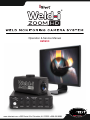
1
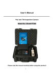
® Operation & Service Manual EM19191 ® www.intertest.com • 303 Route 94 • Columbia, NJ 07832 • 908.496.8008 Table of Contents Introduction 3 Customer Support 4 Warranty Information 5 System Overview 6 Assembly Connection Diagram 7 Spatter Shield Setup 8 Optional Filter Setup 9 Camera Head/Control Unit Setup 9 Operation Manual Camera Settings 11 Menu Settings 13 Changing Menu Settings 15 Care & Maintenance 16 To avoid injury, read and understand documentation prior to operation. Direct any questions about operation to InterTest®at (908) 496-8008 or [email protected] 2 Introduction Congratulations on your investment in our Weld-i® Zoom HD camera system! We are pleased that you selected the Weld-i® Zoom HD from iShot Imaging for your in-process weld monitoring needs. The Weld-i® Zoom HD represents one of the finest high-definition weld monitoring systems in the world for manual and automated weld quality control. Many additional features of the Weld-i® Zoom HD will enhance your “in-process” inspection. Call your InterTest® Sales Representative for more information at 908-496-8008. High Definition with Zooming Capability The Weld-i® Zoom HD camera system uses the state of the art zoom camera that boasts Full HD picture at 1080/60p (1920 x 1080) and has a 10x Zoom capability. Special Spot Filtering and Wide Dynamic Range The Weld-i® Zoom HD camera system uses advanced camera technology along with a special spot filtered lens in order to adapt to the bright white and UV light produced by various weld types and conditions. Intuitive Control Box The intuitive control box allows the user to adjust the Weld-i® Zoom HD camera head during use. Placed at the operator’s fingertips, all controls are safely away from the harmful environments. 3 Customer Support Service and support for all InterTest Inc. and iShot Imaging products is available by calling (908) 496-8008. We also welcome comments, suggestions and technical inquiries by fax at (908) 496-8004 or Email at [email protected]. Page 5 explains InterTest’s one-year limited warranty on parts and materials. Read all warranty information; register your product on-line at www.intertest.com and save this manual for future reference. If your system requires service, please contact Customer Service at [email protected] or (908) 496-8008. In order to return a product for service you must have an RMA (Return Merchandise Authorization) number. To obtain one, please contact the Customer Service Team at the number above. Have the product name and serial numbers ready for the Customer Service Representative. RMA numbers must appear on related paperwork and be clearly marked on the outside of the box of the returned items. 4 Warranty Warranty Statement InterTest®, Inc. guarantees the custom products manufacture®d by InterTest®, Inc. to be free from defects in materials and workmanship for a period of one (1) year, from the date of original purchase. Any and®all other products not manufactured by InterTest, Inc. will carry the OEM’s limited warranty, which will be passed to the purchaser through and supported by InterTest, Inc. InterTest, Inc.’s obligation under this limited warranty shall be confined to the repair or exchange of any part, or parts thereof, that prove defective under normal use and service for which the product was intended and/or designed for. This limited warranty covers conditions that upon our examination, at our facility, shall disclose, to our satisfaction, to be defective. This limited warranty is in lieu of all other warranties, express or implied, including the warranties of merchantability and fitness for use and of all other obligations or liabilities on our part, and we neither assume, nor authorize any other person to assume for us, any other liabilities in connection with the sale of InterTest, Inc. equipment. This warranty shall not apply to any equipment that has been subject to accident, negligence, alteration, abuse, unauthorized repair, improper storage, or other misuse. This limited warranty applies only to the original purchaser and cannot be assigned or transferred to any third party without express written consent from InterTest, Inc. This limited warranty does not apply to consumable items, expendable items or normal wear and tear, nor does it apply to failure due to radiation, overheating and / or below freezing temperatures. Additionally, InterTest®, Inc. assumes no responsibility, either expressed or implied, regarding the improper usage of this equipment or interpretation of test data derived from this product. InterTest, Inc.’s responsibility and obligations, in all cases, are limited strictly to the repair and/or replacement costs outlined above. All sales will be considered final and all orders are non-cancellable, nonreturnable and non-refundable. The laws of the State of New Jersey shall govern this warranty. Note: In the event that the equipment cannot be returned to InterTest, Inc., for whatever reason, the customer agrees to pay for all travel and living expenses incurred to have an InterTest, Inc. Representative evaluate, assess or affect a warranty repair in the field. 5 System Overview LIST OF COMPONENTS FOR STANDARD WELD-I ZOOM HD SYSTEM - EM19191 A1 B C E D F A2 G H FIGURE 1 1 2 A and A B C D E F G H Optional/Not Pictured Component Part# EM10065 EM19107 EM68276 EM19104 EM68278 EM19182 EM16410 EM68282 Description Power Supply Weld-i® Zoom HD Camera Control Unit 25’ D-SUB 9-pin RS-232 Communication Cable Weld-i® Zoom HD Camera Head (includes A2, F, G) 25’ Weld-i® Zoom HD 3G-SDI Video Cable Weld-i® Zoom HD Spatter Shield Kit Weld-i® Zoom HD Magnifying Kit 25’ Weld-i® Zoom HD Power Cable EM19372 25’ Weld-i® Zoom HD LED Illumination Kit EM16414 EM16413 EM16400 EM16402 EM16403 EM16404 EM15915 EM15914 #10 Full Field Weld Glass Filter #8 Full Field Weld Glass Filter 0.5 ND Filter 1.0 ND Filter 1.5 ND Filter Polarizing Filter 0.04 – 2.0 ND Gradient Filter UV Cut Band Pass Filter 6 Assembly 2 CCU CONTROLS LED INTENSITY UP 1 CAMERA HEAD MENU AUTO EXP/ FOCUS IRIS ZOOM Front DOWN LED Brackets* (Optional) EXIT GAIN SHUTTER FOCUS RS-232 LED OUT (optional) 12V/DC IN Back FUSE ON/OFF RS232 4 LED (Optional)* 5 3G-SDI 3 12V Power 12V Power 6 7 8 Power Strip* Monitor* Power Outlet 1 2 3 4 5 EM19104 - Weld-i® Zoom HD Camera Head / 3G-SDI EM19107 - Weld-i® Zoom HD Camera Control Unit EM68278 - 25 foot 3G-SDI Video Cable (Component in Cable Kit EM19183) EM68276 - 25 foot Communication Cable with RS232 Connection (Component in Cable Kit EM19183) EM19372 - (Optional) Illumination Kit - Includes 25 foot LED Power and Intensity Control Cable, 2 Pre-wired LED lights with connector, 2 LED brackets, 4 screws, 25 foot LED Cable, and Allen Key 6 7 8 EM68286 - 25 foot Power Cable, Camera to Power Adapter (Component in Cable Kit EM19183) EM10065 - Power Adapter, Connecting Camera Power Cable to Power Strip EM10065 - Power Adapter, Connecting CCU to Power Strip *Power Strip, Illumination Kit, and Monitor Sold Separately 7 Assembly Spatter Shield Setup: NOTE: Although the Weld-I Zoom HD camera head is generally mounted away from the welding target, it is recommended to use a spatter shield in front of the zoom lens. Follow Spatter Shield Setup steps before completing Camera Head/Control Unit Setup. Figure 2 Figure 3 Figure 4 Figure 5 1. Drop/Place spatter shield in front of camera lens (Figure 2). 2. With fingers, begin threading on the retaining ring (Figure 3). 3. Once started, finish threading on the retaining ring with the retaining ring tool (Figure 4). DO NOT OVERTIGHTEN THE RETAINING RING. This may cause damage to the spatter shield. 4. If further magnification is required, thread on the applicable close up lens by hand (Figure) 8 Assembly Optional Optical Filter Setup: Figure 6 1. Drop/Place applicable optional optical filter in front of camera lens (Figure 6). 2. Follow Spatter Shield Setup steps on page 8. Camera Head/Control Unit Setup: Refer to page 7 connection diagram. 1. Position the Camera Head where needed. Mounting puck is a ¼-20 thread. 2. Position the Camera Control Unit within the distance of cabling. Be sure camera control box Main Power is OFF. 3. Connect Power Adapter to 12V/DC connector on rear of camera control box (Connection 8). 4. Plug Power Adapter into Power Strip* (Connection 8) (*Power Strip not included). 9 Assembly 5. Plug Communication Cable into rear of Camera Head (Connection 4). 6. Plug Communication Cable to RS-232 connector on rear of Camera Control Unit (Connection 4). 7. Plug 3G-SDI Cable into rear of Camera Head (Connection 3). 8. Plug 3G-SDI Cable into Monitor* with 3G-SDI input (Connection 3) (*Monitor not included). 9. Plug Power Cable into rear of Camera Head (Connection 6). 10. Plug Power Cable into Power Adapter (Connection 6 to 7). 11. Plug Power Adapter into Power Strip* (Connection 7) (*Power Strip not included). 12. Power on Monitor and video will appear. 13. Turn ON Power Switch on rear of Camera Control Unit. 14. Wait 10 seconds or until “VERSION 1.1” disappears from the top left of the picture before using Camera Control Unit. 10 OPT Operation Camera Control Unit Operation: BEFORE USING CAMERA CONTROL UNIT: Be sure to follow the Camera Head/Control Unit Setup steps on page 9. The Camera Head must be powered on BEFORE the Camera Control Unit to function. * A B C D E F G H I J Figure 7 SWITCHES FOR MANUAL CAMERA SETTINGS For all switch settings, refer to Figure 7 Auto Exposure/Auto Focus: Press up once on (C) to enter Auto Exposure and Auto Focus mode. Using Gain (H), Iris (D), Shutter (I), or Focus (J) will cause the camera to leave Auto Exposure/Focus mode. Gain Control: To manually adjust Gain, press down once on GAIN (H) rocker switch. Then incrementally press UP (A) or DOWN (F) to adjust gain. UP (A) increases gain, DOWN (F) decreases gain. 11 OPT Operation Iris Control: To manually adjust Iris, press up once on IRIS (D) rocker switch. Then incrementally press UP (A) or DOWN (F) rocker switch to adjust iris. UP (A) opens the iris, DOWN (F) closes the iris. Shutter Speed Control: To manually adjust Shutter Speed, press down once on SHUTTER (I) rocker switch. Then incrementally press UP (A) or DOWN (F) rocker switch to adjust the shutter speed. UP (A) increases shutter speed, DOWN (F) decreases shutter speed. Zoom Control: To adjust the camera zoom, press up once on ZOOM (E) rocker switch. Then continually press UP (A) or DOWN (F) rocker switch to adjust camera zoom. UP (A) zooms in, DOWN (F) zooms out. Focus Control: To manually adjust the picture focus, press down once on FOCUS (J) rocker switch. Then continually press UP (A) or DOWN (F) rocker switch to adjust picture focus. UP (A) focuses far or beyond the subject, DOWN (F) focuses near or in front of the subject. 12 OPT Operation Optional LED Control: IF EM19372 Illumination kit is purchased, LED Intensity is adjusted using the control knob (*) on the front panel of the Control Box labeled ‘LED Intensity’. Twisting the knob to the clockwise will increase intensity while twisting the knob to the counter-clockwise will decrease the intensity. Turn LEFT until the knob clicks to turn lights off. NOTE: All of the previous camera adjustment settings will work independently with each other. If any of the following Menu settings are adjusted, the manual settings will be restored to default. MENU SETTINGS To access the MENU, press up on the MENU (B) rocker switch up (Figure 7). INITIAL MENU SETTINGS (appears in upper left corner of picture) DEFOG OFF WIDE DYNAMIC OFF INFRARED OFF AUTO SLOW SHUT OFF BACKLIGHT OFF STABILIZE N/A PICTURE FLIP OFF MIRROR OFF 13 OPT Operation MENU SETTING DESCRIPTIONS DEFOG – Defog mode is a camera function for when the surrounding area of the subject in the image is foggy and has low contrast. This mode will automatically make the subject appear clearer. WIDE DYNAMIC – Wide Dynamic Range mode is a camera function that divides the image into several blocks and corrects the blockedup shadows and blown-out highlights. This is very useful for viewing welding applications. It makes the high and low light intensities more homogenous in the image. INFRARED – Infrared mode turns the image black and white. AUTO SLOW SHUT – Auto Slow Shutter mode automatically makes the shutter speed slow if the image has low light. BACKLIGHT – Backlight mode is a function that makes the subject appear clearer if the background is too bright. PICTURE FLIP – A picture-altering mode that flips the image over the X-axis. MIRROR – A picture-altering mode that flips the image over the Yaxis. Recommendation: For most welding applications, keep the Wide Dynamic Range ON (listed as “WIDE DYNAMIC” in the Menu settings). This generally will provide the best quality picture. 14 OPT Operation CHANGING MENU SETTINGS Refer to Figure 7 for changing menu settings 1. Use the UP (A) and DOWN (F) rocker switch to cycle the Menu settings. 2. The setting that is highlighted will blink repeatedly. 3. To change setting from OFFON or ONOFF, press up on the MENU (B) rocker switch. 4. Once a change is made, the Menu will exit automatically. 5. To leave the Menu without making changings, press down on the EXIT (G) switch. 6. To initialize the camera settings, power down the Camera Control Unit and Camera Head. Power on Camera Head then Camera Control Unit in that order. NOTES: - The following Menu settings turns off GAIN, IRIS, or SHUTTER settings: Wide Dynamic Range Auto Slow Shutter Backlight The following Menu setting will not work with each other simultaneously. Each will override the current setting from ONOFF: - Wide Dynamic Range Auto Slow Shutter Backlight (Example: If Wide Dynamic Range is ON, and Auto Slow Shutter is turned ON, Wide Dynamic Range will turn OFF) 15 OPT Care & Maintenance General Care: To ensure a long life for your Weld-i® Zoom HD, it is important to keep it clean and free of corrosive materials. Wipe down the camera head and cable regularly, keep all connectors free of debris and dust, use a spatter shield in front of the lens, and always follow the instructions as described in this manual. AC Fuse Replacement: 1) Turn the power to the system ‘Off’ using the rocker switch on the rear panel of the Camera Control Unit. 2) Unplug the cable from main power and from the rear panel. 3) Turn the Fuse Holder counter clockwise until fuse holder is free. 4) Remove the fuse holder and remove the defective fuse. 5) Replace the fuse with a new 1 amp Slow Blow fuse. 6) Turn the Fuse Holder clockwise until tightened. 7) Plug the power cable into power strip and into the Camera Control Unit 8) Power the system ’On’. 16