1
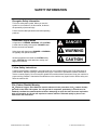
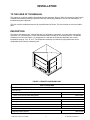
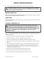
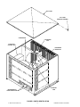
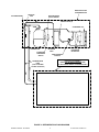
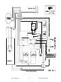
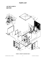
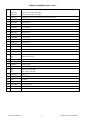
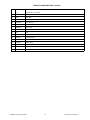
CORNELIUS INC g One Cornelius Place g Anoka, MN 55303-6234
Telephone (800) 238-3600
Facsimile (612) 422-3246
Installation/Service Manual
REMOTE CONDENSING UNIT
UNIT PART NUMBERS:
416117-0001 (R-404A Refrigerant)
496117-0001 (R-404A Refrigerant)
Publication Number: 301138000
Revision Date: May 06, 2014
Revision: B
THIS DOCUMENT CONTAINS IMPORTANT INFORMATION
This Manual must be read and understood before installing or operating this equipment
© 1997-2014 CORNELIUS INC.
PRINTED IN U.S.A
TABLE OF CONTENTS
Page
SAFETY INFORMATION . . . . . . . . . . . . . . . . . . . . . . . . . . . . . . . . . . . . . . . . . . . . . . . . . . . .
1
RECOGNIZE SAFETY INFORMATION . . . . . . . . . . . . . . . . . . . . . . . . . . . . . . .
1
UNDERSTAND SIGNAL WORDS . . . . . . . . . . . . . . . . . . . . . . . . . . . . . . . . . . . .
1
FOLLOW SAFETY INSTRUCTIONS . . . . . . . . . . . . . . . . . . . . . . . . . . . . . . . . .
1
CO2 (CARBON DIOXIDE) WARNING . . . . . . . . . . . . . . . . . . . . . . . . . . . . . . . .
1
INSTALLATION . . . . . . . . . . . . . . . . . . . . . . . . . . . . . . . . . . . . . . . . . . . . . . . . . . . . . . . . . . . .
3
TO THE USER OF THIS MANUAL . . . . . . . . . . . . . . . . . . . . . . . . . . . . . . . . . . . . . . .
3
DESCRIPTION . . . . . . . . . . . . . . . . . . . . . . . . . . . . . . . . . . . . . . . . . . . . . . . . . . . . . . . .
3
UNPACKING AND INSPECTION . . . . . . . . . . . . . . . . . . . . . . . . . . . . . . . . . . . . . . . .
4
INSTALLATION . . . . . . . . . . . . . . . . . . . . . . . . . . . . . . . . . . . . . . . . . . . . . . . . . . . . . . . .
4
SELECTING LOCATION . . . . . . . . . . . . . . . . . . . . . . . . . . . . . . . . . . . . . . . . . . .
4
INSTALLING REMOTE CONDENSING UNIT . . . . . . . . . . . . . . . . . . . . . . . .
5
SERVICE AND MAINTENANCE . . . . . . . . . . . . . . . . . . . . . . . . . . . . . . . . . . . . . . . . . . . . .
7
PERIODIC INSPECTION . . . . . . . . . . . . . . . . . . . . . . . . . . . . . . . . . . . . . . . . . . . . . . .
7
LUBRICATION . . . . . . . . . . . . . . . . . . . . . . . . . . . . . . . . . . . . . . . . . . . . . . . . . . . . . . . .
7
CLEANING CONDENSER COIL . . . . . . . . . . . . . . . . . . . . . . . . . . . . . . . . . . . . . . . . .
7
TROUBLESHOOTING . . . . . . . . . . . . . . . . . . . . . . . . . . . . . . . . . . . . . . . . . . . . . . . . . . . . . .
11
TROUBLESHOOTING REFRIGERATION COMPRESSOR . . . . . . . . . . . . . . . . . .
11
COMPRESSOR COOLS BUT IS VERY NOISY ESPECIALLY WHEN
STOPPING AND STARTING . . . . . . . . . . . . . . . . . . . . . . . . . . . . . . . . . . . . . . . .
11
COMPRESSOR COOLS, BUT IS MODERATELY NOISY; LOUD ENOUGH
TO BE NOTICED, BUT NO SHARP BANGS OR CLATTERING . . . . . . . . .
11
COMPRESSOR OPERATES BUT REFRIGERATION SYSTEM DOES
NOT COOL . . . . . . . . . . . . . . . . . . . . . . . . . . . . . . . . . . . . . . . . . . . . . . . . . . . . . . .
11
COMPRESSOR STARTS AND OPERATES FOR A FEW SECONDS,
THEN STOPS . . . . . . . . . . . . . . . . . . . . . . . . . . . . . . . . . . . . . . . . . . . . . . . . . . . . .
11
COMPRESSOR WILL NOT START . . . . . . . . . . . . . . . . . . . . . . . . . . . . . . . . . .
11
COMPRESSOR STARTS BUT WILL NOT OPERATE FOR MORE THAN
A FEW SECONDS . . . . . . . . . . . . . . . . . . . . . . . . . . . . . . . . . . . . . . . . . . . . . . . . .
12
TROUBLESHOOTING REMOTE CONDENSING UNIT . . . . . . . . . . . . . . . . . . . . .
14
COMPRESSOR DOES NOT OPERATE. . . . . . . . . . . . . . . . . . . . . . . . . . . . . .
14
COMPRESSOR OPERATES CONTINUOUSLY BUT DOES NOT COOL
SUFFICIENTLY . . . . . . . . . . . . . . . . . . . . . . . . . . . . . . . . . . . . . . . . . . . . . . . . . . .
14
CONDENSER FAN MOTOR NOT OPERATING. . . . . . . . . . . . . . . . . . . . . . . .
14
PARTS LIST . . . . . . . . . . . . . . . . . . . . . . . . . . . . . . . . . . . . . . . . . . . . . . . . . . . . . . . . . . . . . .
15
TABLE OF CONTENTS (cont’d)
Page
LIST OF FIGURES
FIGURE 1. REMOTE CONDENSING UNIT . . . . . . . . . . . . . . . . . . . . . . . . . . . . . . .
3
FIGURE 2. PARTS IDENTIFICATION . . . . . . . . . . . . . . . . . . . . . . . . . . . . . . . . . . . .
8
FIGURE 3. REFRIGERATION FLOW DIAGRAM . . . . . . . . . . . . . . . . . . . . . . . . . . .
9
FIGURE 4. WIRING DIAGRAM . . . . . . . . . . . . . . . . . . . . . . . . . . . . . . . . . . . . . . . . . .
10
FIGURE 5. REMOTE CONDENSER ASS’Y . . . . . . . . . . . . . . . . . . . . . . . . . . . . . . .
15
LIST OF TABLES
TABLE 1. DESIGN DATA . . . . . . . . . . . . . . . . . . . . . . . . . . . . . . . . . . . . . . . . . . . . . . .
3
SAFETY INFORMATION
Recognize Safety Information
This is the safety-alert symbol. When you see this
symbol on our machine or in this manual, be alert to
the potentially of personal injury.
Follow recommended precautions and safe operating
practices.
Understand Signal Words
A signal word - DANGER, WARNING, OR CAUTION
is used with the safety-alert symbol. DANGER identifies the most serious hazards.
Safety signs with signal word DANGER or WARNING
are typically near specific hazards.
General precautions are listed on CAUTION safety
signs. CAUTION also calls attention to safety messages in this manual.
DANGER
WARNING
CAUTION
Follow Safety Instructions
Carefully read all safety messages in this manual and on your machine safety signs. Keep safety signs in
good condition. Replace missing or damaged safety signs. Learn how to operate the machine and how to
use the controls properly. Do not let anyone operate the machine without instructions. Keep your machine in
proper working condition. Unauthorized modifications to the machine may impair function and/or safety and
affect the machine life.
CO2 (Carbon Dioxide) Warning
CO2 Displaces Oxygen. Strict Attention must be observed in the prevention of CO2 (carbon dioxide)
gas leaks in the entire CO2 system. If a CO2 gas leak is suspected, particularly in a small area, immediately ventilate the contaminated area before attempting to repair the leak. Personnel exposed to
high concentration of CO2 gas will experience tremors which are followed rapidly by loss of consciousness and suffocation.
Publication Number: 301138000
1
© 1997-2014 Cornelius Inc.
THIS PAGE LEFT BLANK INTENTIONALLY
© 1997-2014 Cornelius Inc.
2
Publication Number: 301138000
INSTALLATION
TO THE USER OF THIS MANUAL
This manual is a guide for installing and maintaining this equipment. Refer to Table of Contents for page location
of detailed information pertaining to questions that may arise during installation, service and maintenance, or
troubleshooting this equipment.
This Unit must be installed and serviced by a qualified Service Person. This Unit contains no user serviceable
parts.
DESCRIPTION
The Remote Condensing Unit consists basically of a refrigeration compressor, a receiver tank, a fan cooled
condenser coil, a head pressure control, and a strainer/dryer mounted on an enclosed platform. The Remote
Condensing Coil Unit (see Figure 1) is designed to be used with any Evaporator Assembly with a rated
temperature range of -10_F to -32_F. The Evaporator Assembly is connected by refrigeration lines and is
refrigerated by the Remote Condensing Unit.
FIGURE 1. REMOTE CONDENSING UNIT
Table 1. Design Data
REMOTE CONDENSING UNIT
Unit Part No.
230V, 60 HZ Unit (R-404A Refrigerant)
4161170001
230V, 50 HZ Unit (R-404A Refrigerant)
4961170001
Overall Dimensions:
Height
22-1/4 inches
Width
28-1/2 inches
Depth
25-3/4 inches
Shipping Weight (approx)
Publication Number: 301138000
290 Pounds
3
© 1997-2014 Cornelius Inc.
Table 1. Design Data (cont’d)
Ambient Operating Temperature
–20_F to 120_F
Refrigeration Requirements:
Refrigeration Type and Charge
See Unit Nameplate
Electrical Requirements:
Operating Voltage
See Unit Nameplate
Current Draw
See Unit Nameplate
UNPACKING AND INSPECTION
NOTE: The Remote Condensing Unit was thoroughly inspected before leaving the factory and the
carri-er has accepted and signed for it. Any damage or irregularities should be noted at time of
delivery (ornot later than 15 days from date of delivery) and immediately reported to the delivering
carrier. Requesta written inspection report from Claims Inspector to substantiate any necessary claim.
File claim withthe delivering carrier, not with Cornelius Inc.
1. Unpack Remote Condensing Unit. Remove all shipping tape and packing materials.
2. Inspect and make sure Remote Condensing Unit is in good condition as instructed in preceding NOTE.
INSTALLATION
SELECTING LOCATION
Locate the Remote Condensing Unit so the following requirements are satisfied:
1. The Remote Condensing Unit must be installed in a location which will allow shortest possible refrigeration
lines route (not to exceed 50–feet in length) from Condensing Unit to the Evaporator Assembly. The Condensing Unit must not be installed more than 10–feet below the Evaporator Assembly Dispenser.
DANGER: To avoid possible fatal electrical shock or serious injury to the operator, it is
highly recommended that a GFI (ground fault circuit interrupt) be installed in the electrical
circuit for the 60 Hz Units. It is required that an ELCB (earth leakage circuit breaker) be
installed in the electrical circuit for the 50 Hz Units.
2. Close to a properly grounded 208/230 VAC 60HZ or 220/240 VAC 50HZ single-phase electrical circuit with
a 30-amp minimum-rated disconnect switch (not provided) fused at 25-amps (‘‘slow-blow’’) or power circuit
connected through an equivalent HACR circuit breaker must be available to the Unit. Use No. 8 AWG copper wire, or larger, depending upon line length, in suitable conduit or BX sheath. POWER CIRCUIT MUST
BE MADE UP OF COPPER CONDUCTORS AND ALL WIRING MUST CONFORM TO NATIONAL AND
LOCAL CODES. MAKE SURE UNIT IS PROPERLY GROUNDED.
3. An extreme warm climate installation may require extra caution in Remote Condensing Unit location. Avoid
hot sunny locations and seek shaded area if possible. If Remote Condensing Unit is to be installed on the
rooftop, the use of a structure to shade the Unit from direct sun exposure and/or a platform extending Unit
an additional 18–inches above the roof is highly recommended and will improve performance. Ample space
(24 inches on all sides and 48 inches above Unit) must be provided for proper air circulation through the
Unit and also access for service and maintenance. DO NOT BLOCK AIR CIRCULATION THROUGH THE
UNIT.
© 1997-2014 Cornelius Inc.
4
Publication Number: 301138000
4. If the Remote Condensing Unit is installed on the rooftop, the Unit must be installed in a level position and
must be anchored with adequate fastening devices.
INSTALLING REMOTE CONDENSING UNIT
(see Figures 2, 3, and 4)
1. Install Remote Condensing Unit meeting requirements of SELECTING LOCATION. The Unit must be
installed in a level position and must be anchored with adequate fastening devices.
NOTE: The following Refrigeration Lines Kits are recommended to connect the Remote
CondensingUnit to the Evaporator Assembly. Contact Cornelius if refrigeration lines exceed 50 feet
in length.
Part No.
Description
308900025
Refrigeration Lines Kit, 25-ft. long 90_ (insulated 3/8 O.D. Liquid and 5/8 O.D. Discharge)
308900050
Refrigeration Lines Kit, 50-ft. long 90_ (insulated 3/8 O.D. Liquid and 5/8 O.D. Discharge)
2. Route refrigeration lines from Remote Condensing Unit to the Evaporator Assembly.
3. Connect ends of refrigeration lines to Remote Condensing Unit refrigeration connectors.
4. Remove four screws securing Remote Condensing Unit top cover, then remove cover for access to electrical control box.
5. Remove one screw securing electrical control box cover, then remove cover.
WARNING: The Remote Condensing Unit must be electrically grounded to avoided
possible fatal electrical shock or serious injury to the operator. A green ground wire is
provided inside electrical control box to connect power circuit ground wire which
electrically grounds the Unit.
6. Connect 208/230 VAC 60HZ or 220/240 VAC 50 HZ Single-Phase electrical power circuit (meeting requirements of SELECTING LOCATION) to L1 and L2 (N) terminals on contactor inside the Unit electrical control
box as shown in FIGURE NO TAG. MAKE SURE POWER CIRCUIT GREEN GROUND WIRE IS
INSTALLED UNDER GREEN GROUND SCREW INSIDE ELECTRICAL CONTROL BOX TO PROPERLY
GROUND THE UNIT. POWER CIRCUIT MUST BE MADE UP OF COPPER CONDUCTORS AND ALL
WIRING MUST CONFORM TO NATIONAL AND LOCAL ELECTRICAL CODES.
7. A 24 VAC power circuit, which must conform to national and local electrical codes, must be routed and
connected between the Evaporator Assembly Temperature Control and the Remote Condensing Unit. Purpose of the 24VAC power control circuit is to allow the Evaporator Assembly Temperature Control to control ‘‘ON’’ and ‘‘OFF’’ operation of the Remote Condensing Unit. Route and connect 24VAC power control
circuit between the Evaporator Assembly and the Remote Condensing Unit as follows:
A.
Route 24 VAC power control circuit electrical wires through hole in end panel to inside of the Remote
Condensing Unit.
B.
Connect 24 VAC power control circuit electrical wires to labeled 24 V grey and red wires hanging out
of the electrical control box.
C.
Install electrical control box cover and secure with screw.
D.
Route 24VAC power control circuit from Remote Condensing Unit to the Evaporator Assembly location.
E.
Refer to manual provided with the Evaporator Assembly for instructions to connect 24VAC power circuit to Evaporator Assembly Temperature Control.
Publication Number: 301138000
5
© 1997-2014 Cornelius Inc.
THIS PAGE LEFT BLANK INTENTIONALLY
© 1997-2014 Cornelius Inc.
6
Publication Number: 301138000
SERVICE AND MAINTENANCE
This section describes service and maintenance procedures to be performed on the Unit.
WARNING: Disconnect electrical power to Remote Condensing Unit to prevent personal
injury before attempting any internal maintenance. Only qualified personnel should service
internal components or electrical wiring.
PERIODIC INSPECTION
Make sure Remote Condensing Unit Condenser Coil is free from debris. Restricting air through the condenser
coil will decrease the refrigeration systems cooling efficiency.
LUBRICATION
The Remote Condensing Unit condenser fan motor must be lubricated once every six months with S.A.E. 20W
oil. DO NOT OVER OIL.
CLEANING CONDENSER COIL
CAUTION: Remote Condensing Unit is equipped with a condenser coil that must be
cleaned every 30 days. Allowing condenser coil to become clogged will cause refrigeration
system to overheat which will automatically shut refrigeration system down. After
condenser coil has been cleaned, high–pressure cutout sensing switch (located inside the Remote
Condensing Unit electrical control box) will automatically reset to restart the refrigeration system.
OPERATING IN THIS MANNER FOR PROLONGED PERIODS OF TIME COULD RESULT IN
COMPRESSOR FAILURE.
The Remote Condensing Unit condenser coil must be cleaned every 30 days. Circulating air, required to cool
the coil, is drawn in through the coil and is exhausted out through grilles on end and back of the Unit. Clean
condenser coil as follows:
1. Disconnect electrical power from Evaporator Assembly 24VAC Temperature Control.
2. Disconnect electrical power to Remote Condensing Unit at disconnect switch.
3. Remove four screws securing top cover on Remote Condensing Unit, then remove cover.
4. Clean condenser coil using vacuum cleaner, whisk broom, or a soft–bristle brush to remove any debris
from coil.
5. Make sure fan blade is not out of balance, is not bent, and is not striking any surface during rotation.
6. If the Remote Condensing Unit has been installed on the rooftop check and make sure roof area
immediately surrounding the Remote Condensing Unit is free and clear of any debris that may have
collected such as leaves, paper, trash, etc.
7. Install top cover on Remote Condensing Unit and secure with four screws.
8. Restore electrical power to Remote Condensing Unit at disconnect switch.
9. Restore electrical power to Evaporator Assembly 24VAC Temperature Control.
Publication Number: 301138000
7
© 1997-2014 Cornelius Inc.
TOP COVER
TOP COVER
RETAINING SCREW(4)
COMPRESSOR
CONDENSER
COIL
ELECTRICAL
CONTROL BOX
CONDENSER
FAN MOTOR
RECEIVER
TANK
REFRIGERATION
LINES CONNECTORS
FIGURE 2. PARTS IDENTIFICATION
© 1997-2014 Cornelius Inc.
8
Publication Number: 301138000
REMOTE ROOFTOP
CONDENSING UNIT
STRAINER/DRYER
PROCESS
LINE
HIGH-PRESSURE
CUTOUT SWITCH
SERVICE VALVE (2)
CONDENSER COIL
COMPRESSOR
RECEIVER
TANK
CONDENSER
FAN/HEATER
SWITCH
CONDENSER
MOTOR/FAN
HEAD PRESSURE
CONTROL
EVAPORATOR ASSEMBLY
(MUST NOT BE INSTALLED MORE THAN
10–FEET ABOVE REMOTE CONDENSING UNIT)
REFRIGERATION
LINES
(NOT TO EXCEED
50–FEET IN LENGTH)
FIGURE 3. REFRIGERATION FLOW DIAGRAM
Publication Number: 301138000
9
© 1997-2014 Cornelius Inc.
FIGURE 4. WIRING DIAGRAM
© 1997-2014 Cornelius Inc.
10
Publication Number: 301138000
TROUBLESHOOTING
IMPORTANT: Only qualified personnel should service internal components or electrical wiring.
WARNING: If repairs will be made to Remote Condensing Unit, turn off electrical power to
Evaporator Assembly, then disconnect power to Remote Condensing Unit at disconnect
switch before proceeding.
Trouble
Probable Cause
Remedy
TROUBLESHOOTING REFRIGERATION COMPRESSOR
COMPRESSOR COOLS BUT
IS VERY NOISY ESPECIALLY
WHEN STOPPING AND
STARTING
A.
Compressor cools, but is very
noisy, especially when
stopping and starting. This is
either a broken suspension
spring or loose crank shaft
extension.
A.
Compressor must be changed.
COMPRESSOR COOLS, BUT
IS MODERATELY NOISY;
LOUD ENOUGH TO BE
NOTICED, BUT NO SHARP
BANGS OR CLATTERING
A.
Compressor cools but is
moderately noisy, loud enough
to be somewhat annoying, but
no sharp bangs or clattering.
A.
This is probably a discharge or
suction tube rattling inside the
compressor. If noise level can be
tolerated, compressor need not
be changed. The noise will not
affect the performance or shorten
compressor life.
COMPRESSOR OPERATES
BUT REFRIGERATION
SYSTEM DOES NOT COOL
A.
Look for a refrigerant leak or
oil at tubing joints. If
compressor is moderately
noisy and no leaks are
evident, it is probably a broken
valve inside compressor
A.
Compressor must be changed.
COMPRESSOR STARTS AND
OPERATES FOR A FEW
SECONDS, THEN STOPS
A.
Compressor running too hot
due to condenser coils
plugged with dust, lint, and
grease restricting cooling air
flow through the condenser
coil.
A.
Clean condenser coil with vacuum
cleaner, low-pressure
compressed air, or soft brush,
then allow compressor to cool and
restart.
COMPRESSOR WILL NOT
START
A.
Check line voltage across ‘‘T‘’
terminals on contactor.
A.
Voltage cannot be less than 198 V
to start compressor.
B.
loose or disconnected wires.
B.
Correct the loose or
disconnected wires.
C.
Check control circuit;
C.
Contactor must pull in.
D.
Examine start capacitor for
signs of excessive heat (blown
up). Check for open by
connecting test cord and
checking amp draw.
D.
If no current is drawn (or very
little), capacitor is open and must
be replaced.
If capacitor is blown, look for
inoperable start relay or low
voltage..
Note: If all above checks have been made and compressor will not start, increase start capacitor value
by about 15% and try to start. This can be done two ways: (The substitute capacitor must have voltage
rating equal to or greater than the existing start capacitor) a. Remove existing capacitor and replace
with one having a 15% greater MFD rating or (step b). b. Wire capacitor that has 15% of the MFD rating
in parallel with the existing capacitor. c. Try to start compressor. If all the previous (steps a and b) will
not make compressor operate, label compressor ‘‘stuck’’ and replace.
Publication Number: 301138000
11
© 1997-2014 Cornelius Inc.
Trouble
COMPRESSOR STARTS BUT
WILL NOT OPERATE FOR
MORE THAN A FEW
SECONDS
Probable Cause
A.
Inoperable Start Relay.
Remedy
A.
Replace start relay.
B.
If less than 198 V is present,
upgrade Unit power source.
Note: To check relay, remove
wire from No. 1 terminal on start
relay and touch to No. 2 terminal. Start compressor and immediately remove wire from No.
2 terminal. If compressor starts
and operates, problem is in the
start relay.
B.
Low Voltage.
Note: Remove compressor terminals cover and connect voltmeter test leads between ‘‘C’’ (top
terminal) and ‘‘R’’ (lower right
terminal). Start compressor. A
minimum of 198 VAC (nominal)
must be present to operate compressor
WARNING: To avoid electrical shock even after electrical power has been disconnected from
Unit, run capacitor must be discharged by momentarily touching both capacitor terminals at
the same time using an insulated handled screwdriver.
C.
© 1997-2014 Cornelius Inc.
Inoperative Run Capacitor.
12
C.
Inspect capacitor for bulges,
cracks, or any external
deformation. If found, assume
capacitor is inoperable and
replace. If none of the above
conditions are evident, disconnect
wires from capacitor. Connect test
cord to capacitor terminals.
Connect ammeter to one wire of
test cord, Plug test cord into
electrical outlet and record amp
reading. *See formula on next
page at end of this trouble topic.
Publication Number: 301138000
Trouble
COMPRESSOR STARTS BUT
WILL NOT OPERATE FOR
MORE THAN A FEW
SECONDS (CONT’D)
Probable Cause
D.
Grounded or Shorted Motor
Windings.
Remedy
D.
Disconnect all electrical wires
from compressor terminals. Set
ohmmeter on 100,000 ohm scale.
touch one lead to copper line or
bare metal of compressor. Touch
other lead to each of the
compressor terminals in
succession. Continuity must not
be indicated. If an ohmmeter
reading is obtained, then
compressor is grounded and must
be replaced. To check for shorted
windings, set ohmmeter on 10
ohm scale. Attach one lead to ‘‘C’’
(top terminal). The reading should
be approximately 1 to 1-1/2 ohms.
Leave one lead on ‘‘C‘’ terminal
and touch other lead to ‘‘S‘’ (lower
left terminal).The reading should
be 3-1/2 to 5 Ohms. Leave one
lead on ‘‘S’’ terminal and touch
other lead to ‘‘R’’ terminal. This
reading should be exactly the sum
of the first two readings obtained.
If the resistance readings do not
fall within these limits, the
compressor is ‘‘shorted’’ or has an
‘‘open’’ winding and must be
replaced. Replace compressor.
2650xAmp
*Use amps reading in formula voltsń60HZ = M.F.D. to determine actual value of capacitor. If calculated actual value is 10% more or less than rated value, replace capacitor.
Publication Number: 301138000
13
© 1997-2014 Cornelius Inc.
Trouble
Probable Cause
Remedy
TROUBLESHOOTING REMOTE CONDENSING UNIT
COMPRESSOR DOES NOT
OPERATE.
COMPRESSOR OPERATES
CONTINUOUSLY BUT DOES
NOT COOL SUFFICIENTLY
CONDENSER FAN MOTOR
NOT OPERATING.
© 1997-2014 Cornelius Inc.
A.
Evaporator Assembly not
calling for refrigeration.
A.
Refrigeration not called for.
B.
Electrical power to Remote
Condensing Unit turned off.
B.
Turn on electrical power to
Remote Condensing Unit.
C.
Electrical power to Evaporator
Assembly turned off.
C.
Turn on electrical power to
Evaporator Assembly.
D.
No Remote Condensing Unit
power source. Blown fuse or
tripped circuit breaker.
D.
Replace fuse or reset circuit
breaker.
E.
Loose, disconnected, or
broken wiring.
E.
Tighten connections or replace
broken wiring
F.
High–pressure cutout switch
tripped.
F.
High-pressure cutout switch will
automatically reset after
refrigeration system pressure has
lowered (see CAUTION note
under CLEANING CONDENSER
COIL).
G.
Low voltage.
G.
Voltage must be at least 198 V at
compressor terminals when
compressor is trying to start.
H.
Inoperable run capacitor, or
start relay.
H.
Replace inoperable part.
I.
Inoperable compressor.
I.
Replace compressor.
A.
Refrigeration capacity is
exceeded by product
overdrawing.
A.
Reduce amount of product drawn
per given time.
B.
Air circulation through Remote
Condensing Unit condenser
coil is restricted.
B.
Check and if necessary, clean
condenser coil as instructed.
C.
Insufficient refrigerant charge.
C.
Find and repair refrigeration leak,
then replenish refrigerant charge.
A.
Fan blade obstructed
A.
Remove obstruction.
B.
Inoperative condenser fan
motor.
B.
Replace condenser fan motor.
C.
Compressor contactor
inoperable.
C.
Replace compressor contactor.
D.
Disconnected or broken
electrical wire.
D.
Connect or repair broken
electrical wire.
14
Publication Number: 301138000
PARTS LIST
UNIT PART NUMBERS:
416117-0001
496117-0001
40.
24.
33.
1.
36.
35.
34.
31.
2.
32.
42.
1.
25.
1.
30.
6.
28.
16.
27.
1.
26.
41. 29.
11.
12.
13.
14.
15.
18.
19.
1.
1. 21.
23.
9.
17.
41.
43.
1.
1.
20.
1.
8.
7.
44.
10.
5.
1.
9.
37.
22.
3.
4.
1.
1.
FIGURE 5. REMOTE CONDENSER ASS’Y
Publication Number: 301138000
15
© 1997-2014 Cornelius Inc.
1.
REMOTE CONDENSER ASS’Y (CON’T)
Item
Part No.
Description
4161170001
Remote Condenser Ass’y, 230V 60HZ
4961170001
Remote Condenser Ass’y, 230V 50HZ
1.
*319941000
Thread Rolling Screw, SL Hex Washer HD. No. 8-32 By 3/8 in. Long
2.
324153068
Cover, Remote Condenser
3.
324151068
Panel, Right-Side
4.
324152068
Panel, Back
5.
324150068
Panel, Left-Side
6.
324148000
Condenser Coil
7.
309215000
Pressure Control
8.
3557
Dryer
9.
*189429000
Hex Nut, 1/4-20
10.
5041
Receiver
11.
*186146000
Hex Nut, 5/16-18
12.
*186148000
Washer, Lock, .319 I.D.
13.
318418000
Washer .312 I.D.
14.
3609
Spacer
15.
3608
Grommet
16.
3726
Compressor, 230V 60HZ
3725
Compressor, 230V 50HZ
17.
309919000
Flange, 3/8
18.
309920000
Flange, 1/2
19.
309895011
Bracket, Coupler
20.
324155000
Bracket, Motor
21.
2893
Motor, 1/6 H.P., 230V. 60HZ
2115
Motor, 1/6 H.P., 230V. 50HZ
22.
324145000
Blade, Fan
23.
324154000
Shroud
24.
4999
Control Box
25.
324156000
Cover, Control Box
26.
324172000
Strap, Capacitor Fan
27.
324143000
Capacitor, Start, Fan
28.
325956000
Strap, Capacitor
© 1997-2014 Cornelius Inc.
16
Publication Number: 301138000
REMOTE CONDENSER ASS’Y (CON’T)
29.
325518000
Capacitor, Run, 230V 60HZ
3617
Capacitor, Run, 230V 50HZ
30.
40284000
Capacitor, Start
31.
40285
Relay, Start
32.
324209000
Pressure Switch, HI, 200 PSI
33.
329473000
Contactor, 24V.
34.
*325069000
Machine Screw, S: Hex HD, No. 10-24 by 1/2-in. Long
35.
325145000
Washer, #10
36.
325644000
Lug
37.
5042
Base
38.
*187552000
Machine Screw, Phil RD HD, No. 8-32 by 1/4-in. Long (Not Shown)
39.
309524011
Cord (Not Shown)
40.
320734000
Self-Threaded Screw, Phil Pan HD. No. 6-32 by 3/8-in. Long
41.
313802000
Snap Bushing
42.
324208000
Pressure Switch, HI, 405 PSIG
43.
960194000
Edging, Grommet
44.
324215000
Heater, 138 Watt, 220V. 60Hz
Publication Number: 301138000
17
© 1997-2014 Cornelius Inc.
THIS PAGE LEFT BLANK INTENTIONALLY
© 1997-2014 Cornelius Inc.
18
Publication Number: 301138000
CORNELIUS INC.
CORPORATE HEADQUARTERS:
One Cornelius Place
Anoka, Minnesota 55303-6234
(612) 421-6120
(800) 238-3600
![Service Manual VA13 Carbonator [ 002818 ]](http://vs1.manualzilla.com/store/data/006013608_1-0f8f87056a0ab013b1dd01dac3912d47-150x150.png)