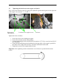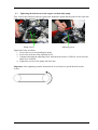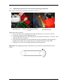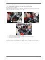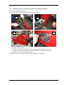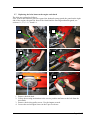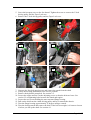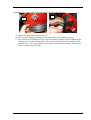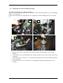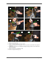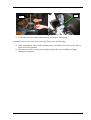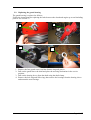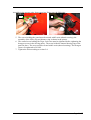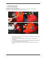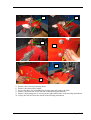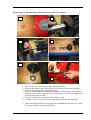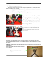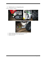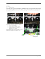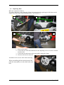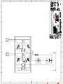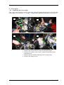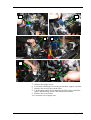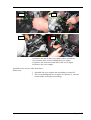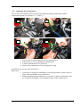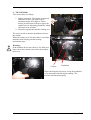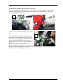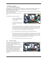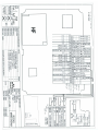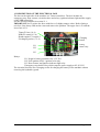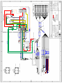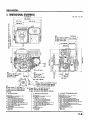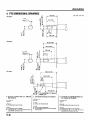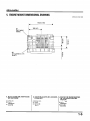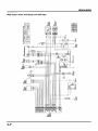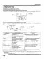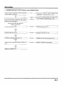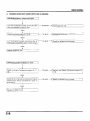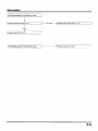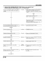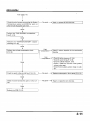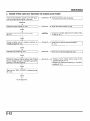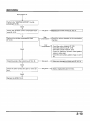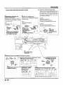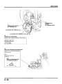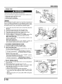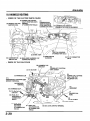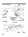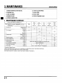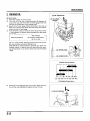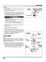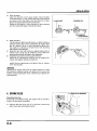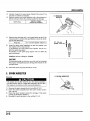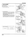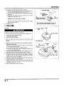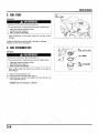
1
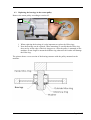
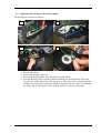
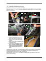
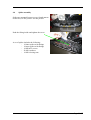
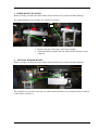
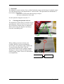
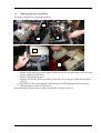
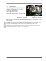
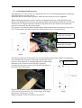
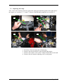
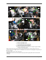
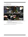
Service manual
RC-750
Valid for RC-750 type and serial number:
410100-01
Page 1 / 57
1
REMOVING GUARDS ........................................................................................................ 4
1.1
1.2
1.3
1.4
1.5
1.6
2
PROPULSION SYSTEM...................................................................................................... 7
2.1
2.2
2.3
2.4
2.5
2.6
2.7
2.8
2.9
3
TIGHTENING AND MAINTENANCE OF DRIVING BELTS ...................................................... 7
TIGHTENING THE BELTS BETWEEN THE ENGINE AND CLUTCH ......................................... 8
TIGHTENING THE BELTS BETWEEN THE ENGINE AND HYDRAULIC PUMP .......................... 9
TIGHTENING THE BELTS BETWEEN THE CLUTCH AND MOWING MECHANISM ................. 10
REPLACING THE BELT BETWEEN THE ENGINE AND HYDRAULIC PUMP ........................... 11
REPLACING THE BELTS BETWEEN THE CLUTCH AND MOWING MECHANISM ................... 12
REPLACING THE BELTS BETWEEN THE ENGINE AND CLUTCH ......................................... 13
REPLACING THE CLUTCH AND FLANGE BEARINGS ......................................................... 16
REPLACING THE GUARD BEARING ................................................................................. 19
MOWING MECHANISM .................................................................................................. 21
3.1
3.2
3.3
3.4
4
REMOVING THE BRANCHES PROTECTIVE GUARD ............................................................. 4
REMOVING THE HYDRAULICS GUARD ............................................................................. 4
REMOVING THE GUARD ON THE RIGHT SIDE OF THE ENGINE............................................ 5
REMOVING THE BLACK GUARD IN FRONT OF THE CLUTCH .............................................. 5
REMOVING THE ENGINE COMPARTMENT GUARD ............................................................. 6
REMOVING THE MOWING MECHANISM GUARD ................................................................ 6
REMOVING THE FLAIL AXIS ........................................................................................... 21
REPLACING THE BEARINGS IN THE FLAIL AXIS .............................................................. 23
FLAIL CUTTERS, HANGERS AND SCREWS ....................................................................... 25
REPLACING THE CASES OF SUPPORTING ARMS .............................................................. 26
BELTS ................................................................................................................................. 27
4.1
4.2
4.3
4.4
4.5
4.6
BELTS TENSION............................................................................................................. 27
REPLACING BELTS ........................................................................................................ 28
REPLACING THE BEARINGS IN THE RETURN PULLEY ...................................................... 29
REPLACING THE BEARINGS IN THE BEARING PULLEY .................................................... 30
REPLACING THE HYDRAULIC WHEELS MOTOR............................................................... 31
SPIKES ASSEMBLY ........................................................................................................ 32
5
RUBBER BELT HANGERS .............................................................................................. 33
6
AIR TRAP RUBBER BUMPS ........................................................................................... 33
7
HYDRAULICS ................................................................................................................... 34
7.1
7.2
7.3
7.4
7.5
7.6
7.7
8
CHECKING THE HYDRAULIC OIL LEVEL ......................................................................... 34
REPLACING THE GEAR OIL AND FILTER ......................................................................... 35
MACHINE TOWING ........................................................................................................ 36
CHECKING HYDRAULIC PRESSURE ................................................................................ 37
REPLACING THE PUMP .................................................................................................. 38
CLEANING THE OIL-COOLER ......................................................................................... 40
HYDRAULICS DIAGRAM ................................................................................................ 41
SERVO-ENGINE................................................................................................................ 42
8.1
8.2
8.3
REPLACING THE SERVO-ENGINE ................................................................................... 42
REPLACING THE POTENTIOMETER ................................................................................ 45
SETTING THE ZERO POSITION OF THE SERVO-ENGINE .................................................... 46
Page 2 / 57
9
TILT SENSOR .................................................................................................................... 47
10
MOWING MECHANISM SAFETY SENSOR .............................................................. 48
11
REMOTE CONTROL..................................................................................................... 49
11.1
11.2
12
ZERO POSITION PROGRAMMING .................................................................................... 49
FREQUENCY CHANGE .................................................................................................... 49
DESCRIPTION OF THE ELECTRICAL BOX ............................................................. 50
12.1
ELECTRICAL DIAGRAM ................................................................................................. 51
13
TROUBLESHOOTING .................................................................................................. 52
14
HONDA IGX 440............................................................................................................ 54
14.1
14.2
14.3
14.4
14.5
MODIFICATION OF HONDA IGX440 ENGINE ................................................................. 54
DIAGNOSTIC CONNECTION ............................................................................................ 55
REPLACING THE MOTOR OIL.......................................................................................... 55
FUEL SYSTEM TROUBLESHOOTING ................................................................................ 56
HONDA ENGINE SERVICE MANUAL ............................................................................... 57
Page 3 / 57
1
REMOVING GUARDS
1.1 Removing the branches protective guard
The protective guard is removed as follows:
1
D
1. Loosen the screws holding the
protective guard in the front part of the
machine.
2. Tilt the protective guard backwards.
3. Tilt the protective guard around the
centre of rotation on the rear part of the
machine and lay it on the floor.
1.2
3
Removing the hydraulics guard
1
2
1. Loosen the six screws holding the guard.
2. Lift the guard directly up and remove it from the machine.
Page 4 / 57
1.3
Removing the guard on the right side of the engine
First, remove the branches protective guard and the hydraulics guard, see sections 1.1, 1.2.
1
2
1. Loosen the rear screw.
2. Press the belt with the left hand and lift off the guard sideways.
1.4
Removing the black guard in front of the clutch
First, remove the branches protective guard, the hydraulics guard and the guard on the right side
of the engine. See sections 1.1-1.3.
1
1. Loosen the three screws and then lift up the guard.
Page 5 / 57
1.5
Removing the engine compartment guard
First, remove the branches protective guard and also the hydraulics guard. See sections 1.1, 1.2.
1
2
3
1. The guard on the right side.
2. Loosen the two screws between the
belts.
3. Then lift up the guard.
1.6
Removing the mowing mechanism guard
1
2
1. Loosen the six screws holding the guard, three on the upper side and three on
the lower side.
2. Then remove the guard.
Page 6 / 57
2 Propulsion system
2.1
Tightening and maintenance of driving belts
To ensure that the belts are set and maintained correctly a belt tightening tester is supplied with
the machine. Driving with belts that are too loose will considerably reduce the lifetime and
efficiency of the belts and the driving pulleys will wear very quickly. If the belts are too tight, it
will increase wear and tear on the machine bearings.
The belt tightening tester is used as follows:
1. Before you start measuring, turn the transmission several times to spread the tension
across the entire belt.
2. Place the belt tightening tester between the
driving pulleys and push the pointer to the
scale.
3. Only use one finger to control the belt
tightening tester.
4. Activate the tester slowly by increasing the
pressure until you hear/feel a click after
which do not exert pressure.
5. Remove the tester from the belt and read
the tension in the intersection of the scale
and the front part of the pointer.
6. Continue setting the belt tension until the value measured and the value in the table
below are equal. After each
adjustment, turn the
transmission several times to
make sure that the belt tension
near the driving pulley is the
same as in the rest of the belt.
Static belt tension (N)
Belts between the engine and clutch
Belts between the engine and pump
Belts between the clutch and mowing
mechanism
New belt Used belt
375
300
250
225
375
300
Important: After tightening turn the transmission several times to spread the tension of the belt
evenly.
Page 7 / 57
2.2
Tightening the belts between the engine and clutch
First, remove the branches protective guard, the hydraulics guard and the guard on the right side
of the engine. See sections 1.1, 1.2 and 1.3.
Belt tension
adjusting nut
Location of the engine screws
Lock-nut
Tighten the belts as follows:
1. Loosen the four screws holding the engine.
2. Loosen the lock-nuts on the setting fitting.
3. Continue adjusting the lock-nuts until the belt tension is 375 N for a new belt and 300 N
for a used belt.
4. Using the horizontal batten check whether the driving pulley of the engine is parallel to
the clutch. If not, adjust the lock-nuts. Check the belt tension afterwards.
5. Tighten the screws of the engine and lock-nuts.
Important: After tightening turn the transmission several times to spread the belt tension
evenly.
Page 8 / 57
2.3
Tightening the belts between the engine and hydraulic pump
First, remove the branches protective guard, the hydraulics guard and the guard on the right side
of the engine. See sections 1.1, 1.2 and 1.3.
Pump screws
Adjusting screw
Tighten the belts as follows:
1. Loosen the two screws holding the pump.
2. Loosen the lock-nut of the adjusting screw.
3. Continue adjusting the adjusting screw until the belt tension is 250N for a new belt and
200N for a used belt.
4. Tighten the screws of the pump and lock-nuts.
Important: After tightening turn the transmission several times to spread the belt tension
evenly.
Page 9 / 57
2.4
Tightening the belts between the clutch and mowing mechanism
First, remove the mowing mechanism guard. See section 1.6.
Adjusting screw
Lock-nut Mowing mechanism
screws
Horizontal batten
Tighten the belts as follows:
1. Loosen the four screws holding the mowing mechanism, two screws on each side.
2. Loosen the lock-nuts on the adjusting screws.
3. Continue adjusting the nut on the adjusting screw until the belt tension is 375N for a new
belt and 300N for a used belt.
4. Using the horizontal batten, check whether the mowing mechanism driving pulley is
parallel to the clutch. If not, adjust the nuts. Check the belt tension afterwards.
5. Tighten the screws of the mowing mechanism and also the nuts.
Important: After tightening turn the transmission several times to spread the belt tension
evenly.
Page 10 / 57
2.5
Replacing the belt between the engine and hydraulic pump
The belt is replaced as follows:
First, remove the branches protective guard, the hydraulic pump guard and the guard on the
right side of the engine. See sections 1.1, 1.2 and 1.3.
2.
1.
2.
1. Loosen the two screws holding the pump.
2. Loosen the adjusting screw nut and tilt the pump towards the engine.
3. Now the belt can be removed.
Assemble in the reverse order from removing. See section 2.3 for the correct belt tension.
Page 11 / 57
2.6
Replacing the belts between the clutch and mowing mechanism
The belts are replaced as follows:
First, remove the mowing mechanism guard. See section 1.6.
1.
2.
3.
4.
1. Remove the belt shaft.
2. Lift up the mowing mechanism to the service position and remove the belt.
3. Lift up the machine so that the mowing mechanism is in the lowest position.
4. Remove the mowing mechanism belts.
Assemble in the reverse order from removing. Tighten as in section 2.4.
Page 12 / 57
2.7
Replacing the belts between the engine and clutch
The belts are replaced as follows:
First, remove the branches protective guard, the hydraulic pump guard, the guard on the right
side of the engine, the guard in front of the clutch and the mowing mechanism guard, see
sections 1.1, 1.2, 1.3, 1.4 and 1.6.
2.
1.
3.
5.
4.
6.
1. Remove the belt shaft.
2. Lift up the mowing mechanism to the service position and remove the belt from the
driveshaft.
3. Remove the driving pulley screw. Use the impact wrench.
4. Loosen the two hexagon screws in the Taper Lock case.
Page 13 / 57
5. Screw the hexagon screw to the free thread. Tighten the screw to remove the V-belt
driving pulley and the Taper Lock case.
6. Remove the V-belt driving pulley and the Taper Lock case.
8.
7.
11.
13.
12.
14.
7. Unscrew the four belt guard screws and remove the guard from the shaft.
8. Lift up the mowing mechanism to the service position.
9. Remove the hydraulic pump belt. See section 2.5.
10. Loosen the engine and set it to the adjusting screws so that the belts are loose. See
section 2.2 on tightening belts between the clutch and engine.
11. Loosen the two screws holding the most rearward flange bearing.
12. Pull out the belt from the clutch driving pulley and lay it towards the chassis.
13. Turn the flange bearing approximately 25 degrees using a wrench.
14. Turn the shaft upwards and remove the belts. If the belt is too tight, it is better to loosen
it before you lift up the shaft. See section 4.1.
Page 14 / 57
Assemble in the reverse order from removing. Please note the following:
17.
16.
15. Tighten the belt as shown in section 2.2.
16. The screws holding the guard must be treated with Loctite (thread securing).
17. The central screw holding the Taper Lock case must be tightened before tightening the
hexagon screws in the driving pulley. The screw holds the internal bearing ring of the
guard in place. The screw must be treated with Loctite (thread securing). The hexagon
screws are tightened to 20 NM.
Page 15 / 57
2.8
Replacing the clutch and flange bearings
The clutch and bearings are replaced as follows:
Follow the instructions for replacing the belts between the clutch and engine up to and including
point 11. See section 2.7.
Follow the instructions for replacing the servo-engine up to and including point 8. See section
9.1.
1.
3.
2.
4.
1. Remove the electric connection of the clutch and the lubricating hose of the flange
bearing.
2. Loosen the two screws holding the inner flange bearing, use a socket wrench with a long
extension.
3. Loosen the belt, see section 4.1. Lift up the belt and pull out the clutch from the machine
at the same time.
4. Fix the clutch in a vice, loosen the screw holding the flange bearing and remove the
bearing.
Page 16 / 57
5.
6.
8.
7.
9.
10.
5. Remove the clutch coil.
6. Remove the driving pulley and claw clutch.
7. When assembling the driving pulley the screw must be treated with Loctite (thread
securing).
8. When assembling the screw holding the flange bearing treat the screw with Loctite
(thread securing).
9. Remove the groove and distance ring.
10. Remove the guard bearing case.
Page 17 / 57
12.
11.
‘
11. Loosen the setscrews on the flange bearing and remove the bearing.
Assemble in the reverse order from removing. Please note the following:
12. When installing the clutch on the machine make sure that the force arm of the clutch is
in the lock of the machine.
13. The setscrews of the bearing can be tightened after the screws holding the flange
bearings are tightened.
Page 18 / 57
2.9
Replacing the guard bearing
The guard bearing is replaced as follows:
Follow the instructions for replacing the belts between the clutch and engine up to and including
point 6. See section 2.7.
2
1
3
4
1. Remove the four guard screws and the distance ring and groove.
2. Pull out the guard above the shaft and place the mowing mechanism in the service
position.
3. Pull out the bearing sleeve from the shaft using the shaft clamp.
4. Remove the lock ring and Nilos ring, then remove the bearings from the bearing sleeve
and mount the new bearings.
Page 19 / 57
Assemble in the reverse order from removing. Please note the following:
5.
6.
5. The screws holding the guard must be treated with Loctite (thread securing), the
assembly of the Nilos ring and distance ring is shown in the picture.
6. The central screw holding the Taper Lock case must be tightened before tightening the
hexagon screws in the driving pulley. The screw holds the internal bearing ring of the
guard in place. The screw must be treated with Loctite (thread securing). The hexagon
screws are tightened to 20 NM.
7. Tighten the belt according to section 2.4.
Page 20 / 57
3
MOWING MECHANISM
3.1 Removing the flail axis
The flail axis is removed as follows:
First, remove the mowing mechanism protective guard, see section 1.6, and follow the
instructions for removing the belt described in section 2.6.
1.
3.
2.
4.
1. Remove the two screws of the inner guard, note the distance ring between the
two washers of the screw.
2. Mount two approved lifting hangers to the lifting eyes on the mowing
mechanism.
3. Loosen and remove the two setscrews of the mowing mechanism and also the
four screws holding the mowing mechanism.
4. The mowing mechanism can now be unfastened from the arms and inner
guard.
Page 21 / 57
5.
6.
7.
8.
10.
9.
5. Remove the vertical positioning shaft.
6. Remove the chain pulley holder.
7. Loosen the three screws holding the closing plate and remove the plate.
8. Remove the lubricator on the left side of the mowing mechanism.
9. Remove the bearing sleeves screws on the right and left side of the mowing mechanism.
10. Lift up the flail axis from the shield of the mowing mechanism.
Page 22 / 57
3.2
Replacing the bearings in the flail axis
The bearings on the left side are replaced as follows:
1.
2.
3.
4.
5.
6.
1. Note the O-ring on the left side of the bearing sleeve which keeps water
outside the bearings.
2. Loosen the nut holding the bearing.
3. Remove the bearing sleeve using the clamp.
4. Replace the bearings and mount them according to the pictures, start with the
bearing on the right.
5. Make sure that the oil seal ring is turned according to the pictures. When
mounting use a special jack because otherwise the oil seal ring might be
damaged.
6. When mounting make sure the screw is treated with Loctite (thread securing).
Page 23 / 57
The bearings on the right side of the flail axis are replaced as follows:
1.
2.
3.
4.
5.
6.
1.
2.
3.
4.
Remove the nut, self-locking washer and driving pulley.
Remove the distance tube, note that the oil hole faces towards the bearings.
Remove the bearing sleeve using the clamp.
Replace the bearings and mount them according to the pictures, start with the
bearing exactly on the right. The oil seal ring must be oriented according to the
picture on the previous page.
5. Turn the bearing sleeve and mount the oil sleeve ring.
6. Assemble in the reverse order from removing. Please note the following:
7. When mounting the flail axis the eight screws holding the bearing sleeve must
be treated with Loctite (thread securing).
Page 24 / 57
3.3
Flail cutters, hangers and screws
The machine can have two types of flail cutters: Y-shaped cutters or hammer flail cutters.
When servicing check the following:
- The number of Y-shaped cutters is 32 and the number of hammer flail cutters is
16.
- The flail axes hangers must rotate freely.
- If the cutters show signs of wear and tear replace them.
Case
The picture shows a new and used Y-shaped flail
cutter.
When replacing check the wear and tear of the
hanger where the cutter is suspended. If the hanger
is worn, replace it.
When replacing the flail cutter always replace the
screw and nuts on which the hanger is suspended.
Where the hanger will wear
The picture shows a new and used hammer flail
cutter.
When replacing check the hangers. Replace the
screws and nuts.
Replace the flail cutters before they are completely worn-out, new flail cutters mow better.
Adjust the mowing height according to the conditions and never allow the flail cutters to touch
the ground.
Important: When replacing flail cutters all cutters must be replaced otherwise the flail axis will
be unbalanced.
When replacing the flail cutters always replace the
screw and nuts.
Worn out screw which must be
replaced
Page 25 / 57
3.4
Replacing the cases of supporting arms
Cases are replaced as follows:
2.
1.
3.
1. Put the mowing mechanism into the service position.
2. Remove the springs of the supporting arms.
3. Replace the cases.
Page 26 / 57
4 Belts
4.1
Belts tension
To measure if the belts of the machine are adjusted correctly, use a tape measure placed in front
of the central chain pulley and measure approx. 210 mm. Push the upper side of the belt above
the central chain pulley and measure the value on the tape. The value of a correctly tightened
belt is 180 mm.
If the belt is too loose, adjust it as follows:
1. Loosen the lock-nuts.
2. Loosen the rear closing screw.
3. Tighten the belt by screwing the
adjusting screw inside.
After adjusting and checking the belt tension,
tighten the closing screw and lock-nuts.
Adjusting
screw
Lock-nut
Closing screw
Page 27 / 57
4.2
Replacing Belts
Belts are replaced as follows:
To replace the belts on the right side follow the instructions for replacing the belt between the
engine and clutch up to and including point 8. See section 2.7.
1.
2.
3.
4.
1. Remove the guard.
2. Loosen the two lock-nuts and unscrew the adjusting screws to remove tension
from the belt.
3. Loosen the nut and remove the return pulley using the clamp.
4. Now the belt can be removed.
Assemble in the reverse order from removing.
When assembling pull the belt backwards and
push the return pulley over the shaft at the same
time.
Page 28 / 57
4.3
Replacing the bearings in the return pulley
Remove the return pulley according to section 4.2.
1.
2.
1. When replacing the bearings it is also important to replace the Nilos rings.
2. Now the bearings can be replaced. When mounting, be careful that the Nilos ring
does not lay on the edge of the lock ring groove. After the pulley is mounted on the
machine, do not forget to mount the distance ring otherwise the washer will damage
the Nilos ring.
The picture shows a cross-section of the bearing structure with the pulley mounted on the
machine.
Bearings Page 29 / 57
4.4
Replacing the bearings in the bearing pulley
The bearings are replaced as follows:
1.
2.
3.
4.
1.
2.
3.
4.
Remove the guard.
Loosen the bearing pulley nut.
Pull out the bearing pulley from the shaft using the clamp.
Now the bearings can be replaced. When mounting, be careful that the Nilos ring
does not lay on the edge of the lock ring groove. After the pulley is mounted on the
machine, do not forget to mount the distance ring otherwise the washer will damage
the Nilos ring. See the picture of the bearing structure on the previous page.
Page 30 / 57
4.5
Replacing the hydraulic wheels motor
The hydraulic wheels motor is replaced as follows:
First, remove the branches protective guard, the hydraulics guard and the mowing mechanism
guard, see sections 1.1, 1.2, 1.6. Follow the instructions for replacing belts up to and including
point 4, see section 4.2.
1.
3.
1. Remove the hydraulic hoses of the
pump. Block the hoses and fittings.
2. Remove the nut of the rubber shock
absorber.
3. Remove the central screw on the lower
side of the chassis.
4. Loosen the driving wheel screw. Lift
up the belt hanger from the machine.
5. Remove the driving wheel using the
clamp and then remove the wheels
motor.
2.
4.
5.
Assemble in the reverse order from removing but make sure the belt hanger is parallel to the
chassis before tightening the screws [3] and [4]. When removing the belt hangers it is
recommended to replace the cases in the tipping section.
When mounting the new wheels motor the screws holding the engine must be treated with
Loctite (thread securing).
Page 31 / 57
4.6
Spikes assembly
Spikes are mounted between every fourth pattern
on the belt, see the picture. See the picture.
Push the fitting inside and tighten the screw.
A set of spikes includes the following:
- 14 inner spikes with fittings
- 14 outer spikes with fittings
- 14 M10x25 screws
- 28 M10 washers
- 14 M10 closing nuts
Page 32 / 57
5 RUBBER BELT HANGERS
When servicing carefully check the rubber shock absorbers for cracks and other damage.
The rubber hangers of the triangle are replaced as follows:
2.
1.
1. Remove the nut on the upper side of the triangle.
2. Turn the belt downwards, then the rubber shock absorber can be
replaced.
6 AIR TRAP RUBBER BUMPS
When servicing carefully check the rubber shock absorbers for cracks and other damage.
1.
The simplest way to remove the two rear rubber shock absorbers is by using the long extension
of the socket wrench [1].
Page 33 / 57
7 Hydraulics
The hydraulic system consists of two variable hydraulic pumps each driving its hydraulic motor.
To avoid dirtying the oil, the dipstick has a 3 mm air filter. The dipstick has an embedded 0.2
bar counter-valve which:
- Keeps the oil in the tank when driving on slopes.
- Prevents condensation in the tank.
See the hydraulic diagram in section 7.7.
7.1
Checking the hydraulic oil level
The hydraulic oil must always reach the cut-out
in the dipstick. If the oil level is too low, refill.
The oil must not contain water or impurities.
Before unscrewing the dipstick, first always
clean the surrounding area.
Dipstick
Oil level
When refilling pour the oil slowly and
carefully. Remove spilt oil immediately.
In the factory the hydraulic tank is filled with
Texaco Havoline Extra SAE 10W-40
classification API SJ semi-synthetic slightly
flowing oil. Only use this oil. Before using
another brand, contact Texaco for information
on compatibility.
Page 34 / 57
7.2
Replacing the gear oil and filter
The gear oil and filter are replaced as follows:
1.
2.
3.
4.
5.
1. Remove the branches protective guard, loosen the two screws indicated by the arrow and
tilt the equipment backwards.
2. Remove the hydraulics guard.
3. Replace the oil filter. Before mounting a new filter, do not forget to lubricate the gasket
with oil.
4. Drain the oil off by loosening the oil drain plug. After draining tighten the plug again.
5. Fill with approx. 6 litres of 10W40 oil.
Start the machine and let it run for about two minutes, then top up the oil.
Page 35 / 57
7.3
Machine towing
If the machine hydraulics fail or if the motor won’t
start, the machine can be towed. First, remove the
hydraulics guard, then turn each of the towing
screws twice with a wrench.
Now the machine can be towed.
After towing, tighten the towing screws to 14 Nm.
Towing screw - right pump
Towing screw - left pump
Note: There are two screws on the right side of each pump. The lower, “gold-coloured” screw is
used for towing.
Warning: Towing screws must only be loosened when the machine is on a flat surface. If the
screws are loosened when the machine is on a slope the machine might start moving.
Warning: Do not loosen the towing screws until the engine is completely cold because the
engine exhaust pipe, which is near the screws, may burn you.
Page 36 / 57
7.4
Checking hydraulic pressure
The pumps have a safety relief valve which takes the oil to oil-consuming machine components
when the pressure exceeds 160 bar.
Important: Before checking the pressure, make sure the towing screws are tightened.
When testing the hydraulic pressure, start by measuring the pressure of the hydraulic pump.
Remove the hydraulic hoses between the engine and the measured pump. Block the reverse hose
and insert the T-shaped connection and the testing lubricator to the forward circuit when the
pressure is measured. See the picture below.
The pressure is measured with the Honda engine idling and with the forward travel speed set to
50 %. If the pump is all right, the pressure will measure between 160 and 180 bar.
1.
Forward circuit when the
machine moves forward
Backward circuit when the
machine moves forward
Pump
The direction indicated in the picture for forward and backward circuits applies to both pumps.
After checking the pressures of the pump, measure the engine
pressure. First, insert the T-shaped connection and the testing
Engine blocked
lubricator to the forward circuit. Block the engine by
inserting the iron rod or a piece of wood in the gap between
the drive wheel and the belt.
Engine
Measure the pressure with the Honda engine idling and with
a forward travel speed set to 50 %. If the engine is all right,
the pressure will measure 160 bar.
When testing the oil must be between 40 and 50o C.
Pump
Page 37 / 57
7.5
Replacing the Pump
First, remove the branches protective guard, the pump guard and the guard on the right side of
the engine, see sections 1.1, 1.2 and 1.3. Remove the hydraulic pump belt, see section 2.5.
1.
2.
3.
4.
1.
2.
3.
4.
Drain the oil by loosening the oil drain plug.
Remove the pressure hoses on the left and right engine.
Remove the counter-valve at the T-shaped connection on the tank.
Remove the belt tension adjusting screw on the pump.
Page 38 / 57
6.
5.
7.
8.
9.
10.
5. Remove the hanger screw.
6. Remove the hanger screw.
7. Loosen and remove the suction hose.
8. Remove the reverse hose on the filter.
9. Lift up the pump from the machine.
10. Remove the ball joint of the arm, servo-engine support and the
ventilator and driving pulley.
When replacing the pump do not remove the arms of the servo-engine otherwise the zero
position of the servo-engine must be recalibrated. See section 8.3 on setting the zero position of
the servo-engine.
Assemble in the reverse order from above.
Important: treat all screws screwed into the pump and the pump shaft with Loctite (thread
securing).
Page 39 / 57
7.6
Cleaning the oil-cooler
The cooler is cleaned as follows:
First, remove the branches protective guard, see section 1.1.
1.
2.
3.
4.
1. Loosen the eight screws of the mesh and remove the two screws completely on
the top in the middle.
2. Tilt the mesh backward and remove it by lifting it sideways up.
3. Loosen the four screws holding the cooler.
4. Clean the cooler with compressed air from the rear part of the cooler.
Mount the cooler in the reverse order than stated above.
Page 40 / 57
8
Servo-engine
8.1 Replacing the Servo-engine
First, remove the branches protective guard, the hydraulics guard and the guard on the right side
of the engine. See sections 1.1, 1.2 and 1.3. Remove the hydrostatic pump belt, see section 2.5.
1.
2.
3.
4.
1. Remove the pressure hoses to the left and right engine.
2. Remove the counter-valve at the T-shaped connection on the
hydraulic tank.
3. Remove the belt tension adjusting screw on the pump.
4. Remove the hanger screw.
Page 42 / 57
6.
5.
7.
8.
9.
10.
5.
6.
7.
8.
Remove the hanger screw.
Loosen the rotating device on the suction hose, approx. one turn.
Remove the reverse hose on the filter.
Lift the pump up 20 cm by fastening the lifting lugs around the
pump. When lifting, check if the suction hose rotates.
9. Remove the reverse filter.
10. Loosen the servo-engine arm.
Page 43 / 57
11.
13.
12.
14.
11. Remove the arm of the servo-engine with a screwdriver.
12. Loosen the three screws holding the servo-engine.
13. Remove the electrical connection of the servo-engine.
14. Remove the servo-engine.
Assemble in the reverse order from above.
Please note:
1. Assemble the servo-engine arm according to section 8.3.
2. The screws holding the servo-engine, see picture 12, must be
treated with Loctite (thread securing).
Page 44 / 57
8.2
Replacing the Potentiometer
First, remove the branches protective guard, the hydraulic pump guard and the engine
compartment guard. See sections 1.1, 1.2 and 1.5.
1.
2.
3.
4.
1.
2.
3.
4.
Remove the electrical connection of the potentiometer.
Loosen the two screws holding the potentiometer.
Turn the potentiometer 90° clockwise.
Remove the potentiometer. Do not forget the O-ring.
Assemble in the reverse order from above.
Please note:
1. Grease the O-ring before mounting it on the potentiometer so that it stays in
place when assembling the potentiometer.
2. When assembling the potentiometer, see picture 2, make sure that the screws
are located in the middle of the lengthwise holes in the potentiometer.
Page 45 / 57
8.3
Setting the zero position of the servo-engine
When the arms of the servo-engine are being remounted make sure that they are aligned
correctly otherwise the machine will not go straight.
Set as follows:
1.
2.
3.
4.
1. Before mounting the arms on the
5.
servo-engine, supply electricity to the
machine by pressing the emergency
button on the remote control and on
the machine.
2. Press the horn.
3. Put the left joystick in the maximum
position to start the servo-engine shaft
rotating. When the handle is released
the servo-engine will automatically
find the zero position.
4. Press the emergency button on the machine and on the remote control.
5. Push the servo-engine arm above the shaft. Make sure that the arm is perpendicular in
the bend of the servo-engine support. Use an angle iron. Tighten the engine nut.
When tightening the nut make sure that the shaft and the arm do not rotate around each
other.
Always check after assembling the arm. Then supply electricity to the machine and tilt it to
the maximum using the remote control.
Page 46 / 57
9 TILT SENSOR
This sensor does two things.
1. Engine protection. The engine is approved
and tested to drive on slopes with a
maximum angle of 58 degrees. When
driving on more than 58 degree slopes the
engine loses its lubricating capability which
can result in an accident..
2. Protection against the machine turning over.
The sensor works so that the pendulum activates
the contact.
When the contact is on for more than 1 second the
machine starts beeping and the mowing
mechanism stops.
Warning:
If the machine drives into a hole or if it skids on a
slope, the sensor cannot react before the machine
turns over.
Contact
Pendulum
When checking the tilt sensor, swing the pendulum
to its maximum with the engine running. The
machine should start beeping.
Page 47 / 57
10 MOWING MECHANISM SAFETY SENSOR
To avoid starting/setting the machine in motion with the mowing mechanism in the service
position, the machine has an NPN safety sensor which is activated when the arms of the
mowing mechanism are lifted.
1.
2.
The sensors are located according to the picture
[1].
3.
Once the handle is activated and the mowing
mechanism is lifted from the supporting arms
influenced by the springs [2], the NPN sensor
must be deactivated which stops the engine.
When the sensor is not active, the NPN diode is
not lit.
The sensor is set by loosening the nut, see
picture [3]. Make sure that the sensor is set so
that the mowing mechanism does not deactivate the sensor when it is in a working position.
The sensor has a working range of 5 mm.
Page 48 / 57
11 REMOTE CONTROL
11.1 Zero position programming
The machine is set by the manufacturer in the factory so when the joysticks are released, the
machine idles. This can change over time and the zero position can be found again by
programming the remote control.
Before using this function, lift up both belts approx. 5 cm above ground with a fork lift truck or
a jack using the lifting lug.
Start the machine and set the revolutions to
20 %.
2
3
1
The find the zero position as follows:
1. Activate the PR button [1]
for 3 seconds, the display
will show PR.
4
2. To set the left belt move the
joystick [2] to the left and
release it.
5
3. Then activate the joystick [3] in several phases. If the belt reverses, move the
joystick from the zero position completely forward and then release it. If the
belt moves forward, move the joystick backwards. Repeat this until the left
belt is idling. Now press the button [4] to save the setting.
4. To set the right belt move the joystick [2] to the right and release it.
5. Then activate the joystick [3] in several phases. If the belt reverses, move the
joystick from the zero position completely forward and then release it. If the
belt moves forward, move the joystick backwards. Repeat this until the right
belt is idling. Now press the button [5] to save the setting.
6. Activate the emergency button on the remote control.
11.2
Frequency change
If the remote control signal is interrupted,
the machine stops automatically. To
continue operating, change the channel on
the remote control.
Do this by holding the button [1] down and
activating the button [2] at the same time.
This will change the channel number.
When the channel is changed, the horn
beeps briefly to indicate the change.
The number of the channel in shown on the
display [3].
3
2
1
Page 49 / 57
Horn GND
Engine Start
Throttle control 0-5V
Clutch GND
Tilt switch 5V
Horn 12 V
Left potentiometer GND
Left potentiometer 5V
Left servomotor A
Left servomotor B
Right potentiometer GND
Right potentiometer 5V
Right servomotor A
Right servomotor B
Clutch
Ground for left potentiometer
5 V supply for left potentiometer
Left servomotor lateral movement gets signal when left or right joystick is activated
Left servomotor lateral movement gets signal when left or right joystick is activated
Ground for right potentiometer
5 V supply for right potentiometer
Right servomotor lateral movement gets signal when left or right joystick is activated
Right servomotor lateral movement gets signal when left or right joystick is activated
Clutch for cutter. Is deactivated on emergency stop at Timan control box.
Remains engaged on emergency stop at remote control, to reduce the stopping time
Can only be set if there is 0V to lamp
Ground for clutch
Circuit that breaks mechanically if machine is running at an inclination above 58 deg.
Beeps automatically on activation of tilt sensor, and if emergency stop of machine is not activated before it is left alone
Can be activated manually with remote control
Ground for horn
Start of Honda motor - can only start if safety circuit is ok
Revolutions of Honda motor are changed
When activating clutch, revolutions are automatically changed to 1900 rpm. After engagement the previously set value is found.
Gets a signal when the emergency stop of the Timan control box is activated
12 V fixed voltage
Feedback to steering that safety circuit is ok
Coupling is deactivated if safety cicuit is broken
Servomotors go into neutral position if safety circuit is broken
Gets a signal when NPN sensor is ok, safety circuit there stops the motor, if K2 is broken
Circuit is broken if emergency stop is activated
Circuit that breaks mechanically if machine is running at an inclination abover 58 deg.
If no signal - the clutch falls out and the machine starts beeping. Delay of approx. 1 sec.
Charge light signal from motor 0V, if motor is running. 12 V if motor is turned on.
Clutch is deactivated if there is 12V to the lamp
Motor cannot start if there is 0V on charge light, to prevent activation of self-starter when motor is running.
Feedback to steering about location of servomotors
Feedback to steering about location of servomotors
Description
The machine stops automatically if:
a disturbing frequency occurs;
the machine gets out of reach of the remote control.
Output
Left potentiometer signal 0-5V
Right potentiometer signal 0-5V
Charging light
Tilt switch input
Run signal / stop
NBB Control box
Input
Ground (GND)
12 V battery +
Safety circuit ok / motor enable
12 DESCRIPTION OF THE ELECTRICAL BOX
The box on the right side of the machine is a Timan control box. The box includes an
emergency stop, hour counter, circuit breakers and relays, ignition indicator light and the supply
of the NBB control box.
See the electrical diagram in section 12.1.
IMPORTANT Never replace the fuses with fuses of a higher ampere value. Before fitting a
new fuse, first always find out the cause and remove the problem. The upper fuse is F1 and the
lower fuse is F4.
Timan F1 box (10 A)
NBB F2 control (15 A)
Honda engine F3 control (3
F4 charging socket (7.5 A)
K1
K2
A)
Charging
socket
Emerg.
button relay
K3
Relays:
K1: Negative battery terminal relay 12V 70A
K2: Fuel ignition (IGN) / ignition coils relay
K3: Hour counter and ignition indicator light relay
Emergency stop double relay which stops the power supply to K1, K2, K3
The electrical box also has a charging socket for charging the battery of the machine without
removing the hydraulics guard.
Page 50 / 57
F
E
D
C
B
A
1
Horn
Blue
Yellow
DC motor - Right
M
DC motor - Left
M
Right Potentiometer 5K 0-5 V
Left Potentiometer 5K 0-5 V
Blue
Yellow
Detail B
Wire nr. 2
2
2
Clutch
Green / yellow
Wire nr. 7
Detail A
Wire nr. 3
Tilt switch
Wire nr. 1
1
see detail A
2
1
2
1
2
1
2
1
2
1
1 2 3 4 5
1 2 3 4 5
6
5
3
2
1
2
1
2
1
3
2
1
4
10
C 11
B
A 12
7
C 8
B
A 9
3
2
1
5+6
4
7
Ø4,5 L=350
ø4,5 L=300
Ø4,5 L=300
ST
Starter
Charger
4
5x0,75 L=1950 mm
4
1
3
-
Tee 17/17/10
DC 12V
IGN
LO
FS_coil
FS
Bat / lamp
FE
NPN
Ø6 mm L=1500 mm
Ø17 mm L=100 mm
Throttle control
ø4,5 L=250
Ø4,5 L=250
4
Honda Engine
Fuse 30 Amp
Ø10 mm L=100 mm
ø4,5 L=250
Ø4,5 L=350
Ø4,5 L=350
Ø4,5 L=350
5x1,5 L=1600mm
Ø10 mm L=350 mm
3
Batteri
3
2
1
+
A2
11
A1
12
K3
A1
21
21
20
19
4
Horn Horn +
Left DC Potentiometer signal
Left DC Potentiometer +
Right DC Potentiometer +
Left DC motor A
Left DC motor B
Right DC motor A
15
14
13
12
11
10
9
8
7
6
5
4
3
2
1
12
11
10
9
8
7
6
5
Clutch -
2
1
2
1
Side:
Emne:
Skaler ikke tegningen Vægt:
A3 1/1
Format:
El Diagram
gram
12
Tegn. nr.:
Udskrevet d.
--
Rev. dato:
7
--
Ktrl.:
--
Ktrl.:
D
C
B
A
- 04
19-10-2010
--
Sign.:
VN
Sign.:
DS/ISO 2768 m/K
DS 316 Sømkl. A
1
Y15
4
2
3
Z6
Y4
5
Y6
Z12
6
8
Z13
Y8
9
Y9
Y12
10
11
Z9
Z7
Z17
15
13
Y7
16
14
Y13
17
Z6
Y17
18
Z15
19
Y18
150110
Tegn. dato:
Mål:
INFORMATION INDEHOLDT PÅ DENNE
TEGNING TILHØRER ALENE TIMAN A/S.
REPRODUKTION I DELE ELLER SOM KOPI
UDEN SKRIFTLIG TILLADELSE FRA
TIMAN A/S FORBYDES.
Svejsekval.:
1:1
Generel toll.:
Clutch +
Right DC motor B
3
3
Right DC Potentiometer signal
Right DC Potentiometer -
Left DC Potentiometer -
Tilt switch 5V
Tilt switch input
Engine start
Y14
20
Lamp / Regurator rectifier
21
Throttle control signal 0-5V
4
23
Z19
Y16
Run signal / stop 12 V
22
24
Y5
Y3
Terminal
Strip no. Plug nr.
Safety circuit ok
17
16
4
8
NBB Reciever
12V Battery +
Ground -
Reciver
Fuse 7,5 Amp
Fuse 3 Amp
Fuse 15 Amp
Fuse 10 Amp
18
7
5+6
5
3
23
22
24
1
2
Wire nr. Plug nr.
24 pol plug
A2
22
24
Hour counter
Tel: +45 97 330 360
Fax: +45 97 330 350
E-mail: [email protected]
K2
21
3
Fabriksvej 13, DK-6980 Tim
12x0,75 L=950 mm
Ø22mm L=250 mm
EJENDOMSRET OG FORTROLIGHED
Ø17mm L=150 mm
Tee 22/17/17
Ø7,5 mm L=400 mm
86
87
24
2
1
R
Timan Control box
7
Overfladebeh.:
--
K1
Charge plug
11
+
+
+
+
1
2
3
4
5
6
7
8
9
10
85
30
6
Materiale:
Ændringsbesk:
Ø17mm L=750 mm
Ø7,5mm L=400 mm
See detail B
1
3
2
Ø7,5 mm L=1280 mm
Ø7,5 mm L=1280 mm
Ø6 mm L=200 mm
5
13 Troubleshooting
Problem
Starter works but the
engine
won’t start
Engine starter does not
work
Engine smokes
Mowing mechanism does
not turn on
Mowing mechanism stops
Machine does not go
Vibration in the mowing
mechanism
Machine does not have
sufficient thrust
No contact between
the remote control and
the receiver
Possible cause
Possible solution
Spark plug [*1]
Damaged wiring
Fuel filter is blocked [*1]
No fuel
Vacuum valve under the fuel tank
Flash of the engine control unit [*1]
Check the gap or replace the plug
Replace or repair wiring
Clean the filter in the carburettor
Refill
Replace the valve
See section 14.4
Set the mowing mechanism to the working
Mowing mechanism is in the service position position
Defective NPN sensor
Replace the sensor
Keep adjusting the sensor until the diode
Too great a working range of NPN sensor
lights
Defective K2 relay
Replace the relay
Discharged battery
The engine control unit indicator light does
not light up [*1]
Defective 30 A fuse
Gas potentiometer is not in zero position
Horn is not activated
Defective 10 A, 15 A, 3 A fuses
Air filter
Defective K3 relay
Defective clutch
Check wiring and plug
Defective mowing mechanism driving belt
Defective clutch driving belt
Tilt sensor is active
Defective servo-engine
Towing screws unscrewed
Damaged driving belt
Defective bearings
Dirt on the flail axis
Flail cutter is missing
Axis is curved
Worn out flail cutter
Damaged hydraulic pump
Loose driving belt
Defective hydraulic motor
Overheated oil
Towing screws unscrewed
No gear oil
Machine out of reach
Radio signal interrupted
Emergency button on the machine is
activated
Defective 15A fuse
Emergency button on the remote control is
activated
Recharge the battery
Check 3 A fuse
Replace the fuse 30 A at the back of the
engine
Turn the potentiometer to the zero position
Activate the horn
Replace the fuses
Clean/replace the air filter
Replace the relay
Replace the clutch
Replace wiring or plug
Replace the belt
Replace the belt
Drive to a flatter surface
Replace the servo-engine
Tighten the towing screws
Replace the belt
Replace the bearings in the mowing
mechanism
Clean the flail axis
Mount a new flail cutter
Replace the axis
Mount new flail cutters
Replace the pump
Tighten the belt
Replace the hydraulic motor
Clean the cooler, the rear mesh and
the mesh on the guard above the hydraulic
pump
Tighten the towing screws
Refill oil
Take the remote control closer to the receiver
Change frequency
Deactivate the emergency button
Replace the fuse
Deactivate the emergency button
Page 52 / 57
Machine makes a noise
Bad mowing
Horn does not work
Horn is activated
automatically
Defective flange bearing at the clutch
Defective guard bearing
Defective mowing mechanism bearings
Worn out flail cutters
Forward travel is too fast
Wrong type of the flail cutter
Replace the bearing
Replace the bearing
Replace the bearings
Replace all flail cutters
Reduce speed
Replace the type of flail cutter
Set the mowing mechanism to the working
Mowing mechanism is in the service position position
Defective 10 A, 15 A fuses
Replace the fuses
Tilt sensor is active
Emergency button on the remote control is
activated
Emergency button on the machine is not
activated
Drive to a flatter surface
Activate the emergency button on the
machine
[*1] See section 14.4
Page 53 / 57
14 HONDA iGX 440
To find and remove defects and to service the engine refer to the service manual of the Honda
engine in section 13.4.
Normally, the Honda engine works on a gradient of up to 20 degrees so before it is supplied to
Timan, it is modified. The engine can therefore work on a gradient up to 58 degrees. The
changes are described below.
14.1 Modification of Honda iGX440 engine
The engine is changed as follows:
1. Different gasoline pump
2. Different modified gasoline swimmer and distance ring to extend the
carburettor.
3. Modified crank shaft so that the lubrication capabilities of the engine are
significantly improved.
4. Shortened crank shaft.
5. Different suction hose to the gasoline tank to avoid the suction branch of the
tank leaking gasoline when driving on slopes.
6. Oil level alarm removed.
Vacuum hose
1.
Hose between the fuel pump and
the auto fuel valve
Auto fuel valve located under the
petrol tank
Hose between the petrol pump
and carburettor
2.
2.
Modified swimmer
Carburettor extraring
Page 54 / 57
14.2
Diagnostic connection
The Honda engine has a diagnostic connection to connect to a computer. With the computer
connected the following engine data can be read:
- Throttle valve opening
- Engine revolutions
- Number of engine hours
- Sensor fault
- Previous error codes of the engine
The diagnostic connection can only be used by authorized Honda dealers. See the connection
location below:
14.3 Replacing the motor oil
Loosen the oil drain plug, drain the oil, tighten the plug and fill with approximately one litre of
10W40 motor oil.
Plug
Page 55 / 57
Important: Check the oil level every four hours during operation. The engine does not have an
alarm sensor to indicate when the oil level is too low.
In the factory the engine is filled with Texaco Havoline Extra SAE 10W-40 classification API
SJ semi-synthetic slightly flowing oil.
If another product is used first find out whether it can be mixed with this brand. If oil which is
not mixable with this brand is used, the old oil must be completely drained before filling with
new oil.
14.4 Fuel system troubleshooting
If the engine runs out of petrol problems can occur with getting fuel to the carburettor.
Check this by removing hose no. 1 and then pressing the button on the remote control. If petrol
is supplied by the petrol pump, the problem is elsewhere. If petrol is not supplied, remove hose
no. 2 and blow pressure of about 1 bar into the hose. This will open the vacuum valve under the
tank.
Mount hose no. 2 on the pump and try to start the engine again. If petrol is supplied to hose no.
1, refit it. If not, replace the vacuum valve under the tank.
2
1
Page 56 / 57