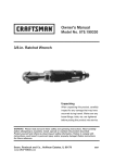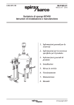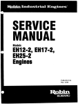
1
V12 Engine Service Manual
CON TENTS
Section
Foreword
I
II
................
................
Page
SRO
Title
...........................................................................
Service Tools& Equipment ...........................................................
Torque Tightening Specifications .......................................................
ii
iii
vi
............... ServiceMaterials ..................................................................... x
IV ............... Service Data .......................................................................
xi
1 ................ General Description ..................................................................
1
1.1 .............. Construction ........................................................................
1
7.2 .............. Full-flow Oilsystem .................................................................
1
1.3 .............. Crankcase Breather ...................................................................
2
1.4 .............. CoolingSystem ......................................................................
2
2
2 ................ Service Procedures ...................................................................
2.1 .............. Sealants ............................................................................
2
3
3 ................ Fault Diagnosis ......................................................................
3.7 .............. Introduction .........................................................................
3
3.2 .............. Diagnostic Procedures ................................................................
3
4 ................ Service Operations ...................................................................
7
4.1 .............. Camshaft. Renew ..............................................
12.13.02-LH ......... 7
111
4.2
..................................
..............
Camshaft Cover Gasket, Renew
..............
Valve Clearance, Check and Adjust
...............................
4.4 .............. Cylinder Head, Overhaul ........................................
4.5 .............. Spark Plug Insert Fitting .........................................
4.6 .............. Drive-plate, Renew ............................................
4.7 .............. Crankshaft Damperand Pulley, Renew ............................
4.8 .............. Crankshaft Front Oil Seal, Renew .................................
4.9 .............. Crankshaft Rear Oil Seal, Renew .................................
4.10 ............. Engine Cover, Renew ...........................................
4.11 ............. Cylinder Head Gasket, Renew ...................................
4.3
4.12
............. Camshaft Sprocket. Renew
12.13.03-RH
12.29.43-LH
......... 7
......... 9
......... 9
12.29.44-RH
12.29.48 ............ I O
............ 11
12.29.78 ............ 16
12.29.21
12.53.13
12.27.01
12.21.74
12.21.20
............ 17
............ 18
............ 19
............20
............ 21
........ 22
12.29.03-RH ........ 22
........................................................... 24
i
72.29.93
12.29.02-LH
Issue 1 August 1994
V12 Engine Service Manual
FOREWORD
This Service Manual has been designed t o enable the skilled Jaguar technician to correctly service and repair the
Jaguar 6.0liter V I 2 engine.
It assumes that the engine has been removed from the vehicle, in accordance with the Vehicle Service Manual, and
is in a clean condition and all service tools and materials are available.
A n index can be found at the rear of the manual.
Issue 1 August 1994
ii
V12 Engine Service Manual
@
S€RVIC€ TOOLS & EQUIPMENT
Jaguar Number
Illustration
18G 55A
0
7
-
7
Description
Piston ring compressor
18G 1432
Valve guide remover /
replacer
18G 1436lA
Crank pulley remover and
timing damper oil
pressure simulator
18G 1465
Engine lifting bracket
c3993
Camshaft timing jig
JD 3 8
Damper setting jig
JD 3 9
Jackshaft setting jig
JD 40
Camshaft sprocket retainer
JD 41
Cylinder sleeve retainers
0
0
iii
Issue 1 August 1994
V12 Engine Service Manual
Illustration
not illustrated
Issue 1 August 1994
Jaguar Number
Description
JD 50
Timing chain tensioner
retainer
JD 128
Crank front seal remover
JD 129
Crank front seal replacer
JD 181
Fuel injection pressure test
kit
JD 183
Quick-fit pipe
disconnecting tool
JD 6118C
Valve spring compressor
JD 61 18C-2
Adapter for valve spring
compressor
MS 53C
Engine support beam
MS 768
Basic handle set
iv
Notes
V12 Engine Service Manual
0
Illustration
Jaguar Numbc
ns 150-8
0
Description
Expandable pilot
AS 204
Valve seat adjustable
cutter
ills 621
Valve seat adjustable
cutter
ills 1519A
Valve spring compressor
ills 1520
Engine stand
AS 1520-1
Engine stand, add-on for
V12 engine
AS 1520-2
Adapter assembly for MS
1520
AS 1520-3
Adapter assembly for MS
1520-1
IA 992
'Snap-On' Oil filter
canister removal tool
Notes
0
not illustrated
V
Issue 1 August 1994
V12 Engine Service Manual
11.
TORQUE TIGHTENING SP€ClFlCATlONS
Fixing
Tightening Torque
(Nm)
Air Cleaner
Hose clamp, hose t o air cleaner and elbow
Air Conditioning Compressor Mounting
3- 4
22 - 28
17 - 23
Adjuster sleeve to mounting bracket
Belt tension bracket to tappet block
I Bracket t o camshaft cover
Compressor to mounting plate
22 - 28
22 - 28
Air Injection Pump
Adjuster bolt to pump
30 - 40
22 - 28
34 - 46
10,5 - 13,5
Adjuster screw to pump
Air pipe assembly setscrew
Air pipe to intake manifold
Check valve
Hose clamp, air pipe to check valve
30 - 40
2,5 - 3.5
Nyloc nut
Pump front mounting bracket bolt
Pump pivot bolt
22 - 28
17 - 23
22 - 28
34 - 4 6
Pump side mounting bracket bolt
I Connecting Rod
50 - 60
I Connecting rod nut
Cooling System
Fan drive unit pulley nut
Fan drive unit pulley stud
13- 17
17 - 23
Fan to fan drive unit
Heater offtake adapter
17 23
32 - 38
-
- 3,5
- 3,5
17 - 23
22 - 28
8,5 - 11,5
17 - 23
17 - 23
22 - 28
Hose clamp, bypass pipe to water pump
Hose clamp, ISCV to tee piece on water housing
2,5
2,5
Inlet spout to water pump
Temperature switch to water rail
1 Water pump assembly screw
I Water pump casing to timing cover
Water pump plate t o timing cover
Water pump t o cylinder block
Water pump t o timing cover
Crankshaft
17 - 23
180 - 220
85- 105
14- 18
8,5 11.5
1 4 - 18
Damper bolt
Drive-plate to crankshaft
I Pulley damper bolt
I Timing disc setscrew
-
I Turning plate to pulley
Issue 1 August 1994
vi
V12 Engine Service Manual
lightening Torque
Fixing
(Nrn)
Cylinder Block
I
I Air iniection .DumD
. connector bracket to cvlinder block
318 in. UNF nut
Bearing caD to cvlinder block (1/2 in. diameter stud)
Bearing
- cap to cylinder block (3/8 in. diameter short stud)
! Bearing cap to cylinder block (318 in. diameter long stud)
Bearing cap to cylinder block (nut)
Cylinder head to cylinder block (7/16 in. diameter stud)
Cylinder head to cylinder block (318 in. diameter stud)
' Oil filter face plug
Oil gallery rear plug
Undershield nut
Cylinder Head and Camshaft Cover
Camshaft bearing cap stud
Camshaft bearing cap to tappet block
Camshaft cover bolt
Camshaft cover screw
~
-
~
I
I
Camshaft position sensor
Coupling assembly to camshaft
Cylinder head to cylinder block (domed nut)
!
-
Tappet block to cylinder head (nut)
Tappet block to cylinder head (socket screw)
Tappet block to cylinder head (stud)
Dipstick Tube
Dipstick tube t o throttle body
4- 5
Drive Chain System
Camshaft position sensor
Chain tensioner setscrew
I
13- 17
10,5 - 13,5
17 - 23
8,5- 11,5
5- 7
22 - 28
64 - 78
34 - 42
22 - 28
13- 17
17 - 23
13- 17
17 23
17 - 23
22 - 28
13- 17
Cylinder head to cylinder block (nut)
Cylinder head to timing cover
Exhaust manifold stud
Exhaust manifold t o cylinder head
Intake manifold stud
Intake manifold to cylinder head
0
5- 7
34 - 46
23 - 31
13- 17
13- 17
76,5 - 93,5
23 31
6- 8
5- 7
85- 115
76,5 - 93,5
5- 7
22 - 28
22 - 28
43 - 57
10,5 - 13,5
22 - 28
22 - 28
Damper assembly upper bracket bolt
Idler shaft retention
Sprocket to auxiliary shaft
Thrust plate to cylinder block
Upper chain tensioner bolt
Engine Mountings
Heatshield t o hydraulic mount
Exhaust Manifold
4- 5
13- 17
17 - 23
34 46
3/8 in. diameter stud
Front heatshield setscrew
Rear heatshield setscrew
-
Fuel rail t o manifold
8,5
vi i
- 11,5
Issue 1 August 1994
V12 Engine Service Manual
Fixing
Tightening Torque
(Nm)
I Generator Mounting
I
Adjuster sleeve to adjuster bracket
Adjuster to generator
Cylinder block to timing cover bracket
34 - 46
17 - 23
17 - 23
43 - 57
Generator mounting bracket pivot bolt
34 - 46
~
Adjuster sleeve nut
Intake Manifold
Top cover mounting stud
Elbow t o intake manifold
Intake manifold stud
8,5-11,5
8,5-11,5
8.5 - 11,5
4- 5
4- 5
Throttle housing to intake manifold
Throttle stop screw locknut
Manifold Ends
Intake manifold connector bracket screw
Manifold end connector assembly
Vacuum take-off screw
7- 10
13- 17
8.5-11,5
Oil Cooler
Hose clamp, oil cooler hose to radiator cradle
Oil cooler pipe clamp plate nut
7- 10
15,5 - 20,5
2,5 - 3,5
Oil cooler pipe connector
Oil cooler pipes to engine
Oil cooler to body
Oil Pump, Filter and Oil Pan
Baffle plate to sandwich t o cylinder block
Clamp bracket setscrew
Cover housing bolt
Cylinder block support bracket setscrew
Delivery elbow to oil pump
Oil filter canister
Oil filter head to cylinder block
Oil pan adapter setscrew
Oil pan drain plug
Oil pan sandwich blanking plate setscrew
Oil pan sandwich to cylinder block
Oil pan to oil pan sandwich
Oil pan to sandwich and cylinder block
Oil pipe bracket setscrew
Outlet elbow bolt
Pipe clamp to pillar nut
Pump assembly t o cylinder block
Rear pipe bracket setscrew
Relief valve assembly
Suction elbow t o oil pump
Taptite screw
Issue 1 August 1994
17 - 23
17- 23
22 - 28
13 - 17
22 - 28
50 - 70
22 - 28
-
13 17
22 - 28
10,5 - 13,5
61 - 7 5
10,5 - 13,5
22 - 28
22 - 28
22 - 28
22 - 28
10,5 - 13,5
22 - 28
22 - 28
22 - 28
102 - 142
22 - 28
5- 7
viii
V12 Engine Service Manual
a
lightening Torque
(Nm)
Fixing
Power Steering
Front and rear plates to mounting bracket
1 Pulley to pump
Pump to engine
Spark Plug and Ignition Coil
22 - 28
22 - 28
22 - 28
10,5 - 13,5
13- 17
Rear coil mounting bracket t o camshaft cover
Spark plug
Starter Motor
-
3,5 4 3
34 - 46
31,5 - 42,5
Bracket clamp Taptite screw
Rear support bracket to cylinder block
Starter motor to cylinder block
1 7iming Cover
Air pump mounting and adjuster bolt
Bearing housing to cylinder block (nut)
Bearing housing to cylinder block (stud)
~
Timing cover plate t o cylinder block
Timing cover to cylinder block
I Timing cover to cylinder head
Transmission Units
Bottom cover to casing
22 - 28
22 - 28
13- 17
22 - 28
22 - 28
13- 17
10,5 - 13,5
9 - 11
37 - 43
58.5 - 71,5
10.5 - 13,5
17 - 23
3.5 - 4,5
21,5 - 28,5
17 - 23
16- 20
41 - 4 9
Bottom cover to flywheel cover
Coupling flange setscrew
Drive-plate to torque converter (setscrew)
Flywheel cover t o cylinder block
Oil pan distance piece to cylinder block
Pipe bracket Taptite screw
Selector lever nut
Transmission pipes t o oil cooler
Transmission pipes t o transmission unit
Transmission unit t o cylinder block
ix
Issue 1 August 1994
V12 Engine Service Manual
Description
Dow 111 silicone grease
UseS
Plug lead to spark plug
Hylosil 102 sealant
Half moon seal to camshaft carrier
Filler cap '0' ring
Loctite 518 sealant
Tivoli Kay adhesive No. 5696
sealant
Vaseline or Silicon 5000
Camshaft carrier to cylinder head
Notes
Or equivalent to Ford Motor
Company Specification
ESE-MlC171-A
Exhaust system joints
Top of oil filler tube
0
0
a
Issue 1 August 1994
X
V12 Engine Service Manual
SERVICE DATA
Engine Data
Application
General
Specification
Item
Uumber of cylinders
Zylinder bank arrangement
12
60 degree vee formation
3ore
Stroke
h b i c capacity
Zompression ratio
90,O mm
78,5 mm
ntake and exhaust
0,30to 0,35 mm
NGK BR7 EF
5993 cm3
11:l
Ignition timing
0
Valve clearance
Spark plug
Ignition coil
Plug lead resistance
rYPe
Sap
rYPe
Uumber per vehicle
'rimarv windina
- resistance
Secondary winding resistance
Secondary winding open circuit
toltage (at engine idle speed)
Zylinder bank A
~
0,65 mm
Nippondenso DIS
2
0.45 to 0.55 ohm
I
1 11,5 to 15,5 kohm (at 20$C)
34 kV (minimum)
1 A 13,24 kohm
2 A 11,64 kohm
3 A 8,48 kohm
L
4 A 7.40 kohm
5A: 8,72 kohm
6 A 14,OO kohm
1B: 8,72 kohm
Zylinder bank B
28: 11,64 kohm
3B: 7,92 kohm
4B: 10,48 kohm
5B: 15,96 kohm
6B: 22,32 kohm
0
(No. 1 cylinder at crankshaft pulley
end. Bank A is right-hand bank
viewed from drive-plate end)
Fuel injection equipment
rYPe
Micro-processor controlled engine
management system
'uel pressure
!xhaust gas analyzer reading (at
mgine idle speed and normal
Iperating temperature)
3 bar
Exhaust Emission
4utomatic transmission
700 RPM (gear selector in neutral)
Idle speed (engine at normal
operating temperature)
0,5% CO maximum (with catalytic
converter fitted)
0
xi
Issue 1 August 1994
V12 Engine Service Manual
Application
:ompression pressure
Item
Cylinder pressure
Specification
13,6 to 16,3 bar (with all spark plugs
removed, throttle fully open, engine
at operating temperature and a
minimum cranking speed of 300
Differential pressure between
cylinders
Zylinder block
Material
Main bearing line bore diameter
RPM.
1,38 bar (maximum)
Aluminum alloy
Zylinder block nominal bore
liameter after honing
For piston grade A
80,429 t o 80,434 mm
89,990 to 90,002 mm
For piston grade B
90,005 t o 90,018 mrn
:ylinder sleeve
Type
Material
Outside diameter (piston grades A
and B)
Slip fit, wet sleeve
Cast iron
97,99 to 98,Ol mm
$1 inder head
Material
Combustion chamber
Material
Number of main bearings
Main bearing type
Journal diameter
Thrust washer thickness
Aluminum alloy
May design, two valves per cylinder
:ran kshaft
Permissible end float
Ionnecting rod
'iston
'iston diameter
'iston ring
Crankpin diameter
Length between centers
Bore for connecting rod bearing
Connecting rod bearing diametrical
clearance
Connecting rod bearing side
clearance
Bore for small end bushing
Type
Skirt clearance
Grade A
Grade B
Number of compression rings
Number of oil control rings
Gap when fitted in bore
'iston pin
Issue 1 August 1994
Cast iron
7
Vandervell VP3
76,215 t o 76,246 mm
2,57 to 2,62 mm
0,075 to 0,279 mm
58.40 to 58,44 mm
151,38 t o 151,50 mrn
62,000 t o 62,014 mm
0,027 to 0,062 mm
0,17 to 0,33 m m
26,98 to 27,005 mm
Solid skirt
0,03 to 0,04 mm
89,960 t o 89,972 mm
89,975 t o 89,987 mm
2
1
Top compression ring: 0.30 to 0,55
mm
Second compression ring: 030 t o
0,50 mm
Oil control ring rails: 0,38 to 1,14
mm
Fully floating
79,25 to 79,38 mm
Grade A(red): 23,809 t o 23,812 mm
Grade B (green): 23,806 to 23,809
mm
Type
Length
Outside diameter
xii
V12 Engine Service Manual
Item
Application
I Number of journals
I Nominal lift
dalve
Permissible end float
Thrust load point
Head diameter (at gauge point)
Valve face angle
Valve stem diameter
Adjustment of valve clearance
dalve guide
Valve clearance
Method
Shim sizes available
Specification
17
19,s mm
10,13 mm
Front end of camshaft
Intake: 41,15 t o 41,40 mm
Exhaust: 34,32 to 34.60 mm
I
1 Intake and exhaust: 45,25 degrees
Intake and exhaust: 7,854 to 7,866
mm
Intake and exhaust: 0,30 to 0,35 mm
1 Shims
' Between 0.085 in and 0.108 in (in
increments of 0.005 in)
I Cast iron
Intake: 48,50 mm
Exhaust: 43,82 mm
Standard - no groove: 12,72 to 12,75
mm
' First oversize - t w o grooves: 12,85
to 12,88 mm
Second oversize - three grooves:
12.98 to 13,Ol mm
I
1
1
'
Material
Length
Outside diameter
~
1
dalve seat
Valve guide bore concentricity with
guide outside diameter
Clearance between valve stem and
cam heel
Within 0,025 mm (i.e.tota1 indicator
reading of 0,050 mm)
8,13 mm (plus the valve clearance)
Seating angle
Valve seat insert outside diameter
dalve spring
Interference fit in cylinder head
Outside diameter
Diametrical clearance
Free length
zamshaft sprocket
zrankshaft sprocket
dler sprocket
liming chain
Number of teeth
Number of teeth
Number of teeth
Type
44,50 to 44.75 degrees
Intake: 42,93 to 42,94 mm
Exhaust: 38,17 to 38,18 mm
Intake and exhaust: 0,09 mm
34.87 to 34.90 mm
0,02 to 0,04 mm
Outer: 53,4 mm
Inner: 44.0 mm
42
21
21
Endless duplex
Number of pitches
Pitch
Roller diameter
Type
At idle speed
180
9,525 mm
6,35 mm
Full flow disposable canister
0.5 bar (minimum)
At 4000 RPM
Type
4,O bar (minimum)
Gilardini Motorfides
rappet
3 1 filter
31 pressure (engine at normal
)perating temperature)
31 pump
xiii
Issue 1 August 1994
V12 Engine Service Manual
0
Drive Belt Tensions
Application
Generator drive belt
Water pump / air injection pump drive belt
Power assisted steering pump /air conditioning
compressor drive belt
Specification
Burroughs method: new belt 775 N. In service if
tension falls below 230 N, reset at 400 N
-Clavis method: new belt 182 t o 188 Hz. In service if
tension falls below 119 Hz, reset at 137 to 143 Hz.
(Measuring point: mid-way between pulleys)
Burroughs method: new belt 650 N. In service if
tension falls below 320 N, reset at 400 N
Clavis method: new belt 169 t o 175 Hz. In service if
tension falls below 127 Hz, reset at 132 to 138 Hz.
(Measuring point: mid-way between crankshaft and air
injection pump pulleys)
Burroughs method: new belt 790 N, rotate engine 3
times (minimum) and reset at 790 N. In service if
tension falls below 270 N, reset a t 630 N
Clavis method: new belt 117 Hz, rotate engine 3 times
(minimum) and reset to 117 Hz. In service if tension
falls below 70 Hz, reset at 90 Hz. (Measuring point:
mid-way between crankshaft and air conditioning
compressor pulleys)
0
0
e
Issue 1 AugUSt 1994
xiv
V12 Engine Service Manual
0
GENERAL DESCRIPTION
-
Set in a 60 degree Vee' formation, the engine has twelve cylinders - six in each bank- each with a bore of 90 mm and
a stroke of 78,5 mm, giving an overall capacity of 5993 cubic centimeters. On each cylinder bank, a single overhead
camshaft actuates two valves per cylinder. Fuel is supplied to each cylinder via a n injector, fed from a regulated fuel
rail. Clean air is supplied via paper element air cleaners on each cylinder bank. To comply with statutory regulations
in some countries and to reduce emissions during the warm-up period, secondary air is delivered t o the exhaust manifolds by an engine-driven air injection pump. This improves oxidation until the catalytic converters are fully effective.
All engine functions are controlled by an integrated engine management system, which incorporates the on-board
diagnostic system (OBDII).
1.1
Construction
The skirted design crankcase is manufactured in aluminum alloy and its open top deck houses slip fit wet cast iron
cylinder sleeves.
Housed in the crankcase is the cast iron crankshaft, which is nitro-carburize treated to give a very high quality finish
on the bearing surfaces and help increase the life of the bearing journals. The crankshaft is supported by seven main
bearing caps, which have bearings of lead bronze on split steel backed shells with a lead indium overlay. Any crankshaft end-float is controlled by halfthrust washers fitted on each side ofthe center main bearing. The gears and pulleys
which drive the timing chain and external drive belts are keyed on t o the crankshaft nose and held captive by a single
bolt fitted into the end of the crankshaft.
The 'H' section connecting rods are of forged steel and have small end bushes of lead bronze with steel backing, which
are machined to size after being pressed intothe connecting rod. Connecting rod bearings are made from lead bronze
on split steel backed shells with lead indium overlay.
Pistons are manufactured from aluminum alloy and are fitted with three rings, two upper compression rings and one
lower oil control scraper ring. The pistons run on hardened steel piston pins, which are offset from the center line of
the piston towards the thrust face.
A major feature of the engine is the design of the aluminum alloy cylinder heads. The heads utilize the'May Fireball'
combustion chamber which by virtue of its design gives better fuel /air mixing and controlled, even burning. These
'lean burn' combustion qualities aid fuel economy and help to meet increasingly stringent emission regulations. The
cylinder heads carry the tappet block (cam carrier) in which the single camshaft per cylinder bank runs directly, with
two steel. in-line valves per cylinder which run i n cast iron guides. Each valve has two valve springs and is operated
by the camshaft via a chilled cast iron bucket tappet and clearance-adjustment shim.
Manufactured in cast iron with chilled cams, the camshafts are retained by machined aluminum caps. The tappet block
is manufactured in cast aluminum alloy and is topped by a cover of the same material.
Camshaft drive is by a single 'duplex' chain, which incorporates an idler sprocket in its drive line. Drive for the chain
is provided by the crankshaft and chain tension is controlled by a tensioner blade and three damper blades.
Three external drive belts situated at the front of the engine are operated by pulleys mounted on the crankshaft nose.
The three belts drive the following:
Generator
Air conditioning compressor and power steering pump
Water pump / cooling fan and air injection pump.
Two windage trays are fitted below the crankcase which prevent oil being sucked up and thrown into the crankcase,
thereby alleviating windage and power loss. Bolted ontothe bottomofthecrankcase is the aluminum sandwich plate,
the front part of which forms the base of the engine, with the rear part opening out t o let oil reach the pressed steel
oil pan. The oil pan is bolted to the sandwich plate.
1.2
Fu//-f/ow Oil System
Oil is drawn from the oil pan via a gauze filter fitted in the suction pipe. Oil is fed under pressure via internal galleries
in the cylinder block to the filter head where it is regulated by a relief valve. Any relief oil is returned directly to the
suction side of the oil pump. The main oil flow is then directed to the oil filter, is again regulated and, in the event of
a blockage in the system, is by-passed. After filtration, the main oil flow passes through a cooler via a regulator, t o
guard against blockage. After cooling, the main oil is fed into the main oil gallery for distribution to various parts of
the engine. Filtered oil is directed under pressure from the main oil gallery to the seven main bearings and then by
oil-ways in the crankshaft, t o the connecting rod bearings. An oil feed pipe connected to the rear of the cylinder block
drawing oil from the main gallery, feeds the camshaft bearings. The idler gear is lubricated with oil from the main gallery by oil-ways drilled at the front of block.
1
Issue 1 August 1994
V12 Engine Service Manual
1.3
Crankcase Breather
'Blow-by' gases are recycled through the air intake system to maintain a crankcase depression, thus preventing their
escape to the atmosphere. Both cylinder banks have identical full and part load breathers. The breather pipes are connected to the top cover plate between the two banks. The other ends of the full load breather pipes are connected to
stub pipes on the intake hoses. The part load breather pipes consist of hoses taken from the full load breather hoses
and are connected to the centre of the intake manifolds. In this way, a suitable depression is maintained at all throttle
settings.
1.4
Cooling System
The engine is cooled in a conventional manner by the circulation of a solution of good quality anti-freeze and water.
The water pump is mounted directly above the crankshaft and is belt driven from the crankshaft by a three point drive,
which also drives the air injection pump. The coolant is fed into the cylinder block by external pipes and is drawn from
the engine via a thermostat in each cylinder bankto the radiator, or directly returned to the engine if the coolant temperature is too low.
2.
SERVICE PROCEDURES
2.1
Sealants
One of the specified sealants for use on this engine is the Marston compound known as Hylosil 102, a white amine cure
system rubber. Should this not be available, an equivalent amine cure sealant must be used. Under no circumstances
should an acidtoxycure system be used. Loctite 518sealant is also specified for certain applications. See Service Materials in the Preliminary Pages for the correct sealant for each application.
Issue 1 August 1994
2
V12 Engine Service Manual
FAU LT DIAGNOSIS
3.1
Introduction
The following diagnostic procedures are provided to assist properly qualified persons to identify and rectify the faults
relating to the engine which are most likely to encountered. Reference is made to the Electrical Diagnostic Manual
(EDM), which should be consulted where necessary. Faults related to the cooling system are dealt with in Section 4.2
and t o the fuel system in Section 5.2 in the appropriate Vehicle Service Manual (VSM).
3.2
Diagnostic Procedures
Symptom
Possible Cause
Check
Remedy
Engine does not start Battery leads loose or ter- Check the condition of the Clean and tighten as necessfails t o rotate)
leads and terminals
minals corroded
ary
Check condition of battery Charge or renew battery as
Battery discharged
with hydrometer
necessary
Starter motor inoperative
ingine rotates but Starter motor speed too low
Nil1 not fire
Faulty ignition system
If the lights dim when ignition
switch is operated, the starter
may be jammed i n starter
ring.
Check for loose and dirty connections to the starter motor
Remove starter motor, free
off pinion and refit
Clean and tighten connections
Check battery leads and ter- Clean and tighten terminals
minals
Check state of battery charge Charge or renew battery as
necessary
Refer to EDM
Rectify as required
Remove the spark plugs
Clean and re-gap the spark
plugs, renew if worn out
Refer t o Fuel System fault
finding in Section 5.2, VSM
Fuel system defect
herheating
herheating at tickiver
Refer to Section 4.2, VSM
Refer to Section 4.2, VSM
-oss of coolant
nsufficient oil pres- Oil requires changing
iure
Worn crankshaft journals
Check oil level and color
Listen for rumble or knock
Excessive crankshaft end- Fit dial gauge and measure
float
Refer t o Section 4.2, VSM
Refer t o Section 4.2, VSM
Change oil and filter
Renew crankshaft
Renew thrust washers
Worn main bearing shells
Listen for rumble
Worn oil pump
Remove oil pump and check Renew oil pump
the clearances
Oil pressure relief valve sticking open
Oil pressure relief valve
spring too weak
Insufficient oil i n oil pan
Engine overheating
Remove valve and check for Renew valve
sticking
Check crankshaft journals for
wear and renew shells
Remove spring and check Renew spring
spring rates
Check oil level
T o p u p as required
Refer to Overheating fault
finding in Section 4.2, VSM
Refer to EDM
Rectify as required
Faulty gauge or sensor
Renew oil and filter
Incorrect grade oil (viscosity Check oil viscosity
too low)
Water in oil
Check oil level and check if oil Renew oil and filter
is a milky white color
Check for leaking head gasket Renew head gasket
3
Issue 1 August 1994
V12 Engine Service Manual
Remedy
Check
Remove oil pan and visually Renew the pump
check
Remove oil pan and visually Remove oil pick-up pipe and
clean strainer
check
Remove oil pan and pipes and Fit new ‘0’ rings
3il pump pipe ‘0’ rings
check
Main oil gallery seals leaking Eliminate other possible Fit new ‘0’ rings or clear oil
gallery
3r gallery blocked
causes
Remove valve and check for Clean or renew the valve
)il pressure too high Selief valve stuck shut
sticking
Remove spring and check the Renew spring
Nrong pressure relief valve
rate
Renew oil and filter
Incorrect grade engine oil Check oil viscosity
[viscosity too high)
Rectify as required
Gauge or sensor fault
Refer to EDM
Refer to Too Cold fault finding
Engine temperature too low
in Section 4.2, VSM
Possible Cause
Symptom
nsufficient oil pres- :racked oil pump housing
ure (continued)
3locked oil pick-up pipe
strainer
3urning oil
iNorn cylinder bores
iNorn valve guides
Worn intake valve seals
Worn piston rings
.osing oil (leaking)
Check wear with a comparator
Insert valve in guide and
check side movement
Rebore cylinders as necessary
Renew valve guides as
necessary
Remove seals and check for Renew in sets
splits or wear
Renew rings in sets and reMeasure rings in bore
bore as necessary
Cylinder head gasket(s) leak- Check for blue smoke from Renew head gasket(s)
exhaust
ing
Renew oil and filter
Incorrect grade of engine oil Check oil viscosity
Wipe clean, run engine and Renew seal
Worn front oil seal
visually check
Wipe bell housing clean, run Renew seal
Worn rear oil seal
engine and visually inspect
for cleanliness
Renew gasket
Visual check
Leaking gaskets
Cylinder block cracked
ixcessive
noise Excessive valve clearance
‘rom valve gear
Broken valve spring(s)
Broken valve guide
Broken valve seat insert
Lack of lubrication
Valve clash
Worn camshaft(s)
Visual check
Check valve clearances
Renew cylinder block
Adjust valve clearances
Remove valves and check
springs
Remove valves and check
guides
Remove valves and check inserts
Check oil pressure gauge reading
Renew as necessary
Renew as necessary
Renew as necessary
Refer t o Insufficient Oil Pres
sure fault finding
Adjust valve timing
Check valve timing
valve clearances.
Check valve clearances and Adjust
Refer t o Insufficient Oil Pres
for lack of lubrication
sure fault finding
Worn camshaft drive chains / Remove front timing cover Renew as necessary
and check for wear
tensioners
Issue 1 August 1994
4
V12 Engine Service Manual
Symptom
Yoisy chains
Possible Cause
Low oil pressure
Tensioners not released
Chains worn
3etonation
(pinking)
Visually check 1 remove and Renew as necessary
check for wear
Visual check
Sprockets worn
Visual check
Tensionerk) worn
knock Ignition timing too far ad- Refer to EDM
vanced
Head gasket(s) leaking
Renew as necessary
Renew as necessary
Rectify as required
Check engine oil level and Renew head gasket(s1
checkfor contamination of oil
I
Pressure test cooling system
and check for contamination
of coolant in header tank
Fuel /air mixture too weak
Engine running too hot
Valve timing incorrect
Rectify as required
Refer to EDM
~
i Refer to Overheating fault
finding in Section 4.2, VSM
Adjust valve timing
Check valve timing
Incorrect grade fuel
Loss of power
Burned valves
' renew valves
Sticking valves
Check cylinder compressions Remove cylinder head(s) and
renew valves / guides or
springs
Poor engine tune
Insufficient valve clearance
Fuel injection fault
Refer to EDM
Check valve clearance
Low compression i n cylinders
Ignition fault
Valve timing incorrect
Partial seizure of engine
Check compressions
Refer to EDM
Check valve timing
Remove spark plugs and rotate crankshaft
Worn camshaft(s)
Remove camshaft(s)
check for wear
Incorrect grade fuel
If all other checks OK this Drain fuel tank and refill with
could be the cause
correct grade fuel
Check cylinder compressions Renew valve, springs or
guides
Check cylinder compressions Renew valve springs and
and for bent valve stems
valves as required
Check cylinder compressions Renew pistons
Refer to Detonation Knock
fault finding
Check cylinder compressions Renew valve
Check cylinder compressions Re-cut or renew valve seat
3ough running at Sticking valves
iormal engine speed
Broken valve springs
Piston fault
Leaking head gasket(s)
Valve burned out
Valve seat burned out
5
Rectify as required
Adjust as necessary
Refer to Fuel System fault
finding in Section 5.2, VSM
Rebore / re-ring as necessary
Rectify as required
Adjust valve timing
Overhaul engine as required
and Renew camshaft(s)
Issue 1 August 1994
V12 Engine Service Manual
Possible Cause
Symptom
3ough running at Ignition fault
iormal engine speed
continued)
3ough idle
Check
Refer to EDM
Fuel injection fault
Refer t o Fuel System fault
finding in Section 5.2,VSM
Air leaking into intake mani- Run engine and check for
leaks / whistling. Spray 'Easy
fold(s)
Start' around suspect area
(the engine speed will increase if an air leak is present)
Visual check
Leaking exhaust
Check valve timing
Valve timing incorrect
Refer to EDM
Incorrect ignition timing
Check cylinder compressions
Valve burned out
Renew gasket(s) or manifold(s)
Ignition fault
Refer to EDM
Fuel injection fault
Zngine backfires
Engine spits
into air boxes
Issue 1 August 1994
Repair leak or renew exhaust
Adjust valve timing
Rectify as required
Renew valve
Rectify as required
Refer to Fuel System fault
finding in Section 5.2, VSM
Repair leaks or renew system
if necessary
Air leakage intolfrom the exhaust system
Leakage past valves and
guides
Checkfor leaksor blows inthe
system
Check for crankcase fumes
and refer to EDM for analysis
of exhaust gases
Ignition timing retarded
Incorrect valve timing
Refer to EDM
Check valve timing
Valves not closing properly
Check valve clearances
Check for wear or gum in Renew guides or decarbonize
the cylinder heads
valve guides
Check for poor seating of Overhaul the cylinder heads
valves
Rectify as required
Refer to EDM
back Excessively weak mixture
Engine fails t o idle
Remedy
Rectify as required
Remove the cylinder head(s)
and overhaul
Rectify as required
Adjust valve timing
Adjust valve clearances
Air leaking into intake mani- Run engine and check for Renew intake tube or gasket
leaks/ whistling. Spray 'Easy
fold(s)
Start' around suspect area
(the engine speed will increase if an air leakis present)
Rectify as required
Refer to EDM
Incorrect ignition timing
Adjust clearances
Valve clearances insufficient Check clearances
Refer to Detonation Knock
Cylinder head gasket(s) leakfault finding
ing
Remove the restrictions or
Blockage in exhaust system Check for restrictions
renew
components
as
necessary
6
V12 Engine Service Manual
SERVICE OPERATIONS
4.1
Camshaft, Renew
SRO
12.13.02 - LEFT-HAND
SRO
12.13.03 - RIGHT-HAND
1
1
1
1
1
Remove the camshaft covers, see Section 4.2.
Remove the idler tensioning pulley assembly from the
right-hand cylinder head.
Rotate the engine to the cam removal position (TDC)until
Timing GaugeC3993can be inserted into the recess inthe
camshaft (Fig. 1).
Note the two uppermost camshaft sprocket retaining
bolts. Remove Timing Gauge C 3993.
Rotate the engine until the two LOWER camshaft sprocket
retaining bolts on the relevant camshaft become accessible.
Push backthe locktabs and remove the two retaining bolts
(ensure that the t a b washer or the bolts do not drop into
the timing case).
Rotate the engine t o the camshaft removal position (TDC)
and refit Timing Gauge C 3993.
Slacken, but do NOT remove the two remaining camshaft
sprocket retaining bolts.
Remove the rubber grommet from the front of the righthand timing cover and insert Service Tool JD 50 (Release
Tool) (1 Fig. 2). and release the locking catch on the timing
chain tensioner.
Fit Service Tool JD 50 (Chain Tension Retainer) (2 Fig. 2)
and retract the timing chain tensioner until the locking
catch is engaged.
Remove Service Tool JD 50.
.
1
0
1
.
1
1
Fia. 1
n
= Removethe remaining two camshaft sprocket bolts and fit
Service Tool JD 40 (1 Fig. 3) to retain the sprocket to the retainer plate.
CAUTION: Do not rotate the engine while the camshaft is
disconnected.
Fia. 3
Issue 1 August 1994
V12 Engine Service Manual
Gradually slacken off each camshaft cap securing nut
(1 Fig. 1)twoturnsat atimeuntil thevalvespringsarefully
relaxed.
Note the cap t o carrier relationship.
Remove the nuts / washers and lift off the bearing caps
(2 Fig. I), and remove the left-hand camshaft (3Fig. 1).
Clean and examine all components thoroughly.
Replace worn or damaged components as necessary.
Ensure that all oilways are clear.
Lubricate the camshaft journals with clean engine oil.
Fit the replacement camshaft to its carrier using Service
Tool, Timing Gauge C 3993,to position the camshaft correctly (Fig. 2).
Fit the bearing caps, washers and securing nuts, (1,2 Fig.
1).
Progressively tighten the securing nuts to the correct
torque working from the center outwards. See Torque
Tightening Specifications in the Preliminary Pages.
Check that Timing Gauge C 3993 is in position.
Engage the camshaft sprocket t o the camshaft, and fit but
do not fully tighten one retaining bolt and tab washer.
9 Remove Service Tool JD 40.
Fit the second retaining bolt to the tab washer, and secure
the t w o bolts.
Remove Service Tool C 3993.
Rotate the engine and fitthe remaining sprocket retaining
bolts and tab washer.
Repeat the procedure for the right-hand camshaft (if
necessary).
Fit Service Tool JD 50 (Chain Tension Retainer) and raise
the timing chain tensioner slightly.
Check and adjust the valve clearances, see Section 4.3.
Lock over all the tabs.
Insert ServiceTool JD 50 (ReleaseTool) throughthetiming
cover. Release the locking catch and allow the tensioner
to expand.
Remove both Service Tools.
= Check the valve clearances, see Section 4.3.
Refit the rubber grommet to the front of the timing cover.
Refit the camshaft covers, see Section 4.2.
Fig. 1
.
.
.
..
..
Issue 1 August 1994
8
Fig. 2
V12 Engine Service Manual
4.2
SRO
Camshaft Cover Gasket, Renew
12.29.43 - LEFT-HAND
SRO
12.29.44 - RIGHT-HAND
= Remove the engine cover, see Section 4.10.
~
Removethe left-hand or right-hand intake manifold as required.
= For right-hand camshaft cover and engine set only:
Remove the idler tensioning pulley assembly from the
right-hand cylinder head. Disconnect the air conditioning
compressor multi-way connector.
Remove and reposition the compressor for access (do
NOT disconnect the manifold or pipework).
For right-hand and left-hand camshaft covers:
Removethe securing nuts and bolts (1 Fig. I),and remove
the camshaft cover.
Remove and discard the gasket (2 Fig. 1) and the halfmoon seal (3 Fig. 1). Clean the mating faces and the halfmoon seal seat.
Apply sealant to the half-moon seal (3 Fig. 1) and seat in
position. See Service Materials in the Preliminary Pages.
Fit and align the new camshaft cover gasket, refit the camshaft cover and secure with nuts and bolts (1 Fig. 1).
For right-hand camshaft cover and engine set only:
Refit the air conditioning compressor.
Reconnect the compressor multi-way connector, and refit
the idler tensioning pulley assembly t o the right-hand cylinder head.
For right-hand and left-hand camshaft covers:
Refit the intake manifold.
Refit the engine cover, see Section 4.10.
9
J12-839
Fig. 1
Issue 1 AUguSt 1994
V12 Engine Service Manual
4.3
SRO
Valve Clearance, Check and Adjusf
12.29.48
Remove the camshaft covers, see Section 4.2.
Rotate the engine as necessary and measure the valve
clearances (2 Fig. 1) between the heel of the cam (4 Fig. 1)
and the cam followers (3Fig. 1).
Make a note of each reading.
Should theclearances be incorrect (see Service Data in the
Preliminary Pages), proceed as follows:
Remove the camshafts, see Section 4.1.
Remove the cam followers (3Fig. 1).
Remove each shim (5 Fig. 1) in turn, check the size with a
micrometer and note the reading.
Calculate the size of shim required following the examples
shown below.
When the correct shim sizes have been obtained, refit
shims and cam followers to the cam carrier.
Lubricate the camshaft journals with clean engine oil.
Refit the camshafts, see Section 4.1.
Recheck the valve clearances.
Refit the camshaft covers, see Section 4.2.
.
.
.
.
.
VALVE CLEARANCES
Excessive Clearance
inches
Size of existing shim
0.100
Plus the actual clearance noted
D
0,119
Less the specified valve clearance
QLU
Required shim size =
0.106
Insufficient Clearance
inches
Size of existing shim
0.107
Plus the actual clearance noted
o.010
0.117
Less the specified valve clearance
QAu
Required shim size =
0.104
Note:
See Service Data in the Preliminary Pages for valve
clearances and available valve shim sizes.
Issue 1 August 1994
10
4
V12 Engine Service Manual
4*4
SRO
Cylinder Head, Overhad
12.29.21
Remove the cylinder head assemblies, see Section 4.1 1.
Note:
Always support the cylinder heads on blocks of
wood. This will prevent damage to the valves
which, when open, protrude below the cylinder
head face.
Remove the spark plugs and exhaust manifolds from the
cylinder head.
Graduallyslacken off eachcamshaftcap securing nut (two
turns at a time) until the valve springs are fully relaxed.
Note the cap to carrier relationship.
Removethe nuts/washers (1 Fig. 1)andIiftoffthe bearing
caps (2 Fig. 1).
Remove the camshaft (3Fig. 1).
= Using a magnet, lift out the cam followers (1 Fig. 2).
Remove thecamshaft carrier and removeall traces of sealant from carrier and head faces.
Remove the valve springs, using Service Tool JD 61 18C
and adapter JD 6118C-2 (Fig. 3).
..
.
0
Fig. 1
~
.
.
w
Fin. 3
11
Issue 1 August 1994
V12 Engine Service Manual
Retrieve the collets (1 Fig. I),collars (2Fig. I), and spring
retaining plates ( 4 Fig. 1).
s Remove the valves (5 Fig. I), noting the relationship between valve and guide to ensurecorrect pairing during reassembly.
Remove the seals from the intake valve guides.
1 Clean all component parts.
= Check for wear and burning of valves or seats.
Check the cylinder head face for distortion.
If distortion is evident, a maximum of 0,025 mm may be removed by skimming the cylinder head.
Taking care not t o damage the inside surface of the combustion chambers, remove all traces of carbon from the intake and exhaust ports.
1
.
212
CAUTION: When using scrapers or wire brushes for removing carbon deposits, avoid scratching the
valve faces and seats. A soft wire brush is the
most suitable implement for this purpose.
1
m*
Fig. 1
Clean all carbon and other deposits from the valve guides
using a suitable valve guide brush.
Thoroughly wash thecylinder head to ensure that all loose
carbon is removed and dry the head with a high pressure
air line.
After cleaning and polishing each valve, examine the
stems for straightness and wear, using a suitable dial
gauge and vee-block see example at Fig. 2.
Examine the valve faces for burns, pitting and distortion.
Renew any valves that are excessively worn, bent, or too
badly pitted to be salvaged by refacing.
U: No attempt should be made t o clean up a burnt or
.
*
badly pitted valve face by extensive ’grinding in‘ of
the valve to the seat.
Lightly lap the valves into the seats with a fine grinding
compound. The reseating operation should leave thefinished surfaces smooth. Excessive lapping will groove the
valve face resulting in a poor seat when the engine is hot.
Fig. 3 shows:
’A’ - Correctly seated
‘B’ - Undesirable condition
‘C-Method of rectification.
To testthevalvesforconcentricity withtheirseats,coatthe
face of the valve with Prussian blue or similar and rotate
the valve against the seat.
If the valve face is concentric with the valve stem, a mark
will be made all around the face.
.
A
. . .
‘ I
Fig. 3
Issue 1 August 1994
12
L
-
C
V12 Engine Service Manual
Should a mark be made on only one side of the face, the
face is not concentric with the valve stem.
Clean the valve and again coat with Prussian blue and rotate the valve against the seat.
Check that the valve guide is concentric with the valve
seat, if not, the seat must be recut.
Whenever valves are replaced, the seats must be recut
prior to lapping of the valves.
Check valve guide wear by inserting a new valve into the
guide to be checked, lift it 6 mm from its seat and rock it
sideways. Movement of the valve across its seat must not
exceed 0,5 mm (A Fig. 1).
Should the movement exceed this tolerance, the valve
guide must be replaced. Use Service Tool 18G 1432 to drift
out the old guide (Fig. 2). Ensure that the relevant valve
guide is selected prior to fitting.
When new guides are to be fitted they should always be
one size larger than the old guide.
Cylinder head bores will require reaming as follows:
Removethe old valve guide and ream the cylinder head to
the relevant dimension. Immerse the cylinder head in
boiling water for 30 minutes. Coatthe guide with graphite
grease, and, using ServiceTool 18G 1432 (1 Fig. 31, drift in
the guide from the camshaft side until the snap-ring is
seated in the groove.
.
=
9
.
Note:
A
..
112 259
Fig. 1
The interference should not be sufficient to require
the use of excessive force when fitting the guide.
After fitting a valve guide, the valve seat must be recut
using Service Tool MS 621.
Examine the valve seat inserts for pitting or excess wear.
If renewal is necessary, proceed as follows:
Remove the inserts by machining, leaving approximately
0,25 mm of metal which can easily be removed by hand
without damaging the cylinder head.
Measure the diameter of the insert recess in the cylinder
head.
Grind down the outside diameter ofthe new insert to a dimension 0,08 mm larger than the insert recess.
Heat the cylinder head for 30 minutes from cold to a temperature of 15OoC (3OOOF).
Fit the insert ensuring that it beds evenly i n the recess.
When the cylinder head has cooled, re-cut the valve seat
using Service Tool MS 621.
,
.
-
__
Fia. 2
.
Fig. 3
13
kSUe
1 August 1994
V12 Engine Service Manual
If new valve inserts have been fitted, the clearance
m: between
valve stem and cam must be checked. See
Service Data in the Preliminary Pages.
9
The dimension must be taken between the valve stem and
the back of the cam.
Should this dimension not be obtained, metal must be
ground from the valve seat of the insert.
.
m: Use only suitable grinding equipment.
Remove only very small amounts of metal from the valve
seat at one time before re-checking the clearance.
Examine the cam followers for wear on the top face, these
should be perfectly flat. Checkfor any sign of barreling on
the side faces (Fig. 1). Replace all followers that are worn
or suspect.
Wash the valves, springs, collets, and cam followers and
air dry.
After the valve springs have been thoroughly washed,
they must be examined for fatigue and distortion. Renew
as necessary.
Test the valve springs either by comparison with the figures given in DATA, or by comparison with a new valve
spring (using a recommended valve spring testing machine).
To test against a new valve spring, insert both valve
springs end to end between the test equipment. Apply a
load to partly compress the springs and measure their
comparative lengths (Fig. 2).
.
Fig. 1
b:‘A’ is the old spring.
lfthe distance at ‘A’ is smallerthan the distance at ‘B’, then
‘A’ must be replaced.
Spring distortion is determined by positioning the spring
upright on a surface plate and checking the squareness of
each end with a set square (Fig. 3).
All valve springs which have diminished in length and / o r
are not square must be renewed. Fit the valves into the
guides and place the cylinder head on wooden blocks.
Fit the valve spring seats, intake valve guide oil seals,
springs and collars.
Compress the springs using ServiceTool JD6118C and insert the split collets.
Apply sealant to the camshaft carrier’s mating surface and
refit the camshaft carrier. See Service Materials in the Preliminary Pages.
.
.
.
.
112 m
I
Fig. 2
J 12 276
Fig. 3
Issue 1 August 1994
14
V12 Engine Service Manual
1
Refit the original shims in the valve collar recesses
(1 Fig. 1).
Ensure that the shims are seated correctly, and fit the cam
followers.
&-&:
1
If the cylinder head has been overhauled to the extent of having the valve seats recut, each shim
should be 0.010 in. smaller than the original.
Lubricate the camshaft and fit t o the camshaft carrier ensuring that it is fitted with the slot to the top.
Fit the bearing caps, washers and securing nuts (1,2 Fig.
2).
Progressively tighten the securing nuts to the correct
torque working from the center outwards. See Torque
nghtening Specifications in the Preliminary Pages.
Check and adjust the valve clearances. See Section 4.3.
.
1
1
Note:
1
1
1
1
Afinal check of the valve clearances should be done
when the cylinder head i s fitted and tightened to the
cylinder block.
/
/
I
I
Fia. 1
Clean the cylinder head thoroughly and check the cylinder
head and cylinder block for warping, bowing or cracks.
Ensure that the cylinder head and block mating faces are
clean and all oil /water galleries are not obstructed.
Repeatthe overhaul procedure for the right-hand cylinder
head.
Refit thecylinder head assemblies, see Section 4.11.
Fia. 2
15
Issue 1 August 1994
V12 Engine Service Manual
4.5
.
SRO
Spark Plug Insert Fitting
12.29.78
Remove the appropriate cylinder head, see Section 4.1 1.
Note: Always support the cylinder heads on blocks of
wood. This will prevent damage to the valves
which, when open, protrude below the cylinder
head face.
Remove the valves, see Section 4.4.
Bore out the stripped thread to 19.05 mmdiameterand tap
out to 16 UNF - 28 (Dimension 'A' Fig. 1).
Counter-bore to 24,13 mm (Dimension 'B').
Dimension 'C' = 22,23 mm.
Dimension 'D' = 14,22 mm - 14,48 mm.
Dimension 'E' = 10,78 mm.
Dimension 'F' = 15,75 mm.
Dimension 'G' = 11,81 mm - 11,94 mm.
Fit the screwed insert ensuring that it sits firmly at the bottom of the thread.
Drill and ream a 3,17 mm diameter hole 2,83 mm deep, between the side of the insert and the head.
Drive in a locking pin and secure by peening the edge of
the insert and the locking pin.
Dimension 'H' = 10,16 mm (Fig. 2).
Refit the valves, see Section 4.4.
Refit the appropriate cylinder head, see Section 4.11.
.
.
Fig. 1
.
9
Fig. 2
Issue 1 August 1994
16
V12 Engine Service Manual
Drive-plate, Renew
..
SUO
12.53.13
Remove the torque converter.
Fit a suitable wedge to prevent the drive-plate rotating
and remove the drive-plate securing bolts (1 Fig. 1) and
discard them.
Remove the drive-plate and the reinforcing ring.
Clean and examine all components, renew as necessary.
Thoroughly clean all mating faces.
Fit the replacement drive-plate and the reinforcing ring,
and secure with the bolts.
Refit the torque converter.
..
.
.
Fig. 1
17
Issue 1 August 1994
V12 Engine Service Manual
4.7
.
SRO
0
Crankshaft Damper and Pulley, Renew
12.21.01
Remove the drive belts.
Remove the pulley securing bolts (1, 2 Fig. 1) and withdrawthe crankturning plate (3 Fig. l),spacers (4 Fig. 1)and
the pulley (5 Fig. 1).
Fit a suitable wedge to the drive-plate, and remove the
crankshaft damper bolt (6 Fig. 1). Alternatively, Service
Tool 18G 1205 with longer screws and spacers may be
used (Fig. 2).
Use Service Tool 18G 1436A to remove the crankshaft
damper assembly (Fig. 3).
Remove the timing disc (7 Fig. 1) from the damper (8 Fig.
1).
Clean and examine all components for wear and damage,
and renew as necessary.
Fit the timing disc (7 Fig. 1) to the replacement damper (8
Fig. 1) with the roll pin (9 Fig. 1) and secure with the screws
(10 Fig. 1).
Fit the damper assembly to the crankshaft nose, and secure with the damper bolt (6 Fig. 1).
Fit the pulley (5 Fig. 1) and the crank turning plate (3 Fig.
1) and secure with the securing bolts and spacers (1,2,4
Fig. 1).
Refit the drive belts.
.
m
9
112-851
1
4
Fig. 1
0
.
Fig. 2
0
112.789
Fig. 3
Issue 1 August 1994
18
V12 Engine Service Manual
e
4.10
.
SRO
Engine Cover, Renew
12.29.93
Rotate the four turn-fasteners ‘/4 of a turn anti-clockwise
and remove the engine cover (Fig.1). Removethe four fastener sockets from the fuel rail.
Fit four new fastener sockets to the fuel rail, position the
new engine cover, and secure the four fasteners by thumb
pressure into the sockets.
.
Fia. 1
21
Issue 1 August 1994
V12 Engine Service Manual
4.11
Cylinder Head Gasket, Renew
SRO
12.29.02 -LEFT-HAND
SRO
12.29.03 -RIGHT-HAND
Drain the cooling system, see Section 4.2 and depressurize
the fuel system, see Section 5.2 (these sections are in the appropriate Vehicle Service Manual). Disconnect the exhaust
system with the vehicle supported on axle stands. Remove
components as required for access to the cylinder head and
proceed as follows.
Remove the sprocket from the camshaft, see Section 4.12.
Remove the front cover securing nuts.
Release the cylinder head retaining nuts,
in. domed
and 3/8 in., and remove the cylinder head-assistance may
be required.
..
m: During the cylinder head removal, reposition the
camshaft oil feed pipe for access.
Note:
.
.
_-
Jll-593
Fia. 1
Remove and discard the cylinder head gasket.
Fit cylinder sleeve retainers, Service Tool JD 41 (Fig. 1).
Removethe breather housing to cylinder head gasket, and
water rail to cylinder head gaskets.
1
Note:
.
1
Always support the cylinder head on blocks of
wood. This will prevent damage to the valves
which, when open, protrude below the cylinder
head face.
Clean all jointing faces. Always fit new gaskets and
seals on assembly.
Check that the other camshaft is still at TDC using Service
Tool C 3933 (Fig. 2).
Remove the cylinder sleeve retainers Special Tool JD 41,
(Fig. 1).
Fit and align the new cylinder head gasket.
Fit and align the cylinder head ensuring that pipes or
cables/ harnesses are not trapped - assistance may be required.
Fit and tighten the cylinder head securing nuts with reference to the sequence shown in Fig. 3. See Service Data in
the Preliminary Pages for the correct torque figures.
.
m
I
Fig. 2
14
Fig. 3
Issue 1 August 1994
22
I
Crankshafl Front Oil Seal, Renew
SRO
1
1
1
1
1
1
1
1
12.21.14
Remove the crankshaft damper assembly and pulley, see
Section 4.7.
Remove the crank damper woodruff key (Fig.1).
Prize the seal f r o m the timing cover using a screwdriver
(Fig. 2).
Discard the seal and withdraw the crankshaft spacer
(Fig.1).
Examineall componentsforwear and damage, and renew
as necessary. Ensure that the seal recess is absolutely
clean.
Smear the new seal with clean engine oil.
Position the seal squarely in the recess and seat using Service Tool JD 129, and crank bolt (Fig. 3).
Refit the crankshaft spacer and the woodruff key.
Refit the crankshaft damper assembly and pulley, see Section 4.7.
Fig. 1
Fig. 2
Fig. 3
19
Issue 1 August 1994
V I 2 Engine Service Manual
4.9
SRO
1
1
1
1
Crankshaft Rear Oil Sea/, Renew
J
12.21.20
Remove the drive-plate, see Section 4.6.
Clean and lubricate the exposed surfaces ofthe crankshaft
andthe insidesurfacesofthetool body,(removal /installstion tool - JD 163) with clean engine oil.
Locatethetool bodyonthecrankshafttoabuttheseal rear
face, which is located flush with the rear of the crankcase.
Align both holes through the tool body with the threaded
holes in the crankshaft rear flange, screw both bolt assemblies (2 Fig.1) into them to lock the tool body t o the crankshaft.
Place the center punch (1 Fig.1) through one of the tool
body's outer three holes and note the distance by which
the shoulder of the punch stands proud.
Using a hammer (Fig.l), penetrate the seal (up to 2 mm);
determine this from the distance noted in the previous
operation.
CAUTION: Do not exceed 2 m m depth.
1
1
? I 2 b73
Fia. 1
Remove the punch and insert the self-tapping screw (1 Fig.
2); turning it no more than 1'/2 turns.
Repeat the procedure for inserting the two other screws.
0
CAUTION: Do not exceed 2 turns or the screw may break.
m
1
1
1
Remove the two bolt assemblies, so that the center bolt (2
Fig. 2) can be turned clockwise t o extract the seal.
Remove and discard the seal from the tool.
Clean the surface ofthe crankshaft and ensure it issmooth
and free of damage. Lubricate the surface with clean engine oil.
Fit the new seal squarely onto the crankshaft using the
guide supplied with the seal.
CAUTION: The seal guide must not be separated from the
seal prior t o fitment or it will be rendered unsuitable for use.
1
1
Refit the tool body onto the crankshaft to abut the seal rear
face. Align the holes through the tool body with the
threaded holes in the crankshaft flange, insert both bolt assemblies and screw them in until the bolts 'bottom'.
Remove the seal guide. Tighten the nuts / washers alternately against the tool face, '/2 turn at a time, until the seal
casing is driven into its location in the crankcase by the
front rim of the tool.
Remove the bolt assemblies, and remove the body of the
tool from the crankshaft.
Refit the drive-plate, see Section 4.6.
Issue 1 August 1994
20
Fia. 2
V12 Engine Service Manual
e.
.
..
.
Fit and tighten the cylinder head to front cover securing
nuts.
Remove the sprocket retaining tool - Service Tool JD 40
(1 Fig. 1).
Refit the sprocket to the camshaft, see Section 4.12.
Check, and if necessary adjust, the valve clearances, see
Section 4.3.
Refit the rubber grommet t o the front cover.
Replace the components removed for access and reconnect
the exhaust system with the vehicle supported on axle
stands. Fill the system with coolant, see Section 4.2 in the
appropriate Vehicle Service Manual.
Fig. 1
23
Issue 1 August 1994
V12 Engine Service Manual
4.12
m
Camshaft Sprocket, Renew
Rotate the crankshaft until the required camshaft is 180°
from TDC, and remove two camshaft securing bolts (ensurethat neitherthe bolts northetab washer drop into the
timing case.
Rotate thecrankshaft until thecamshaft is atTDC and align
using Service Tool C3993 (Timing Gauge) (Fig. 1).
Slacken but do NOT remove, the two remaining bolts.
Remove the rubber grommet from the right-hand front of
the timing cover, insert Service Tool JD 50 (1 Fig. 2), and
release the locking catch on the timing chain tensioner.
Fit Service Tool JD 50 (ChainTension Retainer) ( 2 Fig. 2)t o
the right-hand camshaft, and retract the timing chain tensioner until the locking catch is engaged.
Remove Service Tools JD 50.
Remove the remaining two left-hand camshaft sprocket
bolts and fit Service Tool JD 40 (1 Fig. 3) to secure the
sprocket to the retainer plate.
CAUTION: Do not rotate the engine while the camshaft is
disconnected.
Fia. 1
n
Fig. 3
Issue 1 August 1994
24
V12 Engine Service Manual
e
1
1
1
Engage the camshaft sprocket (1 Fig. 1) t o the camshaft.
Release the chain tension by fitting Service Tool JD 50
(chain tension retainer) (2 Fig. 2). raising the timing chain
tensioner slightly, and then insetting Service Tool JD 50
(ReleaseTool) (1 Fig. 2) through the timing cover and releasing the locking catch which allows the tensioner t o expand.
Remove both Service Tools.
Check that the camshaft is still at TDC using Service Tool
C 3933 (Fig. 3).
Remove the snap-ring (3 Fig. 1).
Reposition the coupling (4 Fig. 1) to align the retaining
holes, and refit the snap-ring (3Fig. 1).
Fit but do not fully tighten one retaining bolt (5 Fig. 1) and
new tab washer (6 Fig. 1).
Fit the second retaining bolt t o the tab washer, and secure
the two bolts.
Remove the timing gauge, Service Tool C 3993 (Fig. 3).
Rotate the engine and fit the remaining sprocket retaining
bolts and new tab washer.
Lock over all the tabs.
Re-check the camshaft timing, using Service Tool C 3993
(Fig. 3).
.
.
..
.
1
1
1
Fia. 1
n
Fig. 3
25
Issue 1 August 1994
26
Index
F
Fault diamosis
Diagnostic procedures, 3
Introduction, 3
Foreword, ii
G
General description
Construction, 1
Cooling system, 2
Crankcase breather, 2
Full-flow oil system, 1
S
Service materials, x
Service operations
Check & adjust, Valve clearances, 10
Fitting, Spark plug insert, 16
Overhaul, Cylinder head, 11
Renew
Camshaft, 7
Camshaft cover gasket, 9
Camshaft sprocket, 24
Crankshaft damper & pulley, 18
Crankshaft oil seal
Front, 19
Rear, 20
Cylinder head gasket, 22
Drive plate, 17
Engine cover, 21
Service procedures, Sealants, 2
Service tools & equipment, iii
T
Torque tightening specifications, vi
27
Issue 1 August 1994
28