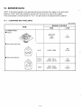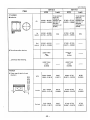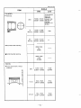
1
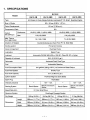
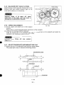
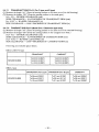
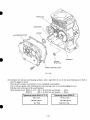
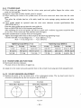
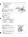
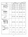
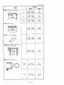
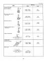
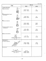
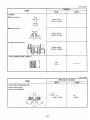
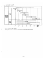
CONTENTS
Section
1
2
.
.
3.
4
.
4-1
4-2
4-3
4-4
4-5
4-6
4-7
4-8
4-9
4-10
4-11
4-12
4-13
4-1 4
4-15
4-1 6
4-1 7
5.
6
7
8
.
.
.
Title
Page
m Feed
I.SPECIFICATIONS
~~
~
~~~
~
~
~~
~~
~~~
EH12-2B
~~~
~
~
EHl2-2D
EH12-2DS
EH12-2BS
Air-Cooled, 4-Cycle, Single-Cylinder, HorizontalP.T.O. Shaft, Gasoline Engine
TYPe
60 x 43 rnm (2.36 x 1.57 in.)
Bore X Stroke
121 cm3 (7.38 cu.in.)
Piston Displacement
Max. Torque
Nem (kaf*m)/rDm
7.5 (0.76) /2600
15 (152)/1300
CounterclockwiseAs Viewd From P.T.O. Shaft Side
Direction of Rotation
Cooling system
Forced Air Cooling
Valve Arrangement
Overhead Valve
Lubrication
~~
~~
EH12-2
Model
I
~~~~
Splash Type
~
~~~~~
~~
~
~~
~
Automobile Oil SAE #20, #30 or 1OW-30 ; Class SE,SF or higher
Lubricant
Capacity of Lubricant
I Carburetor
I Fuel
0.6 L (0.16 U.S. gal.)
I
I
Type
Float
Draft,
Horizontal
Gasoline
Automobile
~~~~~~~
~~
~
~~~
310 g/KW*h (230gr/HP*h) At Continuous Rated Output
I Fuel
I
Type Gravity
Fuel Tank Capacity
3.6 L (0.95 U.S. gal.)
Flywheel Magneto (Solid State) Ignition System
I Spark Plug
NGK BGES
Charging Capacity
-
-
12V - 1.3A
Recoil and Electric
Recoil Starter Starting System
Starter
I Speed Reduction
Starter
Recoil
and
Centrifugal Flyweight System
15.5 kg(34.2Ib.)
Length
Recoil Starter
2:l Cam Shaft Drive
Governor System
Dry Weight
12V - 1.3A
299 mm (11.77 in.)
I
18.0 kg (39.7Ib.)
I
15.0kg(33.1Ib.)
I
17.5 kg (38.6Ib.)
I 299 mm (11.77 in.) I 297 mm (11.69 in.) I 297 mm(ll.69 in.)
330mrn (12.99in.)
341 mm (13.43in.)
366 mm (14.41 in.) 366 mm (14.41 in.)
-1-
El
EH17-2
Model
Air-Cooled, 4-Cycle, Single-Cylinder, HorizontalP.T.O. Shaft, Gasoline Engine
TYPe
~~
~~
~~
~~~~
~
~
67 x 49 mrn (2.64X 1.93 in.)
Bore X Stroke
172 cm3(10.50cu.in.)
Compression Ratio
Output
Kw (HP)/rpm
EH17-2DS
EH17-2D
EH17-2BS
EH17-2B
.
8.5
Continuous
2.6 (3.5)/ 1500 2.9 (4.0) / 1800
/3000 2.9 (4.0) /3600
2.6 (3.5)
4.4 (6.0) /2000
4.4 (6.0) /4000
Max.
Max.Torque
10.7 (1 -09)/ 2600
21.4 (2.1 8)/ 1300
Nom (kgf*m)/rpm
I
I
Direction of Rotation
CounterclockwiseAs Viewd From P.T.O. Shaft Side
I
I Arrangement
Valve
I
I
I
systemCooling
I Lubrication
~
~~
Forced Air Cooling
~~
Overhead Valve
Type
~~
Splash
~~~~~~~
~ _ _ _ _ _
~
_____
~
~
~
Automobile OilSAE #20, #30 or 1OW-30 ; Class SE, SF or higher
Lubricant
Capacity of Lubricant
0.65 L (0.17
Horizontal
Fuel
U.S.gal.)
Draft,
Float
Type
Carburetor
Automobile Gasoline
Fuel Consumption Rate
310g/KW-h (230 gr/HP*h) At Continuous Rated Output
Fuel Feed System
Gravity Type
Fuel Tank Capacity
3.6 L (0.95 US. gal.)
Flywheel Magneto (Solid State)
Spark Plug
I
NGK B6HS
Charging Capacity
-
12V - 1.3A
-
12V - 1.3A
Starting System
Speed Reduction
-
2:l Cam Shaft Drive
Centrifugal Flyweight System Governor System
Dry Weight
16.5 kg (36.4 Ib.)
Length
Dimensions
Width
Height
301 mm (11.85 in.)
mm (12.99in.)
380mm (14.96in.)
19.0 kg (41.9Ib.)
mrn (1 1.85 in.)
16.0 kg (35.3 Ib.)
18.5 kg(40.8 Ib.)
299 mm(ll.77in.)
299 mm (11.77 in.) 301
330 rnm (12.99in.)
341 rnrn (13.43in.) 330
341 rnm (13.43in.:
380rnm (14.96in.)
380rnm (14.96in.:
-2-
380mm (14.96in.)
~~~~~~
~~
~
EH25-2
Model
EH25-2 6
EH25-2DS
EH25-2D
EH25-26s
Air-Cooled, 4-Cycle, Single-Cylinder, HorizontalP.T.O. Shaft, Gasoline Engine
TYPe
Bore x Stroke
75 X 57 mm (2.95X 2.24 in.)
Piston Displacement
251 cm3(15.31 cu.in;)
8.5
Compression Ratio
Continuous
output
Kw (HP)hm
4.0 (5.5) I 1500 4.7 (6.4) / 1800
4.0 (5.5)/3000 4.7 (6.4) /3600
6.3 (8.5)/2000
6.3 (8.5)/4000
33.1 (3.38) / 1300
16.6 (1.69)/ 2600
Max.
Max. Torque
Nom (kgf*m)/rpm
Direction of Rotation
I
Counterclockwise
Viewd
As
From
Cooling system
P.T.O.
Shaft
Side
Forced Air Cooling
Valve Arrangement
Overhead Valve
Lubrication
Splash Type
Automobile Oil SAE#20, #30 or 1OW-30 ; Class SE,SF or higher
1.O L (0.26 U.S. gal.)
Capacity of Lubricant
~
Carburetor
~~~
~
~
~
~~~~~
Horizontal Draft, Float Type
Fuel
Automobile Gasoline
Fuel Consumption Rate
310 g/KW*h (230 gr/ HP-h) At Continuous Rated Output
Gravity Type
Fuel Feed System
6.0 L (15 9 U.S. gal.)
Fuel Tank Capacity
Ignition System
Flywheel Magneto (Solid State)
NGK B6HS
Spark Plug
-
12V - 1.3A
-
Recoil Starter
Recoil and Electric
Starter
Recoil Starter
Charging Capacity
Starting System
IDrive
I
Reduction
Speed
System
Governor
Dry Weight
1
I
Shaft
2:l Cam
12V - 1.3A
Recoil and Electric
Starter
-
System
Flyweight
Centrifugal
24.0 kg (52.9Ib.)
I Length
28.0 kg (61.7 Ib.)
333mm (13.11 in.) 333mm (13.11 in.)
23.0 kg (50.7 Ib.)
27.0 kg (59.5 Ib.)
332mm (13.07in.)
~~~
Dimensions
Lubricant
332mm(l3.07in.)
~~
Width
380mm (14.96in.)
380mm (14.96in.)
380mm (14.96in.)
380mrn (14.96in.)
Height
440mm (17.32in.)
440mm (17.32in.)
440mm (17.32in.)
4 4 0 m m (17.32in.)
-3-
2-1 MAXIMUMOUTPUT
The maximum output is the output of an engine with its throttle valve fully opened under the condition
that all the moving parts are properlyworn in after the initial break-in period.
A new engine may not produce full maximum output while its moving parts are still not broken-in.
2-2 CONTINUOUS RATED OUTPUT
Thecontinuousratedoutputistheoutput
of anengineatoptimumgovernedspeedwhichismost
favorable from the view pointof engine’s life and fuel consumption.
is installed on a certainequipment, it is recommendedthatthecontinuousoutput
Whentheengine
required from the engine be kept below this continuous rated output.
2-3 MAXIMUM TORQUE
The maximum torque is the torque at the output shaft when the engine is producing maximum output at
certainrevolution.
- 4 -
8
2-4 PERFORMANCECURVES
0 EHlPD, B
for
B type
HP kW
4
3
l2
2
3
+
n
+
3
1
0
1
0
2000
(1000)
-
3000
(1 500)
REVOLUTION
r.p.m.
- 5 -
4000
(2000)
0 EH17D, 6
for B tvDe
N . m kgfam
-
3000
(1000)
(1500)
REVOLUTION
-6-
r.p.m.
4000
(2000)
EH25D, B
N . m kgf-m
r
I
I
I
I
I
"
I
I
"
-I
I
MAXIMUM TORQUE AL\
"
I
HP
kW
I
I
I
1.7 (3.4)
16.5 (33)
1
I
I
I
I
1.6 (3.2)
15.5 (31)
1.5 (3.0)
14.5 (29)
1.4 (2.8)
I I MAXIMUM HORSEPOWER'(NET)
I
8 - 6
7
t:
5
c
4
I
RECOMMENDED
$4
I-
&
2
I
1
i
0
2000
(1 000)
-
3000
'
(1500)
REVOLUTION
-7-
r.p.m.
4000
(2000)
3. FEATURES
,,
1. The overhead valve design offers
a compactness, light weight and ideal combustion characteristics
resulting in more power from Iess fuel and prolonged engine life.
2. An optimum lubrication and better tilted operation thanks to upright cylinder design.
3. A crossflow arrangement of intake and exhaust ports ensures stable performance under high ambient
temperature.
4. Theautomaticdecompressiomsystemlightens
the recoilpull
force by 40% comparingtothe
conventional SV engines.
5. An easy operation thanks to integrated engine control system.
Improved throttle mechanism is adopted for easy starting.
6. Combustion and mechanical noises have been analyzed acoustically and improved for better tonal
quality and lower engine noise.
7. Optimallydesignedreciprocatingpartsreducethevibrationlevel
of theengine. EH25-2 engine
equips single through-balancer shaft as an option.
4. GENERAL DESCRIPTION OF ENGINE COMPONENTS
4-1 CYLINDER AND CRANKCASE
The cylinder and crankcaseis single piece aluminum
diecasting. The cylinder liner, made
of special cast
iron, is molded into the aluminum casting.
The crankcase has a mounting surface. on the output
shaft side, where the main bearing cover is attached.
/"-
\
Fig. 4-1
4-2 MAIN BEARING COVER
The main bearing cover is an aluminum diecasting,
which is mounted on theoutputshaftside
of the
crankcase.
Remove the main bearing cover to inspect the inside
of the engine.
The pilots and bosses are machined on the cover for
direct mounting of the engine onto such machines as
generators and pumps.
Oil gauge (fillers) are on both sides of the cover for
easy maintenance.
/"
OIL GAUGE
OIL GAUGE
Fig. 4-2
- 8 -
W
4-3 CRANKSHAFT
The crankshaft is forged carbon steel, and the crank
induction-hardened.
pin
is
The output end of the shaft has a crankshaft gear, and
EH25-2 whicharepressedinto
balancergearfor
position.
B TYPE
D TYPE
Fig. 4-3
4 4 CONNECTING ROD AND PISTON
The connecting rod is an aluminum alloy diecasting,
and its largeandsmalIendsfunctionasbearings.
The piston is an aluminum alloy casting, and carries
two compression rings and oneoil ring.
I
f i g . 4-4
4-5 PISTONRINGS
The piston rings are made of special cast iron.
Theprofile of thetopring
is barrelfaceandthe
second ring has a taperedface.
The oil ringconsists of acutterring
anda
coil
expander for better sealing and less oil consumption.
TOP RING
SECOND RING
OIL RING
f i g . 4-5
-9-
4-6 CAMSHAFT
Thecamshaft
for theD-typeengine
ismade
of
special cast iron and camshaft gears are casted together in one piece.
Both sides of the shaft fit into the plane bearings on
the crankcase and main bearing cover.
ThecamshaftfortheB-typeengineismade
of
forged carbon steel and also functions as PTO shaft.
The cam gear is press fitted on the shaft and the ball
bearings are employed on both sides for supporting
the shaft.
B TYPE
D lYPE
Fig. 4-6
4-7 VALVE ARRANGEMENT
The intake valve is located on flywheel side of the
cylinder head.
The hard alloy valve seatsaxe molded in the cylinder
head and stellite is fused to the exhaust valve face.
The cylinder baffle leads cooling air to the exhaust
valve area for the optimum cooling.
n
INTAKE
/
Fig. 4-7
4-8 CYLINDER HEAD
The cylinder head is an aluminum die casting which
utilizeswedge
type combustionchamber
for the
highest combustion efficiency.
Fig. 4-8
- 10 -
4-9 GOVERNORSYSTEM
The governor is a centrifugal flyweight type which
ensuresconstantoperationattheselectedspeed
against load variations.
The governor gear with governor weights is installed
on the main bearing cover.
4-10 COOLING SYSTEM
Thelargefinsontheflywheelprovidesufficient
coolingaircapacity
for theinletandexhaustarea
and cylinder.
The cylinder baffle helps the cooling air flow efficiently.
/
GOVERNOR GEAR
Fig. 4-9
4-1 1 LUBRICATION
All
the
rotating
and
sliding
parts
are
splashlubricated by the oil scraper on the connecting
rod.
I
OIL SCRAPER
Fig. 4-10
4-1 2 -IGNITION SYSTEM
Theignitionsystemis
atransistorcontrolledmagneto ignition system which cosists of a flywheel and
an ignition coil witha built in transistor.
This system has an ignition timing advance for easy
starting.
Fig. 4-1 7
- 11 -
4-13 CARBURETOR
Theenginesareequippedwithahorizontaldraft
carburetor that has a float controlled fuel system and
a fixed main jet.
Thecarburetors
are calibratedcarefullyforeasy
starting,goodacceleration,lowfuelconsumption
and sufficient output.
4-14 AIR CLEANER
The air cleaner is a single urethane foam element system. As an option, heavy duty type with
element type is available.
a double
CLEANER COVER
CLEANER
CASE
Double element type
Single element type
Fig. 4- 13-2
Fig. 4- 1 3-I
4-15 BALANCER (Option for EH25-2)
Unbalanced inertia force is balanced by the balancer
which rotates at the same speed with the crankshaft
to effectively reduce vibration.
BALANCER
I
Fig. 4-14
- 12-
4-16 DECOMPRESSION SYSTEM
An automatic
decompression
mechanism
which
opens exhaust valve before the piston reaches compression top is assembled on the camshaft for easy
starting.
AUTOMATIC DECOMPRESSOR SYSTEM
Fig. 4-14
- 13-
4-1 7 SECTIONAL VIEW
OF ENGINE
FUEL TANK
MAIN BEARING COVER
FLYWHEEL
-
14-
a
ROCKER ARM
-
15
-
PUSH ROD
5. DISASSEMBLY AND REASSEMBLY
5-1 PREPARATIONS AND SUGGESTIONS
1) Whendisassemblingtheengine,memorizethelocations
of individualparts so thatthey canbe
reassembedcorrectly. If yor areuncertain of identifyingsomeparts,it
is suggestedthattagsbe
attached to them.
2) Have boxes ready to keep disassembed partsby group.
3) To prevent losing and misplacing, temporarily assemble each group of disassembed parts.
4) Carefully handle disassembed parts, and clean them with washing oil if necessary.
5 ) Use the correct tools in the correct way.
5-2 SPECIAL TOOLS
Tool No.
209- 95004- 07
Market parts
Use
Tool
Flywheel puller with bolt
For pulling off the flywheel EH25-2
Flywheel puller
For pulling off the flywheel EH12-2, EH17-2
FLYWHEEL PULLER
FLYWHEEL PULLER
Fig. 5-1
-
16 -
/"-
5-3 DISASSEMBLYPROCEDURES
Step Part to remove
1
Oil drain
Tool
Procedures
Remarks
(1) Remove oil drain plug and drain oil.
(2) To discharge oil quickly, remove oil
gauge.
Be careful not to lose the
gasket.
GASKET
Fig. 5-2
-
17
-
I
14mm box wrench
DRAIN PLUG
I
Step Part to remove
Procedures
2
Fuel tank
Tool
Remarks
~
1
~
~~
~~
Wipe off spilt fuel
(2) Disconnect fuel hose between fuel strainer thoroughly.
and carburetor.
(3) Remove fuel tank from cylinder head.
M6X14mm bolt * . - - 4pcs. (EH12-2,17-2)
M8X20mm bolt
4pcs. (EH25-2)
(1) Close fuel valve.
1Omm (12mm)
socket wrench
0 -
(EH12-2, 17-2)
(EH25-2)
FUEL HOSE
-*
Fig.
5-3
- 18
-
I
Step I Part to remove I
Recoil starter
I
5
I
housing
Oil sensor
(Option)
I
Procedures
Remarks
I
Tool
(1) Remove recoil from blower housing.
M6 X 8mm flange bolt
4pcs.
1Omm box wrench
(1) Remove blower housing from crankcase.
M6X i2mm flange bolt
4pcs.
lOmm box wrench
- -
(1) Remove oil sensor probe. Be careful not
to damage stick and sensor since these are
sensitive and an erratic operation may
result.
BLOWER HOUSING
Fig. 5-4
- 19 -
)art to remove
I
Procedures
Muffler cover, (1) Remove muffler coverand exhaust pipe
Becareful
not to lose
Muffler and
cover.
muffler gasket.
M6X lOmm flange bolt
Spcs.
Exhaust pipe
( 2 ) Remove muffler from crankcase and
cover
cylinder head.
M8 nut
2pcs.
1PC.
M6 X 12mm flange bolt
(EHl2-2,17-2)
M8X 16mm flange bolt
1pc. (EH25-2)
0..
-
-
Tool
Remarks
8mm, lOmm and
12mm socket wrench
c
M8 NUT : 2 pcs.
MUFFLER COVER
Fig. 5-5
- 20.-
Procedures
Control box
and Electric
(Option)
Remarks
(1) Disconnect wires.
blue
1 (diode rectifier )
light blue
1 (diode rectifier )
black * * * 1 (magnetic switch)
(2) Remove black wires from electric starter.
(3) Remove controlbox.
(4)Loosen two bolts and removeelectric
starter.
M8 bolt
2pcs.
to
- 21 -
Tool
Fastened together with
fuel tank.
12mm socket wrench
Remarks
Procedures
Head cover
1Omm
socket wrench
(1) Remove head cover from
crankcase.
M6 X 12mm flange bolt
1pc.
L
Air cleaner
Fastened together with
carburetor.
(1) Remove cleaner coverand cleaner
1
Tool
element.
(2) Remove cleaner case.
M6 flange nut
2pcs.
c
lOmm
socket wrench
.GASKET
\
CLEANER CASE
c
c
Fig. 5 7
- 22 -
Step Part to remove I
-
~
Procedures
Governor
lever,
Governor rod
and Governor
spring
(1)
Unhook
governor spring from speed
control lever.
(2) Removegovernor lever from governor
shaft.
M6X30mm boltand washer
lpc.
(3) Detach governor lever, governor rod and
rod spring from carburetor.
11
Carburetor
(1) Remove carburetor from intake pipe.
12
Speed control
lever
(1)Remove stop plate,frictionplateand
speed control lever.
M6 X 14mm flange bolt
1PC.
Intake pipe
(1) Remove intake pipe from cylinder head.
M6 flange nut
2pcs. (EH12-2,17-2)
M6 X 25mm flange bolt
1pc.
(EH12-2, 17-2)
M8 X28mm bolt and washer
~ P C S (EH25-2)
.
10
-
13
-
Bolt and washer on
governor lever only
needs to be loosened.
1Omm
socket wrench
- e
lOmm
socket wrench
.- -.
--
--
Be careful
not
to lose
insulator and gasket.
10mm, 12mm
socket wrench
- . - a
STOP PLATE
FRICTION PLATE
M6 FLANGE NUT : 2 PCS. (EH12-2,17-2)
M6 FLANGE BOLT 1 PC. (EH12-2, 17-2)
M8 BOLT and WASHER : 3 pcs. (EH25-2)
GASKET (INSUMTOR)
SPEED CONTROL LEVER
ARBURETOR
ROD SPRING
GOVERNOR ROD
GOVERNOR LEVER
M6 BOLT and WASHER : 1 PC.
Fig. 5-8
- 23 -
l
-
I
Procedures
“
14
Ignition coil
Remarks
(1) Disconnect ignition plug cap and remove
ignition coil from crankcase.
M6X25mm bolt and washer
...-2pcs.
”
(1) Remove starterpulley from flywheel.
Do not place bar or screw
driver in flywheel fin to
loosen flywheel nut.
Place socket wrench on flywheel fastening
nut
and
strike tip of thelever
with
hammer. Refer to the illustration below.
(See Fig. 5-9.)
14mm nut
lpc. (EHl2-2, 17-2)
18mmnut * * * * 1pC. (EH25-2)
19mm(EH12-2,17-2)
24mm(EH25-2)
socket wrench
I
c
(EH12-2, 17-2)
(EH25-2)
Fig. 5-70
Fig. 5-9
- 24 -
Step Part to remove
~
I
16
Flywheel
(1) Remove flywheelfrom crankshaft.
17
Charge coil
(Option)
(1) Remove charge coil.
M6 X 25mm Screw
Spark plug
(1)
18
TooI
Remarks
Procedures
Useflywheelpuller
(2) Remove key from crankshaft. illustrated below.
(See Fig.5-11.)
(See Fig. 5-12.)
as
Flywheel puller
2pcs.
21 mrn
Remove spark plug from cylinder head.
socket wrench
Fig. 5-1 1
FLYWHEEL
- 25
-
~~~
~
step Part to remove
Remarks
Procedures
Tool
19
Rocker cover
(I) Remove rocker coverfrom cyIinder head.
M6X 12mm flange bolt
4pcs.
(2) Remove gasket. (rocker cover)
1Omm
socket wrench
20
Cylinder head
(1) Remove cylinder head from crankcase.
4pcs.
M8x65mm flange bolt
(EH12-2, 17-2)
MIOX75mmflangebolt
4pcs.
(EH25-2)
(2) Detach cylinder head gasket from cylinder
head.
(3) Remove push rods.
12mm, 14mm
socket wrench
..-.
....
--.-
M6 FLANGE BOLT : 4 pcs.
Fig. 5-74
- 26 -
I
I
!Step
--
Partto remove
Procedures
Remarks
21
Main bearing
cover
(1) Remove mainbearing
cover fastening
bolts.
M6X30mm boltand washer
8pcs.
(EH 12-2, 17-2)
M8X30mm bolt and washer
8pcs.
(EH25-2)
(2) Remove main bearing cover using plastic
hammer. (See Fig. 5-15)
Be careful not to damage
oil seal.
-
-.-.
1Omm, 12mm
socket wrench
L
L
Fig. 5-15
MAIN
M6 BOLT and WASHER : 8 pcs. (EH12-2, 17-2)
M8 BOLT and WASHER : 8 pcs. (EH25-2)
Fig. 5-16
- 27 -
I
I
Step Part to remove
22
23
,
Remarks
Procedures
Tool
t
1
Cam shaft and (1) Remove cam shaft from crankcase.
Balancer shaft (2) Remove balancer shaft.
(Option for
(Option for EH25-2)
EH25-2)
To prevent tappets from
getting damaged, put the
crankcase upside down.
(See Fig. 5-17.)
Tappet
Puta tag on tappets to
identify intakeand
,.
exhaust.
(1) Remove tappets from crankcase.
- 28 -
I
Step Partto remove
I
Procedures
Remarks
Tool
~~~
24
Connecting
rod
and
Piston
(1) Remove connecting rodbolt after scraping
off carbon
from
cylinder and
piston.
M6 X 34mm flange bolt 2pcs. (EHI 2-2)
M7X37mmflange bolt2pcs.(EH17-2)
M8x46mm flange bolt 2pcs. (EH25-2)
(2) Remove connecting rod cap.
(3) Remove connecting rod from upper side
of crankcase after rotating crankshaft so
that piston comes up to top dead center.
Piston and
Piston rings
(1) Remove clips
and
piston
pin.
,,
i
lOmm
socket wrench
~
25
(2) Remove piston from connecting rod.
(3) Remove piston rings from piston.
Do not damage the
smaller end of connecting
rod.
Do not expand or twist
piston rings.
PISTON RING
,
PISTON
,
/-
I
c
/
PISTON PIN
CLIP
CONNECTING ROD
&N\
CONNECTING
M6 FLANGE BOLT : 2 PCS. (EH12-2)
M7 FLANGE BOLT 2 PCS. (EH17-2)
M8 FLANGE BOLT 2 PCS. (EH25-2)
Fig. 5-79
- 29 -
Step Part to remove
26
Crankshaft
Remarks
Procedures
(1) Remove crankshaft tapping the
at
flywheel end.
Be careful not to damage
oil seal.
Too!
c
Fig. 5-20
c
CRANKSHAIT (D type)
c
fig. 5-21
- 30 -
Step
27
'art to remove
Procedures
(1) Loosen nut and remove bolt (pivot).
Intake valve
and Exhaust
valve
Tool
Remarks
(2) Remove rocker arms.
(3) Press down spring retainer, take out collet
valve, and then remove spring retainer
and valve spring
Inspect valves, valve
seats and guide.
Do not remove valve
guides unless they are
worn beyond the limit
shown in page 58.
(4) Remove intake and exhaust valve.
.(See Fig. 5-23.)
.M6 NUT
/
INTAKE VALVE
EXHAUST VALVE
Fig. 5-24
- 31
-
5-4 REASSEMBLY PROCEDURES
0 PRECAUTIONS FOR REASSEMBLY
1)Clean parts throughly before reassembly.
Pay most attentionto cleanliness of piston, cylinde:r, crankshaft, connecting rod and bearings.
Scrape off all carbon deposits from cylinder head, piston top and piston ring grooves.
Check lip of oil seals. Replace oilseal if the lip is damaged.
Apply oil to the lip before reassembly.
4) Replace all the gaskets with new ones.
5)Replace keys, pins, bolts, nuts, etc.,if necessary.
SPECIFICATIONS”.
6)Torque bolts and nuts to specification referring to “TORQUE
the
7)Apply oil to rotating and sliding portions.
8) Check and adjust clearancesand end plays where specifiedin this manual.
54-1 CRANKSHAFT
(1) Install crankshaft on crankcase lapping the shaft
with polyvinyl tape to avoid damage to oil seal.
(2) Install woodruff key for the flywheel
shaft.
on critnk-
Fig. 5-26
54-2 PISTON AND PISTON RINGS
OPEN ENDS OF PISTON RING
(1) Install the oil ring first, then second ring and top
ring.
Spread the ring only far enough to slip over the
piston and into the correct groove. Use care not
to distort the ring.
Installthesecondringwiththepunchedmark
“R”or “N” beside the gap on the top side. (See
Fig. 5-29.)
/
Fig- 5-27
- 32 -
"R" MARK (EH12-2,EH17-2)
"N" MARK (EH25-2)
Fig.
5-28
Fig. 5-29
5-4-3 PISTON AND CONNECTING, ROD
(1) When installing the piston on the connecting rod,
placethevalvercess
of thepistoncrown
as
shown in the illustration to the "MAG" side of the
connecting rod.
Apply oil to the small end of the connecting rod,
piston and piston pin before installation.
Be sure to use clips on the both end of the piston
pin to secure the pin in position.
I
"MAG"SIDE
VALVE RECESS
Fig. 5-30
- 33
-
( 2 ) Install the piston and connecting rod assembly
into the cylinder.
Use a piston ring compressor to hold the piston
rings.
Place “MAG” side of the connecting rod on the
magneto side of the crankcase.
PISTON RING COMPRESSOR
CONNECTING ROD
[NOTES]
(1) Apply enough oil to piston rings, connecting
rod
bearings
assembly.
and cylinder
bore
before
CRANKCASE (FLYWHEEL SIDE)
(2) Set gaps of the piston rings 90 degrees apart
Fig. 5-31
from each other before assembly.
SECOND RING
< =
/
.
0
Fig.
5-32
54-4 CONNECTING ROD
(1) Turn crankshaft to bottom dead center, lightly tap
top of the piston until large end
of the rod meet
crankpin.
(2) Install the connecting rod cap to the connecting
rod matching alignment marks.
Torque connecting rod bolts to specification.
M 6 X 34 mm flangebolt2pcs.
(EH12-2)
2pcs. (EH17-2)
M7 X 37 mm flange bolt
M8 X 46 mm flange bolt
2pcs. (EH25-2)
ALIGNMENT MARK
- 0 . .
CONNECTING ROD BOLT TIGHTENING TORQUE
I
EH 12-2
EH 17-2
17-19.5 Nom
EH25-2
1
Fig. 5-33
22-27 N*m
(3) Check for free movement of connecting rod
by turning crankshaft slowly.
- 34 -
RING
BALANCER SHAFT (Option for EH25)
Install balancer shaft aligning the timing markon the
balancershaftgearandthebalancergear
on the
crank shaft as shownin the illustration.
5-4-5
TIMING MARKS
Incorrect
timing
of the
gears
will cause
engine
and
may result in
matfunction of the
damage due to interferenceof the parts.
5-4-6 TAPPET AND CAMSHAFT
Fig.
5-34
(1) Oil the tappets and install them in their original
position.
Push in fully to avoid damage during the installation
of the camshaft.
(2) Lubricate the bearing surfacesof camshaft.
Align the timing mark on the crankshaft gear with the timing mark on the camshaft
camshaft in the crankcase as shown in the illustration.
I
I Incorrectvalvetimingwillcauseengine's
malfunction.
m '
5-4-7 ADJUST CRANKSHAFT AND CAMSHAFT END PLAY
(1) Adjust end play to the specified values using the proper spacer.
The proper spacer may be determined following manner.
MAIN BEARINGCOVER
7
I \"I
I
I
t
A2
t
GASKET
7
1
t
1
I
I
I
+
0.3
CRANKSHAFT
82
B1
Fig. 5-35
- 35 -
and install the
5-4-7-1
CRANKSHAFT END PLAY (For D type and B type)
(1) Measure the depth “ A l ” (From the mating surface to the inner race of the ball bearing.)
(2) Measure the height “ B l ” (From the mating surface to the crank gear.)
( A l + 0.3) - Bl=SIDE CLEARANCE (mm)
(SIDE CLEARANCE) - 0.2=THICKNESS OF CRANKSHAFT SHIM (mm)
(A+ 0.012”) - Bl=SIDE CLEARANCE (in)
SIDE CLEARANCE - 0.008”=THICKNESS OF CRANKSHAFT SHIM (in)
CAMSHAFT END PLAY (Model B=2:1 Reduction type only)
(1) Measure the depth “AT’ (From the mating surface to the inner raceof the camshaft bearing.)
( 2 ) Measure the height “B2” (From the mating surface to the camgear inner boss.)
(A2+ 0.3) - B2=SIDE CLEARANCE (mm)
(SIDE CLEARANCE) - 0.2=THICKNESS OF CAMSHAFT SHIM (mm)
(A2+ 0.012”) - B2=SIDE CLEARANCE (in)
SIDE CLEARANCE - 0.008”=THICKNESS OF CAMSHAFT SHIM (in)
5-4-7-2
Following are availalbe spacer shims.
EH12-2, EH17-2 type
CAMSHAFT
CRANKSHAFT
T=0.6 rnm (0.024”)
T=0.8 mm (0.031”)
T=l .O mm (0.039”)
SPACER SHIMS
EH25-2 type
I
T=0.6 mm (0.024”)
T=0.8 mm (0.031”)
T=l .O mrn (0.039’3
1
r-“-
CRANKSHAFf(For D type) CRANKSHAFT(For B type)
SPACER SHIMS
T=2.7 mm (0.106”)
T=2.9 mm (0.1 147
T=3.1 rnm (0.1227
T=0.6 mm (0.024”)
T=0.8 mm (0.031 ”)
T=l .O mm (0.039’3
- 36 -
-
I
CAMSHAFT
T=0.6 mm (0.024”)
T=0.8 mm (0.031’)
T=l .O rnrn (0.039”)
I
MAIN
Fig. 5-36
( 2 ) Lubricate the oil seal and bearing surfaces. Add a light film of oil on the main bearing cover face to
hold the gasket in place.
Place spacers chosen at procedure(1) on crankshaft and camshaft.
Use an oil seal guide when installing the main bearing cover
to avoid damaging the seal.
Tap the cover into place with
a soft hammer.
Main bearing cover EH12-2, 17-2 M6 X 30 mm bolt and washer
8 pcs.
EH25-2
M8 X 30 mmboltandwasher
8 pcs.
....
.-e-
Tightening
torque
(EH12-2,17-2)
Tightening
torque
(EH25-2)
17-18.5 Nom
80-100 kgwn
170-190 kgocrn
12.5-13.5 ftelb
- 37 -
5-4-8
CYLINDERHEAD
(1) Clean carbon and gum deposits from the valves, seats, ports and guides. Inspect the valves, valve
seats and valve guides.
(2) Replace valves that are badly burned,
pitted or warped.
(3) When installing the valves in the cylinder head, oil the valve stems and insert them into the valve
guide.
and collet
Then place the cylinder head on a flat table, install the valve springs, spring retainers
valves.
(4)Valveguidesshould
be replacedwhenthevalvestemclearanceexceedsspecifications(See
"SERVICE DATA").
Draw the valve guides outand press the new guidesin.
Refer to"SERV1CE DATA"for clearance specifications.
After replacing the valves and guides, lap valves in place until a uniform ring shows around the face
of the valve. Clean valves and wash cylinder
head thoroughly.
(5) Install cylinder head to cylinder with new head gasket.
Tighten four flange bolts evenlyin three steps by the following tightening torque:
Cylinder head M8 X 65 mm flange bolt
4 PCS. (EH12-2, 17-2)
M10 X 75 mm flange bolt
4 pcs. (EH25-2)
-
--
Tightening torque(EH12-2, 17-2)
1st step
Tightening torque(EH25-2)
final step
2nd step
1st step
5 Nom
10 Nom
23-26 N m
50 k g w n
100 k g c m
230-270 kgcm
3.6 ft-lb
7.2 ft-lb
17-30 ft-lb
2nd step
9.8 Nom
19.6 Nom
100 kgecrn
7.2 ft-lb
200 kgcm
14.5 ft4b
final step
33.3-41.2Nom
340-420
kg-cm
24.6-30.4ft*lb
5 4 - 9 ROCKER ARMS AND PUSH RODS
(1) Insert push rods into crankcase.
Put push rod tip in the hollow of tappet top.
(2) Apply oil to the rocker arms and assemblethem to the cylinder head using pivot bolt and guide plate.
5-4-10 VALVE CLEARANCE ADJUSTMENT
(1) Position the piston at the top dead center
of the compression stroke. The
obtained by placing the key slot on the power take off shaft to :
I
I
12 o'clock
I
10 o'clock
EH12-2B,17-2B,25-2D
I
EH12-2D,17-2D,25-2B
- 38 -
top dead center may be
n
( 2 ) Loosen the nut under the rocker arm and turn the bolt
rocker arm and the valve stem end.
Tighten the nut under the rocker arm.
I
I
(pivot) to adjust the clearance between the
I
Valve
clearance
I
0.08-0.12 mm
0.0031-0.0047in.
Check operationof valves by turning crankshaft.
Recheck valve clearance.
(3) Install rocker cover and gasket.
Rocker cover M6 X 12 mm bolt
Fig. 5-38
.-..4 pcs.
5-4-1 1 SPARK PLUG
Install spark plug to the cylinder head.
Spark plug :
EHl2-2
: NGK B6ES
EH17-2,25-2:NGK B6HS
Tightening torque
New spark plug
11.8-14.7 N*m
120-150 kg-cm
8.7-10.9 fblb
[
Retightening
2216-26.5 Nom
~____
230-270 kg-crn
16.6-19.5 fblb
5-4-12 FLYWHEELMAGNETO
(1) Install the charge coil to the crankcase. (Option)
Be careful not to pinch coil wire between charge
coil and crankcase.
(2) Put the woodruff key in the key way
of crankshaft.
Wipe off oil and degreasethoroughlyfromthe
tapered portion of the crankshaft and the flywheel
center hole.
(3) Install the flywheel to crankshaft.
Tighten the flywheel nut with the starter pulley.
- 39 -
Fig. 5-39
1
I
Tightening torque
I
I
59-63N-m
I
600-650kgocm
43-47ft*lb
I
54-13 IGNITION COIL
Install the ignition coil to the crankcase.
Adjust the air gap between the ignition coil and the
flywheel using a thickness gauge (filler gauge) and
tighten the bolts.
Tightening torque
8.8-10.8 Nom
I
90-110 kgecrn
6.5-8.0ft4b
A
Fig. 5-40
5-4-14 INTAKE PIPE, lNSULATOR
(1) Install the intake pipe to the cylinder head with gasket.
EH12-2, 17-2 M6 flange nut ..---.....-.......-.
2 pcs.
M6 X 25mm flange bolt .-.......1 PC.
EH25-2
M8 X 28mm
bolt
and
washer
3 pcs.
Tightening torque
9.8-13.7 N
m
7.2-10.1 ft4b
100-140 kgocm
Then put the gasket and the insulator on the intake pipe.
54-15 CARBURETOR
Install the gasket and the carburetor to the intake pipe.
54-16
GOVERNOR SYSTEM
(1) Connect the governor lever and the throttle lever
on carburetor with governorrod and rod spring.
Install the governor leveron the governor shaft.
(2) Installthespeedcontrollevertothecylinder
head.
GOVERNOR LEVER
Fig. 5-41
- 40 -
’
(3) Connect the speed control lever and the governor lever with the governor spring. The governor spring
should be hooked to the number 2 hole on the speed control lever for the regular specifications.
Refer to the illustrations below. (See
Fig. 5-42.)
(4) Turn the speed control lever all the way toward the high speed position and make sure that the throttle
valve in the carburetor is at the wide open position.
( 5 ) Turn the governor shaft clockwise all the way using a screw driver, and tighten the lock bolt and nut.
(See Fig. 5-43.)
For the generator applications, there are two different governor springs existing according to the speed
setting of the engine. The governor springs may be distinguished
by the following table.
The governor spring employed on the
6OHz application is same as the one from the standard specifications.
r
I
SPEED CONTROL LEVER
GOVERNOR SPRING
\\
‘l)t--”GOVERNOR LEVER
Fig. 5-43
N ; SPRING WOUND
EH 12-2
e
D
I
EHl7-2
50 Hz
(3000rprn)
60Hz
(3600rpm)
49 (1.9’7
t
(0.35”)
8.1 (0.32”)
EH25-2
50 HZ
(3000rprn)
38 (1.5‘7
(3600 rpm)
9.1
10.7 (0.42”)
9.6(0.38”)
60Hz
t
~
Color
8.7 (0.34”)
60Hz
(3600rpm)
t
t
~~~
Gold
- 41
50 HZ
(3000rpm)
43 (1-73
-
Silver Silver
Gold
Gold
Silver
54-17 AIR CLEANER
Install the air cleaner gasket and the cleaner case and tighten them with 2-M6 flange nuts.
Then install the element and the cleaner cover.
5-4-1 8 HEAD COVER
Install the head cover to the cylinder head.
M6 X 12mm flange bolt
1PC.
..a-
5 4 - 1 9 MUFFLER, MUFFLER COVER and EXHAUST PIPE COVER
Install the muffler to the cylinder head.
M 8 flange nut .... 2 pcs.
230-270 k g c m
16.6-19.5 ft-lb
Then tighten the muffler bracket portion.
M6 X 12mm flange bolt
1PC. (EH12-2, 17-2)
M 8 X 16mmflangebolt
1 PC. (EH25-2)
--.a
Install the muffler cover and exhaust pipe cover.
M 6 X 10mm flange bolt
5 pcs.
e-..
5 4 - 2 0 BLOWER HOUSING, RECOIL
Install the blower housing and the recoil. Insert the high tension cord from the ignition coil into the notc :h
of the blower housing so that not to pintch the cord.
54-21 FUELTANK
Install the fuel tank. Connect the fuel strainer and the fuel inlet
on carburetor with the fuel hose.
M 6 X 14mm bolt and washer
4 pcs. (EH12-2,17-2)
M 8 X 20mmboltandwasher
4 pcs. (EH25-2)
-.--
- End of the reassembly -
c
- 42 -
B
5-5 BREAK-IN OPERATION
An enginethathasbeencompletelyoverhauled
by beingfittedwithanewpiston,rings,valvesand
connecting rod should be throughly RUN- IN before being put back into service.
Goodbearingsurfacesandrunningclearancesbetweenthevariouspartscanonlybeestablishedby
a short period of time.
operating the engine under reduced speed and loads for
While the engine is being tested, checkfor oil leaks.
Make final carburetor adjustment and regulate the engine operating speed.
Load
Engine speed
Time
Step 1
No load
2500 rpm
10 min
Step 2
No load
3000 rpm
10 min
Step 3
No load
3600 rpm
10 min
3600 rpm
30 min
3600 rpm
60 min
Steps
Step 4
EH12-2
EH17-2
EH25-2
1
Step 5
EH12-2
EH17-2
EH25-2
1 $:A
1
1.OKW 1.4HP
1.5 KW b.OHPI
2.4KW 3.2HP
f::
4.7KW 6.4HP
1
1
6. IGNITION SYSTEM
6-1 TYPE
OF IGNITION SYSTEM
EH12-2 employs the U. T. C. I. (Universal type Transistor Controlled Ignition) pointless ignition system.
EH17-2 and EH25-2 have the T. I. C. (Transistor, Igniter, Circuit) pointless ignition system.
AS optional parts, these ignition system may be implemented with lamp.coi1, charge coil and excitor coil.
6-2 BASIC THEORY
To ensure the easy startability of the engine, the step advancing ignition timing system is incorporated in
to havebasicallytwodifferentignitiontimings
theignitioncoil.Thissystemenablestheengine
according to the engine speed. Following are the explanation how the system works.
8
1)At lower speed of the engine
Rotation of the flywheel induces current
I,, as this current flows through the base terminal
of the
power transister, it is activated and the current IZ starts flowing.
As the engine reaches the ignition timing, the ignition timing control circuit for the lower engine speed
is activated and lets the currentL flow through the base terminalof the power transistor.
This generates the collector currentL which will bypass the current 11 and abruptly shut off the current
IZ because the power transistor is turned off.
This sudden current change generates a big voltage
on the secondary side of the ignition coil and
which sparks the spark plug.
- 43 -
2) At the higher engine speed
Rotation of the flywheel generates the current I1 as this current flows through the base terminal of the
power transistor, it is activated and the currentIZ starts of flow.
As the engine reaches the ignition timing, the ignition timing control circuit
for the higher engine
Is to the power transistor. This current induces the
speed is activated and provides the base current
collector current It, and will bypass the current
I, to shut down the current
IZ abruptly because the
power transistor is turned off.
This sudden current change generates a big voltage
on the secondary side of the ignition coil and
which will spark the spark plug.
The ignition timing control circuit for
the higher engine speed is activated sooner than the controI
circuit for the lower speed andnot activated when the engine speed is in a lower range.
7 cn
3
h
ELECTRONIC ADVANCING FLYWHEEL
MAGNETO SYSTEM
(B.T.D.C.)
15”k
I
,
,
500
1000
2000
ENGINE REVOLUTION
Fig. 6-2 (b)
- 44 -
3000(r.p.m.)
6-3 WIRING DIAGRAM
STANDARD
Stop switch
Ignition Coil
Black
Connector
>
Black
Spark Plug
Flywheel
ElNGlNE WITH ELECTRIC STARTER
L
12VOLT
BATTERY
MtNIMUM 24
AMP.HR.
I
""""_""""
DIODE RECTIFIER
Fig. 6-3
- 45 -
I
7. AUTOMATIC DECOMPRESSION SYSTEM
EH12-2, 17-2, 25-2 engines are employing the automatic decompression systemas a standard feature.
This enables easy and light startof the engine.
The automatic decompression system releases the compression of the engine by lifting up the exhaust
valve at the cranking. Following are the explanation using type “D”engine as a sample how the system
works. The components of the systems are different for the type “D” and type “B” engines, however, the
principle of the function is same.
At the end of the compression process, the release lever lifts up the tappet which in turns opens up the
exhaust valve slightly to release the compression. The release lever has a flyweight on its end and another
end of the lever is a crescent cam.
When the engine is cranked, the crescent cam projects the camshaft cam profile and lifts up the tappet
because the gravity force on the weightis larger than the centrifugal forceon the weight.
i
I
TAPPET,
LEVER
CRESCENT
EXHAUST
Fig. 7-1
When the crank speed reaches up to a certain revolution, the crescent cam is retracted into the camshaft
cam profile because the centrifugal force applied onto the flyweight becomes larger than the gravity force
and the weight.andis shifted to the position shown in the illustration.
FLYWEIGHT
LEVER
CRESCENT CAM
EXHAUST CAM
-Y-T3
EXHAUST C A M
CAMSHAFT
Fig. 7-2
- 46
-
,
”
-
B
8. CARBURETOR
8-1 OPERATION AND CONSTRUCTION
8-1-1
FLOAT SYSTEM
The float chamber is located below the carburetor body
and,withafloatandaneedlevalve,maintainsa
constant fuel level during the engine operation.
The fuel flows from the fuel tank into the float chamber
throughtheneedlevalve.Whenthefuelrises
to a
specificlevel,thefloatrises,
and when its buoyancy
and fuel pressure are balanced, the needle valve shuts
off the fuel, thereby keeping the fuel at the predetermined level.
FI
Fig. 8-1
PILOT OUTLET
\
,
BY-PASS,"""
I
"
[
I
+=""~Z
"-""
PILOT AIR JET
AT
I 1 MAIN AIR JET
" "\ " k
I I
'""""i=r""J'
Fig. 8-2
- 47 -
\
MAIN JET
8-1-2
PILOTSYSTEM
The pilot
system
feeds
engine
the
fuel
the
to during
idling
and
low-speed
operation.
The .fuel is fed through the main jet to the pilot jet, where it is metered, and mixed with the air metered
by the pilot air jet.
The fuel-air mixture is fed to the engine through the
pilot outlet and the by-pass.
At the idling speed, the fuelis mainly fed from the pilot outlet.
8-1-3 MAIN SYSTEM
The main system feeds the fuel to the engine at medium-and high-speed operation.
The fuel is metered by the main jet and fed to the main nozzle. The air metered by the main air jet is
mixed with the fuel through the bleed holes
in the main nozzle, and the mixture is atomized out
of the
main bore. It is mixed again with the air taken through the air cleaner into an optimum fuel-air mixture,
which is supplied to the engine.
8-14 CHOKE
The choke may be used for easy start when engine
is cold. When the engine is cranked with a closed
choke, the negative pressure applied to the main nozzle increases and draws more fuel accordingly this
starting up the engine more easily.
8-2 DISASSEMBLY AND REASSEMBLY
Apart from mechanical failures, most
of carburetor troubles are caused by an incorrect mixing ratio,
which may arise mainly due toa clogged up air or fuel passage in jets, or fuel level variations.In order to
of airandfuel,thecarburetormustbekeptcleanat
a11 times.Thecarburetor
assureproperflow
disassembly and reassembly procedures are as follows.
8-2-1 THROITLE SYSTEM
(1) Remove the philips screw (1) and throttle valve (2),
1
2
I
3
t
7
and pull out the throttle shaft (3).
(2) The spring (4) can be taken out
byremovingthe
throttle stop screw(5).
* Be careful not to damage the throttle valve rim.
u
\
8-2-2 CHOKE SYSTEM
(1) Remove the philips screw (6) and choke valve (7),
and pull out the choke shaft(8).
(2) When reassembling the choke shaft, make sure that
the cutout in the choke valve faces the main air jet.
Meanwhile, when reassembling set the rings
(9) and
(10) at the right position.
8-2-3
PILOT SYSTEM
(1) Remove the pilotjet (ll), usingpropertoolsto
avoid damage to it.
(2) Reassembly
Tightenthepilotjetsecurely.Otherwise,thefuel
may leak, causing engine malfunction.
21
-@
13*
18
0
12 "----&
Fig. 8-3
- 48 -
%
/"l
B
8-2-4
MAIN SYSTEM
(1) Remove the bolt(l2)and take out float chamber body(l3).
(2) From the body (14) remove the main nozzle (15), andthen remove the main jet (16) and guide holder
(17) from the main nozzle(15).
(3) Reassembly
a)Fasten the main jet securely to the body. Otherwise, the fuel may become too rich and cause engine
malfunction.
b)The bolt tightening torque is 70kg-cm. Be sure to set the gasket (19) and washer (18) for chamber
(13).
8-2-5 FLOAT SYSTEM
(1) Pull out the float pin (20) and remove the float (21) and then remove the clip (22) and needle valve
(23).
If the needle valve needs tobe replaced, replace it with rubber needle.
When cleaning the jets, be sure to use compressed air to blow them clean.
Never use a drill or a wire because of possible damage of the orifice which will considerably affect
fuel flow.
(2) When removing the needle valve and float, gently tap the reverse side using the
rod more slender
than the float pin and remove, since the float pinis calked to the carburetor body.
- 49
-
9. STARTING SYSTEM
9-1 RECOIL STARTER
Equipments to be prepared : Driver, Pinchers (Pliers) and Protective Glasses
WARNING
starting the disassembly; make sure to wear the protective glasses.
9-1-1 Disassembly Steps
I
(1) Setting off the spring power
-1 : Hold the starterknob and extractthestarter
rope.
-2 : Extract the rope fully and hold the rope so
that the knob of the rope in the reel makes a
dicrect line with the rope guide.
-3 :Push and holdthereel
withthethumbs
of
both hands firmly so that the rope will not be
wound back. (Fig. 9-1)
- 4 : Pull off the knot of the rope out of the reel,
unfasten the knot and pull it off to the direction of the starter knob.( 2 persons required)
-5 : By controling the reel with the thumbs of both
hands, unwind the rope gently until the rotation of the reel stoos.
/
1
I
Fig. 9-1
r
The spring power is at its mostwhen the rope is fully extracted. Therefore,do not abruptly putoff your
hand nor loosen the pressureof your finger unintentionally.
(2) Setting the attachments off (Fig. 9-2)
- 1:Fix the case and loosen the set-screw.
- 2 : Put off the set-screw, the latchet guide, the
friction springandthelatchet
in thesame
order from above.
(3) Setting the reel off (Fig. 9-2)
- 1:Push the reel lightly so that it will not float
up.Movethereelclockwiseandcounterclockwise about a quarter circle for several
times until it moves smoothly.
- 2 : Pull up the reel gradually and slowly and put
it off from the case.
- 3 : In case the spring in the reel is close to pop
up, redo the steps of (3)-1 and (3)-2 again.
-e
SET SCREW
RATCHET
GUIDE
FRICTION
SPRING
RATCHET
'
REEL
- WARNING
Do not dropor shake the reel and put
it on a level table
because thereis a spring set in the disassembled reel.
Disassembly is complete.
Fig. 9-2
- 50
WARNING
Before startingthe assembly, make sure to wear the protective glasses.
9-1-2 Assembly Steps
PASTING
(1) Setting the reel into the case.
-1:Paste grease on the case. (Fig.
9-3)
-2 : Adjust the position of the inner end of the
spring, which is set in the reel. (Fig.
9-4)
-3 :Hold the reel so that the shafthook part and
theinnerend
of thespringarehookedtogether. Drop the reel gently from above into
the
-4 : Move the reel slightly counter-clockwise and
make sure the spring is hooked.
GREASE
case.
Fig. 9-3
THE END TOUCHES
THE RIB OF THE BEARING
Fig. 9-4
(2) Setting the attachments
-1: Set the latchet into the reel. (Fig.9-5)
THE LATCHETIS KEPT AT CLOSE-POSITION
Fig. 9-5
-2 : Holding the latchet, set the latchet-guide
sub-assembly. (Fig. 9-6)
SET SCREW
RATCH ET
GUIDE
I
cb-'
/
FRICTION
SPRING
LATCHET GUIDE SUB-ASSEMBLY
Fig. 9-6
- 51 -
(3) Tightening the set-screw.
-1 i Push the latchet-guide lightly by hand so that
the latchet guide won’t move and tighten the
set-screw.
(4)Storing the spring-power.
-1 :Holdthecasetightandusingbothhands,
wind up the reel counter-clockwise 6 times.
-2: Set the ree to keep the position, whereby the
rope hole of the reel and the rope guide make
a direct line. (Fig. 9-7)
Fig. 9-7
WARNING
The spring power is at its most when the reel is being wound. Therefore, do not abruptly put off your
hand nor loosen the pressure of your finger unintentionally.
( 5 ) Setting the rope. ( 2 persons required)
-1:Set the end of the rope through the rope guide and the rope hole of the reel and pull the end about
20 cm outof the reel. (Fig. 9-7)
-2 : Fasten the endof the rope.
ABOUT
20mm
F;g. 9-8
-3 :Put the rope into the reel, whereby make sure
that the rope willnot float up. (Fig. 9-9)
-4:Holdtheropefirmlywithonehandatthe
position about 50 cm from the rope guide and
keep the rope slightly pulled so that the rope
will not be wound in.
-5 :Put the hand off the reel gently and put the
rope back slowly obeying the winding power
of the spring until the knob reaches the rope
guide.
Assembly is complete.
Fig. 9-9
- 52 -
(6) Test the operation of the recoil starter to see if the rope recoils satisfactorily and the ratchets project
and retract properly. Mount the recoil starterto the engine.
(7) If the spring escapes from the reel when disassembling the recoil, hook the outer end
onto the notch of the reel and rewind the spring into the housing.
(8) Lubricate the rotating parts, sliding parts
and spring with heat resistant grease
reassembling the recoil and priorto long term storage.
-
53 -
of the spring
or mobile oil when
IO. TROUBLESHOOTING
The following three conditionts must be fulfilled
for satisfactory engine start.
1. The cylinder filled with a proper fuel-air mixture.
2. Good compression in the cylinder.
3. Good spark, properly timed, to ignite the mixture.
The engine cannot be started unless these three conditions are met. There are also other factors which
make engine start difficult, e.. g., a heavy load on the engine when it is aboutto start at low speed, and a
high back pressure due toa long exhaust pipe.
The most common causesof engine troubles are given below:
10-1 STARTING DIFFICULTIES
10-1-1 FUEL SYSTEM
(1) No gasoline in the fuel tank ; or the fuel cock closed.
( 2 ) The carburetor is not choked sufficiently especially when the engine is cold.
(3) Water, dust or gum in the gasoline iterfering the fuel flowto the carburetor.
(4) Inferior grade gasoline or poor quality gasoline not vaporized enough to produce
the correct fuel-air
mixture.
( 5 ) The carburetor needle valve
is held open by dirt or gum. This trouble can be detected as the fuel
flows out of the carburetor when the engineis idling. (Overflow)
This trouble may be remedied by lightly tapping the float chamber with the grip of a screwdriver or
the like.
(6) If the carburetor overflows, excessive fuel runs into the cylinder when starting the engine, making the
fuel-air mixture too rich to burn. If this happens, remove the spark plug, and turn the starting pulley a
few turns in order to let the rich fuel-air mixture out of the spark plug hole into the atmosphere. Keep
the choke valve open during this operation. Dry the spark plug well, screw
it into place, and try to
start again.
10-1-2 COMPRESSION SYSTEM
If starting difficultes and loss of power are not due to the fuel system or ignition system, the followings
must be checked for possible lackof compression.
Engine inside is completelydried up because of a long period of storage.
Loose or broken spark plug. This causes a hissing noise made by mixture gas running out of cylinder
in compression stroke during cranking.
Damaged head gasket or loose cylinder head. A similar hissing noise is produced during compression
stroke.
Incorrect Valve clearance
If the correct compression is not obtained even after remedying the above, disassemble the engine and
check further as follows :
a) Valve stuck open due to carbon or gum on the valve stem.
b)If the piston rings are stuck on the piston, remove the
piston and connecting rod from the engine.
Clean or replace the parts.
- 54 -
/"-
B
0
10-1-3 IGNITIONSYSTEM
Check the followings for lackof sparks.
(1) Wires of the ignition coil, spark plug or contact breaker disconnected.
(2) Ignitioncoildamagedandshorted.
(3) Spark plug cable wet or soaked with oil.
(4)Spark plug dirty or wet.
(5) Spark plug electrode gap incorrect.
(6) Spark plug electrodes are connectedor bridged.
(7) Incorrect spark timing.
10-2 ENGINGEMISFIRES
Incorrect spark plug electrodge gap. Adjust it to anywhere between 0.6 and 0.7mm.
Ignition cable worn and leaking.
Sparks weak.
j.lj Ignition wire connections loose.
(5) Water in gasoline.
(6) Insufficient compression.
10-3 ENGINE STOPS
(1) Fuel tank empty. Water, dirt, gum, etc. in gasoline.
(2) Vapor lock, i. e., gasoline evaporating in the fuel lines due to overheat around the engine.
(3) Vapor lock in the fuel lines or carburetor due to the use of too volatile winter gas in thehot season.
(4)Air vent hole in the fuel tank cap plugged.
(5) Bearing parts seized due to lackof oil.
(6) Magneto or ignitioncoilfaulty.
,
104 ENGINEOVERHEATS
(1) Crankcase oil level low. Add oil immediately.
(2) Spark timing incorrect.
(3) Low grade gasoline is used, or engine is overloaded.
(4) Coolingaircirculationrestricted.
’
(5) Cooling air path misdirected causes lossof cooling efficiency.
(6) Cylinder head cooling fins clogged up with dirt.
(7) Engine operated in an enclosed space without sufficient cooling air
(8) Exhaust gas discharge restricted,-or carbon depositsin the combustion chamber.
(9) Engine running on low-octane gaoline detonates dueto heavy load at low speed.
- 55 -
10-5 ENGINE KNOCKS
(1) Poor quality gasoline.
(2) Engine operating under heavy load at low speed.
(3) Carbon or lead deposits in the cylinder head.
(4)Spark timing incorrect.
( 5 ) Loose connecting rod bearing due to wear.
(6) Loose piston pin due to wear.
(7) Cuases of engine overheat.
10-6 ENGINE BACKFIRES THROUGH CARBURETOR
(1) Water or dirt in gasoline, or low-grade gasoline.
(2) Intake valve stuck.
(3) Valves overheated, or hot carbon particles in the combustion chamber
(4) Engine cold.
- 56
-
11. INSTALLATION
I)
Engine life, ease of maintenance and inspection, frequency of checks and repairs, and operating cost all
dependontheway
in whichtheengine
is installed.Reviewthefollowinginstructionscarefullyfor
installing the engine.
11-1
INSTALLING
When mounting the engine, carefully examine its position, the method of connecting it to a machine, the
foundation, and the mehtodof supporting the engine.
When determining its mounting position, in particular, make sure that gasoline and oil can easily be
supplied and checked, the spark plug can easily be checked, the air cleaner can easily be serviced, and
that the oil can easily be discharged.
11-2 VENTILATION
Fresh air is necessary for cooling the engine and burning the fuel.
In the case the engine is operated under a hood or in a small room, temperature rise in the engine room
can cause vapor lock, oil deterioration, increased oil consumption, loss of power, piston seizure, shorter
engine life, etc., making it impossible to operate the engine properly.It is necessary, therefore, to provide
a duct or baffle to guide cooling air to the engine to prevent recirculation of he hot air used for engine
cooling, and temperature riseof the machine.
Keep the engineroom temperature below 50°C even in the hottest periodof the year.
11-3 EXHAUST GAS DISCHARGE
Exhaustgas is noxious.Whenoperatingtheengineindoors,besuretodischargetheexhaustgas
outdoors. If a long exhaust pipe is used in such a case, the internal resistance increases causing loss of
engine power. Thus pipe inside diameter must be increasedin proportion to exhaust pipe length.
Exhaust pipe: Less than 3m long, pipe inside diameter 30mm,
Less than 5m long, pipe inside diameter 33mm.
11-4 POWER TRANSMISSION TO DRIVEN MACHINES
11-4-1 BELT DRIVE
Take the following notes into consideration.
* V-belts are preferable to flat belts.
* The driving shaft of the engine must be parallel to the driven shaft
of the machine.
* The driving pulleyof the engine must be in line with the driven pulley
of the machine.
* Install the engine pulley as close to the engine as possible.
* If possible, span the belt horizontally.
* Disengage the load when starting the engine.
If no clutch is used, usea belt tension pulley or the like.
11-4-2FLEXIBLECOUPLING
B
When using a flexible coupling, runout and misalignment between the driven shaft and engine shaft must
be minimized. Runout and misalignment tolerance are specified by the coupling manufacturer.
- 57
-
12. SERVICE DATA
“STD” in the following table is the parts dimension from the brand new engine or the spare parts.
Whereas, “Limit” shows the maximum allowance for the partsto be used on the engine.
If the measurement exceedsbeyond the “Limit”, the part needsto be replaced and/orrepaired.
12- 1 CLEARANCE DATA AND LIMITS
r
r
Unit : mrn (in)
EH12-2 / 17-2 / 25-2
Limit
STD
Flatness
LESS THAN
0.05
(0.002)
1
Valve seat contact width
-
EX.
0.7 1.O
(0.028 0.039)
EH1 2-2
EH17-2
EH25-2
6.035 6.053
(0.2376 0.2383)
IN.
I
0.1
(0.004)
Valve guide inside dia.
- 58
-
-
2.0
(0.079)
5.500 5.518
(0.2165 0.2172)
-
(0.2224)
-
6.1 5
(0.2421)
5.65
Unit: mm (in)
I
EH17-2
EH12-2
ITEM
Lmit
STD
CYLINDER
STD
60.000
(2.3622
- 60.019
- 2.3630)
To be rebored
when the
lifference
letween m a .
snd min. of
jiameter
.cached to 0.1
:0.004).
1st
reboring
60.250
(2.3720
- 60.269
- 2.3728)
Ditto
2nd
reboring
60.500
(2.3819
- 60.519
- 2.3826)
Inside dia.
STD
Lmit
-0be rebored
57.000
2.6378
- 67.01 9
- 2.6385)
67.250
2.6476
- 67.269
- 2.6484)
67.500
2.6575
- 67.51 9
- 2.6582)
vhen the
lifference
letween m a .
n d rnin. of
jiameter
eached to 0.1
0.004).
Ditto
0 Roundiness after reboring.
LESS THAN
0.01
(0.004)
LESS THAN
0.01
(0.004)
0 Cylindricity after reboring.
LESS THAN
0.01 5
(0.0006)
LESS THAN
0.01 5
(0.0006)
PISTON
0
Piston size (At skirt in thrust
direction)
'STD
59.96
(2.3606
1st 01s
60.21
(2.3705
2nd 01s
60.46
(2.3803
- 59.98
- 2.3614:
-
59.87
(2.3571)
66.98 67.00
12.6370 2.6378)
-
66.89
(2.6335)
- 2.3713
60.12
(2.3669)
67.23 -,67.25
:2.6469 2.6476:
67.1 4
(2.6433)
- 60.48
- 2.381 1
60.37
(2.3768)
67.48
(2.6567
- 60.23
I
- 59
-
-
- 67.50
- 2.6575:
67.39
(2.6531)
Unit: mm (in)
r
ITEM
EH25-2
Lmit
STD
2Y LIN DER
-0be rebored
inside dia.
STD
/hen the
ifference
75.000 75.019 letween m a .
2.9528 2.9535) md min. of
liameter
eached to 0.1
-
0.004).
-
1 st
reboring
75.250 75.269
2.9626 2.9633)
2nd
reboring
75.500 75.519
2.9724 2.9732)
Ditto
-
B Roundiness after reboring.
LESS THAN
0.01
(0.004)
Cyiindricity after reboring.
LESS THAN
0.015
(0.0006)
PISTON
0
Piston size (At skirt in thrust
direction)
STD
74.98- 75.00
(2.9520 2.9528:
1 st 01s
75.23 75.25
(2.9618 2.9626
2nd OJS
75.48 75.50
(2.9717 2.9724
-
-
-
-
-
-
60
-
74.89
(2.9484)
75.14
(2.9583)
75.39
(2.9681)
Uni : rnm (in)
T
ITEM
0
Ring groovesideclearance
EH17-2
STD
Limit
-
0.15
(0.006)
:0.0014
0.030 0.075
(0.0012 0.0030)
t
-
STD
-
0.035 0.080
0.0031)
Limit
0.15
-
(0.006)
2nd
0.030 0.075
(0.0012 0.0030)
-
0.15
(0.006)
0.025 0.070
(0.0010 0.0028)
-
0.15
(0.006)
Oil ring
0.020 0.075
(0.0008 0.0030)
-
0.15
(0.006)
0.010 - 0.065
(0.0004 0.0026)
-
0.15
(0.006)
-
13.035
(0.5132)
15.991 16.002
(0.6296 0.6300)
-
16.035
(0.6313)
12.992 13.000
(0.5115 0.51 18)
-
12.960
(0.5102)
15.992 16.000
(0.6296 0.6299)
0.015 0.074
(0.0006 0.0029)
-
0.25
(0.010)
0.015 0.074
(0.0006 0.0029)
-
0.25
(0.010)
-
1.5
(0.0591)
0.2 0.4
(0.008 0.016)
-
(0.0091)
1.5
(0.0591)
0.05 0.25
(0.0002 0.010)
Piston pin hole
m
0
12.991 13.002
(0.51 15
0.5119)
Piston pin outside dia.
-
-
-
15.960
(0.6284)
Clearancebetween piston and
cylinder a t skirtarea.
-
Piston ring endgap
TOP
2nd
0.2 0.4
(0.008 0.016)
oil ring
0.2 0.4
(0.008 0.016)
-
-
- 61 -
-
-
1.5
1.5
(0.0591)
Unit: mrn (in)
EH25-2
1
STD
Ring
0.050
1.0020
side groove
clearance
~
2nd
Oil ring
I
- 0.090
- 0.0035)
~
~
Limit
0.15
(0.006)
~~~~~
-
0.030 0.070
).0012 0.0028)
0.15
(0.006)
0.010 - 0.065
0.0026)
-
(0.006)
17.991 - 18.002
1.7083 0.7087)
7 8.035
(0.7100)
-
1.0004
0.1 5
Pistonpinhole
~rn
Pistonpinoutside
-
dia.
-
17.992 18.000
3.7084 - 0.7087)
17.960
(0.7071)
Clearance between piston and
cylinderatskirt
area.
0.025
0.0001
I
Piston ring
- 0.064
- 0.0025)
0.25
(0.01 0)
end gap
TOP
2nd
oil ring
0.1-0.3
(0.004 0.01 2)
0.1
1.5
-
(0.0591)
- 0.3
-
(0.0591)
(0.004 0.012)
- 62 -
1.5
Unit: mm (in)
EH12-2
ITEM
Limit
STD
ZONNECTING ROD
D Big end inside dia.
26.000 26.01 3
(1 -0236 1.0241)
-
-
26.1
(1.0276)
-
0.2
(0.008)
Clearance between big end
and crankpin
0.020 0.046
(0.0008 0.0018)
I
0 Small end inside dia.
-
-
13.08
(0.5150)
0.010 0.029
(0.0004 0.0011)
-
-
0.12
(0.0047)
0.1 - 0.7
(0.004 0.028)
1 .o
(0.040)
13.010 13.021
(0.51 22
0.51 26)
0
0
Clearance between small end
and piston pin
Big end side clearance
-
CRANKSHAR
0
Crankpin outsidedia.
I
-
25.85
(1.0177)
25.967 25.980
(1.0223 1.0228)
-
0
Journal dia.
Dl,D2
24.988 24.997
(0.9839- 0.9841)
-
1
- 63 -
Unit: mm (in)
m-
ITEM
-
EH17-2
Limit
STD
CONNECTING ROD
0
Big end inside dia.
-
30.000 30.016
(1.1811 -1.1817)
30.1
(1.1850)
Clearance between big end
and crankpin
0,020- 0.049
(0.0008 0.0019)
-
0.2
(0.008)
-
16.08
(06331)
Small end inside dia.
16.010 16.021
(0.6303 0.6308)
0
Clearance between small end
and piston pin
-
0.010 0.029
(0.0004 0.001
1)
0.12
(0.0047)
Big end side clearance
-
0.1 0.7
(0.004 0.028)
-
1.o
(0.040)
I
CRANKSHAFT
-
29.967 29.980
(1.1798 1.1803)
-
0
Journal dia.
Dl,D2
24.988- 24.997
(0.9838 0.9841)
-
- 64 -
29.85
(1.1752)
Unit: mm (in)
lTEM
w
F
EH25-2
-
~
STD
Limit
-
(1 .3425)
34.000 34.016
(1.3386 1.3392)
-
34.10
0 Clearance between
big end
and crankpin
0.025- 0.057
(0.0010 0.0022)
-
0
Small end inside dia.
0.2
(0.008)
t
-
18.08
(0.71 18)
0.010 0.029
(0.0004 0.0011)
-
0.1 2
(0.0047)
-
(0.040)
18.010 18.021
(0.7091 0.7095)
I 0 Clearance between small end
and piston pin
0
Big end side clearance
0.1 0.7
(0.004 0.028)
1 .o
I
CRANKSHAFT
-
33.959 33.975
(1.3370 1.3376)
-
0 Journal dia.
Dl
I1 TYPE
D2
Z9.991 -30.000/29.988-29.99;
/ (1.1 806
:1.1807
-1.1 811);-1.1810)
3 TYPE
'27.988-27.99
27.991 -30.0001
(1 o,
:1.1807
:-1.1022)
-1.1811)
. .
- 65 -
33.85
(1.3327)
Unit : mrn (in)
EH12-2 / EH17-2
ITEM
STD
Limit
CAMSHAFT
0
I
Cam height
-
IN.=.
CAMS
29.6 29.8
(1.165 1.173)
Dl
16.973 16.984
(0.6682- 0.6687)
D2
14.973 14.984
(0.5895 0.5899)
IN.
5.440 5.455
(0.2142 0.2148)
EX.
5.426 5.444
(0.21 - 36
0.21 43)
IN.
0.045 0.078
(0.0018 0.0031)
Ex.
0.056 0.092
(0.0022 0.0036)
IN./EX.
0.08 0.12
(0.0031 0.0047)
Journal outside dia.
"D" type
-
Dl
-
VALVE
Valvestemoutside
0
dia.
Clearancebetweenvalve
valveguide
-
-
stem dia. and
-
-
-
Valveclearance
-
(cold)
- 66
-
29.45
(1.1
59)
16.95
(0.6673)
14.95
(0.5886)
5.35
(0.2106)
5.35
(0.21
0.3
(0.012)
0.3
(0.012)
06)
Unit: mm (in)
EH25-2
ITEM
I
Limit
ZAMSHAFT
Camheight
a
-
IN.=.
CAMS
Journaloutsidedia.
'D" type
30.6 30.8
(1.205 1.213)
-
30.45
(1.199)
-
24.95
(0.9823)
Dl
24.967 24.980
(0.9830 0.9835)
D2
14.973 14.984
(0.5895 0.5899)
-
14.95
(0.5886)
IN.
5.975 5.990
(0.2352 0.2358)
-
5.85
(0.2303)
Ex.
5.960 5.975
(0.2346 0.2352)
-
5.85
(0.2303)
IN.
0.045 0.078
(0.0018 0.0031)
-
0.3
(0.012)
-
VALVE
Valvestemoutside
dia.
1
Clearancebetweenvalvestemdia.
valveguide
and
"
P
.
.
.....
.....
-
.
.
.
.
-
EX.
0.060 0.093
(0.0024 0.0037)
IN./EX.
(cold)
0.08 0.12
(0.0031 0.0047)
-
Valve clearance
- 67 -
-
-
0.3
(0.012)
Unit: rnrn (in)
1
ITEM
STD
TAPPET
0
Stem outside dia.
-
7.960 7.975
(0.3134 0.3140)
0
Guide inside dia.
-
8.000 8.01 5
(0.3150 0.31 56)
-
0
Tappet guide clearance
-
0.025 0.055
(0.001 0 0.0022)
VALVE SPRING FREE LENGTH
- 68
-
Limit
Unit: mrn (in)
EH25-2
ITEM
Limit
STD
TAPPET
Stem outside dia.
8
-
7.960 7.975
(0.31 34 0.31 40)
-
Guide inside dia.
-
8.000 8.015
(0.3150 0.3156)
-
0
Tappet guide clearance
-
0.025 0.055
(0.0010 0.0022)
~~
~
~~~
VALVE SPRING FREE LENGTH
I
35.5
(1.4)
1
~
Unit: rnm (in
EH12-2117-2
ITEM
STD
125-2
limit
VALVE SEAT ANGLE(IN. EX.)
0
0
Valve cutter angle(a)
Valve contact width(b)
a : 90"
b : 0.7 1.O
-
-
(0.028 0.039)
a
- 69 -
2.0
(0.079)
12-2 TORQUE SPECIFICATIONS
EH12-2 / 17-2 type
TIGHTENING TORQUE
DESCRIPTION
N*m
kg cm
- 26.5
Cylinder head bolts
230
- 270 22.5
EH12-2
Connecting rod cap bolts
EH17-2
.16.6-19.6
8.8-11.2
16.6
- 19.5
EH12-2EH17-2EH17-2
EH12-2
12.2-14.4 90-115
6.5-8.3 170-200
80 - 100
- 63.7
7.8 - 9.8
Flywheel nut
ft- Ib
- 47
5.7 - 7.2
43
58.8
600 650
New spark plug
11.8-14.7
120
- 150
8.7
- 10.9
Retightening
22.6
- 26.5
230
- 270
16.6
- 19.5
Main bearing cover bolts
Spark plug
EH25-2 type
TIGHTENING TORQUE
DESCRIPTION
kg cm
Nom
Cylinder head bolts
rod cap bolts
Flywheel nut
58.8
1
Main bearing cover bolts
I
I
spark
New
plug
Retightening
I
I
ft-lb
- 41.2
340 420 33.3
-
24.6
- 30.3
- 26.9 Connecting
225
- 275 21.3
16.3
- 19.8
- 63.7
600
16.7-18.6
11.8
- 14.7
22.6
- 26.5
- 70 -
I
I
I
- 650
170 - 190
120 - 150
230 - 270
43
- 47
I
12.3- 13.7
I
I
- 10.9
16.6 - 19.5
8.7
12-3 OIL GRADE CHART
T-
Comparison between oil viscosity and temparature
Single
grade
Specified
Lubrican
Quality
Multigrade
I
- 20
-4
I
I
- 10
I
1
I
I
I
0
10
32
50
20
68
30
14
40 "C
104 "F
Use oil classified as SE or higher.
Multi-grade oil tends to increase its consumption at high ambient temperature.
- 71
-
86
I
13. MAINTENANCE AND STORAGE
The following maintenance jobs apply when the engine is operated correctly under normal conditions.
The indicated maintenance intervals are by no means guarantees for maintenance free operations during
these intervals.
For example, if the engine is operated in extremely dusty conditions, the air cleaner should be cleaned
every day instead of every 50 hours.
13-1 DAILY MAINTENANCE
MAINTENANCE
REMARKS
1) Clean away dust and chaff from engine.
Governor linkage is especially sensitive to dust.
2) Check fuel leakage from fuel system. If any,
retighten fasteners or replace necessary
parts.
~~
~
~~
~~
~~
Loose bolts and nuts may come off and result in breakage of other
parts.
3) Inspect for loose hardwares and retighten if
necessary.
4)Check oil level and add to full mark.
13-2 INITIAL 20 HRS. MAINTENANCE
REMARKS
MAINTENANCE
I
L
1) Change crankcase oil.
To remove sludge from run - in operation.
I
13-3 EVERY 50 HRS. (10 DAYS) MAINTENANCE
REMARKS
MAINTENANCE
I
1) Change crankcase oil.
Contaminated oil quickens wear.
2) Clean air cleaner.
3) Check and clean spark plug. If
dirty, wash in gasoline or polish with emery paper.
- 72 -
I
13-4 EVERY 100-200 HRS. (MONTHLY) MAINTENANCE
I
I
MAINTENANCE
1) Clean
REMARKS
~
I
fuelfilter and fuel tank.
Remove blower housing and cleanup between fins and housing.
2) Inspect cooling system and remove dirt and
chaff.
13-5 EVERY 500-600 HRS. MAINTENANCE
I
I
I
I
MAINTENANCE
1) Remove
carbon from cylinder head.
I
REMARKS
~
~~~
Carbon depositsin combustion chamber causes lackof power.
I
I
2) Disassemble and clean carburetor.
13-6 EVERY 1000 HRS. (YEARLY) MAINTENANCE
MAINTENANCE
I
REMARKS
1) Overhaul engine.
Clean and correct parts.
Replace piston rings and other necessary parts.
2) Replace fuel lines once
a year.
Avoid hazards caused by fuel leakage.
13-7 ENGINE STORAGE
(1) Perform the above 13-1 and 13-2 maintenance jobs.
(2) Drain fuel from the fuel tank and carburetor float chamber.
(3) To prevent rust in the cylinder bore,
apply oil through the sp ark plug hole and turn the crankshaft
several turns by hand. Reinstall the plug.
(4) Turn the starting pulleyby hand and leave it where the resistance is the heaviest.
( 5 ) Clean outside of the engine withoiled cloth.
(6) Put a plastic cover or the like over the engine and store the engine
in dry place.
- 73
-
SU6ARU
~bin
America,
940 LivelyBlvd. l Wood Dale, IL 60191
e-mail: [email protected]
l
l
Inc.
Phone:630-350~8200 l Fax:630-350-8212
www.robinamerica.com
PRINTED IN THE USA
I