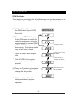
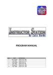
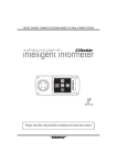
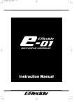
1
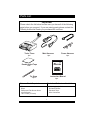
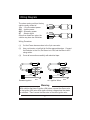
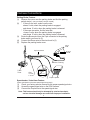
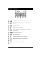
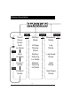
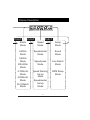
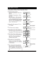
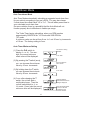
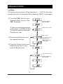
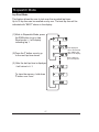
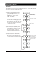
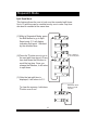
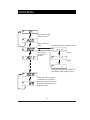
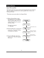
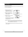
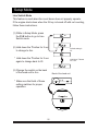
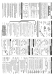
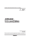
Instruction Manual
Parts List
Important
Please check the list below to make sure you have all of the following
parts before you proceed. If you are missing parts please contact the
GReddy Authorized Dealer you purchased the unit from.
Turbo Timer
Power Harness
Main Harness
1pc.
1pc.
1pc.
Double-sided Tape
Instruction Manual
1 set
Instruction Manual
Tie Strap
3 pcs.
1pc.
Minimum Tools Required
Tools for a Professional Installation
*
*
*
*
*
*
*
*
*
Pliers
Dikes
Phillips and Flat Screw drivers
10mm Wrench
Wire Tester (15V-min)
1
Soldering Iron & Solder
Drill and Drill Bits
Electrical Tape
Wire Connectors
Installation (using Optional Turbo Timer Harness)
(1)
(2)
(3)
Follow the key switch to it’s electrical connector, then unplug the
harness and place the Optional Turbo Timer harness in-line with the
key switch harness.
Connect the supplied power harness in between the 3-pin connector
of the optional harness and the 4-pin connector of the Turbo Timer.
Then connect the black wire with the loop connecter to a good
chassis ground.( to steel body)
key switch connector
Optional GReddy
Turbo Timer Harness
(sold separately)
key cylinder
3-pin connector
ground wire.
power harness
4-pin connector
parking / speed
harness
Turbo Timer
Important!
A bad ground connection can lead to a mechanical failure, therefore
please attach the ground to a non-painted surface of the vehicles
steel body.
2
Installation (without Optional Turbo Timer Harness)
(1)
(2)
(3)
(4)
Follow the key switch to it’s electrical connector, then unplug the
harness. Find the appropriate wires with either a factory service
manual or a volt meter. (see 2.3 for wiring)
Cut off the 3-pin connector on power harness. Then splice and solder
the appropriate wires to the power harness. (be sure to cover connections)
Then connect the black wire with the loop connecter to a good
chassis ground.( to steel body)
Reconnect the key switch harness.
key switch connector
splice and solder
the appropriate lines
ground wire.
power harness
key cylinder
4-pin connector
2-pin connector
parking / speed
harness
Turbo Timer
Important!
A bad ground connection can lead to a mechanical failure, therefore
please attach the ground to a non-painted surface of the vehicles
steel body.
3
Wiring Diagram
The wires coming out form the key
switch usually consist of:
12 v - 12 volt constant power
ON - Ignition power
ACC - Accessory power
ST - Starter signal
Other than these four wires, the
vehicle may have two ON wires.
12V
ACC
ON
ST
12V
ACC
ON
ON
ST
Wiring Procedure:
(1)
Cut the Power harness close to the 3-pin connector
(2)
Use a volt meter or test light to find the appropriate wires. Connect
the Red wire to the 12v, the Green to to ON, and the Blue to ACC
using solder.
(3)
Cover all connections carefully with electrical tape.
12V
ACC
12V
ACC
ON
ON
Red
Blue
ON
START
Red
Blue
Green
Black
START
Green
Black
Standard Ignition
w/ 2 Ignition Wires
Warning !
Warning
With vehicles that have 2 ignition (ON) wires, connect the Green wire
to the ignition (ON) wire which does not drop voltage when the starter
is activated. Then connect the Blue wire to the other ignition wire.
4
Harness Connections
Parking Brake Feature:
(1) Remove the cover over the parking brake and find the parking
switch wire(s). (see you factory service manual)
(2) * If there is one wire, make sure the wire:
shows 0 volts, when the parking brake is engaged.
and shows 12 volts, when the parking brake is released.
* If there are two wires, find the wire that:
shows 0 volts, when the parking brake is engaged.
and shows 12 volts, when the parking brake is released.
(3) Route the Brown wire from the 2-pin connector to the parking
brake switch you found in (2).
(4) Connect the Brown wire to the wire found in (2)
(5) Replace the parking brake cover.
0V
2-pin connector
12V
do not use
Brown / Parking
Turbo
Timer
Gray
not used
in the US
Shift lock
release uint
(for Japan only)
Purple / Speed
Speedometer / Auto timer Feature:
(Some vehicles do not have a speed signal to connect)
(1)
(2)
(3)
Check your factory service manual for the proper speed signal wire.
Access the speed signal wire on the ECU harness.
Connect the Purple wire to the speed signal wire.
Note: This feature should only be attempted by a trained mechanic,
serious electrical damage can result form improper installation.
5
Turbo Timer Functions
Back
OPTION Switch
Used to connect the
Remote Switching System (sold separately)
Line Switch
Display
TIME Button (Referred as "T")
Used when switching the main modes.
Used to change the countdown
time and set-up time.
SELECT Button (Referred as "S")
Used when switching the sub modes.
Used to start the stopwatch mode.
POWER Button (Referred as "P")
Turns the Turbo Timer "ON" or "OFF"
Used when switching the main and sub modes.
Shuts off engine and timer during count down.
6
Display Description
1
2
3
6
7
8
9
4
5
10
11
1
Attack Mode indicator. Flashes when Attack timer is activated.
2
Stopwatch Mode indicator. Flashes when the stopwatch is
activated.
3
Speed Mode indicator.
4
Displayed while in Battery Mode.
5
Best lap time indicator. Flashes the best lap time during
Stopwatch Mode.
6
Count Down Mode indicator.
7
Battery Mode indicator.
8
Auto Mode indicator in the Count Down Mode.
9
Displayed while in Attack mode or Speed Mode.
10
Displayed while in Stopwatch Mode.
11
Displayed with lap time while in Stopwatch mode.
7
Display Description
P+S+T
P+S+T
P+S+T
Stopwatch
Mode
Count
Down
Mode
Battery
Mode
Auto
Lo Mode
Voltage
Display
Mode
Lap
Mode
Auto
Hi Mode
Battery
Warning
Lo Mode
Lap Read
Mode
Preset 1
Mode
Battery
Warning
Hi Mode
Split
Mode
P+S
P+S
P+S
Split Read
Mode
Preset 2
Mode
8
Display Description
P+S+T
P+S+T
Attack
Mode
0-200m
Mode
0-400m
Mode
200-400m
Mode
0-100km/h
Mode
0-200km/h
Mode
50-100km/h
Mode
P+S+T
Speed
Mode
Setup
Mode
Speedometer
Mode
Sound
Mode
Speed peek
Mode
Line Switch
Mode
Speed Warning
Set up
Mode
RPM Setup
Mode
Speedometer
Set up
Mode
9
Operation Check
Parking Brake Safety Feature Operation Check
(1) Engage parking brake.
Manual Transmission: Place into
Neutral
Automatic Transmission: Place
into Park.
Start the engine. Make sure the
Turbo Timer powers up with the
music and display lights operating.
(note: The Turbo Timer may be turned
"Off" if so, press the "POWER" button
once to turn on the unit)
(2) Press P + S to select to "P-1" or
"P-2" Mode.
P+S
P+S
This shows P-1
selected.
After 2 sec. default
value will display.
(3) 1’00" will show in display.
Turn off the ignition
switch.
(4) First depress the brake pedal, so
that the car does not roll, then turn
the ignition "Off" with the key switch.
Count down begins.
(5) The Turbo Timer will then give a
warning "beep" and display "Sid"
Next the unit should begin the
counting-down mode.
(6) Reengage the Parking Brake.
Check to see if the "Sid" display
disappears and the unit continues
to count-down.
(7) Now release the Parking Brake.
the count down should stop and
"OFF" displayed. Then the Timer
and engine should immediately turn
off.
10
Pull the Parking brake.
During count down,
release the parking
brake.
Operation Check
Vehicle Speed Signal Safety Feature Operation Check
Warning !
Before moving your vehicle, be sure that the area around
your vehicle is clear. If not, you may cause an accident.
(1) Go over check procedure 4.3
"Parking Brake Feature Check"
before continuing.
Turn off the key
switch
(2) Carefully, place the vehicle into gear
and move the vehicle slowly.
Turbo Timer and engine should
then turn off.
During count down,
Place the car in gear
and move the vehicle.
This concludes the check
procedures.
Timer and engine
should trun off.
If the Turbo Timer did not power up, or these safety features
are not working, please recheck all the wiring connections
and then contact your Authorized GReddy Dealer.
11
Countdown Mode
Auto Countdown Mode
Auto Timer Mode automatically calculates a suggested count down time
for your vehicle, according to your car’s RPM. You may also choose
2 count down time offset ratios "Hi" or "Lo". This will add a preset time to
your calculated count down time.
On some vehicles, there is a possibility that the Auto Mode will not
function properly due to difference in usable rpm range.
The Turbo Timer begins calculating, when your RPM reaches
approximately 3000 RPM for "LO" mode and 2000 RPM for
"HI" mode.
A minimum value can be set from 0 sec. to 1 min 30 sec. by increments
of 10 sec. The factory setting is 0 sec.
Auto Timer Minimum Setting
This show -L- being
selected.
(1) Press the P+S switch to
display -L- or -H-. Two sec.
later, the current minimum
offset value will be displayed.
2 sec. later
(2) By pressing the T switch (once),
you can increase the minimum
value by 10 sec. increments
(3) By holding down the T switch,
you can increase the minimum
value by 30 sec. increments
Press T 3 times to
set to 30 sec.
2 sec. later
(4) 3 sec. after releasing the T
switch, the unit will alert a
confirmation beep. Then the
unit will switch back to -L- or
-H- mode. (2 sec. later the current
minimum value will be displayed.)
12
After the setting is
confirmed the minimum
setting is displayed
When the vehicle starts
to move, it will start
to add time to the
minimum set time.
Countdown Mode
Preset Mode
There are two Preset Countdown mode you can select from.
Preset mode can be set from 0 sec. to 9 min 59 sec. by increments
of 10 sec.
The factory setting is: 1 min. for P-1
3 min. for P-2
Preset Countdown Mode Setting
(1) Press the P+S button to
display P-1 or P-2. Two sec.
later, the current minimum
offset value will be displayed.
This show P-1 being
selected.
2 sec. later
(2) By pressing the T button (once),
you can increase the preset
value by 10 sec. increments
(3) By holding down the T button
you can increase the preset
value by 30 sec. increments
Press T button to
set to the desired
countdown time.
Ex. this show the time
set to 2 min.
(4) 3 sec. after releasing the T
button, the unit will alert a
confirmation beep. Then the
unit will switch back to P-1 or
P-2 mode.
After the setting is
confirmed the preset
time will be displayed.
13
Battery Mode
Battery Voltage Display Mode
This feature displays the "real-time" battery voltage.
There is a voltage warning feature that can be turned on and off.
The warning buzzer and the back light will flash when the voltage
exceeds the set voltage.
(1) To go to the Battery Mode from
Countdown Mode, press P+S+T
buttons and release S button first.
(2) V will display with the " real-time"
voltage.
14
"Real-time" battery
voltage will display.
Battery Mode
Voltage Warning Display Mode
When the Warning is set, the warning buzzer and the back light will
flash when the voltage exceeds the set voltage.
This feature will only work while in battery mode.
(1) Press the P+S button to
display -L- or -H-. Two sec.
later, the current minimum
offset value will be displayed.
At this time the back light will
turn red.
P-1 is selected here.
2 sec. later, the current
setting will display
(2) By pressing the T button (once),
you can increase the voltage
value by 0.1V increments.
Range for -L- setting is
10.0 ~ 12.0V
Range for -H- setting is
14.0 ~ 16.0V
(3) By holding down the T button
you can increase the voltage
value by 0.5V increments
By pressing T button,
set the desired voltage,
Ex. This show the
voltage set to 12.0 V
Minimum setting
will be the "off" position.
15
Stopwatch Mode
Lap Mode
This feature can record up to 30 lap times from 0 ~ 9’ 59" 99. Also while
recording the time, the best lap will be indicated by "BEST" on the display.
(1) Press the P+S+T button to go to
Stopwatch Mode. Two sec. later,
0’00" will display.
*if there are recorded time stored
in the memory, the 0’00" will flash.
To clear the memory, hold down
T button over 5 sec.
2 sec later, Standby
mode will display.
press S button to start.
press T button
(2) By pressing the S button once,
the stopwatch will start.
If the displayed time is
the best lap time,
"BEST" will show up
on the display.
(3) Press the T button to store and
display the lap time. To stop,
press the S button once.
press S button to stop
the last recorded lap
time will display.
16
Stopwatch Mode
Lap Read Mode
This feature allows the user to look over the recorded lap times.
Up to 30 lap time can be recalled one by one. The best lap time will be
indicated with "BEST" shown in the display.
(1)While in Stopwatch Mode, press
the P+S button to go to Lap
Read mode. L-1 will display
indicating lap 1.
If the displayed
time is the best lap
time, "BEST" will
flash on the display.
(2)Press the T button once to go
to the next lap time stored
Press T button to
go to next lap time.
(3) After the last lap time is displayed,
it will return to L-1.
To clear the memory, hold down
T button over 5 sec.
17
Stopwatch Mode
Split Mode
This feature can record up to 10 split times from 0 ~ 9’ 59" 99. Lap time
can also be recorded at the same time.
(1) While in the Stopwatch mode,
press the P+S button to go to
Split Mode. Two sec. later,
0’00" will display.
2 sec later, Standby
mode will display.
press S button to start.
*if there are recorded time stored
in the memory, the 0’00" will flash.
To clear the memory, hold down
T button over 5 sec.
press T button
(2) By pressing the S button once,
the stopwatch will start. At each
split point, press T button to
store and display the lap time.
(3) After the lap time, the display
will show the current count time.
To stop, press the S button once.
18
Press S button to stop.
Number of total split
time stored will display
followed by the total
time.
Stopwatch Mode
Split Read Mode
This feature allows the user to look over the recorded split times.
Up to 10 split time can be recalled one by one in order. Lap time
can also be recalled at the same time.
(1)While in Stopwatch Mode, press
the P+S button to go to Split
Read mode. P-1 will display
indicating Split point 1 followed
by the recorded time.
(2)Press the T button once to go to
the next split time stored. At any
time hold down the S button to
recall the lap time. Once you
release the S button, it will return
to split times.
Press T button to
go to next lap time.
(3) After the last split time is
displayed, it will return to P-1.
To clear the memory, hold down
T button over 5 sec.
19
Hold down the S
button to recall
lap time.
Attack Mode
0-200m, 0-400m, 200-400m, 0-100km/h, 0-200km/h, 50-1000km/h Mode
This feature allows the user to record 0-200m, 0-400m, 200-400m,
0-100km/h, 0-200km/h, 50-1000km/h times.
Important! - This feature should only be used on a race track where
it is safe. Please never try on the public highways.
*This feature requires the wiring of the vehicle speed sensor signal wire.
*To record 0-200km/h time, the vehicle must be equipped with speed
limiter cut device.
(1) Press P+S+T to go to main Attack Mode. In the attack mode, press
P+S button to go to one of the sub Attack Mode. 0’ 00" will display
indicating that the unit is in stand-by mode.
* When this feature is selected while the vehicle is moving, 0’ 00" will
flash indicating that the unit is not in stand-by mode. Always stop the
vehicle before selecting this feature.
* When the unit is in stand-by mode, press the T button to start the
count down start. This will not work for the 200-400m & 50-100km/h
mode.
* If there are data stored in the Attack Mode memory, --- will flash. To
clear the memory, hold down T button over 5 sec. or change to
different sub mode.
(2) The auto start timing is triggered by the vehicle speed sensor. The
timing will start as soon as the vehicle starts to move.
(3) The recorded time will be displayed until the mode is changed or
cleared.
* To restart the timing in the same mode, or to cancel the timing, hold
down T button over 5 sec. to clear. Then the unit will return to
stand-by mode.
20
Attack Mode
This shows 0-200m
Mode is selected
goes to stand-by
mode.
Countdown start by pressing T button
"Beep"
Auto Start by
Moving the
vehicle.
"Beep"
The timing will start with a "Beep" as
soon as the vehicle starts to move.
When the vehicle reaches
the distance or the speed
the mode is set to the timing
will stop automatically, and
display the time.
21
Speed Mode
Speedometer Mode
This feature allow the user to monitor the "real time" vehicle speed. With
use of the Speed Warning feature, buzzer and flashing back light will
warn the driver when the speed exceeds the set warning speed.
(1) Press the P+S+T button to go to
main Speed Mode.
The current speed
will display.
* Speedometer display range is
0 ~ 399km/h.
Speed Peek Mode
This feature will display the highest speed recorded while in Speed Mode.
(1)While in main Speed Mode,
press the P+S button to go to
Speed Peek Mode. -P- will
display followed by the current
peek speed.
The current peek
speed will display.
* To clear the memory, hold down
T button over 5 sec.
22
Speed Mode
Speed Warning Mode
This feature allow the user to set the warning speed to warn the driver
when the speed exceeds the set warning speed with a buzzer and
flashing back light.
*This feature only work while in the Speed Mode
(1)While in Speed Mode, press
the P+S button to go to Speed
Warning Setup mode. SET will
display followed by the current
warning setting.
* the warning range is:
0 ~ 399 km/h.
Press S button to set
up.
(2)Press the S button to change the
set position. Press the T button
to change the numbers.
Change the number
by pressing T button.
Press S button to
change the position.
(3) Press the S button when the
speed is set. This will complete
the set up.
23
Speed Mode
Speedometer Setup Mode
This feature allow the user to set the Turbo Timer speedometer to match
the vehicle’s speedometer.
(1)While in Speed Mode, press
the P+S button to go to
Speedometer Setup mode.
(2)Get the vehicle speed up to
40km/h. Press the T button
to set the speed.
After two cycles
(3) When the setup is complete,
40km/h will display.
Press T to set
* To clear the memory, hold down
T button over 5 sec. and repeat
the procedure above.
Important! - Make sure you perform this step with a passengers help.
Have the passenger operate the Turbo Timer while the
driver concentrate on driving safely.
* There is a possibility that the vehicle’s speedometer and the actual
vehicle speed.
24
Setup Mode
Sound Mode
This feature allow the user to turn the sound ON or OFF.
(1) While in Setup Mode, press
the P+S button to go to Setup
mode. Sud will display indicating
Sound Mode.
(2) Hold down the T button for 5 sec
to turn OFF.
* Hold down the T button for 5 sec
again to turn the sound back on.
25
2 sec later.
Hold down the T
button for 5 sec.
Setup Mode
Line Switch Mode
This feature is used when the count down does not properly operate.
If the engine shuts down when the IG key is turned off with out counting,
follow these instructions.
(1) While in Setup Mode, press
the P+S button to go to Line
Switch mode.
(2) Hold down the T button for 2 sec
to change to Acc.
Default setting is
IG.
* Hold down the T button for 2 sec
again to change back to IG
(3) Change the switch on the back
of the head unit to Acc.
Hold down T button
for 2 sec.
Back of the head unit
* Make sure that both of these
setting matches for proper
operation.
IG
26
Acc
Setup Mode
RPM Set Mode
This feature is used when the Auto Mode does not operate properly or to
set the Turbo Timer RPM to match the vehicle’s tachometer.
(1) While in Setup Mode, press
the P+S button to go to RPM
Set mode.
(2)The current RPM will display,
If the RPM does not match the
vehicle’s tachometer, bring the
engine speed to constant RPM
(2000 or 3000) and press S
button once. The number on the
very left will start to flash.
Current RPM will
display.
Press T button to set
the RPM
* After this step, let the engine
idle.
Press S button to
change set Position.
* Set the RPM to the engine
speed where the S button was
pressed.
(3)Press the T button to change the
numbers. Press the S button to
change the set position.
* Make sure that both of these
setting matches for proper
operation.
27
This show the unit
set to 3000 rpm