1
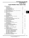
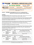
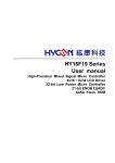
h a n g e Vi
e
w
N
y
bu
to
Bollettino Tecnico
Modelli
MOTOSLITTE 800 CFI
.d o
m
w
o
.c
lic
k
c u -tr a c k
C
m
20 dicembre
2010
o
.d o
w
w
w
w
w
C
lic
k
to
bu
y
N
O
W
!
XC
er
O
W
F-
w
PD
h a n g e Vi
e
!
XC
er
PD
F-
c u -tr a c k
Numero: 20/12/2010
Numeri di serie
TUTI I MODELLI 800 CFI
CORSO TECNICO MOTSLITTA 800CFI.
È DISPONIBILE UN CORSO TECNICO,IN LINGUA INGLESE, DEDICATO ALLE MOTOSLITTE CON
MOTORE 800 CFI DUE TEMPI.
QUESTA SPECIALE PUBBLICAZIONE È DEDICATA A CHI VOLESSE APPRENDERE FINO IN FONDO
IL FUNZIONAMENTO DELLA PROPRIA MOTOSLITTA ED AI CONCESSIONARI PER COMPLETARE LA
LORO FORMAZIONE TECNICA.
© Egimotors srl. Questa comunicazione è riservata ai Concessionari. Qualsiasi uso,in parte o completo, è espressamente vietato.
Pagina 1 di 1
.c
y
o
c u -tr a c k
.c
.d o
2008-2011 800 CFI Performance, Troubleshooting, and Diagnostic
Webcast & FAQs
Webcast Summary:
We are pleased to present a webcast of the recommended troubleshooting and diagnostic procedures
for 2008-2011 CFI Snowmobiles. The webcast will contain a presentation regarding troubleshooting and
diagnostics procedures we presented in the diagnostic booklet last year that was so well received.
Live Webcast Date: Wednesday, December 8, 2010 at 1:00 PM (central time zone)
Webcast Removal Date: 12/8/2011
Link to access the webcast:
http://www.stratosfour.com/programs/kp.cfm?A=97&B=4766&C=0
Webcast FAQs (FAQs will be listed within 2 weeks of initial broadcast)
Polaris Industries, Inc. | Webcast Series
Updated: 12/7/2010
m
o
w
w
w
.d o
C
lic
k
to
bu
y
bu
to
k
lic
C
w
w
w
N
O
W
!
h a n g e Vi
e
N
PD
!
XC
er
O
W
F-
w
m
h a n g e Vi
e
w
PD
XC
er
F-
c u -tr a c k
.c
h a n g e Vi
e
w
N
y
bu
to
k
CLEANFIRE™ FUEL INJECTION
Performance Diagnostics Guide
w
.d o
c u -tr a c k
o
.c
m
lic
c u -tr a c k
C
m
o
.d o
w
w
w
w
w
C
lic
k
to
bu
y
N
O
W
!
XC
er
O
W
F-
w
PD
h a n g e Vi
e
!
XC
er
PD
F-
.c
F-
h a n g e Vi
e
y
.c
Collect Customer and Service Information
The Service Advisor should collect accurate and relevant information
from the customer to assist the service technician with an accurate
diagnosis and successful repair.
Collect the following
• Customer and Machine Information
• Vehicle Identification Number verify VIN on the machine
• Miles and or hours as applicable on the machine
• Description of concern/fault in customers words
• Snow depth/conditions when fault occurred
• Ambient Temperature when fault occurred
• Operating Altitude when fault occurred
Page 2
.d o
m
o
m
o
c u -tr a c k
C
lic
k
to
bu
y
bu
to
k
C
lic
w
w
w
.d o
w
w
w
w
N
O
W
!
XC
N
CLEANFIRE™ Performance Diagnostic Guide
er
O
W
w
PD
h a n g e Vi
e
!
XC
er
PD
F-
c u -tr a c k
.c
F-
h a n g e Vi
e
y
.c
Collect Customer and Service Information (continued)
• Load carried on machine or being towed when fault occurs
• Frequency of fault occurrence intermittent or constant
• Warning lights or indicators illuminated (check engine, temperature,
detonation)
• Engine RPM when fault occurred
• Machine speed when fault occurred
• Engine temperature at which fault occurs
• Throttle opening at which fault occurs
• Type of fuel being used/fuel selector position
• Determine type of oil currently being used
Page 3
.d o
m
o
m
o
c u -tr a c k
C
lic
k
to
bu
y
bu
to
k
C
lic
w
w
w
.d o
w
w
w
w
N
O
W
!
XC
N
CLEANFIRE™ Performance Diagnostic Guide
er
O
W
w
PD
h a n g e Vi
e
!
XC
er
PD
F-
c u -tr a c k
.c
F-
h a n g e Vi
e
y
.c
Unit Inquiry
www.polarisdealers.com
Perform a Unit Inquiry on each machine to identify any applicable bulletins
or team tips that could assist with diagnostics
Step 1: Select
Unit Inquiry
under Service
and Warranty
Menu
Page 4
.d o
m
o
m
o
c u -tr a c k
C
lic
k
to
bu
y
bu
to
k
C
lic
w
w
w
.d o
w
w
w
w
N
O
W
!
XC
N
CLEANFIRE™ Performance Diagnostic Guide
er
O
W
w
PD
h a n g e Vi
e
!
XC
er
PD
F-
c u -tr a c k
.c
h a n g e Vi
e
y
.c
Unit Inquiry (continued)
Step 2: Input
VIN
Step 3: Select
“Find”
Page 5
.d o
m
o
m
o
c u -tr a c k
C
lic
k
to
bu
y
bu
to
k
C
lic
w
w
w
.d o
w
w
w
w
N
O
W
!
XC
N
O
W
F-
er
CLEANFIRE™ Performance Diagnostic Guide
w
PD
h a n g e Vi
e
!
XC
er
PD
F-
c u -tr a c k
.c
h a n g e Vi
e
y
.c
Unit Inquiry (continued)
• Verify consumer information
• Provides machine production date, purchase date,
and warranty status
Joseph
Customer
1212 Canyon Dr.
Step 4: Verify
Customer and
Unit
Information
800-555-1212
Smithville
WY
12121
Page 6
.d o
m
o
m
o
c u -tr a c k
C
lic
k
to
bu
y
bu
to
k
C
lic
w
w
w
.d o
w
w
w
w
N
O
W
!
XC
N
O
W
F-
er
CLEANFIRE™ Performance Diagnostic Guide
w
PD
h a n g e Vi
e
!
XC
er
PD
F-
c u -tr a c k
.c
F-
h a n g e Vi
e
y
.c
Unit Inquiry
• Bulletin and Team Tip information
• Bulletins or Teams Tips contain information or procedures which may
assist with diagnosis of machine
• Service Manual Chapters for specific model
• Warranty work history
Step 5: Bulletin
and Team Tip
Information
Page 7
.d o
m
o
m
o
c u -tr a c k
C
lic
k
to
bu
y
bu
to
k
C
lic
w
w
w
.d o
w
w
w
w
N
O
W
!
XC
N
CLEANFIRE™ Performance Diagnostic Guide
er
O
W
w
PD
h a n g e Vi
e
!
XC
er
PD
F-
c u -tr a c k
.c
h a n g e Vi
e
y
.c
Machine Maintenance History
• Obtain maintenance history
from customer
• Consult periodic maintenance
table in manual
• Lack of required maintenance
may be cause of performance
issue
2010-2011 Pro-Ride
Rush/Switchback/RMK
Service Manual
Page 8
.d o
m
o
m
o
c u -tr a c k
C
lic
k
to
bu
y
bu
to
k
C
lic
w
w
w
.d o
w
w
w
w
N
O
W
!
XC
N
O
W
F-
er
CLEANFIRE™ Performance Diagnostic Guide
w
PD
h a n g e Vi
e
!
XC
er
PD
F-
c u -tr a c k
.c
F-
h a n g e Vi
e
y
.c
Machine Maintenance History
(continued)
2010-2011 Pro-Ride
Rush/Switchback/RMK
Service Manual
Page 9
.d o
m
o
m
o
c u -tr a c k
C
lic
k
to
bu
y
bu
to
k
C
lic
w
w
w
.d o
w
w
w
w
N
O
W
!
XC
N
CLEANFIRE™ Performance Diagnostic Guide
er
O
W
w
PD
h a n g e Vi
e
!
XC
er
PD
F-
c u -tr a c k
.c
F-
h a n g e Vi
e
y
.c
Inspection with customer
Perform walk-around inspection of machine with customer
Note any of the following
• Mechanical or cosmetic damage
• Performance accessories installed (or recently removed)
• Modifications to chassis/suspension
Page 10
.d o
m
o
m
o
c u -tr a c k
C
lic
k
to
bu
y
bu
to
k
C
lic
w
w
w
.d o
w
w
w
w
N
O
W
!
XC
N
CLEANFIRE™ Performance Diagnostic Guide
er
O
W
w
PD
h a n g e Vi
e
!
XC
er
PD
F-
c u -tr a c k
.c
F-
h a n g e Vi
e
O
W
N
y
.c
Machine Modifications
Modifications including but not limited to the following
may cause severe engine damage and void the limited warranty
.d o
m
o
m
o
c u -tr a c k
C
lic
k
to
bu
y
bu
to
k
C
lic
w
w
w
.d o
w
w
w
w
!
XC
N
CLEANFIRE™ Performance Diagnostic Guide
er
O
W
w
PD
h a n g e Vi
e
!
XC
er
PD
F-
c u -tr a c k
.c
• Intake Systems Aftermarket/Modified (Airbox, Reeds)
• Turbocharger
• Nitrous Oxide Injection System
• Engine Modifications - Cylinder porting or altering compression (ask customer)
• Exhaust Components Aftermarket/Modified
• Clutching modification(except factory recommended for elevation recalibration)
• Track/Final Gearing changes
• Engine Controller/Fuel Controller Modules
• Not using Polaris VES Gold Plus Engine Oil
• Fuels other than commercial 87-93 octane oxygenated/non-oxygenated unleaded
Note: Installing aftermarket parts that reduce the effectiveness of the emission
system is a potential violation of the Clean Air Act. Tampering with emission
controls is prohibited by federal law
Page 11
F-
h a n g e Vi
e
y
.c
Service Inspection and Testing (Technician)
• Perform a walk-around inspection and note any damage or modification
on machine
• Verify customer concern with a test ride (if local conditions allow)
• Consult service manual and verify all required scheduled maintenance has
been performed
• Common maintenance items such as the drive belt, exhaust valves, fuel
filter, spark plugs, and type of fuel used can reduce performance level
• Verify type of fuel in tank and the fuel selector position
•Verify all applicable service or safety bulletins have been performed
(unit inquiry)
Page 12
.d o
m
o
m
o
c u -tr a c k
C
lic
k
to
bu
y
bu
to
k
C
lic
w
w
w
.d o
w
w
w
w
N
O
W
!
XC
N
CLEANFIRE™ Performance Diagnostic Guide
er
O
W
w
PD
h a n g e Vi
e
!
XC
er
PD
F-
c u -tr a c k
.c
F-
h a n g e Vi
e
y
.d o
m
o
m
o
.c
Digital Wrench Diagnostics
c u -tr a c k
C
lic
k
to
bu
y
bu
to
k
C
lic
w
w
w
.d o
w
w
w
w
N
O
W
!
XC
N
CLEANFIRE™ Performance Diagnostic Guide
er
O
W
w
PD
h a n g e Vi
e
!
XC
er
PD
F-
c u -tr a c k
.c
Utilize Digital Wrench to perform the following procedures
• Save a service report (include VIN) before starting any diagnostic procedures
• Verify most recent (up to date) version of Digital Wrench is installed
• Check for diagnostic trouble codes with Digital Wrench and utilize guided
diagnostics procedure
• Verify most recent flash file-set is installed and injector color matches map file-set
• Compare engine management sensor values to known good data from saved
service report(s)
Note: if sensor values are not correct verify connector/terminal/wiring integrity
All wire terminals
should be fully
seated and not
distorted
Page 13
F-
h a n g e Vi
e
y
.c
Clutch and Drive Belt Inspection and Service
• The PVT system transmits engine power to the track.
• Clutch components that are damaged, excessively worn, or misadjusted can
reduce performance
• Inspect belt for excessive wear, glazing, or cord pop-out
• Polaris recommends using the 3211115 belt with 800 CFI machines
• The 3211080 drive belt is narrower and has a 2 degree greater angle the
which will adversely change the belt-to-sheave clearance
• Inspect clutch/belt alignment, center-to-center, belt to sheave clearance
and driven clutch float
• Verify installed weights, springs and helix
are correct for application
• Inspect and clean clutch/crank taper
• Torque all clutch fasteners to specifications
Page 14
.d o
m
o
m
o
c u -tr a c k
C
lic
k
to
bu
y
bu
to
k
C
lic
w
w
w
.d o
w
w
w
w
N
O
W
!
XC
N
CLEANFIRE™ Performance Diagnostic Guide
er
O
W
w
PD
h a n g e Vi
e
!
XC
er
PD
F-
c u -tr a c k
.c
h a n g e Vi
e
y
.c
Clutch and Drive Belt Inspection and Service (continued)
Engine Mounts and Torque Stop
• Inspect engine mounts and torque stop clearance spec 0.010”-0.030”
(0.25mm-0.75mm)
• 2010 Front PTO side engine mount hardware can be installed on 2008-2009
800 CFI Models
Parts required to retrofit 2010 mount
(1) 1015891 – plate, nut, front
(1) 7518753 – bolt
(1) 5411685 – rubber mount top
(1) 5411686 – rubber mount bottom
(4) 7616637 – rivet
Front PTO side
engine mount
Page 15
.d o
m
o
m
o
c u -tr a c k
C
lic
k
to
bu
y
bu
to
k
C
lic
w
w
w
.d o
w
w
w
w
N
O
W
!
XC
N
O
W
F-
er
CLEANFIRE™ Performance Diagnostic Guide
w
PD
h a n g e Vi
e
!
XC
er
PD
F-
c u -tr a c k
.c
F-
h a n g e Vi
e
y
.c
Clutch and Drive Belt Inspection and Service (continued)
Inspect the following clutch components
• Drive clutch sheaves for grooves or cracking
• Weight pockets for wear
• Drive and driven clutch rollers (washer should be flush with roller)
• Bushings in moveable sheave, cover, helix, and weights
• Weights for grooves or ramp damage and verify they move freely on pins
• Spring for distortion or breakage and measure free length
• Drive clutch spring should be replaced periodically
Note: Thrust washers
not in alignment with
roller indicates excessive
roller bushing wear
Page 16
.d o
m
o
m
o
c u -tr a c k
C
lic
k
to
bu
y
bu
to
k
C
lic
w
w
w
.d o
w
w
w
w
N
O
W
!
XC
N
CLEANFIRE™ Performance Diagnostic Guide
er
O
W
w
PD
h a n g e Vi
e
!
XC
er
PD
F-
c u -tr a c k
.c
F-
h a n g e Vi
e
y
.d o
Fuel System
• Polaris recommends using the highest octane rating fuel available (91-93)
• Fuel should not be stored in metal containers
• Fuel used from storage containers should be poured through a screened funnel
• Period use of Polaris Carbon Clean Plus PN 2871326 is recommended
• Polaris Carbon Clean Plus is an excellent fuel stabilizer and removes unwanted
carbon deposits from engine components and exhaust valves
• Do not use fuel de-icer with ethanol blended fuel
c u -tr a c k
c u -tr a c k
o
m
o
.c
m
C
lic
k
to
bu
y
bu
to
k
C
lic
w
w
w
.d o
w
w
w
w
N
O
W
!
XC
N
CLEANFIRE™ Performance Diagnostic Guide
er
O
W
w
PD
h a n g e Vi
e
!
XC
er
PD
F-
.c
Polaris Carbon Clean
Plus PN 2871326
3
Page 17
3
h a n g e Vi
e
y
Fuel System (continued)
• Determine fuel ethanol content with volume test
• Oxygenated fuel contains alcohol or ether compounds
(Machines are calibrated for 91 Octane/Oxygenated)
.d o
o
m
o
.c
m
C
lic
k
to
bu
y
bu
to
k
lic
C
c u -tr a c k
w
w
w
.d o
w
w
w
w
N
O
W
!
XC
N
O
W
F-
er
CLEANFIRE™ Performance Diagnostic Guide
w
PD
h a n g e Vi
e
!
XC
er
PD
F-
c u -tr a c k
90%
Fuel
Sample
10%
water
10%
water
ethanol content test
Page 18
20%
Alcohol/
Water
mixture
10%
Alcohol
.c
h a n g e Vi
e
y
Fuel Octane (R+M/2)
Fuel Resistor
Wires
Non-oxygenated
91 or less
24 Ω
Un-plugged
Oxygenated (Up to 10%)
87/89/91+
24 Ω
Un-plugged
Non-oxygenated
91+
160 Ω
Plugged in
Factory Setting
Factory Installed
Page 19
.d o
o
w
m
C
m
o
.c
lic
k
to
bu
y
bu
to
k
lic
C
Fuel System (continued)
• Identify location of fuel selector wires/fuel resistor plug on machine
• If unsure of fuel Octane Rating or Oxygenated Compound content UNPLUG
the selector wire or install the 10% ethanol 24 ohm fuel resistor
c u -tr a c k
w
w
.d o
w
w
w
w
N
O
W
!
XC
N
O
W
F-
er
CLEANFIRE™ Performance Diagnostic Guide
w
PD
h a n g e Vi
e
!
XC
er
PD
F-
c u -tr a c k
.c
F-
h a n g e Vi
e
y
.c
PU-43506-A
Page 20
.d o
c u -tr a c k
m
m
w
o
c u -tr a c k
o
C
lic
k
to
bu
y
bu
to
k
lic
C
Fuel System
• Handle the fuel injectors with extreme care during service procedures
• Inspect condition of green injector isolators and o-rings prior to installation
• Thoroughly inspect the injector tip for damage
• Always replace a fuel injector that is damaged
•Verify fuel filter is not restricted (filter should be replaced initially at 1000 miles
and every 2000 miles thereafter)
• A restricted filter can reduce fuel flow to the injectors which may result in
serious engine damage
• Verify fuel pressure holds 58-60 psi at all RPM’s
(Note: fuel pressure should drop slowly when pump is not running)
w
w
.d o
w
w
w
w
N
O
W
!
XC
N
CLEANFIRE™ Performance Diagnostic Guide
er
O
W
w
PD
h a n g e Vi
e
!
XC
er
PD
F-
.c
F-
h a n g e Vi
e
y
.d o
o
m
o
w
m
C
lic
k
to
bu
y
bu
to
k
C
lic
.c
Ignition System
• Verify spark plug cap retention with audible click
• Verify spark plugs are correct for application
• Do not use spark plugs with a threaded top terminal
• Route and secure plug wires to reduce movement
•Run engine to full operating temperature to avoid plug fouling
c u -tr a c k
w
w
.d o
w
w
w
w
N
O
W
!
XC
N
CLEANFIRE™ Performance Diagnostic Guide
er
O
W
w
PD
h a n g e Vi
e
!
XC
er
PD
F-
c u -tr a c k
Note: Use only
solid terminal
spark plugs
2010-2011 Pro-Ride Rush/Switchback/RMK
Page 21
.c
F-
h a n g e Vi
e
y
.d o
m
o
m
o
.c
Ignition System (continued)
c u -tr a c k
C
lic
k
to
bu
y
bu
to
k
C
lic
w
w
w
.d o
w
w
w
w
N
O
W
!
XC
N
CLEANFIRE™ Performance Diagnostic Guide
er
O
W
w
PD
h a n g e Vi
e
!
XC
er
PD
F-
c u -tr a c k
.c
Severely worn spark plug cap. Note
Excessive wear on the spark plug terminal
damaged terminal and carbon/rubber from a loose plug cap. Replace spark plug
deposits. Replace spark plug and
and plug cap if this occurs
plug cap if this occurs
Page 22
F-
h a n g e Vi
e
y
.c
Exhaust System
• Verify integrity of exhaust temperature sensor wiring and terminals
• Apply anti-seize to exhaust temperature sensor threads
• Install single copper washer and torque exhaust temperature sensor to
specifications (32 ft.lbs. 44Nm consult service manual)
• When servicing exhaust do not remove temperature sensor from pipe
disconnect at connectors
Page 23
.d o
m
o
m
o
c u -tr a c k
C
lic
k
to
bu
y
bu
to
k
C
lic
w
w
w
.d o
w
w
w
w
N
O
W
!
XC
N
CLEANFIRE™ Performance Diagnostic Guide
er
O
W
w
PD
h a n g e Vi
e
!
XC
er
PD
F-
c u -tr a c k
.c
F-
h a n g e Vi
e
y
.c
Page 24
.d o
c u -tr a c k
m
m
w
o
c u -tr a c k
o
C
lic
k
to
bu
y
bu
to
k
lic
C
Exhaust System (continued)
• Verify function of exhaust temperature sensor with Digital Wrench run engine at
(3000 RPM/2Minutes)
• Perform exhaust temperature sensor resistance test (2.3MΩ at 392°F/76Ω at
1652°F) Note: Do not test with temp sensor at room temperature
w
w
.d o
w
w
w
w
N
O
W
!
XC
N
CLEANFIRE™ Performance Diagnostic Guide
er
O
W
w
PD
h a n g e Vi
e
!
XC
er
PD
F-
.c
F-
h a n g e Vi
e
y
.c
Exhaust System (continued)
• Inspect exhaust resonator for loose internal components
• Service variable exhaust system components and verify operation of exhaust
valves
• Always replace exhaust valve base gasket whenever removed
Page 25
.d o
m
o
m
o
c u -tr a c k
C
lic
k
to
bu
y
bu
to
k
C
lic
w
w
w
.d o
w
w
w
w
N
O
W
!
XC
N
CLEANFIRE™ Performance Diagnostic Guide
er
O
W
w
PD
h a n g e Vi
e
!
XC
er
PD
F-
c u -tr a c k
.c
F-
h a n g e Vi
e
y
.c
Page 26
.d o
m
w
o
m
o
c u -tr a c k
C
lic
k
to
bu
y
bu
to
k
lic
C
Engine Management System Throttle Position TPS Sensor
• Correct TPS voltage provides easy startup and maintains engine idle RPM
• Verify Throttle Position Sensor (TPS) voltage is within specifications
• Perform Throttle Position Sensor adjustment procedure outlined in service
manual or Digital Wrench
• Use Digital Wrench to set/display TPS voltage since it displays the actual ECU
values
• Verify warm engine idle RPM is within specifications 1700 +/-200 RPM
• Verify throttle plates are fully opened with throttle lever
w
w
.d o
w
w
w
w
N
O
W
!
XC
N
CLEANFIRE™ Performance Diagnostic Guide
er
O
W
w
PD
h a n g e Vi
e
!
XC
er
PD
F-
c u -tr a c k
.c
F-
h a n g e Vi
e
y
.c
Engine Management System TPS (continued)
• New machine with no previous TPS adjustment
• Verify TPS voltage with Digital Wrench
• Verify TPS voltage is within specifications
• If TPS voltage is within specification no further action is required
Page 27
.d o
m
o
m
o
c u -tr a c k
C
lic
k
to
bu
y
bu
to
k
C
lic
w
w
w
.d o
w
w
w
w
N
O
W
!
XC
N
CLEANFIRE™ Performance Diagnostic Guide
er
O
W
w
PD
h a n g e Vi
e
!
XC
er
PD
F-
c u -tr a c k
.c
F-
h a n g e Vi
e
y
o
m
o
.d o
m
C
lic
k
to
bu
y
bu
to
k
C
lic
.c
Engine Management System TPS (continued)
• TPS has not been previously adjusted
• Verify TPS voltage with Digital Wrench
• TPS voltage is outside of specification
• Adjust air screw to bring TPS voltage into specification
c u -tr a c k
w
w
w
.d o
w
w
w
w
N
O
W
!
XC
N
CLEANFIRE™ Performance Diagnostic Guide
er
O
W
w
PD
h a n g e Vi
e
!
XC
er
PD
F-
c u -tr a c k
Throttle Body Air
Screw Note:
Consult service
manual
Page 28
.c
F-
h a n g e Vi
e
O
W
N
y
.c
.d o
m
o
m
o
c u -tr a c k
C
lic
k
to
bu
y
bu
to
k
C
lic
w
w
w
.d o
w
w
w
w
!
XC
N
CLEANFIRE™ Performance Diagnostic Guide
er
O
W
w
PD
h a n g e Vi
e
!
XC
er
PD
F-
c u -tr a c k
.c
Engine Management System TPS (continued)
• TPS out of specifications and has been previously adjusted
• Perform TPS voltage adjustment procedure located in Digital Wrench Special
Tests Menu or service manual
• Perform TPS Base Setting Procedure
• Always perform TPS adjustment with Temperature Barometric Air Pressure TBAP
sensor connected
• Visually verify throttle plate synchronization
• Check throttle lever free play
• Check throttle lever and cable for binding by turning handlebars through
full range of motion
Page 29
F-
h a n g e Vi
e
O
W
N
y
.c
.d o
m
o
m
o
c u -tr a c k
C
lic
k
to
bu
y
bu
to
k
C
lic
w
w
w
.d o
w
w
w
w
!
XC
N
CLEANFIRE™ Performance Diagnostic Guide
er
O
W
w
PD
h a n g e Vi
e
!
XC
er
PD
F-
c u -tr a c k
.c
Engine Management System TPS (continued)
• TPS has been previously adjusted and throttle plates are out of synchronization
• TPS voltage adjustment procedure located in Digital Wrench Special Tests Menu
or service manual
• Perform TPS Base Setting Procedure before attempting synchronization
• Perform Full Setting Procedure if TPS voltage is outside of specifications and
the throttle plates are out of synchronization
• Always perform TPS adjustment with Temperature Barometric Air Pressure TBAP
sensor connected
• Visually verify throttle plate synchronization
• Check throttle lever free play
• Check throttle lever and cable for binding by turning handlebars through
full range of motion
Page 30
h a n g e Vi
e
y
.c
2007-2008 sealed two-piece
air box with air horn plate
2009-2010 sealed air box
Page 31
.d o
o
m
w
o
c u -tr a c k
m
C
lic
k
to
bu
y
bu
to
k
lic
C
Engine Management System
• A broken, modified, or improperly mounted air box may cause detonation,
backfiring and high-idle hang.
• The engine management system cannot compensate for air box flow changes
• Verify air box boot integrity
•Inspect air box/inlets for modifications or leaks
w
w
.d o
w
w
w
w
N
O
W
!
XC
N
O
W
F-
er
CLEANFIRE™ Performance Diagnostic Guide
w
PD
h a n g e Vi
e
!
XC
er
PD
F-
c u -tr a c k
.c
F-
h a n g e Vi
e
y
.c
.d o
m
o
m
o
c u -tr a c k
C
lic
k
to
bu
y
bu
to
k
C
lic
w
w
w
.d o
w
w
w
w
N
O
W
!
XC
N
CLEANFIRE™ Performance Diagnostic Guide
er
O
W
w
PD
h a n g e Vi
e
!
XC
er
PD
F-
c u -tr a c k
Engine Cooling System
• A correctly functioning cooling system maintains optimum engine temperature
•Thermostat begins to open at 115°F-125°F +/- 5°F (46°C-52°C)
•Do not operate machine without a thermostat
•Coolant bypasses the heat exchangers with thermostat closed to speed warm-up
•Engine operation above 175°F (80°C) the fuel and ignition timing adjusts to
protect engine
•Hot lamp illuminates to alert the operator when overheat condition occurs
•Operation with hot lamp flashing and engine misfiring can damage engine
•Educate customer on use of ice scratches (if equipped)
Page 32
.c
F-
h a n g e Vi
e
y
.c
•Perform engine compression test for extreme performance loss diagnosis
• Compression pressure will generally be 115-125psi on a broken in engine.
(800 CFI at sea level)
• Always hold throttle wide open and pull recoil rope rapidly five times.
•Inspect condition of piston skirts (note: sacrificial graphite coating)
•Pistons are anodized underneath the graphite composite coating
•Pistons are packaged with a molybdenum based lubricant on the wrist pin
bores and rings (do not remove lubricant)
800 CFI Pistons
Page 33
.d o
m
o
m
w
o
c u -tr a c k
C
lic
k
to
bu
y
bu
to
k
lic
C
Engine Mechanical
w
w
.d o
w
w
w
w
N
O
W
!
XC
N
CLEANFIRE™ Performance Diagnostic Guide
er
O
W
w
PD
h a n g e Vi
e
!
XC
er
PD
F-
c u -tr a c k
.c
h a n g e Vi
e
y
.d o
Material transfer
FIGURE A
Deep grooves
Flaking
FIGURE C:
FIGURE B:
Page 34
o
m
o
.c
Engine Mechanical (continued)
• Verify precision measurement tools are calibrated
• Verify torque wrench accuracy and calibration
• To avoid component distortion torque all engine fasteners to specifications
• Cylinder inspection and honing procedure
• Measure the bore 1/2" from the top of the cylinder in line with the piston pin
and 90° to the pin to determine if the bore is out of round
c u -tr a c k
m
C
lic
k
to
bu
y
bu
to
k
C
lic
w
w
w
.d o
w
w
w
w
N
O
W
!
XC
N
O
W
F-
er
CLEANFIRE™ Performance Diagnostic Guide
w
PD
h a n g e Vi
e
!
XC
er
PD
F-
c u -tr a c k
.c
F-
h a n g e Vi
e
y
.c
.d o
m
o
m
o
c u -tr a c k
C
lic
k
to
bu
y
bu
to
k
C
lic
w
w
w
.d o
w
w
w
w
N
O
W
!
XC
N
CLEANFIRE™ Performance Diagnostic Guide
er
O
W
w
PD
h a n g e Vi
e
!
XC
er
PD
F-
c u -tr a c k
Engine Mechanical (continued)
Cylinder inspection and measurement procedures
•Refer to service manual for engine specifications
• Measure 800 piston 24.5 mm up from bottom of skirt
• Measure installed ring gap ½” from top and bottom of cylinder (variation
• between gaps indicates taper)
• Measure cylinder to piston clearance (note: measurement location on pistons,
cylinder measuring techniques, and measurement tools)
• Follow engine break-in fuel/oil premix requirements (40:1 Polaris Blue
Semi-Synthetic)
24.5 mm
Page 35
.c
F-
h a n g e Vi
e
y
Page 36
.d o
m
w
o
o
.c
C
m
lic
k
to
bu
y
bu
to
k
lic
C
Polaris VES Gold Plus
• VES GOLD PLUS far exceeds the detergency, low
smoke, lubricity and port blocking requirements of
the JASO FD/ISO EGD 2 stroke oil classifications.
• Reduces deposit buildup on exhaust valves
• Pour Point- VES GOLD PLUS exhibits a pour point of
less than negative 60 degrees Celsius. This insures
superior and uniform oil delivery on cold start up a
well as superior pour-ability at very low temps
• Lubricity Index- VES GOLD PLUS exhibits superior
lubricating properties as opposed to the majority of
aftermarket oils
• Smoke- VES GOLD PLUS is formulated to be extremely
low smoke outperforming JASO criteria for low smoke
two stroke oils by 50%
• Cold Engine Starting/Pull effort reduction- VES GOLD
PLUS is formulated with super synthetic base stocks
that maintain good flow and exhibit no resistance to
movement at temperatures well below -40° F
c u -tr a c k
w
w
.d o
w
w
w
w
N
O
W
!
XC
N
CLEANFIRE™ Performance Diagnostic Guide
er
O
W
w
PD
h a n g e Vi
e
!
XC
er
PD
F-
c u -tr a c k
.c
F-
h a n g e Vi
e
y
Page 37
.d o
o
m
o
.c
Suspension and Chassis
•Inspect ski/track alignment
•Inspect suspension wheels, bearings and bushings for excess wear or binding
•Verify if factory/studded track is being used
•Verify factory recommended final gear ratio
•Inspect jackshaft and driveshaft bearings for excess wear or binding
•Verify brake caliper/pads are not dragging
c u -tr a c k
m
C
lic
k
to
bu
y
bu
to
k
C
lic
w
w
w
.d o
w
w
w
w
N
O
W
!
XC
N
CLEANFIRE™ Performance Diagnostic Guide
er
O
W
w
PD
h a n g e Vi
e
!
XC
er
PD
F-
c u -tr a c k
.c
F-
h a n g e Vi
e
y
.c
Summary:
• Machine setup and calibration
• Verify required scheduled maintenance has been performed
• Inspect for modifications that can reduce performance
• Gather accurate and complete information from the customer
• Utilize Polaris information resources including STOP, Unit Inquiry,
Team Tips, Service Manuals, and training materials
• Complete all available diagnostic procedures as outlined in service
manuals or Digital Wrench
• Consult a service manual for specifications, repair and diagnostic procedure
• After using all available resources and you require additional diagnostic
assistance use ASK Polaris to contact technical service
Page 38
.d o
m
o
m
o
c u -tr a c k
C
lic
k
to
bu
y
bu
to
k
C
lic
w
w
w
.d o
w
w
w
w
N
O
W
!
XC
N
CLEANFIRE™ Performance Diagnostic Guide
er
O
W
w
PD
h a n g e Vi
e
!
XC
er
PD
F-
c u -tr a c k
.c