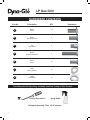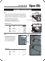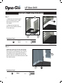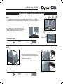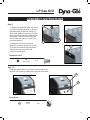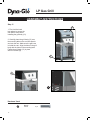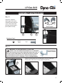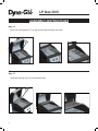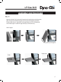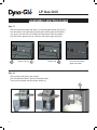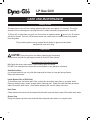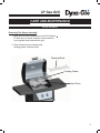
1
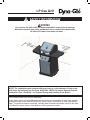
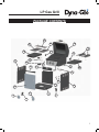
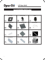
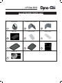
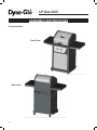
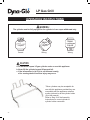
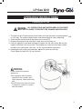
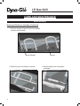
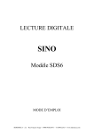
LP Gas Grill Model # DGP350NP/DGP350NP-D USER’S MANUAL AND OPERATING INSTRUCTIONS ANS Z21.58a – CSA 1.6a-2008 Outdoor Cooking Gas Appliance Assembler/Installer: This manual contains important information necessary for the proper assembly and safe use of this appliance. Read and follow all warnings and instructions before assembling and using this appliance. Leave these instructions with the consumer. Consumer/User: Follow all warnings and instructions when using this appliance. Retain these instructions for future reference. DANGER: If you smell gas: 1. Shut off gas to the appliance. 3. Open Lid. 4. If odor continues, keep away from the appliance and immediately call your WARNING: 1. Do not store or use gasoline or other of this or any other appliance. 2. An LP cylinder not connected for use shall not be stored in the vicinity of this or any other appliance. 3. This grill is for outdoor use only, and shall not be used in a building, garage, under overhangs or any other enclosed area. 4. Do not leave a lit grill unattended. Keep children and pets away from the grill at all times. Questions, problems, missing parts? Before returning to your retailer, call our customer service department at 1-877-447-4768 8:30 a.m. – 4:30 p.m. CST, Monday – Friday or email us at [email protected] 70-10-001 REV: 002-01-25-11 LP Gas Grill STOP! NO NEED TO RETURN TO THE STORE Questions With The Assembly? Require Parts Information? Product Under Manufacturers Warranty? Call Toll Free : 1-877-447-4768 8:30 a.m. – 4:30 pm CST, Monday – Friday Retain This Owner’s Manual And Proof Of Purchase For Future Reference To help us help you Fill in the information below: Date of Purchase Place of Purchase Model Number Product Serial No. MODEL NUMBER AND PRODUCT SERIAL NUMBER CAN BE FOUND ON THE RATING LABEL OF YOUR GRILL. LP Gas Grill TABLE OF CONTENTS Safety Information .............................................................................................. 2 - 3 Package Contents ............................................................................................. 4 - 5 Illustrated Parts List .......................................................................................... 6 - 7 Hardware Contents .................................................................................................... 8 Preparation ................................................................................................................. 8 Assembly Instructions ......................................................................................... 9 - 20 Operation Instructions ........................................................................................ 21 - 25 Care and Maintenance ........................................................................................ 26 - 30 Troubleshooting ............................................................................................................ . 31 Replacements Parts List .................................................................................... 32 - 33 Warranty ...................................................................................................................... 34 1 LP Gas Grill SAFETY INFORMATION Please read and understand this entire manual before attempting to assemble, operate or install the product. If you have any questions regarding the product, please call customer service at 1-877-447-4768, 8:30 a.m. – 4:30 pm CST, Monday – Friday 1. DO NOT store or use gasoline or any other flammable vapors and liquids within 25 feet (8 m) of this or any other appliance. 2. An LP Cylinder not connected for use should be stored a minimum of 10 feet (3 m) away from this or any other appliance. 3. This grill is for use with propane gas only (propane gas cylinder not included). 4. Never attempt to attach this grill to the self-contained propane system of a boat, camper trailer, motor home or house. 5. Never use charcoal or lighter fluid with the grill. 6. Do not use gasoline, kerosene or alcohol for lighting. The LP gas supply cylinder used with this appliance must be: (a) Constructed and marked in accordance with the Specifications for LP-Gas Cylinders of the U.S. Department of Transportation (D.O.T.) or the National Standard of Canada, CAN/CSA-B339, Cylinders, Spheres and Tubes for Transportation of Dangerous Goods; and Commission, as applicable; and (b) Provided with a listed overfilling prevention device. (c) Provided with a cylinder connection device compatible with the connector for outdoor cooking appliances. This grill is not intended to be used in or installed on recreational vehicles and/or boats. 7. Do not attempt to move the grill while it is lit or when it is hot. The casters should be locked when not moving the grill. 8. Do not use the grill unless it is completely assembled and all parts are securely fastened and tightened. 9. Keep all combustible items and surfaces at least 36 inches (91.44 cm) away from the grill at all times. 10. Do not use in an explosive atmosphere. Keep grill area clear and free from combustible materials, gasoline and other flammable vapors and liquids. 11. Do not touch metal parts of grill until it has completely cooled (about 45 minutes) to avoid burns, unless you are wearing protective gear (pot holders, gloves, BBQ mittens, etc…). 12. Do not alter this grill in any manner. 13. Clean and inspect the hose before each use. If there is evidence of abrasion, wear, cuts, or leaks, the hose must be replaced prior to operating the appliance. The replacement hose assembly will be that which is specified by GHP Group, listed in the repair parts list in this manual. 14. Move gas hoses as far away as possible from hot surfaces and dripping hot grease. 15. Never keep a filled container in a hot car or car trunk. Heat will cause the gas pressure to increase, which may open the relief valve and allow gas to escape. 16. Keep the grill’s valve compartment, burners and circulating air passages clean. Inspect the grill before each use. Do not obstruct the flow of gas or ventilation air. 17. The use of alcohol, prescription or non-prescription drugs may impair the operator’s ability to properly assemble or safely operate the grill. 18. Always open grill lid slowly and carefully as heat and steam trapped within the grill can burn you severely. 19. Do not leave a lit grill unattended. Keep children and pets away from the grill at all times. 20. Do not place this grill on any type of tabletop surface. The grill should be placed on a flat and level surface. 21. Do not use the grill in high winds. 2 LP Gas Grill SAFETY INFORMATION WARNING Do not place the grill under overhead combustible construction or awnings. Minimum clearance from sides and back of unit to combustible construction, 36 inches (914.4mm) from sides and back. 36 in. (914.4 mm ) . 36 in 14.4mm) (9 NOTE: The installation must conform with local codes or, in the absence of local codes, with either the National Fuel Gas Code, ANSI Z223.1/NFPA 54, Natural Gas and Propane Installation Code, CSA B149.1, or Propane Storage and Handling Code, B149.2. CALIFORNIA PROPOSITION 65 WARNING: Fuels used in gas or oil fired appliances and the products of combustion of such fuels, contain chemicals known to the State of California to cause cancer, birth defects or other reproductive harm. This product contains chemicals, including lead and lead compounds, known to the state of California to cause cancer, birth defects or other reproductive harm. 3 LP Gas Grill PACKAGE CONTENTS BEFORE STARTING ASSEMBLY, UNPACK CARTON AND VERIFY CONTENTS. COMPARE ENCLOSED PARTS WITH PACKAGE CONTENTS LIST AND DIAGRAM. IF ANY PART IS MISSING OR DAMAGED, DO NOT ATTEMPT TO ASSEMBLE THE PRODUCT. CONTACT CUSTOMER SERVICE FOR REPLACEMENT PARTS. 1-877-447-4768 8:30 a.m. – 4:30 pm CST, Monday – Friday. 4 Part No. Description Qty Part No. Description Qty 11 Bottom Shelf 1 12 12 Grill Body 1 22 Locking Caster 2 13 13 Control Knob 2 33 Caster 2 14 14 Collapsible Shelf Support A 2 44 Cart Left Side Panel 1 15 15 Collapsible Shelf Support B 2 55 Cart Right Side Panel 1 16 16 Heat Tent 2 66 Cylinder Holder 1 17 17 Cooking Grate 2 77 Pin 2 18 18 Warming Rack 1 88 Cart Rear Panel 1 19 19 Left Shelf 1 99 Upper Front Door Brace 1 20 20 Right Shelf 1 10 10 Door Assembly 1 21 21 Grease Cup Clip 1 11 11 Upper Swivel Rear Panel 1 22 22 Grease Cup 1 LP Gas Grill PACKAGE CONTENTS 18 12 17 17 16 19 14 15 21 4 22 13 13 11 9 20 6 7 8 10 3 3 2 1 5 2 5 LP Gas Grill ILLUSTRATED PARTS LIST Bottom Shelf Locking Caster Caster 1 2 Cart Left Side Panel 3 Cart Right Side Panel Cylinder Holder 3 5 Pin 6 Cart Rear Panel Down Upper Door Brace 7 8 Door Assembly 9 Cart Swivel Rear Panel Upper Grill Body 10 6 11 12 LP Gas Grill ILLUSTRATED PARTS LIST Control Knob Collapsible Shelf Support A 13 Collapsible Shelf Support B 14 Heat Tent 15 Cooking Grate Warming Rack 16 17 18 Left Shelf Right Shelf Grease Cup Clip 19 20 21 Grease Cup 22 7 LP Gas Grill HARDWARE CONTENTS Part No. Description QTY A M6x12 Scr ew 30 B M4x10 Flat Head Screw 4 C M6 Step Screw 4 D M6x25 Round Head Screw 4 E M5x12 Scr ew 16 Illustration F 6MM Spring Washer 16 G 6MM Flat Washer 16 Tools Required for Unpacking, Assembly and Leak Testing of This Product: Phillips Screwdriver Spray Bottle Estimated Assembly Time: 30-45 minutes 8 LP Gas Grill ASSEMBLY INSTRUCTIONS 3 Step 1 1. Secure each locking caster (2) to the back side (side that is beveled for access to locking mechanism when assembled and upright) of the bottom shelf (1) using four screws (A) four spring washers (F) ) and four flat washers (G). Then tighten all screws. 2. Install the casters (3) to the front side (not beveled) of bottom shelf using four screws (A) four spring washers (F) ) and four flat washers (G). Then tighten all screws. 1 Back Side Beveled Hardware Used A F 6MM Spring Washer 16 pc G 6MM Flat Washer 16 pc Step 2 First, remove the pins (7) from the cylinder holder (6). Insert the cylinder holder (6) through the holes in the bracket pre-attached to the cart right side panel (5). Lock in place with the pins (7). A F M6x12 Scr ew 2 16 pc G 5 7 6 5 7 Parts Used 6 Cylinder Holder 6 1 pc 7 Pin 2 pc 9 LP Gas Grill ASSEMBLY INSTRUCTIONS Step 3 4 1. Attach the cart left side panel (4) to the bottom shelf (1) with two screws (A), but do not fully tighten. A 2. Attach the cart right side panel (5) to the bottom shelf (1) in the same way. 4 A 1 5 Hardware Used M6x12 Scr ew A 1 4 pc A: M6x12 Screw Qty: 4pcs 5 Step 4 Install two screws (A) into the cart left side panel and two screws (A) into the cart right side panel (5) as illustrated at right. Do not fully tighten screws (keep approximately 4 to 6mm from fully installed) as the cart rear panel (8) has key hole slots that need to slide onto these screws. 8 5 Hardware Used A 10 M6x12 Scr ew 4 pc A LP Gas Grill ASSEMBLY INSTRUCTIONS 4 Step 5 1. Align the key holes in the cart rear panel (8) with the 4 screws just installed into the cart left and right side panels. Push cart rear panel (8) onto screws and down to meet bottom shelf (1). 2. Secure the cart rear panel (8) to the bottom shelf (1) with two screws (A). Next, tighten the 4 screws on the cart left and right side panels (4 and 5). 8 5 1 A Tighten Screw (A). Hardware Used M6x12 Scr ew A 2 pc Step 6 5 Secure the upper door brace (9) to the cart left and right side panels using four screws (A), and then tighten the screws. A 9 5 4 A: M6x12 Scr Qty: 4pcs A Hardware Used A M6x12 Scr ew 4 9 4 pc 11 LP Gas Grill ASSEMBLY INSTRUCTIONS Step 7 Install the door assembly (10) to the cart left side panel (4) with four flat head screws (B) and tighten. 4 B 10 Hardware Used B M4x10 Scr ew 4 pc Step 8 FULLY TIGHTEN ALL SCREWS AT THIS TIME. 10 NOTE: When not in use put the match holder into the hole of door inner as shown below. 4 B 12 LP Gas Grill ASSEMBLY INSTRUCTIONS Step 9 1. Secure the cart swivel upper rear panel (11) to the cart left side panel (4) and cart right side panel (5) with two screws (C). Then install another 2 screws (C) into the upper mounting holes of the left and right side panels. These will secure the cart swivel upper rear panel (11) when it is in the closed position. 2. Rotate the cart swivel rear panel upper (11) upwards until the two screws (C) on the cart left and right side panels snap into the two slots on the cart swivel rear panel upper. 5 C 4 11 11 Hardware Used M6 Step Screw C 4 pc Step 10 Install the control knobs (13) onto the control panel of the grill body (12) by gently pushing them onto the valve stem. 12 13 Parts Used 13 Control Knob 2 pc 13 LP Gas Grill ASSEMBLY INSTRUCTIONS Step 11 1. First, lock the back two casters to ensure the cart doesn’t move while installing the grill body (12). 2. Carefully place the grill body (12) over the mounting tabs on the cart side panels and onto the cart. Make sure the gas hose is inside the cart. Align the holes in the grill body with the holes in the mounting tabs. Fasten the grill body (12) in place with four screws (D). 2 12 D Hardware Used D 14 M6x25 Scr ew 4 pc 12 LP Gas Grill ASSEMBLY INSTRUCTIONS Step 12 Install the collapsible shelf support A (14) and collapsible shelf support B (15) on both sides of the grill body using hardware part E (M5x12 screw). A 14 B 15 15: Collapsible Collapsible Shelf Support B Shelf Support Qty: 2 pcs 14 15 E 12 Hardware Used E M5x12 Scr ew 16 pc Step 13 WARNING: IT IS VERY IMPORTANT TO CHECK AND ENSURE THAT EACH AND EVERY BURNER IS FULLY ENGAGED WITH THE ADjACENT VALVE ORIFICE BEFORE COMPLETING STEP 13. FAILURE TO DO SO MAY RESULT IN FIRE OR ExPLOSION, POSSIBLY CAUSING SERIOUS INjURY OR DEATH. REFER TO MAINTENANCE SECTION INSTRUCTIONS TO PROPERLY CHECK THE ENGAGEMENT. Open the lid and place the two heat tents (16) on the brackets directly above the burners on the inside the grill body. 16 15 LP Gas Grill ASSEMBLY INSTRUCTIONS Step 14 Place two cooking grates (17) on the grill body brace and grill rear panel. 17 Step 15 Install the warming rack (18) as illustrated below. 16 18 LP Gas Grill ASSEMBLY INSTRUCTIONS Step 16 Align the left shelf (19) to the shelf support and insert between shelf supports, then swing the left shelf 90 degrees up and push shelf against grill body. Finally, press down on side shelf close to grill body until it is fully fastened to the shelf support. Install the right shelf (20) in the same way. Shelf Support Swing shelf up 90 degrees Press down Push 17 LP Gas Grill ASSEMBLY INSTRUCTIONS Step 17 Open the cart swivel upper rear panel (11) and hang the grease cup clip (21) onto the bottom of the grill body by pushing the small top part of the grease cup clip (21) into the hole in the bottom of the grill body. Place the grease cup (22) into the grease cup clip. Close the cart swivel upper rear panel. 11 Grease cup clip Grease cup 22 21 Close the cart swivel upper rear panel. Step 18 Open the door and place a gas cylinder (not included) filled with LP gas into the bottom shelf. Then lock the cylinder with the cylinder holder (6). 6 18 LP Gas Grill ASSEMBLY INSTRUCTIONS CHECKING FOR LEAKS After all connections are made, check all connections and fittings on the LP gas tank valve, gas hose and regulator for leaks with a water and soap solution. To prevent fire or explosion while testing for a leak: Always perform leak test prior to lighting the grill. Do not smoke while testing for a leak. Always perform leak tests outdoors in a well ventilated area. Do not use any source of flame while testing for leaks. Do not use the grill until any and all leaks are corrected. If you are unable to correct a leak, disconnect the propane supply and call a gas appliance service dealer. PERFORM LEAK TEST Prepare leak test solution by combining 1 part liquid dish soap with 3 parts water. Total solution required is approximately 2-3 oz. (70-90ml.). Put leak test solution in a spray bottle. Ensure all control knobs are in the ‘OFF’ position. Open LP gas tank valve. Spray leak test solution on all gas carrying connections and fittings. Presence of bubbles at areas of applied test solution indicates a gas leak. If leaks are detected or you smell or hear gas, shut off the LP gas tank immediately and repair or replace the defective part. Do not use the grill until all leaks are corrected. 19 LP Gas Grill ASSEMBLY INSTRUCTIONS Fully Assembled Front View Rear View 20 LP Gas Grill OPERATION INSTRUCTIONS CAUTION : Only use the regulator and hose assembly provided! If a replacement is necessary, please call our customer service center. Do not use replacement parts that are not intended for this grill. Connecting Gas Cylinder: The propane gas supply cylinder to be used must be constructed and marked in accordance with the Specifications for LP Gas Cylinders of the U.S. Department of Transportation (D.O.T.) or the National Standard of Canada, CAN/CSA-B339, Cylinders, Spheres and Tubes for Transportation of Dangerous Goods; and Commission, as applicable; and Provided with a listed overfilling prevention device. Use only 20-pound cylinders (Height 18.11”, Diameter Tank 9.84”, Diameter foot: 8.03”) equipped with a cylinder connection device compatible with the connection for outdoor cooking appliances. The cylinder must include a collar to protect the cylinder valve. The gas cylinder should not be dropped or handled roughly! If the appliance is not in use, the gas cylinder must be disconnected. Storage of an appliance indoors is permissible ONLY if the cylinder is disconnected and removed from the appliance. Cylinders must be stored outdoors out of the reach of children and must not be stored in a building, garage or any other enclosed area. Your cylinder must never be stored where temperatures can reach over 125°F. Place dust cap on cylinder valve outlet whenever the cylinder is not in use. Only install the type of dust cap on the cylinder valve outlet that is provided with the cylinder valve. Other types of caps or plugs may result in leakage of propane. Before connection, be sure that there is no debris caught in the outlet of the gas cylinder, outlet of the regulator valve or in the outlet of the burner and burner ports. Connect regulator valve and hand-tighten firmly. Disconnect the propane cylinder from the regulator valve when the grill is not in use. DO NOT obstruct the flow of combustion air and ventilation air to the grill. The propane cylinder must be arranged for vapor withdrawal and equipped with a listed overfilling prevention device. Please put the proper cylinder orientation to provide vapor withdrawal. 21 LP Gas Grill OPERATION INSTRUCTIONS WARNING : The cylinder must be fully upright for the cylinder to have vapor withdrawal only. Vapor Vapor Vapor Liquid Liquid Liquid Correct Wrong Wrong CAUTION a. Do not store a spare LP-gas cylinder under or near this appliance. b. Never fill the cylinder beyond 80 percent full. c. If the information in (a) & (b) is not followed exactly, a fire causing death or serious injury may occur. 6 22 *Other cylinders may be acceptable for use with this appliance provided they are compatible with the appliance retention means (referred to as the cylinder holder (6) in this manual). Refer to Step 18 of the Assembly Instructions for correct cylinder to cylinder holder connection. LP Gas Grill OPERATION INSTRUCTIONS Connecting the LP Tank WARNING : ALL INSTRUCTIONS AND SAFEGUARDS ON THIS PAGE MUST BE FOLLOWED TO PREVENT FIRE, DAMAGE AND/OR INjURY. 1. The knob on the LP tank must be closed. Make sure that the knob is turned clockwise to a full stop. The cylinder supply system must be arranged for vapor withdrawal. 2. Check that the control knob on the control unit is turned off. 3. Remove the protective cap from the LP tank valve and coupling nut. 4. Hold the regulator in one hand and insert the nipple into the valve outlet. Be sure the nipple is centered in the valve outlet. The coupling nut connects to the large outside threads on the valve outlet. Use care – do not cross thread the connection. 5. Hand-tighten the coupling nut clockwise until it comes to a full stop. Firmly tighten by hand only. Do not use tools. Straight WARNING In the connection process, make sure: the regulator inlet connector mates with the cylinder valve outlet properly, safely and firmly, and; the LP-Gas hose does not come in contact or remain in contact with the firebox. 23 LP Gas Grill OPERATION INSTRUCTIONS Lighting The Grill Before first use Remove all hangings or plastic straps, if present. Before you cook on your new gas grill, it is important to clean your grill with heat. To do this, operate the grill for approximately 15 minutes with the lid closed and the control knob in the highest position. This will clean the internal parts by burning off any residue and odor from the manufacturing process. CAUTION: If the flame extinguishes accidentally during ignition or operation, immediately TURN OFF the cylinder valve and then TURN OFF the control knob. LIGHTING INSTRUCTIONS Warning: Do not lean over grill when lighting. Read instructions before lighting. 1. Check that the control knobs are in the off position. 2. Open valve at tank fully by turning counterclockwise. 3. Open lid during lighting. 4. Depress and turn control knob counterclockwise from off position, past the ignite position, to the high position. You may need to repeat several times to ignite the burner. If ignition does not occur in 5 seconds, turn the control(s) off, wait 5 minutes, and repeat the lighting procedure. If the burner still does not light, check that there is gas in the cylinder and follow the match lighting instructions. 24 LP Gas Grill OPERATION INSTRUCTIONS LIGHTING THE GRILL WITH A MATCH Warning: Do not lean over grill when lighting. Read instructions before lighting. 1. Insert a match in the end of the match holder that is installed on the inside of the cabinet door. 2. Light the match. 3. Immediately place the lit match through the 20mm hole on the side of the grill body, nearest the burner you want to light. Make sure the lit match is close to the burner ports. 4. Press in the control knob that operates that burner and rotate counterclockwise to High position and burner should light immediately. 5. Adjust burners to desired cooking settings. If lighting both burners is required, repeat steps 1 through 4 to light the other burner. SHUTDOWN INSTRUCTIONS 1. Turn control knobs clockwise to the off position. 2. Close valve at tank fully by turning clockwise. 3. Close lid. Turn off LP supply at cylinder when appliance is not in use. 25 LP Gas Grill CARE AND MAINTENANCE Cooking Grates The best time to ‘burn-off’ the cooking grates is after every use (approx. 15 minutes). The grill is already hot from cooking thus requiring less fuel to obtain necessary temperature for ‘burn-off’. To “Burn Off” or heat clean your grill, turn the burners to highest position and run for 15 minutes with the lid closed. Then turn off the burners and use a wire brush to clean excess food residue from the grates. The porcelain grates have an enamel finish (similar to glass) and should be handled with care not to chip. Other Parts CAUTION: Ensure the grill is cool before cleaning and conducting maintenance and with the gas supply turned off at the LP-Gas cylinder. Recommended Cleaning Supplies Mild liquid dish soap, warm water, nylon cleaning pad, wire brush DO NOT use cleaners that contain acid, mineral spirits or any abrasive substance. Outside Surfaces It is recommended to use only mild dish soap and hot water to clean grill and grill parts. Rinse with warm water. Inside Bottom Pan of Grill Body To avoid flare-ups, the bottom pan of the cooking box should be kept clean on a regular basis. Remove residue using a brush, scraper and/or cleaning pad. Wash with mild dish soap and warm water. Rinse with warm water. Avoid water splashing into venture tubes of burners. Heat Tents Clean residue with wire brush and wash with mild dish soap and warm water. Rinse with warm water. Grease Cup Empty the grease cup and clean with mild dish soap and warm water on a regular basis. 26 LP Gas Grill CARE AND MAINTENANCE Burner Assembly Removing The Burner Assembly 1. Make sure all control knobs are in the OFF position, LP tank valve is closed, and tank is disconnected from regulator and removed from grill. 2. Open lid and remove warming rack, cooking grates, and heat tents. Warming Rack Cooking Grates Heat Tents 27 LP Gas Grill CARE AND MAINTENANCE Burner Assembly Removing The Burner Assembly (Continued) 3. Remove screws at back of burners to detach burners from brackets. Burner Bracket 4. Slide burners out of firebox as shown. 28 Burner 5. Detach ignition wire from ignitor as shown. LP Gas Grill CARE AND MAINTENANCE Burner Assembly Cleaning the Burner Assembly – Make sure the grill is cool 1. Turn gas off at the control knobs and propane tank. 2. Disconnect LP-Gas cylinder from hose and regulator. 3. Remove warming rack, cooking grates and heat tents. 4. Detach burner by removing the screws at the back of the burners to detach them from the brackets. 5. Detach ignition wire from electrode by hand only. DO NOT use pliers or any other tool as it may damage the electrode or wire. 6. Lift burner slowly. 7. Ensure all burner ports are clear of clogs. Use of a pin or paper clip works well. 8. Ensure burner is free of any damage. If damage is found, replace with new burner. 9. Ensure the end of the burner and primary air screen are clear from insect nests, dirt or debris. Re-installing the Burner Ensure that gas valve orifices are correctly positioned inside burner inlet (venturi). The use of a flashlight may be necessary to ensure the correct position. It is recommended to view the correct position through the firebox vent holes as illustrated below. WARNING: If the instructions above are not followed, a fire or explosion may result, possibly causing serious bodily injury or death. 29 LP Gas Grill CARE AND MAINTENANCE Checking The Flame For maximum fuel efficiency and cooking performance, flame should be a blue-yellow color and be between 1- 2 inches high. To check the flame, view the flame through the match lighting hole in the side of the firebox. Yellow Yellow Light Blue 2” Light Blue Blue Blue Good Flame Bad Flame Other Care and Maintenance It is recommended that inspection and service on this appliance be conducted annually by a qualified service person. It is recommended that you regularly check that the outdoor cooking appliance area is clear and free from combustible material, gasoline and other flammable vapors and liquids. It is recommended that you regularly check that the flow of combustion and ventilation air is not obstructed. It is recommended that you regularly check that the ventilation openings of the cylinder enclosure (cabinet) are free and clear from debris. It is recommended that you regularly check and clean the burner/venturi tubes for insects and insect nests. A clogged tube can lead to a fire beneath the grill. 30 LP Gas Grill TROUBLESHOOTING PROBLEM POSSIBLE CAUSES 1. The igniter electrode may be covered with grease or residue. The burner will not light using the ignitor procedure. 2. The igniter electrode may have a loose or disconnected wire. POSSIBLE SOLUTIONS 1. Clean the ignitor electrode. 2. Check the connection and reconnect any loose or disconnected wires. 3. No spark is being generated 1. Check the fuel level, and if necessary, refill cylinder. The burner will not light with a match 1. No gas flow or an obstructed gas flow Low heat 1. The LP-Gas regulator is equipped with an excess flow device that allows sufficient gas to the burners under normal cumstances. Rapid changes in pressure can trigger this device and prevent all but minimal flow of gas to the burner, causing a low flame and low heat output. This is typically caused by the LP-Gas cyliner valve being turned open when one or more burner valves (control knobs) is in the open position causing a surge of pressure that activates the excess flow device. Excessive flare-ups 2. Clean the burner inlet (venturi) and burner as described in the Manual. 1. Grease and/or residue build-up on heat tents or in firebox. 2. Excessive dripping of fat or marinade from food. Follow these steps: 1. Close the LP-Gas cylinder valve on the top of the cylinder. 2. Make sure the burner valves are in the 'OFF" position. 3. Slowly open the LP-Gas cylinder valve and wait for 10 seconds. 4. Follow the lighting instructions. 1. Clean the grill components. 2. Trim fat from meat and use non-oil based marinades. 31 LP Gas Grill REPLACEMENT PARTS LIST Line # Part # 1 101-01001-00 Grill Body Assembly - whole 2 101-02001-00 Grill Lid Assembly - INCLUDES – Branding Plate. DOES NOT INLCUDE – temp gage/bezel//lid handle/lid handle bezels. 3 101-02001-01 Lid Hinge Pins 4 101-02001-02 Cotter Pins for Lid Hinge Pins 5 101-02001-03 Lid Handle with Grip - with screws to attach 6 101-02001-04 Bezels for Lid handle (pack of 1) 7 101-02001-05 Temperature Gage - with hardware 8 101-02001-06 Temperature Gage Bezel - with hardware 9 101-03001-00 Firebox Assembly - INLCUDES – burners/valve & manifold assembly/hose & reg/control panel/control panel bezels/ignition wire and electrode. DOES NOT INCLUDE – lid assembly/cook grates/warming rack/heat tents 10 101-03001-01 Firebox Assembly - INCLUDES – control panel. DOES NOT INCLUDE – lid assembly/cook grates/warming rack/heat tents/burners/valve & manifold assembly/hose & reg/control panel bezels/control knobs/ignition wire and electrode. 11 101-03001-02 Burner - Left - includes 2 screws to secure 12 101-03001-03 Burner - Right - includes 2 screws to secure 13 101-03001-04 Heat Tent (pack of 1) 14 101-03001-05 Control Panel 15 101-03001-06 Gas Manifold with valves - LP 16 101-03001-07 Hose and Regulator - LP 17 101-03001-08 Control Knob (pack of 1) 18 101-03001-09 Control Knob Bezel (pack of 1) 19 101-03001-10 Cooking Grate (pack of 1) 20 101-03001-11 Warming Rack 21 101-03001-12 Ignitor Electrode - INCLUDES – electrode fastener bracket. DOES NOT INCLUDE – ignition wire (comes attached to valve & manifold assembly) 22 101-01002-00 Side Table - Left 23 101-01003-00 Side Table - Right 24 101-01004-00 Collapsible Shelf Support (for either left side front or right side back) 25 101-01005-00 Collapsible Shelf Support (for either left side back or right side front) 32 Description LP Gas Grill REPLACEMENT PARTS LIST Line # Part # Description 26 101-01006-00 Cart Bottom Shelf 27 101-01007-00 Cart Rear Panel - down 28 101-01008-00 Cart Upper Rear Panel - swivel 29 101-01009-00 Cart Front Upper Door Brace 30 101-01010-00 Cart Side Panel - Left 31 101-01011-00 Cart Side Panel - Right 32 101-01012-00 LP Cylinder Bracket 33 101-01013-00 LP Cylinder Bracket Pin 34 101-01014-00 Grease Cup Clip 35 101-01015-00 Grease Cup 36 101-01016-00 Cart Front Door Assembly - NO handle 37 101-01017-00 Cart Front Door Handle - includes screws to attach 38 101-01018-00 Caster - locking - with 4 screws/flat washers/spring washers 39 101-01019-00 Caster - regular - with 4 screws/flat washers/spring washers 40 101-01020-00 Match Holder - with chain and screw to attach 41 101-01021-00 Hardware Bag - COMPLETE 42 101-01021-01 M6 x 12 screw - 1 piece 43 101-01021-02 M4 x 10 flat head screw - 1 piece 44 101-01021-03 M6 Step screw - 1 piece 45 101-01021-04 M6 x 25 Round head screw 46 101-01021-05 M5 x 12 screw 47 101-01021-06 6mm Spring washer 48 101-01021-07 6mm Flat washer 49 101-01022-00 Owner's/Instruction Manual 33 LP Gas Grill LIMITED WARRANTY Item Name: LP Gas Grill Model #: DGP350NP/DGP350NP-D Item #: 177898 Rated BTU: 30,000 BTU/Hr Product Dimension Assembled: 45.7” x 24.5” x 45.4” or 1161mm x 623mm x 1153mm Product Weight: 89.6 lb. or 40.7 kg. This LP Gas Grill is warranted against broken or damaged parts at the time of purchase. All parts carry a one (1) year limited warranty. Paint is warranted to be free of defects for 90 days except for rust, which may appear after repeated use. This warranty does not cover damage or issues related to neglect, abuse or All parts that meet the warranty requirements will be shipped at no charge via the discretion of GHP Group Inc. (ground shipments, US Mail or Parcel Post ONLY). Any special handling charges (i.e. Second Day, Over night, etc.) will be the responsibility of the consumer. All warranty claims apply only to the original purchaser and require a proof of purchase verifying purchase date. Do not return parts to the GHP Group Inc. om our customer service department. This service is available by calling toll free : 1-877-447-4768, 8:30 am to 4:30 pm CST, Monday through Friday. Some states do not allow the exclusion or limitation of incidental or consequential damages or limitations on how long an implied warranty lasts, so the above legal rights, and you may have other rights that vary from state to state. GHP Group Inc. 8280 Austin Avenue Morton Grove, IL. USA 60053-3207 Toll Free: 1-877-447-4768 Owner’s Manual - Part #70-10-001 / REV: 002-01-25-11 Printed in China 34