1
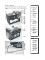
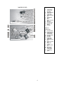
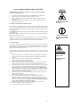
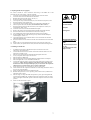
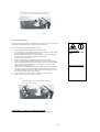
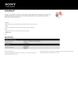
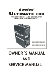
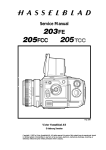
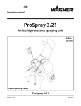
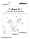
SERVICE MANUAL ULTIMATE 200 This manual is for: 20 200-120 20 200-240 Ultimate 200 std. 120V 60 Hz Ultimate 200 std. 240V 50 Hz 20 201-120 20 201-240 Ultimate 200 DMX 120V 60 Hz Ultimate 200 DMX 240V 50 Hz REFER TO QUALIFIED PERSONNEL ONLY ! NOTE: This service manual describes the most common service & maintenance works. The service and maintenance must be performed by personnel with great experience & knowhow about haze machines in general, and Swefog Ultimate series in particular. Never modify or change anything inside the machine. If any part is replaced, always use Swefog original parts. If not, the manufacturer will not take any responsibility for safety, performance and CE-conformity. Electrical works must be performed by personnel with national and international certificate of workmanship. For information, call Swefog: HELPDESK: Tel: +46 590 122 50/122 00 Fax: +46 590 122 09 e-mail: [email protected] website: www.swefog.com Swefog technology group AB P.O. Box 106, Östra Vägen 6 682 23 FILIPSTAD Sweden TABLE OF CONTENTS MACHINE COMPONENTS 3 Compressor Unit Haze Unit 3 4 SERVICE MANUAL ULTIMATE 200 STD & DMX Connection / Disconnection of internal air tubes 5 5 COMPRESSOR UNIT: 1. General Cleaning 2. Cleaning of intercooler, intercooler fan & air inlet frame 3. Replacing compressor air inlet filter 4. Replacing DMX unit (if equipped) 5. Replacing inlet & outlet air tubes connected to the intercooler 5 6 6 7 8 HAZE UNIT: 1. General Cleaning 2. Check of condensed water in the compressed air filter 3. Cleaning of compressed air filter 4. Cleaning of nozzle unit 5. Replacing the electric motor of the output fan 6. Replacing the tank unit 2 8 9 9 10 10 11 Machine Components: Left side: Use the images below to identify the parts inside Ultimate 300. When ordering spare parts, please note, some parts are sold as “service kits”. Service kits simplifies order of parts, it also reduces the risk that any part needed for service is forgotten. 1 1. 2. 3. 4. 5. 6. 2 3 4 7. 8. 9. 10. 11. 5 6 7 Fan Air tube (to nozzle) Compressed air inlet (quick lock tube fitting) Fan motor Tank unit Intercooler inlet (hot air) Compressed air filter Intercooler outlet (cool air) Compressed air outlet Capacitor Air compressor Right side: 8 12. 13. 14. 9 10 11 Air inlet frame Air inlet filter Mains inlet, fuse & mains switch (image shows standard model). DMX unit (underneath) 15. 16. 17. 18. 12 13 19. 20. XLR connectors (DMX) Mains inlet Mains neutral (N) pin Manual override switch Main switch Fan wires (connected to mains outlet, mains power to haze unit). 14 SERVICE KITS AVAILABLE: • Air filter service kit: the kit includes 3 pcs of an air inlet filter cartridge. Item no. U23-KT1 • Nozzle cleaning service kit: includes 9 rubber gaskets for the small brass nozzles, 1 O-ring gasket for the nozzle body, 1 access hole sealing gasket and 1 nozzle cleaning brush. Item no. U23-KT2 15 16 17 18 19 20 DMX unit (underneath) 3 NOZZLE UNIT: Nozzle unit (assembled): 1. 2. 3. 4. 5. 6. 7. 8. 9. 10. Nozzle unit (assembled) 11. Compressed air inlet (quck lock tube fitting) Nozzle metal plate Access hole rubber gasket Nozzle body (back part) Fluid inlet tube fittings Nut Nozzle body (front part) Fluid tubes Fluid filter holder Fluid filter tube fittings Fluid filter Nozzle unit (disassembled): 12. 13. 14. 15. 16. 17. 18. Nozzle unit (disassembled) 19. 20. 21. 22. 23. 24. 25. 4 Fluid filter holder Nozzle metal plate Compressed air inlet tube fitting Fluid tube fittings Fluid filter Fluid tubes Access hole rubber gasket Nozzle body (front part) Nozzle body (back part) Nozzle body screws Fluid filter holder nuts Brass nozzles Brass nozzle rubber gaskets O-ring sealing gasket Service manual Ultimate 200 std. & DMX: SYMBOLS: NOTE: For all service works described below, always begin with the following precautions and preparations: 1. 2. 3. 4. Disconnect the machine from mains. Disconnect DMX cables (if equipped) Remove the screws that hold the cover plate. Lift the cover off. Remove the two screws that hold the back plate. Bend the back plate outward approx. 2,5 cm (1”). Depending on which part that is going to be serviced or replaced, follow the relevant instructions below. = Information on tools required to perform the service work. Connection / disconnection of internal air tubes: Ultimate hazers are equipped with super-rapid quick lock tube fittings of the industrial type. Connection and disconnection is done in a second, without the need of tools. The tube fittings are Polurethane (PUR) tubes. All PUR tubes used in the Ultimate series are coloured light blue. To disconnect a tube: Pull the ring on the tube fitting towards the fitting, while the tube is pulled out. To connect a tube: Just push the tube into the fitting, the tube will be automatically locked. Ensure the tube is locked. NOTE: Never replace a tube with a different type, made with a divergent material or wrong size. The tubes used in all Swefog machines are tested and approved to stand the temperature variations, dust, oily fluid residues, and the tube size is calibrated. = Important information on the spare parts required before the service work is started. 1. General cleaning: The machine contains several fans and large amount of air goes through the machine during operation. There will be residues of the haze inside the machine, mixed with dust and dirt from the environment where it is used. Regular cleaning service is necessary to keep your machine functioning like new. The haze fluid is oil-based, and cannot be removed with water. Always use a light alcohol-based cleaning liquid or a domestic cleaning spirit and a cloth or paper for cleaning. 1. 2. 3. 4. 5. 6. 7. 8. 9. 10. 11. 12. 13. Clean the top and the sides of the tank. Carefully wipe off all dust from the fluid level window. Make sure not to break the window. Do not push hard against the window. Clean the fan: the fan wheel, inside and outside of the fan housing. Clean bottom of the machine. Clean all surfaces. Clean all sides of the bottom facing the top cover. Remove the back plate (where mains inlet is placed). Clean the surfaces between the back plate and the machine. Put the back plate back and tighten all screws. Check all electrical parts, like the fan motor, mains connectors etc. If any electrical part is oily or dirty, check if it is possible to clean. If not, always replace with original spare parts only. NOTE: Never take unnecessary risks ! Risk of serious personal injury may occur if oily or dirty components are connected to mains. Clean all surfaces of the compressor. Clean the compressor’s fan blades, there are two fans, one in each end of the compressor. Check the compressor, especially the middle grey part (the electric motor), wipe off dust and haze residues. Clean all sides of the inner bottom part of the machine. Check all electrical parts, like the intercooler fan, the DMX electronics (if equipped), switches, mains connectors etc. If any electrical part is oily or dirty, check if it is possible to clean. If not, always replace with original spare parts only. NOTE: Never take unnecessary risks! Risk of serious personal injury may occur if oily or dirty components are connected to mains. Clean inside of the top cover. Test and check all functions on your machine. Check for leakage, dirt or dust inside the machine. Test and check all functions on your machine. 5 TOOLS REQUIRED: Light spirit or an alcoholbased cleaning liquid. Paper or a cloth A small flashlight for inspection. 2. Cleaning of the intercooler, intercooler fan & air inlet frame: A regular cleaning and removal of dust clogging the intercooler is important to maintain good performance of your hazer! The fan draws air through the intercooler and transfers heat from the compressed air out of the machine. An intercooler clogged with dirt and dust will reduce cooling capacity, the result is less haze output and an increased amount of moisture in the compressed air. To clean the intercooler is easy and made in a few minutes. NOTE: NEVER use mechanical or sharp tools, it may damage the thin aluminium plates inside the intercooler! Use compressed air ONLY, and blow off all dirt and dust. TOOLS REQUIRED: PH 2 Screwdriver PZ 1 Screwdriver 1. 2. 3. 4. 5. 6. 7. 8. Loosen the 2 screws that hold the air inlet frame, and remove the frame. Loosen the 2 black screws behind the air inlet frame. Release the two inlet and outlet tubes from the quick-lock tube fittings. Bend the back plate outwards approx. 25 mm (1”). Use compressed air to blow air through the intercooler towards a cloth or a paper. The dirt / dust will come off from the intercooler. Clean the fan. Use paper or a cloth to clean the fan blades. Clean the fan frame. Work the back plate in place, connect the two inlet and outlet tubes and tighten the two black screws at the back of the machine. Put the air inlet frame back in place. 8 mm nut tightener Compressed air @ 6-8 bars, and an air blow gun. Cloth or paper 3. Replacing compressor air inlet filter: 1. 2. 3. 4. 5. 6. 7. Loosen the 2 screws that hold the air inlet frame, and remove the frame. Loosen the 2 black screws behind the air inlet frame. Bend the back plate outwards approx. 25 mm (1”). Work the air filter out of the machine. Open the filter cap (twist it anti-clockwise) Remove the filter cartridge. If necessary, clean inside of the filter housing. Use a cloth or paper and a light alcohol-based cleaning liquid or spirit. NOTE: Don’t let any dust or parts come into the air inlet tube connected to the filter housing – the compressor may be damaged. 8. Replace the old cartridge with a new (never re-use an old cartridge for any reason), original Swefog cartridge, type: SM-L. NOTE: Place the filter cartridge in the filter cap first, then screw the filter cap back in place. 9. Put the filter back in place inside the machine. 10. Tighten the two black screws at the back of the machine. 11. Put the air inlet frame back in place. 6 TOOLS REQUIRED: Paper, cleaning liquid. SPARE PARTS REQUIRED: 1 x Air inlet filter cartridge. The above spare parts included in the U200 service kit available from your dealer. 4. Replacing DMX unit (if equipped): See owner´s manual for correct connection and setting of the DMX unit. If the electronics do not work properly, it must be replaced: 1. Loosen the 2 screws that hold the air inlet frame, and remove the frame. 2. Loosen the 2 black screws behind the air inlet frame. 3. Bend the back plate outwards approx. 25 mm (1”). 4. Work the air filter out of the machine. 5. Cut the plastic stripes around the black (fan) wires and the red (capacitor) wires. 6. Disconnect the fan wires from the fan. 7. Cut the plastic stripe around the capacitor that is attached to the DMX unit. 8. Lift the capacitor out of the machine (do not disconnect the red wires). 9. Disconnect the air tubes from the intercooler; at the compressor´s outlet, and compressed air filter´s inlet. 10. Loosen the 5 black screws that hold the DMX unit plate. 11. Remove the plastic frame (located between the DMX unit and the machine) 12. Disconnect the earth wire connected to the mains inlet’s earth pin. 13. Cut all small black plastic stripes that keep all electrical wires together. 14. Work the DMX unit out of the machine (you may need to bend the backplate outwards approx. 25mm / 1”). 15. Cut the black plastic wires around the electric wires connected to the switches underneath the DMX unit. 16. Disconnect the brown wire from the override switch and the blue wire from mains inlet. 17. Remove the two screws that hold the intercooler, and remove the intercooler 18. Clean all wires, the plastic distance frame, and clean the machine housing inside. Assembling new DMX unit: 1. 2. 3. 4. 5. 6. 7. 8. 9. 10. 11. 12. 13. 14. Assemble the intercooler to the DMX unit (the work will be easier if the intercooler is put upside-down). Connect the brown wire to the override switch and connect the blue wire to the mains inlet´s neutral (N) pin. Place all wires coming out from the DMX unit through the wire hole Use 2,5 mm plastic wire stripes to fix the wires. Place back the new DMX unit. Place back the plastic frame between DMX unit and the machine´s backplate. Place and tighten all 5 screws that hold the DMX unit. Connect the earth wire (yellow / green colour) to the mains inlet’s earth pin (use a long pliers). NOTE: Wrong connection of the electrical wires may cause an electric shock and a serious personal injury! If you do not have the experience and know-how to connect electric wires, contact an electrician. Ensure that no electric wire is squeezed, or close to a sharp edge. Check that the fan and compressor fan blades can rotate freely, and that no cable is close to any of the fan blades. Put the air inlet filter back into the machine housing. Bend the back plate into a correct position; put the 2 black screws, behind the air inlet frame, back in place. Place the long wire stripe that holds the capacitor in place; put it through the left square hole in the DMX unit, around the edge of the compressor plate (see image below), and tighten around the capacitor. Ensure the capacitor is fixed in a correct position. Put the air inlet frame back in place. 7 TOOLS REQUIRED: PH 2 Screwdriver TX 20 Screwdriver Flat pliers Cutting pliers SPARE PARTS REQUIRED: 1 x DMX unit made for 120 or 240V. ~ 20 pcs wire stripes 2,5 mm (1 / 10”) 1 pce wire stripe 350 x 5 mm (Appr. 14 x 1/5 “) 5. Replacing inlet & outlet air tubes connected to the intercooler: There are two tubes connected to the intercooler: Tube between the compressor’s air outlet and intercooler’s inlet: 1. Remove the old tube by releasing it from the compressor (quick lock tube fitting), and from the intercooler (unscrew and release the tube clamp). Be careful not to damage the intercooler’s air inlet pipe (made with copper) when the old tube is removed. 2. If necessary, clean the intercooler’s air inlet pipe. 3. Use a new, Swefog original spare tube. Place the tube clamp around the tube (do not tighten it yet). 4. Put the tube around the intercooler’s inlet copper pipe. To ensure an airtight connection, approx. 20 mm (0,8”) of the copper pipe should be inside the tube. 5. Connect the tube to the compressor’s air outlet (quick lock tube fitting). Ensure an airtight connection. 6. Place the tube clamp around the tube. Tighten the clamp, ensure an airtight connection. TOOLS REQUIRED: 7 mm nut tightener Tube between the intercooler’s outlet and compressed air filter: 1. Remove the old tube by releasing it from the compressed air filter (quick lock tube fitting), and from the intercooler (unscrew and release the tube clamp). 2. Use a new, Swefog original spare tube. 3. Place the tube clamp around the tube (do not tighten it yet). 4. Put the tube around the intercooler’s outlet copper pipe. For a correct position of the tube, approx. 20 mm (0,8”) of the copper pipe should be inside the tube. 5. Connect the tube to the compressed air filter. Ensure an airtight connection. 6. Place the tube clamp around the tube. Tighten the clamp, ensure an airtight connection. Original 10mm PUR tube for connection between intercooler & compressed air filter. A small screwdriver SPARE PARTS REQUIRED: Original 10mm PUR tube for connection between compressor & intercooler 6. Check for condensed water in the compressed air filter: The compressed air filter is the last filter that the compressed air passes before going through the nozzle. The filter separates moisture from the compressed air. While machine is operating, the water will be removed from the air. The water is stored in the filter cup. Every time the machine is switched off, a small valve in the bottom will open to let out the condensed water. Check that everything is working OK and that no water is kept in the cup when the machine is switched off. TOOLS REQUIRED: A small flashlight 7. Cleaning of the compressed air filter: The filter cartridge is made with PE plastic or brass, and be cleaned. 1. Release the air inlet & outlet (nozzle) tubes from the filter. 2. Unscrew the transparent filter cup. Remove the cup from the machine. 3. Unscrew the filter cartridge. 4. Disassemble the filter cartridge, and put all parts in a cup with a light spirit for approx. 1 hour. NOTE: Do NOT use strong spirits for risk of damaging the plastic parts. 5. Clean the filter element from dirt with the use of compressed air. 6. Clean & dry all parts. 7. Clean the rest of the filter & filter cup with a light spirit and a cloth. Make sure that no dirt or dust is left in the filter or filter cartridge. 8. Put the filter cartridge back in place. Ensure that the filter cartridge is tightened properly to the filter body. 9. When the filter cartridge is fixed, put the filter cup back in place. Check the small valve at the bottom of the filter cup. For correct operation, check that the valve closes when the machine (compressor) is switched on, and opens when it is switched off. 8 TOOLS REQUIRED: Light spirit or alcohol-based cleaning liquid in a cup. Combination pliers A small flashlight for inspection. 8. Cleaning of nozzle unit: If your hazer seems to work normally, but haze output is reduced, the V-TEC cracker nozzles may be clogged. Ultimate 200 is equipped with the easyclean feature, allowing for an easy and quick service of the nozzle unit. NOTE: It is very important to perform the cleaning work properly, if the nozzles are not assembled correct, there is a risk of low haze output, and a damaged compressor. 1. 2. 3. 4. 5. 6. 7. 8. 9. 10. 11. 12. 13. 14. 15. 16. 17. 18. 19. 20. Remove the air supply tube. Remove the 4 screws that hold the nozzle plate. Work the nozzle unit out of the tank. Wipe the nozzle unit off with a cloth or paper. Remove the 3 fluid tubes from the nozzle body. Remove the 2 nuts from the back of the nozzle body. Release the plate holding the fluid filter from the nozzle body. Remove the 3 screws in front of the nozzle body. Remove the front part of the nozzle body. Remove the rubber gaskets from the brass nozzles. Carefully clean the 3 brass nozzles by using a small brush (like a toothbrush), and an alcohol based cleaning liquid or spirit. Check and clean the small output hole in the nozzle. Do not leave any dust or dirt inside the nozzle. Clean all sides of the nozzle, do not leave any dirt. Use compressed air to clean the small hole in the brass nozzle Clean the front part of the nozzle body: clean the output holes from dirt. Put the small brass nozzles back; put them in the correct holes in the back part of the nozzle body. NOTE: Do not forget the rubber gaskets: 3 pcs. for each brass nozzle. Put the o-ring gasket back. Put the front part of the nozzle body back. Ensure a correct position. Assemble the 3 screws. NOTE: the upper screw is short, the two lower screws are long. Tighten each screw until there is no gap between the front and back parts of the nozzle body. Then tighten each screw ¼ of a turn more. Check the fluid filter. If it seems to be dirty, replace it with a new one. Normally, the fluid filter does not need to be replaced. Check the fluid tubes between the fluid filter and the nozzle body. If there is dirt inside, the fluid filter (see above) and the tubes must be replaced. Put each tube back in place. Check the sealing gasket that is placed around the access hole on top of the tank, between the tank and the nozzle plate. Now your nozzle unit is as good as new! Put it back through the hole in the tank. Tighten all 4 screws. NOTE: Do NOT tighten too hard – it may damage the sealing gasket. Tighten each screw until there is no gap between the cover plate, the gasket and the tank. Then tighten ¼ of a turn more. TOOLS REQUIRED: PH 2 screwdriver Paper or a cloth 8 mm nut tightener TX 20 screwdriver A small brush, i.e. a toothbrush. Light spirit or alcohol-based cleaning liquid, and a cup for cleaning. Compressed air @ 6-8 bars, and an air blow gun. SPARE PARTS REQUIRED: 3x3 = 9 rubber gaskets for the small brass nozzles* 1 O-ring gasket* 1 sealing gasket around the access hole in the tank* *) = included in the nozzle cleaning service kit, item no. U23-KT2. the above spare parts included in the U23 service kit available from your dealer. 9. Replacing the electric motor of the output fan: If the output fan is not working, check as follows: • Use a voltage meter to ensure mains power is supplied to the fan. If not, check the problem. • If mains power is supplied, and the fan still does not work, check that the fan wheel can be rotated easily. If so, the motor must be replaced. If not, then check and solve the problem. Disconnect from mains before proceeding the operation: 1. 2. 3. 4. 5. 6. 7. 8. Disconnect the two fast-on electric connectors underneath the motor. The motor is fixed with a bayonet system: twist the motor approx. 1/8 of a turn anti-clockwise. When the motor is released, pull it out from the fan wheel. Replace with a new fan motor of the same type and size. NOTE: Use Swefog original spare parts only. Push the motor spindle through the rubber hole in the fan wheel. Place the motor so that it fits into the bayonet holes on the fan housing. Twist the motor approx. 1/8 of a turn clockwise, until the motor is in the right position. Connect the fan cables. Then bend the cable and connector 90° towards the electric coil. Finally, the fan wheel has to be adjusted. Use a screwdriver and adjust the fan wheel until it rotates freely. TOOLS REQUIRED: Voltage meter A screwdriver SPARE PARTS REQUIRED: 1 x fan motor 120 or 240 V 9 Adjust the fan wheel after the new motor is put in place. Use a small screwdriver and bend the wheel to the left. 10. Replacing the tank unit: If the tank is damaged, and there is a fluid leakage, do NOT try to mend it. The oil film from the haze fluid will make the use of glue or silicone impossible. If the tank unit needs to be replaced, proceed as follows: 1. 2. Disconnect the air supply tube connected to the nozzle unit. Use a sharp knife or a razor blade to make a thin cut in the black sealing material, at the front edge of the machine chassis (see image) 3. Carefully bend the fan housing backwards to release the back edge of the tank. Then release the front edge of the tank from the main fixture. 4. Lift the tank out of the machine. 5. Clean the machine housing, especially the plate underneath the tank. 6. Remove any remaining black sealing material in front of the machine housing 7. Clean the bended edge in the front of the machine chassis with an alcohol-based liquid. NOTE: Clean the edge carefully, if not properly cleaned, the sealing material will not stick to the edge. 8. Put the new tank unit into the housing; work the edge under the fan. Ensure the front edge of the tank is put under the edge in front of the machine housing. 9. Use black polurethane (rubber-like) sealing / glue material, and apply a 2-3 mm thick layer on the edge. Silicone will not work. 10. Use a rounded piece of wood (spatula) to spread the sealing material. 11. Remove all waste glue with a spatula or a scrape. Apply PUR glue between the machine housing´s front edge and the tank. NEED HELP ? CONTACT OUR HELPDESK. Tel: +46 590 122 50 /122 00 Fax: +46 590 122 09 e-mail: [email protected] 10 TOOLS REQUIRED: A cut blade knife, or a razor blade SPARE PARTS REQUIRED: 1 x tank unit