1
HOME
SERVICE MANUAL
Model
FK-101
FEBRUARY 2000
CSM-FK101
KONICA BUSINESS TECHNOLOGIES, INC.
HOME
HOME
FK-101
SERVICE MANUAL
FEBRUARY 2000
Used on Konica Model
7020
HOME
IMPORTANT NOTICE
Because of the possible hazards to an inexperienced
person servicing this equipment, as well as the risk of
damage to the equipment, Konica Business Technologies strongly recommends that all servicing be performed by Konica-trained service technicians only.
Changes may have been made to this equipment to
improve its performance after this service manual was
printed. Accordingly, Konica Business Technologies,
Inc., makes no representations or warranties, either
expressed or implied, that the information contained in
this service manual is complete or accurate. It is understood that the user of this manual must assume all risks
or personal injury and/or damage to the equipment while
servicing the equipment for which this service manual
is intended.
Corporate Publications Department
© 2000, KONICA BUSINESS TECHNOLOGIES, INC.
All rights reserved.
Printed in U.S.A.
HOME
CONTENTS
Outline of the Device
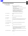
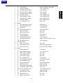
1.1 Basic Specifications .................................................................. 1-1
1.1.1 General Specifications ...................................................................... 1-1
1.1.2 Scanning Section .............................................................................. 1-3
1.1.3 Recording Section ............................................................................. 1-3
1.1.4 Line Connecting Section ................................................................... 1-5
1.1.5 Operation Panel ................................................................................ 1-5
1.2 Functional Specifications ........................................................... 1-7
1.2.1 Dial functions .................................................................................... 1-7
1.2.2 Transmission ..................................................................................... 1-9
1.2.3 Polling ............................................................................................. 1-11
1.2.4 Line Seizure Mode and Telephone Function ................................... 1-13
1.2.5 Message Reception and Record ..................................................... 1-13
1.2.6 Memory Function ............................................................................ 1-13
1.2.7 Various Communication Function ................................................... 1-14
1.2.8 User Lists / Reports ........................................................................ 1-15
1.2.9 Other User Functions ...................................................................... 1-17
1.2.10 Service Mode Function ................................................................. 1-17
1.2.11 FAX Service Counter .................................................................... 1-17
1.3 Components Location ........................................................................ 1-17
1.4 Inhibited Combinations ...................................................................... 1-18
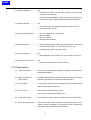
2. Outline of Operations
2.1 Operation Menu ......................................................................... 2-1
2.1.1 Menu for Users.................................................................................. 2-1
2.1.2 Menu for Service ............................................................................... 2-3
2.2 Buzzer Sound............................................................................. 2-6
2.2.1 Kinds ................................................................................................. 2-6
2.2.2 Pattern .............................................................................................. 2-6
3. Service Mode
3.1 Outline of Service Mode ............................................................. 3-1
3.1.1 Service Mode and Test Mode ........................................................... 3-1
3.1.2 Service Mode Menu Tree .................................................................. 3-1
3.1.3 How to Enter the Service Mode ........................................................ 3-2
HOME
3.2 Function Parameter Setting........................................................ 3-3
3.2.1 Modem/NCU ..................................................................................... 3-3
3.2.2 Communication ................................................................................. 3-7
3.2.3 Network ........................................................................................... 3-11
3.2.4 List Output Mode ............................................................................. 3-15
3.2.5 System ............................................................................................ 3-17
3.2.6 Machine Setting .............................................................................. 3-23
3.3 List Print ...................................................................................3-25
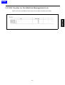
3.4 FAX Counter on the Machine Management List ...................... 3-27
3.5 FAX File Format ....................................................................... 3-28
3.6 Initialization ..............................................................................3-29
4. Test Mode
4.1 Outline of the Test Mode ............................................................ 4-1
4.1.1 Service Mode and Test Mode ........................................................... 4-1
4.1.2 Test Mode Menu Tree ........................................................................ 4-1
4.1.3 How to Enter the Test Mode .............................................................. 4-3
4.2 Signal Sending Test.................................................................... 4-5
4.3 Signal Receiving Test ................................................................ 4-7
4.4 NCU Test ................................................................................... 4-9
5. Troubleshooting
5.1 Error Codes ................................................................................5-1
5.2 Diagnostic Codes ..................................................................... 5-10
5.2.1 Outline ............................................................................................. 5-10
5.2.2 Explanation ..................................................................................... 5-10
5.3 FAX Board Hardware Self-diagnosis ........................................ 5-19
5.4 Countermeasures in Case of No Error Codes ......................... 5-20
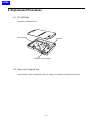
6. Replacement Procedure
6.1 FK-101 Body and Related Items ................................................ 6-1
6.1.1 Removal of the FK-101 Body ............................................................ 6-1
6.1.2 Replacement of Battery .................................................................... 6-3
6.1.3 Replacement of the FAX Control Board ............................................ 6-5
6.1.4 Replacement of the NCU Board ....................................................... 6-5
6.2 One-touch Program Key and Speaker ....................................... 6-6
6.2.1 Replacement of One-touch program Program Key ........................... 6-6
6.2.2 Replacement of the Speaker ............................................................ 6-7
HOME
7. Communication Control
7.1 Protocol ...................................................................................... 7-1
7.1.1 FIF bits of DIS, DTC and DCS .......................................................... 7-1
7.1.2 Modem Fallback Sequence ............................................................... 7-7
7.1.3 V8/V34 Sequence ............................................................................. 7-9
7.2 Telephone Function .................................................................. 7-21
7.2.1 TEL/FAX Switching ......................................................................... 7-21
8. Explanation of Functions
8.1 F-Code ....................................................................................... 8-1
8.1.1 F-Code Confidential Transmission .................................................... 8-3
8.1.2 F-Code Bulletin Board Polling ........................................................... 8-3
8.1.3 F-Code Relay Transmission .............................................................. 8-5
8.2 Transmission Function................................................................ 8-7
8.2.1 Original Scan Mode .......................................................................... 8-7
8.2.2 Book Transmission ............................................................................ 8-7
8.2.3 Restored Transmission ...................................................................... 8-8
8.2.4 Instant Batch Transmission ............................................................... 8-9
8.2.5 Forwarding Transmission ................................................................ 8-10
8.3 Reception Function .................................................................. 8-11
8.3.1 Reduction / Division of Reception ................................................... 8-11
8.3.2 Cassette / Paper Selection.............................................................. 8-13
8.3.3 Forced Memory Reception .............................................................. 8-13
8.3.4 Closed Reception (Junk FAX) ......................................................... 8-14
8.4 Management Function ............................................................. 8-15
8.4.1 Operation without the Key Counter ................................................. 8-15
8.5 Service Function ......................................................................8-17
8.5.1 F-Code Forwarding Transmission .................................................. 8-17
9. Description of Operation
9.1 Dual Access Matrix .................................................................... 9-1
Appendix 1 Wiring Diagram...............................................A1-1
Appendix 2 Address Parameter List.................................A2-1
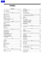
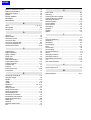
INDEX
HOME
Blank page
HOME
SAFETY PRECAUTIONS
effect may be caused by altering any aspect of the
machine’s design. Such changes have the potential
of degrading product performance and reducing
safety margins.
Installation Environment
Safety considerations usually are directed toward
machine design and the possibility of human error. In
addition, the environment in which a machine is operated must not be overlooked as a potential safety
hazard.
For these reasons, installation of any modification not
specifically authorized by Konica Business Machines
U.S.A., Inc., is strictly prohibited.
Most electrical equipment is safe when installed in a
normal environment. However, if the environment is
different from what most people consider to be normal, it is conceivable that the combination of the
machine and the room air could present a hazardous
combination. This is because heat (such as from
fusing units) and electrical arcs (which can occur
inside switches) have the ability to ignite flammable
substances, including air.
The following list of prohibited actions is not all-inclusive, but demonstrates the intent of this policy.
When installing a machine, check to see if there
is anything nearby which suggests that a potential hazard might exist. For example, a laboratory
might use organic compounds which, when they
evaporate, make the room air volatile. Potentially dangerous conditions might be seen or smelled. The
presence of substances such as cleaners, paint thinners, gasoline, alcohol, solvents, explosives, or similar items should be cause for concern.
If conditions such as these exist, take appropriate
action, such as one of the following suggestions.
•
Determine that the environment is controlled
(such as through the use of an exhaust hood) so
that an offending substance or its fumes cannot
reach the machine.
•
Using an extension cord or any unauthorized
power cord adapter.
•
Installing any fuse whose rating and physical size
differs from that originally installed.
•
Using wire, paper clips, solder, etc., to replace or
eliminate any fuse (including temperature fuses).
•
Removing (except for replacement) any air filter.
•
Defeating the operation of relays by any means
(such as wedging paper between contacts).
•
Causing the machine to operate in a fashion other
than as it was designed.
•
Making any change which might have a chance
of defeating built-in safety features.
•
Using any unspecified replacement parts.
General Safety Guidelines
The specific remedy will vary from site to site, but the
principles remain the same. To avoid the risk of injury
or damage, be alert for changes in the environment
when performing subsequent service on any machine, and take appropriate action.
This copier has been examined in accordance with
the laws pertaining to various product safety regulations prior to leaving the manufacturing facility to
protect the operators and service personnel from
injury. However, as with any operating device, components will break down through the wear-and-tear of
everyday use, as will additional safety discrepancies
be discovered. For this reason, it is important that the
technician periodically performs safety checks on the
copier to maintain optimum reliability and safety.
Unauthorized Modifications
The following checks, not all-inclusive, should be
made during each service call:
•
Remove the offending substance.
•
Install the machine in a different location.
CAUTION: Avoid injury. Ensure that the copier is
disconnected from its power source before continuing.
Konica copiers have gained a reputation for being
reliable products. This has been attained by a combination of outstanding design and a knowledgeable
service force.
The design of the copier is extremely important. It is
the design process that determines tolerances and
safety margins for mechanical, electrical, and electronic aspects. It is not reasonable to expect individuals not involved in product engineering to know what
vii
•
Look for sharp edges, burrs, and damage on all
external covers and copier frame.
•
Inspect all cover hinges for wear (loose or broken).
•
Inspect cables for wear, frays, or pinched areas.
HOME
•
Ensure that the power cord insulation is not damaged (no exposed electrical conductors).
•
Ensure that the power cord is properly mounted
to the frame by cord clamps.
•
Check the continuity from the round lug (GND) of
the power cord to the frame of the copier -- ensure
continuity. An improperly grounded machine can
cause an electrically-charged machine frame.
Safeguards During Service Calls
Confirm that all screws, parts, and wiring which are
removed during maintenance are installed in their
original positions.
•
When disconnecting connectors, do not pull the
wiring, particularly on AC line wiring and high
voltage parts.
•
Do not route the power cord where it is likely to
be stepped on or crushed.
•
Carefully remove all toner and dirt adhering to any
electrical units or electrodes.
•
After part replacement or repair work, route the
wiring in such a way that it does not contact any
burrs or sharp edges.
•
Do not make any adjustments outside of the
specified range.
viii
Applying Isopropyl Alcohol
Care should be exercised when using isopropyl alcohol, due to its flammability. When using alcohol to
clean parts, observe the following precautions:
•
Remove power from the equipment.
•
Use alcohol in small quantities to avoid spillage
or puddling. Any spillage should be cleaned up
with rags and disposed of properly.
•
Be sure that there is adequate ventilation.
•
Allow a surface which has been in contact with
alcohol to dry for a few minutes to ensure that the
alcohol has evaporated completely before applying power or installing covers.
Summary
It is the responsibility of every technician to use professional skills when servicing Konica products. There
are no short cuts to high-quality service. Each copier
must be thoroughly inspected with respect to safety
considerations as part of every routine service call.
The operability of the copier, and more importantly,
the safety of those who operate or service the copier,
are directly dependent upon the conscientious effort
of each and every technician.
Remember...when performing service calls, use good
judgement (have a watchful eye) to identify safety
hazards or potential safety hazards that may be present, and correct these problem areas as they are
identified -- the safety of those who operate the copier
as well as those who service the copier depend on it!
HOME
1
Outline of the Device
HOME
HOME
1.1 Basic Specifications
1.1.1 General Specifications
(1) Applicable lines ................... PSTN
F network (1300H receptions are possible.Only Japan)
(2) Protocol ............................... Group 3 (compliant to ITU-T T.30)
• ECM
• F-code communication
• Konica non-standard protocol : No
• Group 4 : No
(3) Maximum data rate.............. 33,600bps
(4) Coding method .................... MH, MR and MMR
(5) Modulation method .............. V27ter, V29, (V.33), V17, V8 and V34
• V.33 is for reception only.
8 × 3.85 lines / mm
(6) Communication resolution ... Normal
Fine
8 × 7.7 lines / mm
Super fine
8 × 15.4 lines / mm (reception only)
Super fine
16 × 15.4 lines / mm
Fine
200 × 200 pixels / inch
Super fine
400 × 400 pixels / inch
• Fixed to mm at transmission
• mm and inch are available at reception.
• Selection by using the [RESOLUTION] key.
• You can not change settings on every page.
(7) Fax memory size ................. 2 Mbyte Standard (allocated in the ERDH memory )
•
In case of standard ERDH memory (32Mbyte): 4 Mbyte maximum. Possible to add in steps of 2 Mbyte
• In case of ERDH memory expansion (even 1 piece) : 16 Mbyte
maximum.
(8) FAX memory backup ........... Yes
Within 60 minutes (when batteries are full)
• Secondary battery
• Charging time: 28 hours
• Life: charging and discharging 5000 times
1-1
HOME
(9) Multiple line connection ....... No
(10) Communication time ........... Approx. 3 seconds (Konica standard A4 chart, 28,800bps)
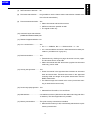
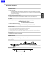
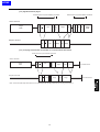
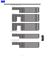
(11) Resolution conversion
Density Conversion
Communication
inch
inch→mm
mm
Communication
Density Conversion
mm
mm→inch
inch
inch
inch→inch
inch
Scanner
At Sending
At Receiving
Print
1.1.2 Scanning Section
(1) Scanning method ................ Platen documents
• Possible to scan book documents (book mode)
RADF book documents
• In case of the platen machine, it is required to attach an RADF
option when the FAX kit is attached.
• Scanning mode: One sided, Two sided and Cover+2sided
• Possible to scan the RADF mixed size documents.
8 × 3.85 lines/mm
(2) Scanning resolution ............. Normal
Fine
8 × 7.7 lines/mm
Super fine
16 × 15.4 lines /mm
• Selection by using the [Resolution] key.
• You can not change settings on each page.
(3) Mixed size original ............... Possible to mix documents of different sizes.
• After rotation of images, sizes are changed by EOM every time
the length of the scan line is changed at sending.
• Possible to mix sizes (A and B).
(4) Density selection ................. Selection by using the [Density] key. [Lighter] / [Darker] / [Normal] / [Auto]
• You can not change settings on each page.
(5) Maximum scanning document width ..... 297 mm (A3 width) both for RADF and Platen
(6) Maximum scanning document length ... 420mm (A3 length) / (17 inch double letter) in the regular mode
• 800 mm
1-2
at the maximum Long original mode by ADF
HOME
(7) Effective scanning range ..... Compliant to the copier standard
When a document is smaller than the effective scanning area, the
area outside the document is erased.
• ADF scanning
: left, right, head and bottom Mask of 3mm
each (0 to 5mm)
• Platen scanning
: left, right and head Mask of 2mm each
(fixed)
(8) Automatic reduction at sending .... A3 → B4, A3 → A4 and B4 → A4
• Automatically reduced and sent in accordance with the recording paper size of remote station.
(9) Rotation transmission .......... A4 size only. SEF documents are rotated by 90 degrees at sending
to send it in LEF direction.
(10) Page division at sending ..... No
(11) Halftone ............................... 256 level error diffusion
• Users can change settings by using the [Quality] key.
(12) Automatic Background Contool (ABC) . Yes
(13) Finished stamp .................... No
(14) Scanning time...................... 2.0 seconds (A4/LEF)
(15) Automatic feeder capacity ....... Compliant to the copier standards
1.1.3 Recording Section
(1) Recording ............................ Compliant to the copier standards
(2) Recording paper size .......... All sizes except for B6 and Postcard (Refer to the copier basic specifications.) Auto recording paper selection
Note:A5 and B5 paper is used only for A5 and B5 reception respectively
(3) Recording paper cassette ... Tray 1 to Tray 4, bypass Tray.
(4) Staple .................................... No
1-3
HOME
(5) Recording speed ................... Compliant to the copier standards
(6) Recording size ..................... A3 size maximum
• A3 fix as reception record ability declaration in protocol.
(7) Maximum reception length .. 840mm
• In case of being larger than the maximum reception length, a
communication error occurs.
• When the memory over occurs during reception, the received
data is printed.
(8) Reduction record ................. When the received image information is larger than the recording
paper, it is automatically reduced to the recording paper size and
recorded.
(9) Page separation record ....... Yes
(10) Offset output at each communication .. Yes (Job unit reception only)
(11) Rotation reception ............... Yes
• Images are rotated by 90 degrees and recorded on the recording paper in LEF direction.
(12) Two-sided reception ............ Yes (Key operator mode)
(13) 2-in-1 reception ................... Print A4 × 2 →A3, B5 × 2 →B4 and A5 × 2 →A4
• When there are no regular sizes in the auto print setting, the 2in-1 reception is not used.
• Two-sided reception has a precedence when both are specified.
(14) Smoothing ........................... Yes
(at converting the resolution)
(15) Multiple copies recording .... No
(16) Bypass print ......................... Possible to use as an active tray in auto selection mode.
(17) Total page counter ............... Compliant to the Copier standards
(18) Monitor print ........................ No
(copy at sending)
1-4
HOME
1.1.4 Line Connecting Section
(1) NCU type ............................. A-A~ and built-in NCU
(2) Connecting terminal ............ RJ11
(3) Modem ................................ Matsushita MMD-H3500
(4) Modem sending level .......... -10~-15 dBm (Country spec)
(5) DTMF sending level ............ -10~-15 dBm (Country spec)
(6) Receiving sensitivity ............ G3 reception: -43dB or less
Tone reception: -52dB or less
(7) Dialing signal ....................... DP (10pps and 20pps) and DTMF
1.1.5 Operation Panel
(1) FAX/Copy/Printer
Mode switching .................... By panel key selection
• Possible to change modes during an operation of each mode.
• No mode return by the auto reset.
• A copy screen is shown when the power is turned on.
(2) Interruption during scanning .......... Operations by using the INTERRUPT button while scanning documents to be transmitted are invalid.
(3) Interruption during
recording in the FAX mode screen ... Operations by using the INTERRUPT button are invalid.
(4) FAX start .............................. By using the START button.
• START button in needed for the one-touch key.
(5) Stop ..................................... By using the STOP button.
• Possible to appoint to stop from the job list so as to stop during
operations of the multi jobs.
(6) FAX free memory display .... Yes
% indication on LCD during scanning, recording and stand-by.
1-5
HOME
(7) File existance indication ........ By DATA LED
• Files to be displayed are the reception files, transmission reservation files, polling reception reservation files and printer files
• Light off: There are no files.
• Light on: There are files.
(8) Display during the
FAX communications ........... Icons are displayed on the FAX waiting screen and the FAX operation screen.
(9) Error display ........................ Displayed by LED on FAX mode button.
Green: There are no errors.
Red:
There are errors.
Error indication:
all errors
(10) Time display ........................ No
• Present time is displayed on the timer communication setting
screen.
(11) Remote station ID display ... Yes
• The number display function can be used before communications (Japan only).
• The TSI/CSI display during communications
(12) Other operation buttons ...... APPLICATION button: Moves to the FAX application function setting screen.
OUTPUT button:
Invalid
CHECK button:
Valid
*/# button:
Yes
HELP button:
Yes
One-touch key:
20 keys
1-6
HOME
1.2 Functional Specifications
1.2.1 Dial Functions
(1) Abbreviated dial ................... Yes
• Possible to register 200 stations.
• Possible to appoint extension / external types.
• 38 digits maximum
• Possible to search the remote station list in the order of abbreviation numbers and names.
• The registration names must be 24 digits or less.
• Registration name auto registration function: No
• Second FAX No. registration function: No
• Possible to register the communication mode.
• Possible to register a part of application functions.
(2) One-touch dial ..................... From the LCD touch panel or the one-touch keys.
20 keys.
(3) Program dial ........................ Yes
The LCD touch-panel or one-touch key is used.
(4) Key pad dial ......................... 38 digits maximum
(5) Group dial ............................ Yes. Up to 20 groups. Possible to register group names. Up to 200
remote stations per each group by abbreviated numbers only.
(6) Chain dial / Additional dial ............. No
(7) Dialing of multiple remote stations ...... 210 remote stations maximum (abbreviated 200 + key pad 10)
(8) Manual redial ....................... Yes
• Possible to select from five latest histories.
(9) Automatic redial ................... Yes
• Automatically redial when remote stations are busy or return no responses or transmission errors occur at the memory transmission
• Possible to receive during redial waiting.
• Anotner call is possible. (Not possible when there are two redial
waiting jobs.)
(10) Pulse/Tone switching ........... Possible to switch by using the [Tone] key on the [Key pad] screen
of the LCD.
1-7
HOME
(11) PBX mode setting ............... Yes
• Possible to turn On or Off the PBX connection and to register
the external access code.
• There are automatic addition / automatic removal functions of external access code to registered abbreviated remote station No.
(12) Pseudo off-hook .................. Yes
• The manual start is possible by using the pseudo off-hook.
• [Off hook] button on LCD
(13) Call progress detection ....... • DC loop (Depends on country spec).
• Dial tone (Ditto)
• Busy tone (Ditto)
• Second dial tone (Ditto)
(14) Dial parameters ................... • Dialing signals DP (10pps and 20pps) and DTMF (Depends on country spec)
• Pause between digits 1 to 7 seconds (Users can set.)
• Pause between digits 3 seconds (fixed)
(15) Phone book dial .................. Yes
• After appointing one character, use up and down cursor keys.
(16) External phone connection jack ............ Yes
• Depends on specifications of each country.
1.2.2 Transmission
(1) Timer transmission .............. 24-hour (max.) timer setting is possible. (one station, sequential multistations transmission)
(2) Batch transmission .............. Possible to transmit data in a batch with the same set time, all remote
(Timer batch)
stations, international communications and resolution.
(3) Timer polling ........................ 24-hour (max.) timer setting is possible. (one remote station polling
and sequential polling reception)
(4) No. of timers ........................ 20 transmissions and pollings in total
The number of sequential pollings is one.
(5) Reservation report .............. The reservation report output is possible at the timer reservation.
(6) Memory transmission reservation ...... The memory transmission reservation is possible during communications. (memory registration of the RADF memory transmission
and platen memory transmission documents)
1-8
HOME
(7) RADF transmission reservation .... No
(8) Fold erase transmission ...... No (possible to use the frame erasure transmission instead at the
time of book transmission)
(9) Frame erase transmission ... Yes
• Platen documents and book documents
• ADF documents are possible as well.
• The regular mode only
(10) Automatic layout transmission
(Outside documents are erased.)..No
(11) Reverse-image transmission...No
(12) 2-in-1 transmission .............. Yes
• A4 × 2 → A3/B4/A4, B5 × 2 → B4/A4 and A5 × 2 → A4
• 2-in-1 and 2-sided are exclusive. 2-sided transmission takes precedence. (2-sided menu is gray-out.)
(13) Book transmission ............... Yes
• Transmission by dividing one page document into two pages.
The document size is A3 and B4.
• Platen documents and ADF documents (regular-size document
mode only) can be used.
(14) Scanning size appointment ............ Yes
• Scans documents in the appointed size irrelevant to document
sizes and sends them. Transmits documents in the appointed
scanning width and length at the platen transmission and the
RADF transmission.
• The effective image area is based on the center. (Corner-base scanning in mixed-size document mode.)
(15) Document image quality appointment .. Yes
• Selected from Photo/line, Line and Photo.
(16) Multi-stations ....................... 210 stations maximum (Abbr dial ✕ 200 stations and key pad dial ✕
10 stations) The timer appointment is possible.
(17) Memory transmission .......... The quick memory transmission is default.
• When the FAX memory is full, automatically switched to the quick
memory transmission.
1-9
HOME
RADF
Transmission
Yes
✕ No
Partly Yes
Platen Transmission
Quick
Memory
Transmission
One page only
Memory
Transmission
After pressing the
SCAN button to scan,
press the START key
to start communications.
Mixture of RADF/
Platen Documents
Advanced
Communication Manual
Transmission
Function
Transmission
When the Printer
is Active
(Only the communication
mode is possible.)
After pressing the
SCAN button to scan,
press the START key
to start communications.
(18) Forwarding transmission ..... Yes
• Automatic forward: Automatic forward of received documents to
remote stations registered in advance.
• Manual forward: Manual forward of documents of substitute reception.
(19) Interruption transmission ..... Single station transmission reservation automatically interrupts between stations of multiple station communications.
(20) International
communication .................... Yes
• When the remote station is V17, communications start at TCM
7,200bps. When the remote station is V34, they start at
28,800bps.
(21) V34-off transmission ........... Transmitted without V34 mode. The V34-off appointment can be registered in the abbreviated / program dials.
This is used when the transmission error code related to V34 occurs frequently.
(22) Long original transmission .. Possible to transmit long-length originals of 800mm maximum.
(23) ADF irregular-size transmission ..... Possible to transmit irregular-size documents from ADF. The main
scanning is the max. document width set on ADF, and the sub scanning depends on document length. The maximum is 420 mm/17
inch.
(24) Restored transmission ......... Keep the transmission file causing the redial over / communication
error for a designated time period in order to re-send it.
• Remote station No. is changeable.
• The file keeping time is selected from 12/24/48/72H.
• Only at the memory transmission is effevtive. (Not for quick
memory transmission)
1-10
HOME
(25)Instant batch transmission ... All reserved documents to the same remote station are sent in a batch.
(Bundled transmission)
•
Not effective with the job being transmitted.
•
Abbreviated dialing and key-pad dialing are recognized
as a different station even if developed number is same.
(26) Confidential transmission ............... Transmission to the confidential BOX of a remote station by using
the F code (SUB/SID). Appoints the confidential BOX No. by using
SUB. Possible to select the SID sending Yes / No on the control
panel.
(27) Relay request ...................... The relay request by using the F-code (SUB/SID). Appoints the relay BOX No. by using SUB.
(28) Relay transmission .............. The relay transmission by using the F-code (SUB/SID). Registers
final relay stations (group) in the relay BOX in advance. When the
relay BOX is appointed by SUB, transmits to the registered relay
group. After the relay transmission, files in the relay BOX are deleted. SID is essential.
1.2.3 Polling
(1) Polled transmission ............. There is one documents which allows the transmission setting.
• Documents are deleted after transmission.
• No additional scanning of documents
• No RADF polled transmission reservation
(2) Polling reception .................. The sequential polling is possible.
210 stations maximum (abbreviated dial × 200 stations and key pad
dialing × 10 stations) Appointment of the 24-hour (max.) timer is
possible.
(3) Call turnaround polling ........ No
(4) Called turnaround polling .... Yes
(5) Closed polling transmission No
(6) Selective polling .................. Transmission and reception.
The selective polling by using the F-code (SEP). There is a bulletin
board BOX polling reception. No confidential BOX polling transmission
1-11
HOME
1.2.4 Line Seizure Mode and Telephone Function
(1) Line seizure mode switching Possible to set the automatic reception and the manual reception.
• When the memory is full and there are no polling transmission
reservations, the automatic reception mode is cancelled.
• No switching of the auto / manual mode by appointing data and
time
(2) Ans. Machine mode ............. Yes
• At the time of the CNG detection with the external phone off
hook, a line is caught to start reception.
(3) Automatic reception mode .. Time and the number of rings.
• No. of rings : 0 to 15 times (country spec)
• Time
: 0 to 15 secs (country spec)
(4) Hold ..................................... No
(5) Handset ............................... No
(6) One-piece phone ................. Country spec
(7) Conversation reservation .... No
(8) Caller ID display (NTT service) ...... The number display is possible. Japan only
(9) Dial in service ...................... Yes. Japan only
(10) Remote reception ................ Yes. 2-digit PB signal. Japan only.
1.2.5 Message Reception and Record
(1) Confidential reception ......... Reception at the confidential BOX appointed at the F-code (SUB).
You can select the SID check on communications. At the time of
printing documents received at the confidential BOX, a password to
access to the confidential BOX is required.
(2) Closed reception ................. Closed reception by using the SID (PWD) (Junk FAX)
1-12
HOME
(3) Adaptive (automatic) reduction ...... 35 to 96%
in steps of 1%
Becomes the adaptive reduction when "Page devided print = OFF"
is selected. In case of the adaptive reduction, if the reception image
size is a little bigger than recording paper, the size is automatically
reduced so that it becomes within the recording paper size and is
recorded.
(4) Fixed reduction .................... No
(5) Page separation record ....... Dose not overlap at the division.
(6) Equal size recording ............ Sent documents are recorded in the equal size (100%).
For bigger size documents, an appropriate tray is searched. For A3
or bigger documents, a part of documents are abandoned.
(7) Back end margin disposal ... No
(8) Cassette selection ............... Appropriate paper size auto selection
• When paper is running out, paper is provided from another cassette with the same size of paper.
• Tray-fix mode available
(9) Index print ............................ No
(10) 2-in-1 reception ................... Yes
• A4 × 2 → A3, B5 × 2 → B4 and A5 × 2 → A4
• 2-sided reception is not done when there are no regular sizes or
when one page is received.
1.2.6 Memory Function
(1) Display of used memory space ...... Yes
(2) Forced memory reception ....... A password is required for printing received files. The password (four
digits) is set when the forced memory reception mode is set in the
key operation mode.
(3) Memory substitute reception ... Yes (when there is no paper / no toner)
(4) Dual access ......................... Refer to 9.1.
(5) Reception multi copy ........... No
1-13
HOME
1.2.7 Various Communication Function
(1) Short protocol ...................... No
(2) ECM..................................... Yes
• Window size: 16k byte / 64k byte
(3) Communication timer .......... Yes
• 24 hours maximum. 20 timers including one sequential polling
timer 20 units.
(4) Redial waiting ...................... Two redial timers maximum
(5) Error page resending .......... No (becomes the error page redial.)
(6) Error page redial ................. Effective to both quick memory transmission and memory transmission. Redial and retransmission in case of RTN or comm error.
• Redial interval: follows the busy redial interval.
• Num. of redials: 0 to 7 times (different counter from the busy
redial)
(7) Total page number print ...... Yes
• Automatic print to the TTI in memory transmission.
• Added when the number of document pages is appointed for
quick memory transmission.
(8) Header memo ...................... No
(9) TTI (Transmitting Terminal ID) ........ Yes
• 30 characters maximum
• Added to the top of the sending images, not to the scanned document images when the image rotation or 2-in-1 is appointed.
(When 2-in-1 is appointed, the TTI page becomes the page in
the communication.)
(10) RTI (Receiving Terminal ID) .... Yes
• Recorded at the bottom before the image rotation / 2-in-1 combination are performed after processes for expansion or reduction
• Date, time and page no. are recorded.
(11) Remote diagnosis ................ Read / Write
(12) MH fix .................................. No
(13) Urgent document sending mode...........No
1-14
HOME
(14) Document insertion after dialing .................Yes
Document insertion is possible after dialing.
Starts calling by using the [Start] button.
(15) Communication history ........ Yes
The last 100 communication histories are recorded in the communication journal.
(16) Machine communication
management .......................Yes
• The total number of sent pages, received pages, no. of transmissions and no. of receptions are respectively shown in the management list (for service).
(17) Electronic key counter ......... Yes
• The number of transmitted pages to each user. Limit control is
not done.
(18) Key counter.......................... Yes
• When the key counter is not attached, use the parameter setting
for the transmission operation.
The reception and recording are performed
(20) Coin vender ......................... No
• It is impossible to use with FAX.
1.2.8 User Lists / Reports
(1)
Communication Journal .................... The total of 100 communications (sending and reception)
can be recorded.
Automatic output ... at Every 100 com / daily / at Every 100 & daily
Manual output ....... Yes
(2)
Transmit reserve report ..................... Automatic output Users can turn ON / OFF.
(3)
Transmit report .................................. Automatic output (Always / Only on error / Users can turn OFF)
Possible to output with images
(4)
Polled Tx reserve report .........................Automatic output
Users can turn ON / OFF.
(5)
Polled Tx result report ....................... Automatic output
Users can turn ON / OFF.
1-15
HOME
(6)
Sync transmit reservation report ....... Automatic output
Users can turn ON / OFF.
(7)
Sync transmit result report ................ Automatic output
Users can turn ON / OFF.
(8)
Polled Rx reserve report ................... Automatic output
Users can turn ON / OFF.
(9)
Sequential poll, Rx reservation report .... Automatic output
Users can turn ON / OFF.
(10) Sequential poll, Rx result report .......... Automatic output
Users can turn ON / OFF.
(11) Confidential Rx report ....................... Manual output (numeric order or alphabetic order)
(12) Polled Tx result report ....................... Manual output
(13) Relay Request Rx report ................... Manual output
(14) Relay Sync Tx result report ............... Manual output
(15) Abbr dial list ....................................... No
(16) Program entery list ............................ Yes (No responses to requesting stations)
(17) Group dial list .................................... Auto output at the F code confidential reception
(18) Fax setting list ........................................... Yes
1.2.9 Other User Functions
(1)
Fax ID ................................................ Number ID: 20 digits (max.)
(2)
Header note ....................................... No
(3)
Language selection ........................... Yes
1.2.10 Service Mode Function
Refer to the Chapter 2 for details
1.2.11 FAX Service Counter
•
FAX counts by each paper size
•
Counts for the communication system
Refer to 3.4 for details.
1-16
HOME
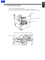
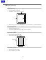
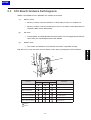
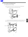
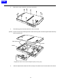
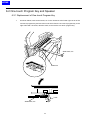
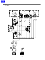
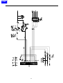
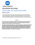
1.3 Components Location
The location of the FK-101 is shown as follows.
The FK-101 body is attached to the lower-left corner of the back side of the Copier.
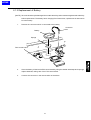
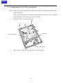
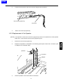
The one-touch program keys and the speaker are located at the upper-left corner of the Copier.
Housing Box
FK-101 Controller Board
NCU Board
Location of the One-touch Program Keys and the Speaker
One-touch Program keys
Speaker
1-17
HOME
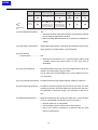
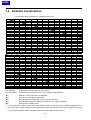
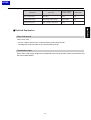
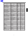
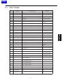
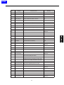
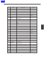
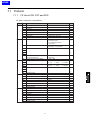
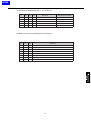
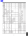
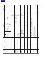
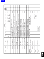
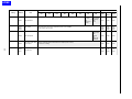
1.4 Inhibited Combinations
The following show combinations of application functions.
Second
First
Memory transmission
2-in-1 Tx
Book transmission
Frame erase transmission
Original size select
Total page setting
Mixed size original
Z fold documents
Irregular documents
Long length
documents
Edge correction
Polled transmission
Memory transmission
2-in-1 Tx
Auto selection
(▼1)
Book transmission
Auto selection
(▼2)
Frame erase transmission
Auto selection
Original size select
Auto selection
Total page setting
Auto cancellation
Mixed size original
Auto selection
(▼3)
Auto selection
(▼4)
Auto selection
Auto selection
Auto selection
Auto selection
Z fold documents
Irregular documents
Long length documents
Edge correction
Polled transmission
Auto selection
Polling reception
Timer transmission
Auto selection
Int'l com mode
ECM OFF
V.34 OFF
Confidential transmission
Bulletin board
Relay request
Two sided
Cover+2sided
Auto selection
Platen
(▼5)
Second
First
Polling reception
Timer transmission
(▼5)
Int'l com mode
ECM OFF
V.34 OFF
Confidential transmission
Bulletin board
Relay request
Two sided
Cover+2sided
(▼5)
Platen
Document scanning
Memory transmission
2-in-1 Tx
Book transmission
Frame erase transmission
Original size select
Total page setting
Auto cancellation
Mixed size original
Z fold documents
Irregular documents
Long length documents
Auto selectio
Edge correction
Polled transmission
Polling reception
Timer transmission
Int'l com mode
ECM OFF
V.34 OFF
Confidential transmission
Bulletin board
Relay request
Two sided
Auto cancellation
Auto cancellation
Cover+2sided
Auto cancellation
Auto cancellation
Platen
Auto selection
: Automatically selects a memory transmission.
Auto cancellation : Automatically cancels the function which was previously selected.
(▼1)
: B6R, B4, A3 and Legal are not selectable.
(▼2)
: Only B4, A3 and Legal are selectable.
(▼3)
: Not selectable when B6R, B4, A3 and Legal are selected.
(▼4)
: Not selectable when other paper sizes than B4, A3, Legal are selected.
(▼5)
: Changed to the RADF mode.
• On the application function screen shown while pausing the document scanning, the selected application function buttons are inverted in black and other advanced function buttons which can no be changed become gray
out. (The document size can be changed at selection of mixed size documents only.)
1-18
HOME
2
Outline of Operations
HOME
HOME
2.1 Operation Menu
2.1.1 Menu for Users
Abbr No. entry / edit
[Remote station
list] tab
Fax main menu
Remote station registration menu
Abbr No. list / search
Program entry / edit
Program list
[Key pad] tab
Program registration / edit menu
Program list menu
Group entry / edit
Relay entry / edit
Confiden entry / edit
Confiden / Bulletin list
Fax application menu
[Advanced
Communication] tab
Memory transmission
2-in-1 transmission
Bulletin entry / edit
Book transmission
Frame erase transmission
Original size set
Total page set
Original setting
Mixed original
Folded original
Long original
Flip Side 2
Polled transmission
Polled reception
Timer transmission
Int'l com mode
ECM off
Confiden. Tx
V34 OFF
Bulletin
ID Transmission
Relay request
Compulsory mem. Reception
[ File print ] tab
Confiden
Bulletin
Communication journal
[ List print ] tab
Transmit report
Reception report
Fax setting list
Abbr dial list
Program entry list
Group dial list
Key operator control panel
Fax menu
Fax screen set
Fax ID No. / name entry
Send / Receipt info
Line parameter set
Tx / Rx mode set
PBX CN mode set
Report output set
Fax mem. Initialize
Special set
Function set
Function ON / OFF set
Dial In
Compulsory mem. Rx
Closed area Rx
Forword Tx setting
Remote Rx
File Re-Tx
Confiden access No.
2-1
HOME
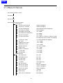
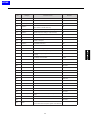
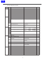
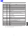
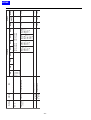
2.1.2 Menu for Service
Key operator operation screen
FAX setting
Special setting
FAX nonvolatile parameter setting
Modem/NCU
V34 send max.bit speed
33600 to 2400[bps]
V34 Rx max. bit speed
33600 to 2400[bps]
V34 max.SYMB speed
3429,3200,3000,2800,2400[baud]
V34 contlrol CH speed
2400,1200[bps]
V34 SYMB criterion(S/N)
-6 to +6[dB]
V34 SYMB select (Distortion)
-6 to +6[dB]
V34 main CH speed
-8 to +7[dB]
V17 send max.speed
V17-14400,V17-12000,V17-9600,V17-7200,
V29-9600,V29-7200,V27-4800,V27-2400[bps]
V17 Rx max. speed
V17-14400,V29-9600,V27-4800[bps]
PIX TxATT
-10 to -15[dB]
TONE/protocol TxATT
-10 to -15[dB]
CED/ANSam TxATT
-10 to -15[dB]
CD/SED ON level
-33,-38,-43,-48[dB]
DTMF TxATT
-6 to -11[dB]
DTMF H-L difference
1 to 4.0[dB]
Tx cable EQL
0,4,8,12[dB]
Rx cable EQL.
0,4,8,12[dB]
Communication
V8 / V34protocol
ON / OFF
Fax KRDS protocol
ON / OFF
V17 EP TONE
ON / OFF
V29 EP TONE
ON / OFF
T1 TIMER
30 to 90[second]
Int'l com function
ON / OFF
V34 Int'l com speed
31200 to 16800[bps]
V17 Int'l com speed
12000 to 7200[bps]
V29 int'l com speed
9600 to 2400[bps]
DIS for Int'l com
1,2[times]
ECM function
ON / OFF
Frame size on ECM send
256,64[bytes]
2-2
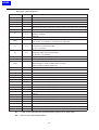
HOME
Coding ability
MH,MH / MR,MH / MR / MMR
ANSam send time
1.0 to 5.5[second]
CED-DIS DELAY TIMER
50 to 150[ms]
DCS-PIX DELAY TIMER
50 to 150[ms]
PIX-PMC DELAY TIMER
50 to 150[ms]
EOL-EOL TIMER
4.0 to 25.5[second]
CFR-PIX WAIT TIMER
6.0 to 25.5[second]
EOM-PIX WAIT TIMER
5.5 to 25.5[second]
JM WAIT TIMER
6.0 to 25.5[second]
V17 selection mode "-"
OFF / ON
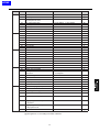
Network
RCV signal detect mode
Number./time
RCV signal detect time
0 to 15[second]
Pause time
1 to 7[second]
Response waiting time
35 to 115[second]
DC-LOOP check
OFF / ON
Busy tone detection
ON / OFF
No. of busy tones
0 to 15[times]
1300 Hz detection
ON / OFF
Pseudo RBT send level
-10 to -15[dBm]
Pseudo RBT cadence
Japan, USA, UK, Germany, None
Min.RING OFF time
100 to 1000[ms]
List output mode
Diag. code journal
OFF / ON
Transmission report
With image / W/O image
Protocol auto print
Only error / OFF / Always
System
Fame erasure HP
5,10,15[mm]
Book mode page order
Tx L to R/Tx R to L
Auto rotation Tx(B5R)
OFF / ON
Auto rotation Tx(LT)
ON / OFF
Auto rotation Tx(A4)
ON / OFF
No. of redials (error)
0 to 7[times]
Error page re-send mode
Error page / All pages
Fax board watch dog
ON / OFF
Original scan mode
Nou standard/Normal
RCV/Print STOP
Valid / Not valid
Report auto output STOP
Valid / Not valid
Fax BOOT rewrite on ISW
OFF / ON
Error code display time
10 to 250sec(10) /Hold
Tx without key counter
Valid / Not valid
Print W/O key counter
Valid / Not valid
Confidential com.
ON / OFF
Relay communication
ON / OFF
2-3
HOME
Closed area RX
ON / OFF
Dial IN function
ON / OFF
Remote RX
ON / OFF
Number display
ON / OFF
Compulsory mem.
ON / OFF
File Re-Tx
ON / OFF
Bundled Tx
ON / OFF
Communication W/O BOX
Normal reception / Communication error
Function parameter
FAX File format
Fax file size
List print
Service-use parameter list
Protocol trace list
TEST
Signal sending test
33600 / 31200 / 28800 / 26400 / 24000 / 21600 /
V34 mainCH.send test
19200 / 16800 / 14400 / 12000 / 9600 / 7200 /
4800 / 2400
V34 mainCH.send test
CTL CH / INFOc / INFOa / Tone B / Tone A
V8 sigl.send test
CM / JM
V17 sigl.send test
14400 / 12000 / 9600 / 7200
V29 sigl.send test
9600 / 7200
V27 ter sigl.send test
4800 / 2400
V21 sigl.send test
-
PB sigl.send test
0 / 1 / 2 / 3 / 4 / 5 / 6 / 7 / 8 / 9 / */ # / A / B / C / D
DP sigl.send test
0/1/2/3/4/5/6/7/8/9
Tone send(Pre-select)
1100 / 1300 / 1650 / 2100 Hz
Tone send(100 HZ step)
PB(High)tone send test
200 to 4000 Hz
PB(Low)tone send test
697 / 770 / 852 / 941 Hz
Pseudo RBT send test
-
1209 / 1336 / 1477 / 1633 Hz
Signal receiving test
V17 sigl.receive test
14400 / 12000 / 9600 / 7200
V29 sigl.receive test
9600 / 7200
V27 ter sigl.receive test
4800 / 2400
V21 sigl.receive test
-
PB sigl.receive test
0/1/2/3/4/5/6/7/8/9/*/#/A/B/C/D
Tone receive Pre-select
1100 / 1300 / 2100 Hz
Hi-Z trans sigl receive
-
2-4
HOME
NCU test
CML relay test
PULSE relay test
EARTH relay test
LOOP relay test
DC-LOOP detect test
Speaker test
Initialization
Abbr entry data
function parameter
Program entry data
Com journal data
Group entry data
F-code Box data
2-5
HOME
2.2 Buzzer Sound
2.2.1 Kinds
Meaning
Kinds of Buzzer Sound
Key receiving sound
End sound
Error sound
Sound Off
A sound made when
a key has been accepted.
A sound made when
an operation has been
normally completed.
Spontaneous
sound off
Spontaneous
sound off
When the cause of the error
is removed, or spontaneous
sound off (FP switching)
A sound made when
an error has occurred.
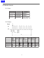
2.2.2 Pattern
Kinds
Key receiving sound
Communication end sound
Communication
error sound
Time
Time of
without
a Single
Sound
Sound
before
and after
Combinations
T1
T0
500ms
Time of
a Single
Sound
T2
Time When
Single
Sounds are
Repeated
T3
(No. of Repetition)
50ms
T4
T5
PiP
1s
500ms
Time of Time When Buzzer
Multiple a Single
sound
Sounds Sound are
Repeated
PiP PiP PiP
4.5s
(five times)
500ms
2-6
Peep
HOME
3
Service Mode
HOME
HOME
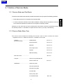
3.1 Outline of Service Mode
3.1.1 Service Mode and Test Mode
The service mode and the test mode are provided in this machine for the purpose of the following operations.
• Initial settings at the time of instllation and rewriting ROM.
• In order to deal with customers' claims after installation, setting status and operations of devices
are checked and operational conditions are changed for analyzing troubles.
Although you can enter both the service mode and the test mode in the same operational method,
this manual provides “4. Test Mode” to explain the test mode for your easy understanding.
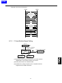
3.1.2 Service Mode Menu Tree
The service mode includes the following three menus, each of which includes sub menus.
Supplement: See “2.1.2 Menu for Services” for details of menu trees.
Function .................................... • Modem/NCU
parameter setting
• Communication
See “3.2.1”.
See “3.2.2”.
• Network
See “3.2.3”.
• List output mode
See “3.2.4”.
• System
See “3.2.5”.
• Machine setting
See “3.2.6”.
FAX File format ........................
See “3.5”.
List print .................................... • Service-use parameter list
• Protocol trace list
See “3.3”.
Initialization .............................. • Abbr entry data
• Function parameter
• Program entry data
• Journal data
• Group entry data
• F-code BOX data
3-1
See “3.6”.
HOME
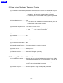
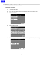
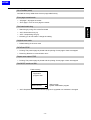
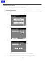
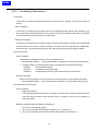
3.1.3 How to Enter the Service Mode
<Operational Procedure>
1.
Turn off the power switch.
2.
While holding down the [HELP] button of the operation panel, turn on the power switch.
3.
Press the [2. FAX] key.
4.
Press the [Special set] key.
5.
Enter the secret password for servicemen (9272) in the box of [PASSWORD] and press [OK].
3-2
HOME
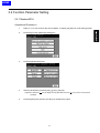
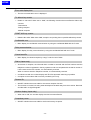
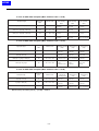
3.2 Function Parameter Setting
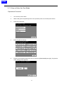
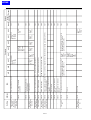
3.2.1 Modem/NCU
<Operational Procedure>
1.
Refer to “3.1.3 How to Enter the Service Mode” to display the [Service mode setting] screen.
2.
Press the [Function parameter setting] key.
3.
Press the [Modem/NCU] key.
4.
Select a parameter by pressing the [ ▲ ] key / [ ▼ ] key.
Supplement: Press the [
] key to display the next parameter. Press the [
parameter.
5.
Press the [EDIT] key until the set value you would like to select.
3-3
] key to return to the previous
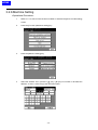
HOME
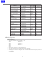
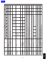
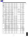
Parameter
Set Value
Factory-shipped
Default Setting
Reference
V34 send max.bit speed
33600to 2400[ bps]
(in steps of 2400)
33600[ bps]
V34 Rx max. bit speed
33600to 2400[ bps]
(in steps of 2400)
33600[ bps]
V34 max.SYMB speed
3429,3200,3000,2800,2400[ baud] 3429[ baud]
Yes
V34 contlrol CH speed
2400,1200[ bps]
1200[ bps]
Yes
V34 SYMB criterion
(S/N)
-6 to +6[ dB]
(in steps of 1dB)
0[ dB]
Yes
V34 SYMB select
(Distortion)
-6 to +6[ dB]
(in steps of 1dB)
0[ dB]
Yes
V34 main CH speed
-8 to +7[ dB]
(in steps of 1dB)
0[ dB]
Yes
V17 send max.speed
V 17- 14400 to V27-2400 [ bps] V 17- 14400[ bps]
V17 Rx max.speed
V 17- 14400 to V27-4800 [ bps] V 17- 14400[ bps]
PIX TxATT
-10 to - 15 [ dBm]
(in steps of 1dBm)
- 10 [ dBm]
Yes
TONE/protocol TxATT
-10 to - 15 [ dBm]
(in steps of 1dBm)
- 10 [ dBm]
Yes
CED/ANSam TxATT
-10 to - 15 [ dBm ]
(in steps of 1dBm)
- 10 [ dBm]
Yes
CD/SED ON level
-33,-38,-43,-48[dBm]
- 48[ dBm]
Yes
DTMF TxATT
–6 to - 11[ dBm]
(in steps of 1dBm)
- 8[ dBm]
DTMF H-L difference
1 to 4.0[dB]
(in steps of 0.5dB 0=0.0dBm)
2.0[ dB]
Tx cable EQL
0,4,8,12[ dB]
0[ dB]
Yes
Rx cable EQL
0,4,8,12[ dB]
0[ dB]
Yes
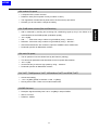
■ Detailed Explanation
Max.SYMB speed
•
Maximum modulation speed (baud rate) of V.34
3429
33.6k to 4.8k
3200
31.2k to 2.4k
3000
28.8k to 2.4k
2800
2400
•
Effective both at the time of sending and receiving
•
The upper limit value of V.34 maximum bit speed is determined.
•
Normally you do not need to change the value. In the case that a V.34 error frequently occurs, set
to SYMB3000.
3-4
HOME
V34 contlrol CH speed
•
A bit speed of the control channel
•
Default is 1200 (The bit speed of many modems is 1200.)
•
The negotiation of 2400/1200 is performed in the V.34 start-up procedure.
•
Normally you do not need to change the setting.
V34 SYMB select criterion(S/N and Distortion)
•
S/N is measured by sending and receiving line conditioning signal (L1/L2) in the Phase 2. Its
result determines the SYMB speed (modulation speed).
•
-6 to +6 [dB]
•
S/N...........It becomes easy to select a high SYMB by using “- direction”.
•
Distortion..It becomes easy to select a high SYMB by using “+ direction”.
•
After S/N and distortion are measured, optimum SYMBOL rate is determined.
•
Parameter peculiar to Matsushita modems
V34 main CH speed
•
The bit speeds of V.34 are determined by the Phase 3 (training).
•
This functional parameter sets thresholds for the bit speed determination.
•
-8 to +7 (dB)
•
It becomes easy to select a high speed by using “- direction”.
•
Parameter peculiar to Matsushita modems
PIX TxATT, TONE/protocol TxATT, CED/ANSam TxATT and DTMF TxATT
•
Outout level setting
•
-10 to -15 [dBm] (DTMF is between -6 and -11 [dBm])
•
Directly sets modem. There are no external attenuator.
CD/SED ON level
•
Reception signal sensitivity level -33 to -48 [dBm] in steps of 5dBm
•
SED is not used.
•
Default is -48dBm.
3-5
HOME
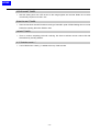
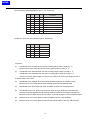
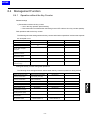
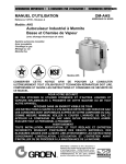
Tx cable EQL and Rx cable EQL
Frequency Response of the Cable Attenuation Equalizer
8
6
Gain (dB)
4
2
0dB
4dB
8dB
12dB
0
-2
-4
-6
-8
0
500
1000
1500
2000
2500
Frequency (Hz)
3-6
3000
3500
4000
HOME
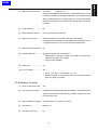
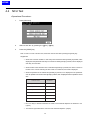
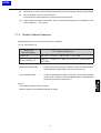
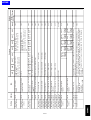
3.2.2 Communication
<Operational Procedure>
1.
Refer to “3.1.3 How to Enter the Service Mode” to indicate the [Service mode setting] screen.
2.
Press the [Function parameter setting] key.
3.
Press the [Communication] key.
4.
Select a parameter by pressing the [▲] key / [▼] key.
Supplement: Press the [
] key to display the next parameter. Press the [
previous parameter.
5.
Press the [EDIT] key until the set value you would like to select.
6.
Press the [BACK] key.
3-7
] key to return to the
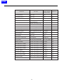
HOME
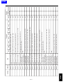
Parameter
Set Value
Factory-shipped
Default Setting
Reference
V8 / V34 protocol
ON / OFF
ON
Fax KRDS protocol
ON / OFF
ON
Yes
V17 EP TONE
ON / OFF
ON
Yes
V29 EP TONE
ON / OFF
OFF
Yes
T1 TIMER
30 to 90[second]
(Set the value in steps of 5s.)
35[sec]
Yes
Int'l com function
ON / OFF
ON
Yes
V34 Int'l com speed
33600 to 16800[bps] (in steps of 2400)
28800[bps]
V17 Int'l com speed
14400 to 7200[bps](in steps of 2400)
7200[bps]
V29 int'l com speed
9600 to 2400[bps](in steps of 2400)
4800[bps]
DIS for Int'lcom
1,2[times]
1[time]
ECM function
ON / OFF
ON
Frame size on ECM send
256,64[bytes]
256[bytes]
Coding ability
MH,MH,/MR,MH/MR/MMR
MH / MR / MMR
Yes
4.0[sec]
Yes
80[ms]
Yes
80[ms]
Yes
80[ms]
Yes
13.0[sec]
Yes
6.0[sec]
Yes
6.0[sec]
Yes
9.0[sec]
Yes
OFF
Yes
JM WAIT TIMER
1.0 to 5.5[second]
(Set the value in steps of 0.5ms.)
50 to 150[ms]
(Set the value in steps of 10ms.)
50 to 150[ms]
(Set the value in steps of 10ms.)
50 to 150[ms]
(Set the value in steps of 10ms.)
4.0 to 25.5[second]
(Set the value in steps of 0.5s.)
6.0 to 25.5[second]
(Set the value in steps of 0.5s.)
5.5 to 25.5[second]
(Set the value in steps of 0.5s.)
6.0 to 25.5[second]
(Set the value in steps of 0.5sec.)
V17 selection mode "-"
ON / OFF
ANSam send time
CED-DIS DELAY TIMER
DCS-PIX DELAY TIMER
PIX-PMC DELAY TIMER
EOL-EOL TIMER
CFR-PIX WAIT TIMER
EOM-PIX WAIT TIMER
3-8
HOME
■ Detailed Explanation
Fax KRDS protocol
•
When set to "ON,"
-
The FAX parameter remote diagnosis along with the copier parameter become possible.
-
File transfer methods in the FAX procedure ((V.34), V.17, V.29, etc.) by using the FAX board,
not the external modem
V.17 EP TONE and V.29 EP TONE
•
Whether the EP tone (Echo Protect: 2100Hz) is added to the top of the training signal.
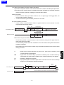
T1 TIMER
•
T1 timer (T.30 standard)
: Calling: designate by the response waiting timer
Called: Starts after DIS is output.
The waiting time until DCS is received.
•
Response waiting timer (55sec)
: Calling : Starts after dialing. Until CED is received.
Int'l com function
•
V.34, V.17 and V.29 International communication mode speed
•
The mode using the number of DIS waiting is turned ON.
•
The international communication mode setting at the time of transmission becomes effective.
Coding ability
•
Effective to both sending and reception.
ANSam send time
•
Determines the ANSam output time of V.8 procedure signal.
•
Normally you do not need to change.
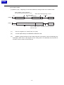
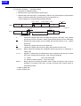
DELAY TIMER
DCS
TCF
PIX
PMC
DIS
CED
PCM : Post Massage Command
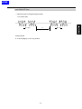
EOL-EOL TIMER
EOL
1 line data
EOL
3-9
1 line data
HOME
CFR-PIX WAIT TIMER
•
Sets the waiting time from CFR is sent to the image signals are received. Radio fax on boats
occasionally requires more the 6 sec.
EOM-PIX WAIT TIMER
•
Some fax machines sends PIX without returing to Phase B in spite of EDM. Waiting time to receive
PIX before sending DIS when EOM is used.
JM WAIT TIMER
•
Time to continue outputting CM until receiving JM. Some machines cannot receive CM with
simultaneously sending ANSam.
V.17 Selection mode “-”
•
V.34 is killed when a dash (-) is added at the top of dial number.
3-10
HOME
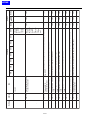
3.2.3 Network
<Operational Procedure>
1.
Refer to “3.1.3 How to Enter the Service Mode” to indicate the [Service mode setting] screen.
2.
Press the [Function parameter setting] key.
3.
Press the [Network] key.
4.
Select a parameter by pressing the [ ▲ ] key / [ ▼ ] key.
Supplement: Press the [
] key to display the next parameter. Press the [
parameter.
5.
Press the [EDIT] key until the set value you would like to select.
6.
Press the [BACK] key.
3-11
] key to return to the previous
HOME
Factory-shipped
Default Setting
Set Value
Parameter
Number / time
RCV signal detect mode
Pause time
0 to 15[second]
(in steps of 1 second)
1 to 7[second]
(in steps of 1 second)
Response waiting time
RCV signal detect time
Number
Reference
Yes
6[sec]
1[sec]
Yes
35 to 115[second]
55[sec]
Yes
DC-LOOP check
ON / OFF
OFF
Yes
Busy tone detection
ON / OFF
ON
Yes
No. of busy tones
0 to 15[times]
(Zero time equals to no detection.)
2
Yes
1300 Hz detection
ON / OFF
ON
Pseudo RBT send level
-10 to -15[dBm]
(in steps of 1dB)
-10[dBm]
Pseudo RBT cadence
None, Japan, USA, UK and German
Japan
min.RING OFF time
100 to 1,000[ms]
200[ms]
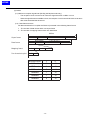
■ Detailed Explanation
RCV signal detect mode
• Sets to “Time” when ninger can not be detected by the number.
Pause time
•
The pause time for one pause key (pause between digits)
Response waiting time
•
Refer to 3.2.2 T1 TIMER section.
DC-LOOP check
•
Checks the DC loop current before dialing.
•
When the current is zero, an error occurs. (T.80, an error code is not displayed.)
•
You can change the setting to be compliant to standards in other countries. In Japan, set this
parameter to OFF.
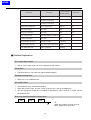
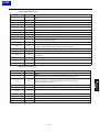
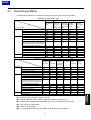
Busy tone detection and No. of busy tones
Toot
Toot
Toot
①
①
3-12
When the number of tones is set to
three, judged to be busy here.
HOME
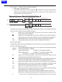
min. RING OFF time
• MInimum time to recognize ringer interval.
For country spec.
a
b
b:Ring-off time
a :To avoid judging “a” as a ring-off time.
3-13
a
HOME
3.2.4 List Output Mode
<Operational Procedure>
1.
Refer to “3.1.3 How to Enter the Service Mode” to indicate the [Service mode setting] screen.
2.
Press the [Function parameter setting] key.
3.
Press the [List output mode] key.
4.
Select a parameter by pressing the [ ▼ ] key / [ ▲ ] key.
Supplement: Press the [
] key to display the next parameter. Press the [
parameter.
5.
Press the [EDIT] key until the set value you would like to select.
6.
Press the [BACK] key.
3-14
] key to return to the previous
HOME
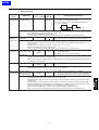
Parameter
Set Value
Factory-shipped
Default Setting
Reference
Diag. Code journal
ON / OFF
OFF
Yes
Transmission report
W/O image / With image
With image
Yes
Protocol auto print
OFF / Always / Only error
OFF
■ Detailed Explanation
Diag. Code journal
When set to “ON,”
- An error code is shown on the communication journal and the screen.
- The diagnosis code is printed on the communication journal.
Transmission report
Even if set to “With image” images are not attached at the time of the quick memory transmission and
the manual transmission.
3-15
HOME
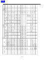
3.2.5 System
<Operational Procedure>
1.
Refer to “3.1.3 How to Enter the Service Mode” to indicate the [Service mode setting] screen.
2.
Press the [Function parameter setting] key.
3.
Press the [System] key.
4.
Select a parameter by pressing the [ ▲ ] key / [ ▼ ] key.
Supplement: Press the [
] key to display the next parameter. Press the [
the previous parameter.
5.
Press the [EDIT] key until the set value you would like to select.
6.
Press the [BACK] key.
3-16
] key to return to
HOME
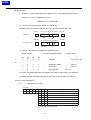
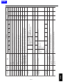
Parameter
Set Value
Factory-shipped
Default Setting
Reference
Fame erasure HP
5,10,15[mm]
5[mm]
Yes
Book mode page order
Tx L to R / Tx R to L
Tx L to R
Yes
Auto rotation Tx(B5R)
ON / OFF
OFF
Yes
Auto rotation Tx(LT)
ON / OFF
ON
Yes
Auto rotation Tx(A4)
ON / OFF
ON
Yes
No. of redials (error)
0 to 7[times]
3
Yes
Error page re-send mode
All pages / Error page
Error page
Yes
Fax board watch dog
ON / OFF
ON
Yes
Original scan mode
Normal / Non standard
Non standard
Yes
RCV/Print STOP
Valid / Not valid
Valid
Yes
Report auto output STOP
Valid / Not valid
Valid
Yes
Fax BOOT rewrite on ISW
ON / OFF
OFF
Yes
Error code display time
Hold / 10 to 250[sec]
(in steps of 10 sec)
20[sec]
Yes
Tx without Key counter
Valid / Not valid
Not valid
Yes
PRINT W/O key counter
Valid / Not valid
Not valid
Yes
Confidential com
ON / OFF
ON
Yes
Relay communication
ON / OFF
ON
Yes
Closed area Rx
ON / OFF
ON
Yes
Dial IN
ON / OFF
ON
Yes
Remote Rx
ON / OFF
ON
Yes
Number display
ON / OFF
ON
Yes
Compulsory mem
ON / OFF
OFF
Yes
File Re-Tx
ON / OFF
ON
Yes
Bundled Tx
ON / OFF
ON
Yes
Communication w/o BOX
Normal / Error
Error
Yes
3-17
HOME
■Detailed Explanation
Frame erasure HP
•
Frame erasure size at scanning
•
Head, bottom, left and right are of the same
•
Erases the outer lines to prevent black lines from appearing. Effective in the book transmission.
Book mode page order
•
Scanning order at transmission.
•
It is required to change the scanning order in the form of a book.
Auto rotation Tx (B5R)
•
“ON”: Transmits B5R in the B4 width.
•
“OFF”: Transmits B5R in the A4 width.
A4
White data
B5
Auto rotation Tx (LT/A4)
•
“ON”: Transmits in the A4 width.
•
“OFF”: Transmits in the A3 width.
3-18
HOME
No. of redials (error)
Counted as a busy redial when the error page redial is busy.
Error page resend mode
•
“All pages”: All pages are resent.
•
“Error page”: From an error page are resent.
Fax board watch dog
•
Watch dog by using CPU of the Fax board
•
“ON”: Reset when hung up.
•
“OFF”: Keeps being hung up.
•
Normally you do not need to change the setting.
Original scan mode
•
Default setting of the user menu
RCV/Print STOP
•
Printing: The present page is printed and the printing of next page or later are stopped.
•
Receiving: Results in communication error.
Report auto output STOP
•
Printing: The present page is printed and the printing of next page or later are stopped.
Fax BOOT rewrite on ISW
Flash memory
Application
program area
ISW program
System initialization program
BOOT BLOCK
•
“ON”: Required when a BOOT BLOCK program is upgraded or a hardware is changed.
3-19
HOME
Error code display time
•
The time communication error is displayed.
Tx without key counter
•
Default is “Not valid.” When set to “Valid,” the following functions become effective without key
counters.
-Transmission
-Polling reception
-Manual reception
PRINT W/O key counter
•
Default is “Not valid.” When set to “Valid,” reception and printing becom possible without key counter.
Confidential com.
•
Menu display for confidential communication by using the confidential BOX with the F-code.
Relay communication
•
Menu display for relay communication by using the confidential BOX with the F-code.
Closed area Rx
•
Menu display for closed reception by using F-code for Junk FAXes.
Dial-in (Japan only)
•
At the time of reception, the informed dial-in number is received and the FAX numbers and the
telephone numbers registered in the key operator mode are compared with the dial-in number. If
it is the same as the FAX number, it is automatically received.
When it conforms with the Telephone number, it is automatically received.
•
Combined use with the number display and TEL/FAX automatic switching is possible.
•
Compliant to the modem dial-in service provided by NTT only.
Remote Rx
•
ON/OFF selection becomes valid for the remote reception function.
•
The function to receive FAX using external telephone located away from the machine. Received
and directed in 2-digit PB signals.
Number display (Japan only)
•
When set to “ON,” the number display function becomes effective.
Compalsory mem.
•
ON/OFF selection becomes valid for the forced memory reception.
3-20
HOME
File Re-Tx (Restored transmmision)
•
ON/OFF selection becomes valid for the restore transmission.
Bundled Tx (Instant batch transmission)
•
ON/OFF selection becomes valid for the instant batch transmission.
Communication W/O BOX
•
An operation is selected at reception before BOX is not appointed.
Ex. Confidential communication documents are received and printed even there is no confidential box.
3-21
HOME
3.2.6 Machine Setting
<Operational Procedure>
1.
Refer to “3.1.3 How to Enter the Service Mode” to indicate the [Service mode setting]
screen.
2.
Press the [Function parameter setting] key.
3.
Press the [Machine setting] key.
4.
Select the address. Then, press the [ ▲ ] key / [ ▼ ] key to increase or decrease the
address, or enter a value using hexa-decimal number.
3-22
HOME
5.
Next, select the data. Then, press the [ ▲ ] key / [ ▼ ] key to increase or decrease the value, or
enter a value using binary numbers.
6.
When the address and the value are correct, press the [confirm] key.
7.
After the settings have been completed, press the [RETURN] key.
Note: Refer to Appendix 2 for the list of address parametors.
3-23
HOME
3.3 List Print
The following lists can be output.
• Service-use parameter list
The setting status of the machine is output.
• Protocol trace list
The facsimile protocol of the communication which was executed previously is output
Supplement: This list can be output from the user mode. This is used to direct users to output the
[Protocol trace list] and perform the FAX communication when users report any
communication errors to the technical support center on the phone, etc.
<Operational Procedure>
1.
Refer to “3.1.3 How to Enter the Service Mode” to indicate the [Service mode setting] screen.
2.
Press the [List print] key.
3.
Press the [Service-use parameter list] key or the [Protocol trace list] key , then press the [PRINT]
key. The selected list is printed.
3-24
HOME
Service-use parameter list example
3-25
HOME
Protocol trace list sample
P1.
Protocol trace list
2000/01/21
26NE00001
TC:13623
System cROM Ver.00 001f 0116 Fax conROM Ver.OA
T
T:CNG
T:CNG
T:CNG
R:ANSam
R:NSF
R:CSI
R:DIS
T:TSI
T:DCS
R:CFR
T:PIX
T:PPS-NULL
R:MCF
T:PIX
T:PPS-MPS
R:MCF
T:PIX
T:PPS-NULL
R:MCF
T:PIX
T:PPS-EOP
R:MCF
T:DCN
FF 03 20 00 00
06 01 02 01 01
FF 03 40 35 38
20 20 20 20 20
FF 13 80 20 EE
FF 03 43 20 20
20 20 20 20 20
FF 13 83 00 82
HR=R8 VR=3.85 MST=0
FF 13 84
V. 34-33600bps
FF 13 BF 00 00
FF 13 8C
V.34-33600bps
FF 13 BF 4F 00
FF 13 8C
V. 34-33600bps
FF 13 BF 00 01
FF 13 8C
V.34-33600bps
FF 13 BF 2F 01
FF 13 8C
FF 13 FB
11
80
00
8A
48
00
55
00
80
80
80
32 39 20
20 20
AA C4 80
20 20 20
20 20
FA 44
OCD=MMR
30
39
20
36
32
34
31
38
.. ......H.U....
.....
..@5829 09 62418
95
20
80
20
80
20
80
20
20
20
20
20
20
... ........
..C
......D
ECM=ON(256)
WD=A3
...
00
FF
.......
...
01
7B
...0..{
...
00
FF
.......
...
01
41
.../..A
...
...
3-26
HOME
3.4 FAX Counter on the Machine Management List
Refer to the service handbook of the Copier for the output procedure (36 modes).
3-27
HOME
3.5 FAX File Format
• Fax memory size and format in the E-RDH memory
<Operational Procedure>
1.
Refer to “3.1.3 How to Enter the Service Mode” to indicate the [Service mode setting] screen.
2.
Press the [FAX File format] key.
3.
Select the Fax file size and press [Format] key.
4.
In case of file format, press the [YES] key.
•
When the format is executed and completed, the system is restarted.
•
Keep in mind that all files (files for sending / files for printing) are erased.
3-28
HOME
3.6 Initialization
The following data can be initialized. Select data you would like to initialize and press the [OK] key.
• Abbr entry data ......................... All abbreviated dial data is deleted.
• Function parameter ................... Function settings are initialized to the factory-shipped settings.
• Program entry data ................... All program dial registration data is deleted.
• Com journal data ...................... All communication journal data is deleted.
• Group entry data ....................... All group dial registration data is deleted.
• F-code BOX data ...................... All F-code BOX data is deleted.
<Operational Procedure>
1.
Refer to “3.1.3 How to Enter the Service Mode” to indicate the [Service mode setting] screen.
2.
Press the [Initialization] key.
3.
Select the category of data you would like to initialize and press the [OK] key.
Supplement: More than one item can be selected.
3-29
HOME
4.
Confirm the shown data category and press the [YES] key.
The selected data is initialized.
3-30
HOME
4
Test Mode
HOME
HOME
4.1 Outline of the Test Mode
4.1.1 Service Mode and Test Mode
The service mode and the test mode are provided in this machine for the purpose of the following
operation.
• In order to deal with customers' claims after installation, setting status and operations of devices
are checked and operational conditions are changed for analyzing troubles.
Although you can enter both the service mode and the test mode in the same operational procedure,
this manual provides “3. Service Mode” to explain the service mode for your easy understanding.
4.1.2 Test Mode Menu Tree
The test mode include the following three menus, each of which includes sub menus.
Supplement: See “2.2.2 Menu for Services” for details of menu trees.
• Signal sending test
• Signal receiving test
• NCU test
4-1
HOME
4.1.3 How to Enter the Test Mode
“Operational Procedure”
1.
Turn OFF the power switch.
2.
While holding down the [HELP] button of the operation panel, turn ON the power switch.
3.
Press the [2. FAX] key.
4.
Press the [Special set] key.
5.
Enter the secret password (9272) for service in the box of [PASSWORD],then [OK]. The [Service
mode setting] screen appears.
4-2
HOME
6.
Press the [TEST] key.
4-3
HOME
4.2 Signal Sending Test
Image information signals, control signals and DTMF can be individually output. Additionally, signal
sounds can be monitored by monitor speaker.
<Operational Procedure>
1.
Press [Signal sending test].
2.
Select a test item by pressing the [▲] key / [▼] key.
Supplement: Press the [
] key to display the next test item. Press the [
] key to return to the
previous test item.
3.
Press the [EDIT] key to select the parameter you would like to test.
4.
Press the [START] key.
Note: In order to move to another test, select the next test item after pressing the [Stop] key.
4-4
HOME
Factory-shipped
Default Setting
Parameter
Contents of Test
V34 main CH send test
33600 / 31200 / 28800 / 26400 /
24000 / 21600 / 19200 / 16800 /
33600[ bps]
14400 / 12000 / 9600 / 7200 /
4800 / 2400[ bps]
V34 contorl CH sigl.send
CTL CH / I NFOc / I NFOa /
ToneB /ToneA
CTL CH
V8 sigl.send test
CM / JM
CM
V17 sigl.send test
14400 / 12000 / 9600 /
7200[ bps]
14400[ bps]
V29 sigl.send test
9600 / 7200[ bps]
9600[ bps]
V27 ter sigl.send test
4800 / 2400[ bps]
4800[ bps]
V21 sigl.send test
-
-
PB sigl.send test
0/1/2/3/4/5/6/7/8/9/
0
* /#/A /B/C/D
DP sigl.send test
0/1/2/3/4/5/6/7/8/9
0
Tone send(Pre-select)
1100 / 1300 / 1650 / 2100 [ Hz]
1650[ Hz]
Tone send(100 HZ step)
200 to4000[ Hz] (In steps of 100Hz) 200[ Hz]
PB(High)tone send test
1209 / 1336 / 1477 / 1633 [ Hz]
1477[ Hz]
PB(Low)tone send test
697 / 770 / 852 / 941[ Hz]
697[ Hz]
Pseudo RBT send test
-
-
■ Detailed Explanation
Signal sending test
Signal is output from pressing [START] to pressing [STOP].
4-5
HOME
4.3 Signal Receiving Test
Two machines are used for this test. Signal sounds can be monitored by using the monitor speaker.
<Operational Procedure>
1.
Press [Signal receiving test].
2.
Select a test item by pressing the [▲] key / [▼] key.
3.
Press the [EDIT] key to select the parameter you would like to test.
4.
Press the [START] key.
Note: In order to move to another test, select the next test item after pressing the [STOP] key.
Factory-shipped
Default Setting
Parameter
Contents of Test
V17 sigl .receive
14400 / 12000 / 9600 /
7200[ bps]
14400[ bps]
V29 sigl. receive
9600 / 7200[ bps]
9600[ bps]
V27 ter sigl .receive
4800 / 2400[ bps]
4800[ bps]
V21 sigl. receive
-
-
PB sigl.receive
0/1/2/3/4/5/6/7/8/9/
0
* /#/A /B/C/D
Tone receive(Pre-select)
1100 / 1300 / 2100
1100[ Hz]
Hi-Z trans sigl receive
-
-
Supplement: The status of testing or results of tests are shown in the title line as follows
RCV
: Waiting signals
OK/NG: Results of signal reception
4-6
HOME
■ Detailed Explanation
Hi-Z trans sigl receive
1100Hz only (No 1300Hz)
NOTE: The receiving test does not include the V.34 signal.
4-7
HOME
4.4 NCU Test
<Operational Procedure>
1.
Press [NCU test].
2.
Select a test item by pressing the [▲] key / [▼] key.
3.
Press the [START] key.
Note: In order to move to another test, select the next test item after pressing the [STOP] key.
Supplement:
•
When CML / PULSE / EARTH / LOOP relay test is selected and the [START] is pressed, ON is
displayed in the parameter and relay is turned to ON. When [STOP] is pressed, OFF is displayed
and relay is turned OFF.
•
When the DC-LOOP detection test is selected and [START] is pressed, DT=0001 is shown in
the title row in case of detecting the DC-LOOP. If not detected, DT=0000 is displayed.
•
When the speaker test is selected and [START] is pressed, On is displayed in the parameter
and the speaker is turned ON. When [STOP] is pressed, OFF is displayed and the speaker is turned
OFF.
Relay to
Be Tested
Contents of Test
CML relay test
RL1
PULSE relay test
RL5
EARTH relay test
RL4
LOOP relay test
RL3
CD-LOOP detect test
Speaker test
•
RL4 is a relay to determine whether DC-LOOP of the external telephone is detected or not.
(Japan)
•
The XDCLP signal detects the off-hook of the external telephone. (Japan)
4-8
HOME
■ Detailed Explanation
DC-LOOP detect test
DT=0001
Shown at the upper-right corner.
Indicates four ports.(NOTE). “1”:ON
“0”:OFF
4-9
HOME
4-10
HOME
5
Troubleshooting
HOME
HOME
5.1 Error Codes
Code
No.
F86-00
Category
Contents of Error
System and soft error
Remarks
Not used
F86-01
Not used
F86-02
Checksum error
F error (total control)
F86-03
Hard error
F error (total control)
F86-04
Interface error
F error (total control)
F86-05
Not used
F86-06
Not used
F86-07
Not used
F86-08
Not used
F86-09
Not used
E86-10
Not used
E86-11
Not used
E86-12
Not used
E86-13
Not used
E86-14
Not used
E86-15
Not used
E86-16
Not used
E86-17
Not used
E86-18
Not used
E86-19
Not used
E86-20
JC soft error
JC
E86-21
Not used
E86-22
Device error (GA LOCAL SRAM)
JC
(only at the test mode)
E86-23
Device error (DRAM)
JC
(only at the test mode)
E86-24
Not used
E86-25
Device error (GA)
JC
(only at the test mode)
E86-26
Timeout error due to no responses from DC at the
time of a break process
JC
E86-27
Timeout error due to no responses from DC at the
time of a break process
JC
E86-28
Timeout error due to no responses from DC at the
time of a break process
JC
E86-29
E86-30
Not used
MIF driver error
Driver soft error
MIF
E86-31
MIF driver error
Error of the receiving frame length from the main
side
MIF
E86-32
MIF driver error
Error of the receiving frame header from the main
side
MIF
5-1
HOME
Code
No.
Category
E86-33
MIF driver error
232C I/F sequence error
MIF
E86-34
MIF driver error
DPRAM I/F sequence error
MIF
E86-35
MIF driver error
DPRAM CTL/STS register abnormality
MIF
E86-36
MIF driver error
ACK waiting timeout
MIF
E86-37
MIF driver error
DPRAM RESET reception
MIF
Contents of Error
Remarks
E86-38
Not used
E86-39
Not used
E86-40
MIF soft error
MSG I/F error with JC
MIF
E86-41
MIF soft error
I/F error with driver
MIF
E86-42
I/F error with main
Undefined command reception
M IF
E86-43
I/F error with main
Command frame length error
MIF
E86-44
I/F error with main
Command parameter length error
M IF
E86-45
I/F error with main
Undefined parameter
MIF
E86-46
I/F error with main
Command/response sequence error
MIF
E86-47
Not used
E86-48
Not used
E86-49
Not used
E86-50
Not used
E86-51
Not used
E86-52
Not used
E86-53
Not used
E86-54
Not used
E86-55
Not used
E86-56
Not used
E86-57
Not used
E86-58
Not used
E86-59
Not used
E86-60
Not used
E86-61
Not used
E86-62
Not used
E86-63
Not used
E86-64
Not used
E86-65
Not used
E86-66
Not used
5-2
HOME
Code
No.
Category
Contents of Error
Remarks
E86-67
Not used
E86-68
Not used
E86-69
Not used
E86-70
Not used
E86-71
Not used
E86-72
Not used
E86-73
Not used
E86-74
Not used
E86-75
Not used
E86-76
Not used
E86-77
Not used
E86-78
Not used
E86-79
Not used
E86-80
Not used
E86-81
Not used
E86-82
Not used
E86-83
Not used
E86-84
Not used
E86-85
Insufficient control memory (for communication job)
Total control
E86-86
Insufficient control memory (for print memory)
Total control
E86-87
Insufficient control memory (for scan memory)
Total control
E86-88
Quick sending image object abnormality
Total control
E86-89
FAX board response waiting timeout
Total control
E86-90
File system error
A file system error occurred in the initial condition,
but returned to the normal condition by initializing
the file.
Total control
E86-91
File system error
File access error (for UI)
Total control
E86-92
File system error
File access error (for job management)
Total control
E86-93
File system error
File access error (for communication job)
Total control
E86-94
File system error
File access error
(for communication job and file node /pipe)
Total control
E86-95
File system error
File access error (for print memory)
Total control
E86-96
File system error
File access error
(for print memory and file node /pipe)
Total control
E86-97
File system error
File access error (for scan memory)
Total control
E86-98
File system error
File access error
(for scan memory and file node /pipe)
Total control
E86-99
File system error
Reservation
5-3
HOME
Code
No.
Category
Contents of Error
Remarks
Sending
Waiting for a response of a remote station (35second) T1 timeout
T01
Sending
T1 over after the mode has been changed
(35 seconds)
T02
Sending
DCN reception in DIS waiting
T03
Sending
Unexpected command reception in DIS waiting
T00
T1 timeout
T04
Reserved
T05
Reserved
T06
Sending
DCN reception in CFR /FTT waiting
T07
Not used
T08
Sending
Training failure at 2400bps
T09
Sending
No response to DCS
T10
Reserved
T11
Sending
DCN reception while waiting for post message
responses
T12
Sending
Unexpected command reception while waiting for
post message responses
T13
Sending
No response while waiting for post message
responses
T14
T15
Not used
ECM sending
Reserved
T16
Reserved
T17
Reserved
T18
Sending
No reception ability in a remote station
T19
Not used
T20
Reserved
T21
Reserved
T22
Reserved
T23
Reserved
T24
Reserved
T25
Reserved
T26
Reserved
T27
Reserved
T28
ECM sending
Timeout by RR/RNR (60 seconds)
T5 timeout
T29
Not used
T30
Not used
T31
Not used
T32
ECM sending
Fall back over by CTC
T33
Not used
T34
Not used
5-4
HOME
Code
No.
Category
Contents of Error
T35
ECM transmission
No responses to RR
T36
ECM transmission
DCN reception to RR
T37
Polling transmission
T38
F code polling tx
Not used
SID is received when SEP is received
T39
T40
Remarks
CC
Reserved
Calling
Software error at calling
T41
Not used
T42
Sending
RTN/PIN reception
T43
Sending
Three continuous CRP signal reception
T44
Sending
Time error between frames at transmission
T45
Reserved
T46
Reserved
T47
Reserved
T48
Not used
T49
Not used
T50
FAX-KRDS
Host terminal ID inconsistency
S-5C
T51
Not used
T52
Reserved
T53
Reserved
T54
Not used
T55
Not used
T56
BFT transmission
Reserved
T57
BFT transmission
Reserved
T58
Polling transmission
Calling by polling reception, but a remote station
does not have polling documents
T59
T60
Reserved
Polling transmission
Received the polling transmission request (DTC),
but there are no polling transmission documents
T61
Reserved
T62
Polling transmission
T63
Polling transmission
Box number specified by SEP is not valid.
T64
T65
CC
Reserved
Reserved
Polling transmission
Reserved
T66
Reserved
T67
Reserved
T68
SEP polling
Reserved
T69
SUB transmission
Reserved
5-5
HOME
Code
No.
Category
Contents of Error
Remarks
T70
Reserved
T71
Reserved
T72
Not used
T73
Transmission
Modem response waiting T.0 (60 seconds)
CC
T74
V34
No changes in the V 34 modem status
CC
T75
V34
V34 signal sending error
CC
T76
V34
CS2 is not turned to O N
CC
T77
Transmission
DC middle ware error
DC
T78
Transmission
DC soft ware error
DC
T79
Transmission
JC soft error at transmission
IC
T80
Call control
LOOP current detection NG when CML is turned ON
at calling
T81
Call control
Dial Tone detection NG when CML is turned ON at
calling
T82
Call control
Answer tone (CED/DIS) waiting timeout after dialing
at calling
T83
Call control
Busy tone detection at calling
T84
Call control
Line dial error
T85
Call control
Short disconnection was detected after LOOP
current detection at calling
T86
Call control
Dial Tone continues after dialing
T87
Not used
T88
Not used
T89
Not used
T90
Not used
T91
Not used
T92
Not used
T93
Not used
T94
Not used
T95
Call control
When called, short disconnection of LOOP current
was detected during a call
T96
Not used
T97
Not used
T98
Not used
T99
Call control
Remote stations number is deleted while waiting for
Generation on the whole
abbreviated or one-touch re-dialing
control side
(redial / transmission / polling reception)
5-6
HOME
Code
No.
Category
Contents of Error
R00
Reception
DCS was not received within 35 seconds (T1 over)
R01
Reception
T1 timeout after EOM sending
R02
Reception
DCN reception in DCS waiting
R03
Reception
Unexpected command reception in DCS waiting
R04
Reception
FIF error of DCS
R05
Remarks
Reserved
R06
Reception
Reserved
R07
Reception
Image information does not come in image
information waiting
R08
Reception
CD OFF while receiving image information
R09
Reception
DCN reception in post message waiting
R10
Reception
Unexpected command reception in post message
waiting
R11
Reception
Command was not received which waiting for post
message
R12
Reception
Timeout during EOL-EOL
R13
Reserved
R14
Reserved
R15
Reserved
R16
Reserved
R17
Reserved
R18
Not used
R19
Reception
Reserved
R20
CUG reception
Reserved
R21
CUG reception
Reserved
R22
CUG reception
Reserved
R23
Reserved
R24
ECM reception
RR-RNR repeats for 2 minutes
R25
ECM reception
Command was not received while waiting for
responses to RNR
R26
ECM reception
Unexpected command was received while waiting
for responses to RNR
R27
ECM reception
DCN reception while waiting for responses to RNR
R28
ECM reception
R29
ECM reception
Reserved
Timeout (35 seconds) between frames occurred
R30
Reserved
R31
Reserved
R32
Not used
R33
Reception
DIS reception to DTC (German specifications only)
5-7
HOME
Code
No.
Category
Contents of Error
Remarks
F code confidential
reception
PWD was received when SUB was received.
CC
R37
V 34
CS2 is not turned to ON.
CC
R38
V 34
No change in V 34 modem and status
CC
R34
R35
R36
R39
R40
Not used
When received
Soft error when called
CC
R41
Not used
R42
Not used
R43
Not used
R44
Not used
R45
Reception
R46
Reception
Phase C timeout (NonECM reception only)
Reserved
R47
Not used
R48
Reception
Not used
R49
Reception
DCN reception while waiting for image information
R50
Reception
No. of error lines exceeds.
R51
Reception
Reserved
R52
Reception
Reserved
R53
Reception
Reserved
R54
Reception
Reserved
R55
Remote OMR
Reserved
R56
Reception
Reserved
R57
Remote diagnosis
Reserved
R58
Remote diagnosis
Reserved
R59
Remote diagnosis
Reserved
R60
Reception
R61
Reception
Not used
R62
Reception
Not used
R63
Reception
R64
Reception
Not used
R65
Reception
Not used
R66
SEP polling
SEP polling transmission request was received
without SEP polling transmission ability
CC
R67
SUB reception
SUB was directed without SUB reception ability
CC
DC
Reception image error (RTN/PIN sending)
Three continuous CRP signal reception
5-8
HOME
Code
No.
Category
Contents of Error
R68
Remarks
Not used
R69
ECM reception
Communications are cut when EOR is received.
CC
R70
ECM reception
Decode error occured in ECM
DC
R71
Reception
RTC detection error
(No. of EOL is smaller than FP.)
DC
R72
Reception
Received documents of 840mm or larger
DC
R73
Reception
Modem response waiting T.0 (60 seconds)
DC
R74
Reception
Reception byte size error
Not used
R75
V 34
V 34 signal sending error
R76
V 34
Unexpected command was received in V.34 mode
phase C reception
R77
Reception
DC middle ware error
DC
R78
Reception
DC software error
DC
R79
Reception
JC soft error during reception
JC
R80
FAX-KRDS
Serial No. inconsistency at reception from a host
S-JC
R81
FAX-KRDS
Line was cut by writing direction from a host during
copying
S-JC
R82
FAX-KRDS
Line was cut by receiving FAX-KRDS direction due
to inability of FAX-KRDS
S-JC
R83
FAX-KRDS
Unauthorized command from a host
S-JC
R84
FAX-KRDS
Writing error to nonvolatile
R85
Not used
R86
Not used
R87
Not used
R88
Not used
R89
Not used
R90
Reserved
R91
Reserved
R92
Reserved
R93
Not used
R94
Not used
R95
Not used
R96
F-code reception
Confidential box number specified by SUB is not
valid.
R97
Not used
R98
Not used
R99
Others
Reception command was received from the whole
control side before reception signals were detected.
5-9
HOME
5.2 Diagnostic Codes
5.2.1
Outline
The diagnostic code is a 17-digit hexadecimal code indicating a communication conditions and
status.
The diagnostic code is printed on the communication journal.
The purpose of the diagnostic code is to obtain detailed information of communication results
and conditions so as to analyze communication troubles.
5.2.2
Explanation
XX XX XX XX XX XX XX XX XX XX XX XX XX XX XX XX XX XX XX
(1) (2) (3) (4) (5) (6) (7) (8) (9) (10) (11) (12) (13) (14) (15) (16) (17) (18) (19)
(1)
Types of call out / called
(2)
Types of sending and receiving
(3)
Application sending mode
(4)
One-time communication parameter
(5)
Box No.(Upper digits)
(6)
Box No.(Lower digits)
(7)
Horizontal RES
(8)
Vertical RES
(9)
Coding
(10)
Document width
(11)
Document length
(12)
Communication speed (SPEED0)
(13)
Communication speed (SPEED1)
5-10
HOME
(14)
Communication speed (SPEED2)
(15)
Communication speed (SPEED3)
(16)
MSLT
(17)
ECM / PIX / BFT protocol command
(18)
Remote station coding ability
(19)
Remote station ECM/PIX/BFT protocol ability
5-11
HOME
(1) Types of call out / called
bit7:
F network called (Japan)
bit6:
PSTN called
bit5:
Dial-in (Japan)
bit4:
Telephone
bit3:
Group
bit2:
One-touch dialing
bit1:
Abbreviated dialing
bit0:
Key pad dialing
(2) Types of sending and receiving
bit7:
Sending
bit6:
Error page resending
bit5:
Forwarding transmission
bit4:
Polled transmission
bit3:
Receiving
bit2:
Recovery transmission
bit1:
Called turnaround
bit0:
Polling Rx
(3) Application transmission mode
bit7:
Mixed size transmission
bit6:
Fame erasure transmission
bit5:
Book mode transmission
bit4:
2-in-1 transmission
bit3:
Original size appointing Tx
5-12
HOME
bit2:
Upside down
bit1:
Special scanning (non standerd, Z fold, Long original)
bit0:
(Not used)
(4) One-time communication parameter
bit7:
Timer Tx
bit6:
(Not used)
bit5:
KRDS
bit4:
PC-Fax transmission (Rx/V2)
bit3:
V34 appoint transmission
bit2:
F-code transmission
bit1:
ECM transmission
bit0:
International mode transmission
(5) Box No. (Upper digits)
bit7:
(Not used)
bit6:
(Not used)
bit5:
(Not used)
bit4:
(Not used)
bit3-bit0:
1-20, 100-104, 999 Upper (Hex)
(6) Box No. (Lower digits)
bit7-bit0:
1-20, 100-104, 999 Lower (Hex).
(7) Horizontal RES
bit7:
400dpi
bit6:
300dpi
bit5:
200dpi
5-13
HOME
bit4:
(Not used)
bit3:
16 pels/mm
bit2:
(Not used)
bit1:
8 pels/mm
bit0:
(Not used)
(8) Vertical RES
bit7:
400dpi
bit6:
300dpi
bit5:
200dpi
bit4:
100dpi
bit3:
15.4 1/mm
bit2:
(Not used)
bit1:
7.7 1/mm
bit0:
3.85 1/mm
(9) Coding
bit7:
(Not used)
bit6:
(Not used)
bit5:
(JPEG)
bit4:
(JBIG)
bit3:
MMR
bit2:
MR
bit1:
MH
bit0:
THRU
5-14
HOME
(10) Document width
bit7:
(Not used)
bit6:
(Not used)
bit5:
(Legal)
bit4:
(Letter )
bit3:
A3
bit2:
B4
bit1:
A4
bit0:
(Not used)
(11) Document length
bit7:
(Not used)
bit6:
No limits
bit5:
(Legal)
bit4:
(Letter)
bit3:
(Not used)
bit2:
B4
bit1:
A4
bit0:
(Not used)
(12) Communication speed (SPEED0)
bit7:
(Not used)
bit6:
(Not used)
bit5:
(Not used)
bit4:
V29-96
bit3:
V29-72
5-15
HOME
bit2:
(Not used)
bit1:
V27-48
bit0:
V27-24
(13) Communication speed (SPEED1)
bit7:
V17-144
bit6:
V17-120
bit5:
V17-96
bit4:
V17-72
bit3:
(V33-144)
bit2:
(V33-120)
bit1:
(V33-96)
bit0:
(V33-72)
(14) Communication speed (SPEED2)
bit7:
V34-192
bit6:
V34-168
bit5:
V34-144
bit4:
V34-120
bit3:
V34-96
bit2:
V34-72
bit1:
V34-48
bit0:
V34-24
(15) Communication speed (SPEED3)
bit7:
(Not used)
bit6:
(Not used)
5-16
HOME
bit5:
V34-336
bit4:
V34-312
bit3:
V34-288
bit2:
V34-264
bit1:
V34-240
bit0:
V34-216
(16) MSLT
bit7:
(Not used)
bit6:
(Not used)
bit5:
(Not used)
bit4:
(Not used)
bit3 to bit0: MSLT of resolution shown as Vers
(17) ECM / PIX / BFT protocol
bit7:
ECM frame size 0: 256/ 1: 64
bit6:
ECM
bit5:
DIAG (KRDS)
bit4:
(BFT)
bit3:
(BTM)
bit2:
SID
bit1:
SEP
bit0:
SUB
(18) Remote station coding ability
bit7:
(Not used)
bit6:
(Not used)
bit5:
(JPEG)
5-17
HOME
bit4:
(JBIG)
bit3:
MMR
bit2:
MR
bit1:
MH
bit0:
THRU
(19)Remote station ECM/PIX/BFT protocol
bit7:
(Not used)
bit6:
ECM
bit5:
DIAG (KRDS)bit4: (BFT)
bit3:
(BTM)
bit2:
SID
bit1:
SEP
bit0:
SUB
Supplement: (Not used) bit is set to 0.
5-18
HOME
5.3 FAX Board Hardware Self-diagnosis
SRAM / Local SRAM for GA / SDRAM / GA / modem are checked.
(1)
Memory check
•
Memory is written, read and verified. If no abnormality is found, it is cleared to 0.
•
Memory is written, read and verified twice. First, it is checked in AA55 data and then
checked in BNT reverse data (55AA).
(2)
GA check
•
The test pattern is in ROM. Whether the result conforms or not is judged by the reduction
rate of 50% (Src:32H-WORD and Dst: 16H-WORD).
(3)
Modem check
•
The modem is initialized to check whether it has been completed normally.
With the FK-101 cover removed, the error status of each device is displayed in LED as follows:
LED
STATUS
LED DISPLAY
LED3
LED2
LED1
REMARKS
All LEDs are turned off
CPU or ROM malfunctions.
LED 1 is turned on
SRAM malfunctions.
LED 3 is turned on
LSRAM malfunctions.
LED1 and 2 are turned on
SDRAM malfunctions.
LED 1 and 3 are turned on
GA malfunctions.
LED 2 and 3 are turned on
A modem malfunctions.
LED 1, 2 and 3 are turned on
All devices OK.
:light on
:light off
5-19
HOME
5.4 Countermeasures in Case of No Error Codes
When no error codes are founds, take the following countermeasures.
(1)
When the FK-101 main body is required to be replaced, refer to “6.1 FK-101 Body and Related
Items” for replacement.
• Replacement of battery.
• Replacement of control board.
• Replacement of NCU board.
(2)
When the one-touch button or speaker is required to be replaced, refer to “ 6.2 One-touch
Button and Speaker” for replacement.
• Replacement of one-touch button.
• Replacement of speaker.
5-20
HOME
6
Replacement Procedure
HOME
HOME
6.1 FK-101 Body and Related Items
6.1.1 Removal of the FK-101 Body
In order to replace each part of the FK-101, remove the FK-101 body in the following order.
1.
Remove four screws of the FK-101 from the back side of the body.
2.
Pull the FK-101 body toward you, paying attention to the connector at the upper FK-101 body.
[NOTE] Gently pull the FK101 from the upper part, taking care not to damage the connector.
Connector
6-1
HOME
3.
Remove the cover of the FK-101 body. (12 screws)
4.
The following parts are seen when the cover is removed.
[NOTE] Since the board may be damaged due to static electricity, take a measure against static electricity
before replacement.
FAX control board
NCU board
Battery
Supplement: There are two kinds of telephone jacks.(country spec)
5.
After the replacements, attach the FK-101 body to the machine in the reverse order of the above.
6-2
HOME
6.1.2 Replacement of Battery
[NOTE] Since the board may be damaged due to static electricity, take a measure against static electricity
before replacement. The battery has a charging life of 5000 times, replacement is assumed to
be unnecessary.
1.
Remove the connector which is connected to the battery.
Connector
Battery
Sponge
FAX control board
2.
Since the buttery is fixed to the FAX control board by using the double-sided tape and a sponge,
replace batteries, taking care of the FAX control board.
3.
Connect the connector in the reverse order of the above.
6-3
HOME
6.1.3 Replacement of the FAX Control Board
[NOTE] Since the board may be damaged due to static electricity, take a measure against static electricity
before replacement.
Since the FAX control board is connected to the NCU board below with a connector, take care
not to damage the connector when you remove the board.
1.
Remove the FAX control board. (8 screws)
Connector
FAX control board
NCU board
2.
Attach a new FAX control board in the reverse order of the above.
6-4
HOME
6.1.4 Replacement of the NCU Board
[NOTE] Since the board may be damaged due to static electricity, take a measure against static electricity
before replacement.
Since it is required first to remove the FAX control board for replacement of the NCU board,
refer to 6.1.3 and remove the FAX control board, taking care of the connector.
Replace the NCU board, taking care not to damage the external I/O adapter which is directly
attached to the NCU board.
1.
Remove the FAX control board. (5 screw)
NCU board
External I/O adapter
2.
Attach a new NCU board in the reverse order of the above.
6-5
HOME
6.2 One-touch Program Key and Speaker
6.2.1 Replacement of One-touch Program Key
1.
As shown below, insert a steel scale, etc. in the clearance at the lower right corner of the
one-touch program key and move the hook which fixes the one-touch program key to the
right a little with the scale, raise the scale, to remove the one-touch program key.
Steel Scale, etc.
Clearance
Hook
Steel Scale, etc.
6-6
HOME
2.
Connect the connector to the new one-touch program key as follows:
One-touch program key
Connector
3.
Attach a one-touch program key
6.2.2 Replacement of the Speaker
[NOTE] It is required to remove the one-touch program key first for the replacement of the speaker.
Refer to 6.2.1 and remove the one-touch program key first.
1.
Remove the one-touch program key.
2.
Replace the speakers as indicated in the following picture.(two screws and a connector (with
an adapter on the speaker side))
Speaker
Connector
Adapter
3.
Attach a speaker in the reverse order of the above.
6-7
HOME
6-8
HOME
7
Communication Control
HOME
HOME
7.1 Protocol
7.1.1
FIF bits of DIS, DTC and DCS
FIF Data Configuration List (DIS/DTC)
octet
4
5
bit
Function
Contents
Default
1
Reserved
0
2
Reserved
0
3
Reserved
0
4
Reserved
0
5
Reserved
0
6
V.8 ability
0
7
ECM frame
8
Reserved
0: 256 octet 1: 64 octet
0
9
Ready for Polled transmission
1: polled transmission
documents exist
0: no polled transmission
documents
@
10
Receiver ability
1: Reception is possible.
0: Reception is impossible.
@
11
Transmission speed ability
Refer to *1.
1
0
12
1
13
0
14
6
1
15
R8*7.71/mm or
200*200 pels/25.4mm
1: 7.71/mm
0: 3.851/mm
1
16
Two-dimensional coding ability
1: MR 0: MH
1
17
Recording paper width ability
bit
(17, 18)
0, 0=A4
1, 0=B4
0, 1=A3
1, 1=Invalid
0
Recording paper length ability
bit 0, 1=
(19, 20)
0, 0=A4
1, 0=B4
Unlimited
1, 1=Invalid
0
Minimum scan line time ability
Refer to *2.
18
19
20
21
22
7
0
Expansion field
1
25
Reserved
0
26
Non-compression mode
0
27
Error correction mode (ECM) ability
28
29
8
1
1
0
23
24
1
1: with ECM 0: without ECM
1
0: fixed
0
Reserved
30
Reserved
31
T.6 coding (MMR) ability
0
0
1: with MMR 0: without MMR
1
32
Expansion field
1
33
Reserved
0
34
Reserved
0
35
Reserved
0
36
Reserved
0
37
Reserved
0
38
Reserved
0
39
Reserved
0
40
Expansion field
1
7-1
HOME
octet
9
10
11
12
13
bit
Function
Contents
Default
KX
1
1
41
42
R8*15.41/mm
300*300pels/25.4mm
43
R16*15.41/mm or
400*400pels/25.4mm
1
44
45
inch ability
mm ability
1
1
46
Minimum scan line time ability of
high resolution
47
48
49
50
Selective polling
Expansion field
Sub address ability
Password
1
1
1
1
51
Ready for data file transmission
(polling)
0
52
53
54
55
56
57
58
Reserved
BFT transfer ability
DTM transfer ability
EDI transfer ability
Expansion field
BTM transfer ability
Reserved
0
1
0
0
0
0
0
59
Character or mixed mode
documents ready for Tx (polling)
0
60
61
62
63
64
65
66
67
68
69
70
71
72
73
74
75
Character mode ability
Reserved
Mixed mode ability
Reserved
Expansion field
Processible mode (T.505)
Digital network ability
Full-duplex communication ability
JPEG coding ability
Full color mode
0
0
0
0
0
0
0
0
0
0
0
0
0
0
0
0
0: T15.4=T7.7
1: T15.4=1/2T7.7
0: Half-duplex 1: Full-duplex
0 Fixed
12 bits / pixel component
Expansion field
No sub sampling (1:1:1)
Custom illuminant
Custom gamut range
0
76
North America Letter (215.9*279.4)
ability
0
77
North America Legal (215.9*355.6)
ability
0
78
Single progression sequential coding
(T.85) basic ability
0
79
Single progression sequential coding
(T.85) optional LO ability
0
80
Expansion field
0
@) Changes to 0 or 1 according to a status of devices.
7-2
HOME
*1) Transmission speed ability (bit 11, 12, 13 and 14)
11
12
13
14
0
0
1
1
1
0
1
0
1
1
0
0
0
0
0
0
0
0
0
1
Contents
Transmission speed
V27ter f al l back mode
V 27ter
V29
V27ter& V 29
V 27ter& V 29& V17
24
48,24
96,72
96,72,48,24
144,120,96,72,48,24
*2) Minimum scan line time ability (bit 21, 22 and 23)
21
22
23
0
0
0
0
1
1
1
1
0
0
1
1
0
0
1
1
0
1
0
1
0
1
0
1
Contents
3.851/mm --3.851/mm --3.851/mm --3.851/mm --3.851/mm --3.851/mm --3.851/mm --3.851/mm ---
20ms
40ms
10ms
10ms
5ms
40ms
20ms
0ms
7-3
7.71/mm --7.71/mm --7.71/mm --7.71/mm --7.71/mm --7.71/mm --7.71/mm --7.71/mm ---
20ms
40ms
10ms
5ms
5ms
20ms
10ms
0ms
HOME
FIF data configuration list (DCS)
octet
4
5
6
7
8
bit
Function
Contents
Default
1
2
3
4
5
6
7
8
9
10
11
12
13
14
Reserved
Reserved
Reserved
Reserved
Reserved
Invalid
Invalid
Reserved
0
0
0
0
0
0
0
0
0
1
@
@
@
@
Reception command
Transmission speed instruction
Refer to *3.
15
R8*7.71/mm or
200*200pels/25.4mm
1: 7.71/mm
0: 3.851/mm
@
16
Two-dimensional coding instruction
1: MR
0: M H
@
17
18
19
20
21
22
23
24
25
26
Recording paper width instruction
bit
(17, 18)
0, 0=A4
1, 0=B4
0, 1=A3
1, 1=Invalid
Recording paper length instruction
bit
(19, 20)
0, 0=A4
1, 0=B4
Unlimited
1, 1=Invalid
Minimum scan line time instruction
Ref er to * 4.
0 fixed
Expansion field
Reserved
Non-compression mode
@
@
@
@
@
@
@
@
0
0
27
Error correction mode (ECM)
instruction
1: with ECM
0: without ECM
@
28
Frame size instruction
0: 256octet
1: 64octet
@
29
30
Reserved
Reserved
31
T.6 coding (MMR) instruction
32
33
34
35
36
37
38
39
40
Expansion field
Reserved
Reserved
Reserved
Reserved
Reserved
Reserved
Reserved
Expansion field
0
0
1: with MMR
0: without MMR
@
@
0
0
0
0
0
0
0
@
7-4
HOME
octet
9
10
11
12
13
bit
Function
Contents
Default
41
42
R8*15.41/mm
300*300pels/25.4mm
@
@
43
R16*15.41/mm or
400*400pels/25.4mm
@
44
45
46
47
48
49
50
51
52
53
54
55
56
57
58
59
60
61
62
63
64
65
66
inch /mm instruction
Arbitrary
Arbitrary
0: inch setting 1: mm setting
0 fixed
Expansion field
Sub address transmission
Password transmission
0 fixed
Reserved
BFT transfer
DTM transfer
EDI transfer
Expansion field
BMT transfer
Reserved
0 fixed
Character mode
Reserved
Mixed mode
Reserved
Expansion field
Processible mode (T.505)
Digital network ability
0: Half-duplex
1: Full-duplex
@
0
0
0
@
1
1
0
0
@
0
0
@
0
0
0
0
0
0
0
@
0
0
67
Full-duplex communication
instruction
68
69
70
71
72
73
74
75
JPEG coding
Full color mode
Default Huffman table use
12 bits / pixel component
Expansion field
No sub sampling (1:1:1)
Custom illuminant
Custom g amut range
0
0
0
0
@
0
0
0
76
North America Letter (215.9*279.4)
0
77
North America Legal (215.9*355.6)
0
78
Single progression sequential coding
(T.85) basic
0
79
Single progression sequential coding
(T.85) optional LO
0
80
Expansion field
@
@) Changes to 0 or 1 according to a status of devices.
7-5
0
HOME
*3) Transmission speed appointment (bit 11, 12, 13 and 14)
11
12
13
14
Contents
0
0
1
1
0
0
1
1
0
1
0
1
0
1
0
1
0
0
0
0
0
0
0
0
0
0
0
0
1
1
1
1
24/ V 27ter
48/ V27ter
96/ V29
72/ V29
144/ V17
120/ V17
96/ V17
72/ V17
*4) Minimum scan line time instructon (bit 21, 22 and 23)
21
22
23
Contents
0
0
0
1
1
0
0
1
0
1
0
1
0
0
1
20ms
40ms
10ms
5ms
0ms
Important
(1)
Considered to be A4 width when the DIS recording paper width is invalid (1, 1)
Becomes a FIF error when the DCS recording paper width is invalid (1, 1).
(2)
Considered to be unlimited when the DIS recording paper length is invalid (1, 1).
Considered to be unlimited when the DCS recording paper length is invalid (1, 1).
The DCS recording paper length in a machine is made to be of the same length as that in
a remote station and is sent.
(3)
Considered to be 2400bps when the DIS transmission speed is an undefined value.
Becomes a FIF error when the DCS transmission speed is an undefined value.
(4)
Considered to be 40ms instruction when the MSLT of DCS is an undefined value.
(5)
Considered to have mm ability when DIS inch ability and mm ability are both set to OFF.
Considered to be 200*100pels/inch when the DCS resolution receives the inch instruction at 3.851/mm.
Becomes a FIF error when more than one of bit41, 42 and 43 are set to on in the resolution of DCS.
(6)
Becomes a FIF error when DCS receives the MMR instruction without ECM.
(7)
Becomes a FIF error when DCS receives the file transfer (BFT) instruction without ECM.
7-6
HOME
(8)
Becomes a FIF error when DCS shows an instruction which exceeds the ability of the machine.
(9)
FIF of DIS/DTC is not sent if last octet is 0 .
DCS sends FIF whose length is the same as that of the machine.
(10)
When undefined signals are received, they are received and ignored in consideration of the
future expansion.
7.1.2
(not a error)
Modem Fallback Sequence
Fallback sequences of TCF and CTC are shown as follows:
(1) V17, V29, and V27 ter
Ability of a
Remote Station
TCF Fallback Sequence
V 27ter/V 29
96/ V29 → 72/ V29 → 48/ V27ter → 24/ V27ter
V 27ter/ V29/ V33 V17
144/ V 17 → 120/ V 17 → 96/ V 17 → 72/ V 17 → 48/ V 27ter →
24/ V 27ter
On the transmission side ............ If PPR is received four times, a modem is set in the fallback state.
(Actual fallback is performed in the next next phase C.)
On the reception side .................. In case of sending PPR, when the number of error frames exceeds
the FP value, a modem is set in the fallback state. (Actual fallback is
performed in the next next phase C.)
(2) V34
Line qualitiy is always water by modem.
Optimum speed is automatically selected on-the-fly.
7-7
HOME
7.1.3
V8/V34 Sequence
(1) V34
Outline
• The 33.6kbps data transmission method and protocol including the V8 protocol. As for each of fullduplex and half-duplex, startup handshake until data transmission starts is divided into four phases,
Phase1 to 4, and signals used in each Phase are regulated.
Features
• Full-duplex (echo canceler method) / Half-duplex method are regulated (for data / FAX respectively)
• 2400, 3000 and 3200 symbols / sec (mandatory) and 2743, 2800 and 3429 symbols / sec (option)
QAM synchronous transmission at each symbol rate
• Communication at each signal rate of 33600, 31200, 28800, 26400, 24000, 21600, 19200, 16800,
14400, 12000, 9600, 7200, 4800 and 2400bps
• Four-dimensional-symbol trellis coding
• A 200bps sub channel which can be used as an asynchronous second channel (option)
• Negotiation in which characteristics of a line is measured before transmission starts and the
maximum communication speed is achieved by finely adjusting the transmission parameter, based
on the result of measurement (carrier / frequency / equalizer / symbol rate / level, etc.)
• Data transmission in the super frame with the hierarchical structure
(2) sample of a signal procedure at sending two pages
(2-1) Beginning of communications to beginning of 1st page transmission
Change and determination
of the V 8 communication
ability and directions
Phase 2
Determination of the Modulation
Mode for measuring line
characteristics, and then
measurement
75 5ms
Phase 3
Training of equalizer
70 5ms
Control channel startup
(establishment) procedure
(main channel speed determination, etc.)
Main channel re-synchronization procedure
(establishment of main channel)
70 5ms
70 5ms
CNG
INFO0c
Call
Terminal
CM CJ
B
B
A
A
L1
L2
B
S S PP TRN
PPh ALT MPh MPh E
Flags
TSI DCS Flags
"1"
(Note)
S S
PP
B1
A
PPh ALT MPh MPh E NSF CSI DIS
Flags
CFR
Flags
JM
INFOh
ANSam
INFO0a
Answer
Terminal
75 5ms
Network Interaction
Line Probing
Primary
Channel
Equalizer
Training
Modern Parameter
Exchange
Note - The string of consecutive 1s shall be followed by the 4T of scrambled ones defined in 12.6.3/V34.
7-8
T.30 Fax Handshaking
Primary
Channel
Resync.
Image
Data
HOME
(2-2) Signals between pages
Main channel re-synchronization procedure
Control channel re-synchronization procedure
Image
Data
Sh
ALT
Sh
E
PPS-MPS
Source Terminal
Flags
"1"
S S
PP
B1
Image
Data
Recipient Terminal
Sh Sh
ALT
E Flags MCF
Flags
(2-3) 2nd page transmission termination to communication termination
Control channel re-synchronization procedure
Image
Data
Sh
ALT
Sh
E
PPS-EOP
Source Terminal
Flags
DCN
"1"
Line Disconnect
Recipient Terminal
Sh
Sh
ALT E
Flags
MCF
Flags
Note - Some terminals may disconnect the line immediately after sending DCN without sending consecutive 1s.
7-9
Line Disconnect
HOME
(3) Procedure details
(3-1)Phase 1 (V8) ....Beginning of connection between a calling modem and a called modem
When ANSam / ANS is detected
(CI must be sent three times or more)
1sec
CI,CI,CI(*1)
Calling
When JM is detected twice or more
0.5 sec or more
75 5ms
(ecno canceler is OFF.)
Te
CM,CM,CM(*2) CJ
To Phase 2
ANSam (*3)
Called
0.2 sec or more
JM,JM,JM
75
5ms
To Phase 2
5 1 sec or less
When CM is detected When CJ or Tone B is detected
twice or more
(*1)
One of no signals / C1 / CNG (T.30) / CT (V.25)
(*2)
V.34 full-duplex ability in the Modulation Mode bit is ON.
(*3)
ANSam of phase inversion is sent. Phase inversion is an option in case of supporting only
half-duplex. When CM or valid signal from the calling side is not detected, the procedure is
moved to T.30, etc. after 75 ± 5ms interval.
7-10
HOME
A. Signal Definition
Signal
Type
Meaning
Signal Direction
Call Called
CI
Function display on
(Call Indicator) the calling side
Signal
Speed
V 21(L )
(300bps)
Timing of Transmission
Start: after 0.4 seconds after line connection from ON
condition (in the following format)
Stop: when 3 Period or more has passed after ANSam /
ANS is detected
ON
OFF
ON:
OFF:
3period< T < 2sec
0.4sec < T < 2sec
[Comments] •CI is a signal to carry Call Function.
•The calling side send CI, CT (Call Tone - V25) or CNG.
•CI transmission and detection are optional.
•The ON minimum time (=3 Period) is of duration of three CI signals in the following format.
ANSam
(Modified
Answer Tone)
CM
(Call Menu)
V.8 procedure on the
called side
When 0.2 seconds or more has passed after reception
[Comments] •Essential for a called machine which supports the V8 procedure.
•2100Hz sinewave is phase-inverted by 400 +/-25ms periods, then amplitude modulated by 15 +/-0.1
Hz sinewave
•Average value of modulation factor (x) 0.8 +/- .01 < x < 1.2 +/- .01
•Average transmission power compliant to V2
•2100 +/- 200Hz external power is smaller than the average power by 24dB or more.
Modulation mode etc.
Start: Te (0.5 sec. ≤ Te ≤ 1 sec.) has passed after CI
V .21(L )
on the calling side
transmission stops
(300bps)
Stop: When two or more JM are detected
[Comments] •CM is a signal which carries Call Function, Modulation Modes, Protocols and GSTN access.
•The first information category is Call Function.
•Protocols and GSTN access category are added when the calling side has ability and when needed
to inform to a remote station.
CJ
CM termination
(300bps)
V .21(L )
When CM is completed
[Comments] •START bit (0) and STOP bit (1) are added to 1 octet of all bit 0.
•Signal format START bit b0 b1 b2 b3 b4 b5 b6 b7 STOP bit
0
0 0 0 0 0 0 0 0
1
JM
(Joint Menu)
Start: When two or more same CM are received
Display of common
V .21(H)
Stop: When CJ is received or receives a signal matching
ability on both calling
(300bps)
the selected Modulation Mode from the calling side
and called sides
[Comments] •JM is a response signal to CM and of the same format as the received CM.
•The fist information category is Call Function as same as CM.
•Modulation Mode sets the common bit on calling and called sides and sends by the same octet as
received CM.
When there is no common ability, all bits are set to 0 and send by the same octet as received CM.
•The minimum item No. is selected from the common bits to determine the actual Modulation Mode.
•Protocol is added when it is included in received CM and needed to instruct.
•GSTN access is added when it is included in received CM and needed to instruct.
•Bit 6 is set to ON when needed to show ability. Bit 5 is set to the same one as received CM
7-11
HOME
B. Signal format
1. Preamble: a signal added before each signal when CI, CM and JM signals are sent.
Format: 1111111111+0000000001 (for CI)
+0000001111 (for CM and JM)
2. Common format among each signal CI, CM and JM
Start Bit (=0) is put at the top and Stop Bit (=1) is put at the end of each octet.
Start bit
Head octet
b0 b1 b2 b3 b4 b5 b6 b7
0
4 bits
(1)
Start bit
Expansion octet
Stop bit
3 bits
0
1
(2)
b0 b1 b2 b3 b4 b5 b6 b7
Stop bit
3 bits 0 1 0 2bits
0
1
(3)
(1) :Category tag (tags which represent information types)
Bit assignment
Meaning (information type)
Included signal
b0
b1
b2
b3
1
0
0
0
...
Call Func
Top of CM, JM /
1
0
1
0
...
Modulation Mode
CM / M
0
1
0
1
...
Protocols
CM / M
1
0
1
1
...
GSTN access
CI
CM / M
(2) :Option bit (Differs depending on category tags. Refer to the next item, bit definition.)
(3) :Additional option bit (Differs depending on category tags. Refer to the next item, bit definition.)
Common signal bit definition
2-1.
Call Function (1 octet)
Top octet
b0
b1
b2
b3
b4
1
0
0
0
0
b5
b6
Meaning
b7
(Call Function category tag)
0
1
0
V18 text phone
1
1
0
Video tex
0
0
1
FAX transmission from the calling terminal
1
0
1
FAX reception in the calling terminal
0
1
1
Data transmission / reception
1
1
1
Expansion octet= with Call Function represented by next octet
(Other than the above=Reserved)
7-12
HOME
2-2. Modulation Mode (3 octets)
(1st actet)
b0
b1
b2
b3
b4
1
0
1
0
0
b5
b6
Meaning
b7
Item No.
(Modulation Mode category tag, b4=0 is first octet)
0/1
Reserved
0/1
V34 full-duplex ability disabled / enabled
0/1 V34 half-duplex ability disabled / enabled
1
2
(2nd octet)
b0
b1
b2
b3
b4
b5
0
1
0
b6
b7
Meaning
Item No.
(b3, 4 and 5=0, 1, 0 means expanded oct.)
0/1
0/1
0/1
0/1
V32bis / V32 ability disabled / enabled
3
V22bis / V22 ability disabled / enabled
4
V17 ability disabled / enabled
5
V29 half-duplex ability disabled / enabled (used in T.30)
6
0/1 V27ter ability disabled / enabled
7
(3rd octet)
b0
b1
b2
b3
b4
b5
0
1
0
b6
b7
Meaning
0/1
0/1
0/1
0/1
V26ter ability disabled / enabled
8
V26bis ability disabled / enabled
9
V23 full-duplex ability disabled / enabled
10
V23 half-duplex ability disabled / enabled
11
0/1 V21 ability disabled / enabled
2-3. Protocol (1 octet)
Protocols (1 octet)
b0
b1
b2
b3
b4
0
1
0
1
0
b5
b6
b7
Meaning
(Protocols category tag)
1
0
0
V42 LAPM protocol
1
1
1
Protocol represented by expanding octet
(Other than the above = Reserved)
2-4. GSTN access (1 octet)
GSTN access (1 octet)
b0
b1
b2
b3
b4
1
0
1
1
0
b5
Item No.
(b3, 4 and 5=0, 1, 0 means expanded oct.)
b6
b7
Meaning
(GSTN access category tag)
0/1
Celluler connection in the calling side
0/1
Celluler connection in the called side
0
7-13
Reserved
12
HOME
(3-1) Phase 2 (Probing) ..... V.34 basic setting
• Exchange of modulation ability
• Measurement of line characteristics (bi-direction)
• Determination and exchange of compensation values to line characteristics (compensation
values of maximum data rate, transmission level, pre-emphasis (*))
* linear equalizer for compensating amplitude distortion
550ms+RTDEc or less
10ms 160ms
Calling
INFO0c
B
L2
L1
B
70
5ms
B
*1
To Phase 3
40 10ms
Called
INFO0a
A
A
*2
25ms
A
INFOh
670 ms or less
50ms or more 10ms
A
: 2400Hz tone signal output from the called side (Level is a set value -1dB). 1800Hz
guard tone (Level is a set value -7dB) is output simultaneously from the called side.
A
: 2400Hz tone signal output from the called side (Phase inversion of A) . 1800Hz
guard tone.
B
: 1200Hz tone signal output from the called side
B
: 1200Hz tone signal output from the calling side (Phase inversion of B)
INFO 0x : Binary signal for indicating auto modulation option signal (x=a/c: a: called side, c:
calling side)
L1, L2
: Signal for conditioning line characteristics (tone synthesis at the interval of 150Hz
from 150 to 3750Hz (except for 900, 1200, 1800 and 2400Hz))
L1: 160ms
Level= Set value+6dB
L2: Maximum 550ms+TRDEx
INFO h
Level = Set value
: Binary signal for indicating parameters used in Phase 3 (training of main channel
equalizer). This signal is sent from a modem receiving main channel data to a
transmitting modem.
*1 INFO 0c Bit28 OFF
*2 INFO 0a Bit28 OFF
7-14
HOME
INFO 0x Bit Assignment
Bi ts(L SB-M SB)
Value
0-3
1111
4-11
01110010
12
0/1
2743 symbol / sec support
13
0/1
2800 symbol / sec support
14
0/1
3429 symbol / sec support
15
0/1
Ability to transmit at low carrier frequency at 3000 symbol / sec
16
0/1
Ability to transmit at high carrier frequency at 3000 symbol / sec
17
0/1
Ability to transmit at low carrier frequency at 3200 symbol / sec
18
0/1
Ability to transmit at high carrier frequency at 3200 symbol / sec
19
0/1
3429 symbol / sec transmission
20
0/1
Ability to lower the transmission level than a preset value
21-23
0 to 5
Maximum tolerance of symbol rates between transmission and reception
0; 2400, 1:2743, 2:2800, 3:3000, 4:3200, 5:3429 symbol/sec
24
0/1
1=INFO 0 is sent from the CME modem
25
0/1
1664 signal point (33.6K) ability
26-27
0 to 3
Clock source transmission 0: internal, 1: external, 2: synchronous to the reception clock
3: Reserved
28
0/1
1=Correct INFO 0 frame is received during error recovery
29-44
Meaning
Fill Bits
Bit string for frame synchronization
CRC
45-48
1111
Fill Bits
INFO h Bit Assignment
Meaning
Bi ts(L SB-M SB)
Value
0-3
1111
4-11
01110010
Bit string for frame synchronization (transmitted from the left side)
12-14
0 to 7
Output reduction width demanded by the reception modem (dB)
When *the modem on the transmitting side can not reduce output*
at INFO 0, the value is set to 0.
15-21
0 to127
22
0/1
High carrier is user for data mode Tx.
23-26
0/1
Pre-emphasis filer index No.which is used for data transmission
27-29
0/1
Symbol rate of data transmission 0: 2400 ***5: 3429 (symbol / sec)
30
0/1
Selection of parameters used for TRN. 4 points / 16 points
The length of TRN which the modem of the transmitting side send in the Phase 3 (x35ms)
CRC
31-46
47-50
Fill Bits
1111
Fill Bits
7-15
HOME
(3-3) Phase 3 .....Training of the main channel equalizer
• Band division full-duplex method
• Transmission and reception of Phase 3 signals (S, S, PP, TRN) are executed by using parameter
values which are determined by exchanging INF Oh. (symbol rate, carrier frequency, preemphasis filter and transmission level)
Phase3
Control channel start-up procedure
32T
Call
S
PP
S
128T 16T
PPh
TRN
PPh
Called
ALT
T: Symbol interval
MPh
MPh
E
control channel data
MPh
E
control channel data
120T or less
70 ± 5ms
288T
16T or more
ALT
MPh
32T or less Between 16T and 120T
The speed of the following signals (Phase 3) are determined by INFOh. (The following signals are
used in the main channel in the half-duplex procedure.)
S
: Signal which sends alternately 0 point and a point which rotated 0 point
counterclockwise by 90 degrees
S
: Signal which sends alternately a point which rotated 0 point counterclockwise by
180 degrees and a point which rotated 0 point counterclockwise by 270 degrees
PP
: Special signal which is sent from a remote station for adjusting an equalizer
TRN
: Training signal. (Symbol rate and duration are determined in INFOh.)
Control channel signal
The following signals are used for establishing the control channel or re-synchronization and retrain.
(peculiar to half-duplex procedure)
Modulation
: 1200 / 2400bps QAM modulation (600 ± 0.01 symbols / sec). However, training and
synchronous signals are 1200bps.
method
Calling modem:Carrier
(=1200Hz ± 0.01% (level=set value))
Called modem:Carrier
(=2400Hz ± 0.01% (level=set value-1dB))
+Guard tone
Sh
(=1800Hz ± 0.01% (level=set value-7dB))
: Signal which sends alternately 0 point and a point which rotated 0 point
counterclockwise by 90 degrees (the same as S)
Sh
: Signal which sends alternately a point which rotated 0 point counterclockwise by 180 degrees
and a point which rotated 0 point counterclockwise by 270 degrees (the same as S)
AC
: Signal which send alternately 0 point and a point which rotated 0 point by 180 degrees
PPh
: Special signal which is sent from a remote station for adjusting an equalizer (used
when the initial of the control channel and re-synchronization are executed)
ALT
: Signal which scrambled alternate signals of 0 and 1 (1200bps)
MPh
: Binary signal used for exchanging parameters of the modulation method when data
is actually sent and received by using the main channel
(Both type 0 and type 1 (type 0+pre-recording coefficient) must be received.)
(When type 0 is received, pre-recording coefficient is considered to be 0 and never functions.)
E
:
"1", binary of 20 bit, which represents the beginning of user data transmission on the control channel
7-16
HOME
MPh (type 0) Bit Assignment
Meaning
Bits(LSB-MSB)
Value
0-16
A l l bi t 1
17
0
Start bit
18
0
MP signal type
19
0
Reserved
20-23
0 to14
Maximum transmission rate from the calling modem to the called modem (x2400) ▼1
24-26
0,0,0
Reserved
27
0/1
Bit string for frame synchronization
Control channel data transmission rate which is selected by the opposed transmitter
1200bps / 2400bps
28
0
Reserved
Trellis coding device selection ▼2
29-30
(00: 16 state, 10: 32 state, 01: 64 state and 11: Reserved)
31
0/1
Non-linear encoder parameter selection for the terminal transmitter of
a remote station ▼2
(0: φ=0, 1: φ0.3125)
32
0/1
Parameter (shaping) selection when the data rate is determined within
each symbol rate ▼2
(0: Minimum, 1: Expanded)
33
0
Reserved
34
0
Start bit
Communication speed mask (0/1=Ability of both modems disabled / enabled)
(Bit35=2400bps ... Bit46=28.8kbps, Bit47=31.2kbps,
35-49
Bit48=33.6kbps and Bit49=Reserved)
50
0/1
51
0
Start bit
52-67
0
Reserved
68
0
Start bit
69-84
Use of control channel imbalance data rate No / Yes
CRC
0,0,0
85-87
Fill Bits
▼1
13 and 14 are used when the opposed modem supports up to 1664 points
▼2
Set to 0 on the transmitting modem.
7-17
HOME
MPh (type 1) Bit Assignment
Bits(LSB-MSB)
Value
Meaning
0-16
A l l bi t 1
17
0
Start bit
18
1
MP signal type
19
0
Reserved
20-23
1to 14
Maximum transmission rate from the calling modem to the called modem (x2400) ▼1
24-26
0,0,0
Reserved
Bit string for frame synchronization
Control channel data transmission rate which is selected by the opposed transmitter
27
28
0/1
0
Reserved
Trellis coding device selection ▼2
29-30
31
1200bps / 2400bps
(00: 16 state, 10: 32 state, 01: 64 state and 11: Reserved)
0/1
Non-linear encoder parameter selection for the terminal
transmitter of a remote station ▼2
(0: φ=0, 1: φ0.3125)
Parameter (shaping) selection when the data rate is
determined within each symbol rate ▼2
(0: Minimum, 1: Expanded)
32
0/1
33
0
Reserved
34
0
Start bit
Communication speed mask (0/1=Ability of both modems disabled / enabled)
(Bit35=2400bps ... Bit46=28.8kbps, Bit47=31.2kbps,
35-49
Bit48=33.6kbps and Bit49=Reserved)
50
0/1
51
0
52-67
68
0
0
0
0
0
0
Start bit
Reserved
0
Start bit
CRC
171-186
187
Start bit
Pre-coding coefficient h(3)Imaginary
154-169
170
Start bit
Pre-coding coefficient h(3) Real
137-152
153
Start bit
Pre-coding coefficient h(2)Imaginary
120-135
136
Start bit
Pre-coding coefficient h(2) Real
103-118
119
Start bit
Pre-coding coefficient h(1) Imaginary
86-101
102
Start bit
Pre-coding coefficient h(1) Real
69-84
85
Use of control channel imbalance data rate No / Yes
0
Fill Bits
▼1
13 and 14 are used when the opposed modem supports up to 1664 points
▼2
Set to 0 on the transmitting modem.
7-18
HOME
(3-4) Re-synchronization procedure / Startup procedure
A procedure required to switch control channel and main channel in the half-duplex procedure
A procedure which includes another modulation parameter exchanging is especially called the
startup procedure. (used for changing the communication speed)
Startup procedure
• Control channel startup procedure: Refer to the 3-3 figure. (By exchanging MPh, the
communication speed is changed.)
•
"Control channel re-synchronization procedure" is not used.
Re-synchronization procedure
Control channel re-synchronization Refer to signals related to control channels in 3-3 for
signal names and change method.
Main channel data
Transmitting modem
24T
8T
Sh
Sh
16T and more
ALT
E
control channel data
120T or less
70 ± 5ms
Receiving modem
Sh
Sh
24T
8T
ALT
E
control channel data
Between 16T and 120T
Main channel re-synchronization procedure and Turn-off
The receiving modem re-synchronizes the main channel by using the PP signal. After B1,
starts receiving Primary Data.
The transmitting modem sends the scrambled 1’s for 35ms after Primary Data transmission
has been completed.
Both modems move to the control channel re-synchronization procedure or the control channel
startup procedure.
S
: Signal which sends alternately 0 point and a point which rotated 0 point
counterclockwise by 90 degrees
S
: Signal which sends alternately a point which rotated 0 point counterclockwise by
180 degrees and a point which rotated 0 point counterclockwise by 270 degrees
PP
: Special for adjusting an equalizer
B1
: High-speed signal of one frame length which is sent at the end of a series of startup
sequence in the selected modulation parameter.
Transmitting modem Control channel data
128T
16T
S
S
Turn-off
35ms
PP
B1
Main channel
Data
Scrambled 1’s
70 ± 5ms
70 ± 5ms
To Control channel re-synchronization / Control channel startup procedure
Receiving modem
Control channel data
7-19
HOME
(4) Others
(4-1) Minimum reception signal level (RLSD) (half-duplex mode only)
-
The reception circuit is turned to On when the signal becomes 43 dBm or more
-
When the signal becomes 48 dBm or less, the reception circuit is turned Off within 20 to 25ms
after it has exceeded the thresh old.
(4-2) Data frame structure
All data transmitted in V.34 (after the Phase 4) is treated in the following frame format.
J :The number of data frames within one super frame
P :The number of mapping frames within one data frame
280ms
Super frame
1
0
...
J-1
40 or 35ms
Data frame
1
0
Mapping frame
J=0
Four-dimensional symbol
K=0
1
...
2
P-1
3
1
Modulation Speed
J
P
2400baud
7
12
2743baud
8
12
2800baud
7
14
3000baud
7
15
3200baud
7
16
3429baud
8
15
7-20
HOME
7.2 Telephone Function
7.2.1
TEL/FAX Switching
Outline
A function to switch telephone and FAX automatically after reception.
Japan only.
Operation
1.
When CNG is not detected for four seconds after line seizure, this function sends RBT (pseudo
Ring Back Tone) and continues CNG detection, outputting RBT (pseudo ring) from the speaker.
2.
When CNG is not detected for a given period (Default is 20 seconds. Changeable by address
parameters), this function stops RBT transmission and becomes FAX reception.
3.
This function detects OFF-HOOK of the external telephone during RBT transmission only.
4.
When OFF-HOOK of the external telephone is detected during RBT transmission, the line is
connected to the external telephone. Even if you use the telephone, you can manually switch to
the FAX reception after that.
5.
When CNG is detected during the above-mentioned RBT transmission, RBT transmission is
stopped and the FAX reception starts.
Pseudo ring (RBT)
transmission
Ringer
Ringer
4 seconds
Pseudo ring (RBT)
transmission
Pseudo ring (RBT)
transmission
FAX reception starts
(ANSam) transmission
External telephone off-hook detection time
CNG detection time
FP
Meaning And Purpose
Address
Value
Default
(Japan)
1
TEL/FAX
switching
External telephone
off-hook detection function
0x0E0017
bi t5
1 ... TEL/FAX auto switching
ON (RBT transmission)
0 ... TEL/FAX auto switching OFF
1
2
RBT
transmission
time
RBT transmission time
(in steps of 1 second)
0x0E012F
No.
7-21
0x14
(20 seconds)
HOME
Combination with other functions related to telephone
No.
Function
Combination
1
Number
display (Japan)
Yes
Line is caught after a name and a number are displayed. Then, the above-mentioned
operation are executed.
2
Dial-in (Japan)
Yes
In case of calling to a FAX number, the above-mentioned operation are executed after line seizure.
Line is not caught in case of calling to a TEL number (other than FAX numbers).
3
Answering
machine
connection mode
Yes
(irrelevant to TEL/FAX auto switching operation)
Fax starts receiving when an answering machine does not answer within a preset
period (20 sec default) or when CNG is detected during answering from an answering
machine.
Fax does not start receiving when CNG is not detected within a preset period
(30 sec default).
Explanation
7-22
HOME
8
Explanation of Functions
HOME
HOME
8.1 F-Code
F-code is a function to realize confidential transmission / bulletin board polling / relay transmission by
using SUB, SEP and SID signals.
To be more specific, a machine which can open "a box" on the memory is called "a F code compliant
center machine" and a machine which can access to a center machine by using the F code function
is called "a F-code compliant machine." The center machine can have plural "boxes" and they are
used as the confidential box, bulletin board box and relay box respectively.
Signals to be used
Outline
Function
SUB SEP SID
Purpose (Meaning)
Sent to the center machine which
SUB =Appointment of
a confidential box
Confidential opens a confidential box by
transmission appointing the confidential box No. Used Not Optional SID = Password
(The center machine has memory
reception to the confidential box.)
Each box No. =
Contents of a signal
(20 digits or less)
Message adding
SEP = Appointment of
a bulletin board box
Bulletin
board
polling
By appointing a box No. in the
center machine which opens a
bulletin board, contents are Not Used Not
polled.
Relay
transmission
Requesting relay to the relay
SUB = Appointment of
machine which opens a relay box
a relay box (No.)
(No.) in which a broadcasting trans- Used Not Used SID = Password
mission remote station is registered.
Remarks
Required Function
Message overwriting
With a mode which is
not deleted by polling
Signal format
Contents of signals
SUB/SEP
SID
0 to 9 only (* and # must not be used.)
0 to 9, * and #
Item / Signal Name
Characters
Contents
Password
Box No.
No. of digits
Arbitrary between 1 and 20
Prohibited
Space between digits
Impossible to designate more than one box
Others
FIF (SUB/SEP/SID) Common
The last digit is left-justified. The remaining are filled with space (0x20)
eg.) 12345
F
A
C
FCF
FIF
FCS
F
35 34 33 32 31 20 20 20 20 20 20 20 20 20 20 20 20 20 20 20
8-1
HOME
DIS/DTC/DCS bit Condition
Bit No.
8.1.1
DIS/DTC
Meaning
47
Selective polling ability
49
Sub address ability / function
50
Password / sender ID
DCS
DIS = ON when SEP reception is possible
0: fixed
DTC = On when SEP is transmitted
ON when SUB
ON when SUB reception is possible
transmission is possible
DIS = ON when SID reception is possible ON when SID
is transmitted
DTC = On when SID is transmitted
F-Code Confidential Transmission
F-code compliant center machine
(1)
F-code compliant machine
SUB/
( SID)
Remote entry
(2)
Confidential
Box
Box No.
Print
Box No.
(3)
(4)
(1) The confidential box is registered in the center machine.
• Registration of confidented box No. and name
• Registration of confidented password
• Appointment of confidented password check On or Off
• Registration of access protect No.
(2) Transmission operation on the transmitting side
(3) Reception in the center machine
• Automatic output of confidential communication report
(4) Printing in the center machine
• Output by entering an access protect No.
BOX specifications
1)
Confidential BOX ................. Possible to register up to 20, including the bulletin board.
2)
Confidential BOX No. .......... Represented by a three digit number. Operationally between 001
and 020. You can not open the same BOX number as the bulletin
board No. which has been already opened. (On the SUB signals,
they are treated as 001 to 020.)
3)
Confidential password ......... Possible to use.
4)
Confidential BOX name ........... Possible to resister up to 10 characters.
5)
Erased at printing ................ Erased on every page after output.
6)
Access protect No. .............. Represented by a four digit number between 0000 and 9999.
7)
No. of files in confidential box
............................................. 100 files at the maximum including bulletin board.
8-2
HOME
Example of the Protocol Sequence
Calling
Called
Call
(NSF)/(CSI)/DIS
SUB/(TSI)/DCS
TCF
CFR
PIX
EOM
MCF
(NSF)/(CSI)/DIS
(TSI)/DCS
TCF
CFR
PIX
EOP
MCF
DCN
8.1.2
F-Code Bulletin Board Polling
Box No.
Local storing (2)
F-code compliant
center machine
(1)
F-code compliant machine
Bulletin
board
SEP
Remote output
(3)
Printing
Deletion
Box No.
Box No.
Box No.
(1) Registration of the bulletin board box in the center machine
• Registration of the bulletin board No. and name
(2) Storing documents in the bulletin board
(3) Operations for polling reception on the compliant machine
• Appointment of bulletin board No.
8-3
HOME
BOX specifications
1)
Bulletin board BOX .............. Possible to register up to 20, including the confidential box.
2)
Bulletin board BOX No. ...... Represented by a three digit number. Operationally between 001
and 020. You can not open the same BOX number as the confidential box which has been already opened. (On the SUB signals, they
are treated as 001 to 020.)
3)
Bulletin board password ...... No
4)
Bulletin board BOX name .... Yes 10 Character max
5)
Erased at printing ................ Not erased when printed.
6)
Erased at polling ................. Not erased when polled.
7)
Access protect No. .............. No
8)
No. of document registration to the bulletin board BOX
............................................. Only once. If already exist, it is overwritten.
Example of Protocol Sequence
Calling
Called
Call
(NSF)/(CSI)/DIS
SEP/(CIG)/DTC
(TSI)/DCS
TCF
CFR
PIX
EOM
MCF
(NSF)/(CSI)/DIS
(TSI)/DCS
TCF
CFR
PIX
EOP
MCF
DCN
8-4
HOME
8.1.3
F-Code Relay Transmission
Final destinations
(Multi-station)
F-code relaying station
F-code
Relay requesting station
(1)
Box No.
(3)
Relay request
Relay BOX
(No.)
SUB / SID
(4)
A
B
(2)
Multistation
group
C
D
E
(Relayed document
printing)
(5)
(1) The relay BOX is registered in the relaying station.
• Registering relay BOX No., relay password and relay group No.
(2) Registration of group
• Registering final destinations in the group No.
(3) Transmission operation in the relay requesting station
• Instructs relay BOX no. and relay password.
(4) Transmission to the final remote stations registered in the group
(5) Possible to printed relayed documents on the relaying station (depends on the parameter
setting)
BOX specifications
1)
Relay BOX ........................... Possible to register up to 5.
2)
Relay BOX No. .................... 100 to 104
3)
Relay password ................... Represented by a four digit number. between 0000 and 9999. On
the SID signals, they are treated as 0000 to 9999.
4)
Relay BOX name ................. No
5)
Access protect No. .............. No
6)
Final destination designation ... Possible only to register in the relay BOX by appointing the group.
7)
File erasure after transfer .... Always erased
8)
Conditions to erase BOX by operations
............................................. Only when there are no files of received messages in the relay BOX,
BOX can be erased.
8-5
HOME
Protocol Sequence Example
Calling
Called
Call
(NSF)/(CSI)/DIS
SUB/(TSI)/DCS
TCF
CFR
PIX
EOM
MCF
(NSF)/(CSI)/DIS
(TSI)/DCS
TCF
CFR
PIX
EOP
MCF
DCN
8-6
HOME
8.2 Transmission Function
8.2.1
Original Scan Mode
The original scan mode is roughly classified by the regular original scan and the
irregular original scan.
Regular original
Irregular original
Mode selection
Normal mode
RADF irregular mode
Default setting
Mixed size original mode
Z fold original mode
Long original mode
Application menu
Scan Mode Default Setting
The scan mode can be set by using the function parameter of the service mode. The default is the
RADF irregular mode.
8.2.2
Paper size detection
Default
Frame erasure
RADF irregular mode
Trailing edge detection
Yes
Trailing edge erasure
may not be done.
Normal mode
ADF paper size sensor
Automatically selected
when using the page related
application function (book
transmission, etc.).
Frame erasure of all
sides
Book Transmission
One page of document set on the platen (or ADF) is divided into two pages of documents and
transmitted.
Method of selection
Select the book transmission and choose either scanning from the left or scanning from the right. The
frame erasure is automatically selected in this case.
It can be selected in the application function menu to set either scanning from the left or scanning
from the right.
Document size
The document size of book transmission is either A3R or B4R. Two pages of A4 documents or two
pages of B5 documents are transmitted. In the case that the document sizes other than the above are
used, a warning is displayed in the main menu and scanning does not start.
8-7
HOME
8.2.3
Restored Transmission
When the memory transmission is not properly performed, documents are kept in memory and resent
by the user operation. When the user operation is not used and the designated time has passed,
documents are automatically erased.
As a result of this, when transmission is not properly performed, it is not required to scan the documents
again, and you can resend them by easy operations.
Entry item at the time of user appointment transmission is only a remote station (dial No.).
Remote station (dial No.)
This function is used to change dial member for such case as dialed to a wrong remote station.
1)
The actually dialed number is displayed by default.
2)
Abbr / Key pad can be used
Related settings
1)
Enable the restored transmission function
• Use the key operator-Special setting.
• The restored transmission function is enabled when there is a setting.
Note: When there is a restored transmission job, even if the setting is changed (enabled * to
disabled), the job in the undelivered condition is treated as the restored transmission.
2)
Undelivered file holding time
• 12 / 24 / 48 / 72 (hour)
• Set undelivered file holing time when there are no user operations
Specifications
1)
No. of pages for resending .... Resent from the first page
2)
Timer task ............................ Not used
3)
Restored transmission result report ...... No
4)
Resending condition ............ When the batch transmission job is not delivered, resending is also
performed in batch.When the instant batch transmission is not delivered, resending is also performed in batch.
5)
Function to inhibit combination ...... Instant batch transmission (The instant batch transmission along
with reserved instant communications .)
Polled transmission
Manual transfer
8-8
HOME
8.2.4
Instant Batch Transmission
This is a function to send the fax transmission reserved jobs (not timers) as a batch when they have
the same remote stations and the same conditions and can be continuously transmitted. The
communication time is shortened and the telephone charge can be reduced.
Conditions for instant batch transmission
• Only the instant memory transmission. Transfer, relay and polled transmission are
excluded.Additionally, the switching transmission of memory to quick memory is excluded.
• All remote stations must be identical. Dialing method (Abbr, key pad) must be to identical.
• The resolution must be identical.
• The following application function appointment concerning communications must be identical.
• International mode ON / OFF
• ECM ON / OFF
• V34 appointment ON / OFF
• The following application function concerning communications must not be appointed.
• Confidential transmission
• Relay request transmission
• Password appointment
• Reservations of the instant batch transmission are waiting (not called).
• The instant batch transmission is five reservations at the maximum.
Others
Transmission result report
• The transmission result report is output in every reservation when set to ON.
8-9
HOME
8.2.5
Forwarding Transmission
(1) General
The function to forward received documents to another FAX for printing. There are two kinds as
follows:
Auto Forwarding
The function to transmit received documents to the registered remote stations after reception (Fulltime appointment forwarding: with the same function as in the conventional machines). It is possible
to print received documents at the time of forwarding.
Mannual Forwarding
The function to forward the received documents in the print output waiting condition to the designated
remote station and to print by using a substitute machine (one time appointment). Additionally,
documents are not erased after forwarding, and reserved in the print output waiting condition.
(2) User entry item
Auto Forwarding
The following registrations are set in the key operator menu.
• Remote station setting
Fax number (possible to designate one remote station using key pad.)
• Condition setting (Forwarding FAX setting & forwarded document printing setting)
Disabled
Not forwarded (default)
Enabled 1
Forwarded and always printed
Enabled 2
Forwarded & printed only when documents are not delivered
Manual Forwarding
Move to the key operator menu and transmit received documents in the following procedure.
• Remote station setting
Fax number (possible to designate one remote station using key pad.)
(3) Combination inhibit function
Auto Forwarding
• Page unit reception
The forwarding mode selection menu is grayed out at the time of setting the page reception
mode.The page reception mode selection menu is grayed out at the time of setting the
forwarding mode.
Manual Forwarding (manual transfer at emergency)
• You can not use external phones.
• You can not designate the application function (2-in-1, polling, etc.)
• You can not designate the document related mode (density, two-sided, etc.)
8-10
HOME
8.3 Reception Function
8.3.1 Reduction / Division of Reception
Parameters related to reduction / division are set by using the key operator mode. There
are two parameters as follows:
“Reduction for record” ............................ 100, 96, 95, 94, ..., 87 ........ a
“Page divided print” ................................ ON, OFF ............................. b
The reception recording mode is determined by the above-mentioned parameters, a and b.
-Auto reduction reception mode
a = Don’t care (except 100)
b = OFF
The received documents are automatically reduced in the range of 35 to 96 %.
-Equal size (100%) recording reception mode
a = 100
b = Don't care
Documents are printed in 100% size on paper whic covers received length-20mm. The document end
is cut off by 20mm at the maximum. When the received length exceeds a paper by 20mm, the next
larger paper size is selected. When documents are larger than A3 size, the part that lies off pages is
cut off.
-Page division recording reception mode
a = 96, 95, ..., 87
b = ON
Documents are reduced to three reduction rate (90%, 86%, or 82%) determined by the width of
received documents and the selected recording paper. When they are still larger than a paper size,
they are reduced to a value in “a” for the division recording.
90% = Fixed value
86%, 82% = Reduction rate determined by the main scanning direction
The paper selection and division are determined in accordance with the following figure.
8-11
HOME
In case of A4R width reception (Max. reduction rate a = 0.96)
In case of selecting In case of selecting In case of selecting
A4R recording
B4R recording
A3R recording
paper
paper
paper
Appropriate
paper
Selection order
A4R
A4R -> B4R -> A3R
Not dividing
*0.96 times
Not dividing
* 0.96 times
Not dividing
* 0.96 times
A4R*(1/a) < R_length < B4R*(1/a)
B4R
B4R -> A3R -> A4R
0.90 or less: dividing
0.90 or more: reducin
Not dividing
* 0.96 times
Not dividing
* 0.96 times
B4R*(1/a) < R_length < A3R*(1/a)
A3R
A3R -> B4R -> A4R
Dividing
*0.96 times
0.90 or less: dividing
Not dividing
0.90 or more:reducing * 0.96 times
A3R*(1/a) < R_length
A3R
A3R -> B4R -> A4R
Dividing
*0.96 times
Dividing
* 0.96 times
Reception length
R_length < A4R*(1/a)
0.90 or less: dividing
0.90 or more: reducing
In case of B4R width reception (Max. reduction rate a = 0.96)
In case of selecting In case of selecting In case of selecting
A4R (B5) recording
B4R recording
A3R recording
paper
paper
paper
Appropriate paper
Selection
order
Selection order
R_length < B5*(1/a)
B5
B5R -> B4R -> A4R -> A3R
Not dividing
* 0.96 times
Not dividing
* 0.96 times
Not dividing
* 0.96 times
R_length < B4*(1/a)
B4R
B4R -> A3R -> A4R
Not dividing
* 0.82 times
Not dividing
* 0.96 times
Not dividing
* 0.96 times
B4R*(1/a) < R_length < A3R*(1/a)
A3R
A3R -> B4R -> A4R
Dividing
* 0.82 times or less
0.90 or less: dividing
Not dividing
0.90 or more:reducing * 0.96 times
A3R -> B4R -> A4R
Dividing
* 0.82 times or less
Dividing
* 0.96 times
A3R*(1/a) < R_length
A3R
0.90 or less: dividing
0.90 or more:
reducing
In case of A3R width reception (Max. reduction rate a = 0.96)
In case of selecting In case of selecting In case of selecting
A4R and A4
B4R recording
A3R recording
recording paper
paper
paper
Reception length
Appropriate
paper
Selection order
R_length < A4*(1/a)
A4
A4R -> B4R -> A3R
Not dividing
* 0.96 times
Not dividing
* 0.96 times
Not dividing
* 0.96 times
R_length < A3R*(1/a)
B4R
B4R -> A3R -> A4R
Dividing (rotating)
* 0.96 times
Not dividing
* 0.96 times
Not dividing
* 0.96 times
A3R* < R_length
A3R
A3R -> B4R -> A4R
Dividing (rotating)
* 0.96 times
Dividing
* 0.86 times or less
0.90 or less: dividing
0.90 or more:reducing
NOTE:A4R*(1/a) means (297-6) * (1/0.96) = 303mm
8-12
HOME
8.3.2 Cassette / Paper Selection
The cassette and paper selection is performed by using two parameters of the key operator mode.
“Rx paper selection” ........... Auto, A4 priority, A4 fix, B4 priority, B4 fix, A3 priority, A3 fix ..... a
“Tray selection to Rx” .......... Auto, Tray 1, Tray 2, Tray 3 and Tray 4 ......................................... b
When “b” is fixed to tray 1, 2, 3 or 4, “a” becomes invalid.
Only when “b” is set to Auto, “a” becomes valid.
Bypass cannot be specified as fix-tray.
Page dividing function becomes invalid when the tray is fixed.
8.3.3
Forced Memory Reception
The function to enable to print out by operations without printing out documents at reception in the
FAX communications.
Related settings
1) Forced memory reception function
• Set in the key operator-Special setting.
• When this setting is set to OFF, display and actions related to the forced memory reception
are not performed. In addition, you can not perform operations. If this setting is not set, the
following forced memory reception function used is also set to disabled.
2) Forced memory reception function use
• Set in the key operator setting.
• When this setting is set to disabled, the forced memory reception actions are not performed
at reception. In addition, you can not display, erase and print the forced memory reception
documents. The forced memory reception documents are displayed on the main menu irrelevant
to this setting.
3) Forced memory reception password
• Four digits (four-digit number, default 0000)
• Set in the key operator setting.
• This setting is required to display, delete or print the forced memory reception documents.
Operation
Necessary conditions for this function
• When there is the forced memory reception function, and it is used, the forced memory reception
action is performed.
Line seizure
• It is possible to receive up to 100 forced memory reception jobs including the normal reception
and the substitute reception. When 100 forced memory reception jobs are received, machine
will not catch the line. (Except the case that the polled transmission documents and bulletin
board documents are registered.)
8-13
HOME
Reception
• When the reception is performed in the forced memory reception mode, printing is not
performed even with recording paper and the reception is performed in memory as the forced
memory reception documents.
• The same as in the polled reception and manual reception.
• The auto forwarding setting is neglected in this mode, and the forced memory reception is
performed.
• When SUB is received, related applications will start.
Setting change
• When there are received forced memory reception documents, even if the forced memory
reception setting is set to invalid in the key operator mode, the forced memory reception file is
not printed.
• For printing, the forced memory reception setting is required to be set to "ON."
8.3.4
Closed Reception (Junk FAX)
The closed reception function used only at the time of the reception by using the F-code SID signal.
Password
• Fixed to four digits (Key operator setting, 0 to 9, * and #)
Note:
You can not use this function with the F-code communications.
8-14
HOME
8.4 Management Function
8.4.1
Operation without the Key Counter
Related settings
1) Transmission without the key counter
• Set in the Key operator-Special setting.
• FAX transmission is inhibited when this setting is set to OFF and there is no key counters (default).
FAX operations without the key counter
The following show the settings without the key counter and whether operations / actions start requests
are accepted or not.
Operation
Transmission
Polling reception
Manual reception
Auto FAX communication /
Printer data reception /
Auto print
When disabled
No
No
No
Yes
When enabled
Yes
Yes
Yes
Yes
Report printing in the
application function
No
No
Report printing in the
key operator (FAX)
No
No
Report printing in 36 modes
No
No
Report print in the key
operator (copy)
No
No
Remarks
Pulling out the key counter during FAX operations
The following show settings and their actions when the key counter is pulled out during actions
Actions
While scanning the quick
memory transmission
When disabled
Stop scanning (transmitted
those already scanned)
While scanning the
memory transmission
Stop scanning
(does not transmit)
No influence
FAX communication
While printing the FAX reception
While printing the printer
While printing the auto report
During report print of
the application function
No influence
No influence
No influence
No influence
No influence
No influence
No influence
No influence
No influence
No influence
During report print of
the key operator (FAX)
No influence
No influence
During report print
of 36 modes
Follows DIPSW 1-0
Follows DIPSW 1-0
While report print of the
key operator mode
Follows DIPSW 1-0
Follows DIPSW 1-0
8-15
When enabled
No influence
Remarks
HOME
8.5 Service Function
8.5.1
F-Code Forwarding Transmission
The function to forward the received documents to the remote stations designated by SID. This function
is used to make sure the proper transmission when you change the parameters related to FAX
communications from the KRDS host. General users do not use this function but only service persons
use this. Depending on contents of SUB and SID at reception, reception to the forwarding BOX is
automatically performed, after reception the line is broken, and the contents of the forwarding BOX is
automatically sent to a remote stations of the dial No. by using memory transmission.
Related settings
1) F code forwarding function enable / disabled (address parameter 060053 bit6)
• Set in KRDS.
• Set by using the function parameter setting or the KRDS remote host.
When this setting is set to disabled, the F code forwarding action is not performed.
Forwarding BOX specifications
1)
Forwarding BOX .................. Only one. Resident
2)
Forwarding BOX No. ............ Represented by a three-digit number.
On the SUB signal, treated as 999. Filled with spaces.
3)
Forwarding password .......... Four digits.
On the SID signal, treated as ****. Filled with spaces.
4)
Forwarding No. ................... Made of one symbol (#) plus numbers (telephone number)
On the SID signal, used with the transfer password.
5)
No. of reception jobs to be stored in the forwarding BOX
............................................. One job only
6)
Forwarding BOX Name ....... No
7)
Erasure after forwarding ...... always erased
Procedure on the transmitter
1 In order to use this function, a F code compliant machine and a KRDS host are required as
transmitters
2 Set the F code transfer function enabled / disabled setting to enabled in the KRDS host.
3 On the F code compliant machine, designate SUB = "999" and SID = "****#0123456789" and
transmit. In case of the FK-101, designate the sub address and the password of the relay
request transmission.
4 999 is fixed and 0123456789 is a FAX number of a remote station.
8-16
HOME
Actions on the receiver side
1 When SUB is 999, check the following conditions. If possible, perform the memory reception
and complete communications. Then forwards received documents to the remote station
designated by SID.
2 The following are conditions to perform forwarding transmission actions. If these conditions
are not satisfied, a communication error occurs. Refer to the error code section for the error
code.
• The first four digits of SID are **** and the next is #.
• The F code forwarding function is enabled.
• There are no F-code forwarding documents.
3 After reception, the F-code forwarding function setting is automatically set to disabled.
4 At the time of the F-code reception, the forced memory reception, PC reception and auto
transfer settings are neglected.
Forwarding transmission
1 At the time of the F-code transfer transmission, the error page redial, etc. are performed as in
the case of normal transmission.
2 At the time of the F-code transfer transmission, the transmission result report is not output.
Others
1 When the main power is turned OFF / ON during the forwarding transmission waiting, the
forwarding transmission is erased.
2 Writing on the journal at the time of the F code transfer is performed by using FP. You can
switch the journal data logging to ON or OFF. The default setting is logging OFF. When logged,
FWD-KRDS is displayed in the journal remarks.
(address parameter 120002 bit7)
8-17
HOME
HOME
9
Description of Operation
HOME
HOME
9.1 Dual Access Matrix
The table shows YES/NO or conditions to accept another job while one job is operating.
Conditions to Execute Two Jobs
Primary Job
In Case of
No Active
Job
Secondary job
Copier
Normal Copy Operation
Image Process Copy Operation
Normal Copy Auto Output
Image Process Copy Auto Output
FAX
Printer
While
Scanning
Image Process
Copy Documents
(▼1)
While
Printing
Normal
Copy
(▼4)
While
Printing
Image Process
Copy
(▼2)
(▼4)
(▼4)
(▼6)
(▼6)
Quick Memory Transmission Document Scanning Operation
Memory Transmission Document Scanning Operation
Polling Reception (Reservation) Operation
Auto Calling Communication (Memory
Transmission, Quick Memory Transmission and
Polling Reception), Reception, Auto Reception
Manual Transmission Operation
Manual Reception Operation
Auto Page/ Job Reception Print
Report Print Operation
Auto Report Print
Auto Download
Auto Printer Print
Primary Job
FAX
While Scanning While Scanning During Memory While Printing
Transmission/ FAX / Report
Quick Memory FAX
Transmission Documents Page Reception/
Job Reception
Secondary Job
Copier
Normal Copy Operation
Image Process Copy Operation
Normal Copy Auto Output
Image Process Copy Auto Output
FAX
Quick Memory Transmission Document Scanning Operation
Memory Transmission Document Scanning Operation
Polling Reception (Reservation) Operation
Auto Calling Communication (Memory
Transmission, Quick Memory Transmission and
Polling Reception), Reception, Auto Reception
Printer
Copier
While
Scanning
Normal
Copy
Documents
Printer
During
Printer
Download
(▼4)
(▼4)
(▼4)
(▼3)
Manual Transmission Operation
Manual Reception Operation
Auto Page/ Job Reception Print
Report Print Operation
Auto Report Print
Auto Download
Auto Printer Print
(▼5)
(▼5)
(▼1) Rotation copy, synthesis, memory copy, etc.
(▼2) Booklet, alternate output, memory copy with rotations, single step, etc.
(▼3) Instant communications are impossible. In this case, reservations are required.
(▼4) Only scanning is performed.
(▼5) Trace list is impossible.
(▼6) A4 rotating transmission is not possible. (A4R, B4 and A3 are possible.)
9-1
During
Printer
Printing
(▼4)
(▼4)
HOME
HOME
Appendix
HOME
HOME
Appendix 1 Wiring Diagram
A1-1 Overall Wiring Diagram
Refer to 7020 Service Handbook
A1-2 NCU
(1) Japan
A1-1
HOME
(1) Japan
A1-2
HOME
A1-3
HOME
HOME
Appendix 2 Address Parameter List
A2-1
A2-2
FAX scan HP 1
FAX scan HP 2
0b0006
Key operator- 0b0007
Special setting
(6 and 7)
FAX communication HP
Key operator 0b0004
(3 and 5)
Key operatorSpecial setting
(2, 6 and 7)
Key operator
Settings related to FAX
memory
0b0003
Forwarding
No. of error redials
0b0002
Key operator- 0b0005
Special setting
(0 and 1)
Key operator
(7)
No. of busy redials
0b0001
Item
Redial interval
Address
0b0000
Key operator
(0 to 3)
Key operator
(0 to 2)
Key operator
(0 to 2)
Key operator
(0 to 2)
Key operatorSpecial setting
(4)
Setting
Re-send
of the first
page at
the time
of error
page
redial
bit4
Resolution HP
00: Normal
01: Fine
10: S-Fine
Quick
memory
transmission
Inhibit to
print
without
the key
counter
0: Yes
1: No
Two sided
recording of
FAX
0: Possible
1: Impossible
File >
ERDH
switching
0: Enabled
1: Inhibited
bit5
V 34 mode
at the time
of error
page redial
0: Inhibited
1: Enabled
bit6
RADF selective item
HP
00: One sided
01: Two sided
10: One sided to
Two sided
Fame erasure HP
01: 5mm
10: 10mm
11: 15mm
PC-Fax
reception
0: No
1: Yes
Inhibit to
transmit
without
the key
counter
0: Yes
1: No
bit7
bit2
bit1
N page setting of "One sided until N page"
in the RADF scanning mode selection
Forwarding
00: No Forwarding
01: Forwarding + Always
(Print / Upload)
10: Forwarding + only
when not delivered
(Print / Upload)
11: Not defined
Image quality HP
00: Line/photo
01: Line
10: Photo
Reception Interna- ECM
transmiswithout BOX tional
0: Commu- transmission sion
nication
error
1: Normal
reception
Density HP
00: Auto (EE)
01: Lighter
10: Normal
11: Darker
Reception
mode
0: Auto
1: Manual
bit0
No. of busy redials
(No., HEX, 0 to 7)
No. of error page redials
(No., HEX, 0 to 7)
FAX memory size
000: 2MB
001: 4MB
010: 6MB
011: 8MB
100: 10MB
101: 12MB
110: 14MB
111: 16MB
Redial interval (min., HEX, 0 to 15)
bit3
Contents
0x41
0x01
0x01
0x41
0x00
0x00
0x21
0x00
0x00
0x21
0x03
0x03
0x03
0x41
0x01
0x00
0x21
0x00
0x03
0x03
0x03
North
Europe
America
0x03
0x03
0x03
Japan
Default
HOME
A2-3
0b000d
0b000e
0b000f
0b0010
0b0011
0b0012
0b0013
Key operator
-
-
-
-
-
-
Density (darker) HP
Density (normal) HP
Density (lighter) HP
Original size HP
Setting of recording paper
size for reception
Target reduction rate when
A4 / LTR is used
Other target reduction rate
Report output setting
Key operator 0b000b
(0,1and 3 to 6)
Key operatorSpecial setting
(7)
0b000c
FAX reception auto output
setting 2
Key operator 0b000a
(2 to 5 )
Key operatorSpecial setting
(6 and 7)
Key operator
FAX reception auto output
setting
0b0009
Key operator
Item
FAX scan HP 3
Address
Key operator- 0b0008
Special setting
(0, 1 and 2)
Setting
bit5
bit4
0x09: B4R
0x0F: A4
bit2
bit1
bit0
0x11: 8.5× 14R
0x1F: 8.5× 11
01:D4 to 09:L4
01:D4 to 09:L4
0x06
0x02:F4R
0x03:B5R 0x04:A5
0x06:A4R 0x07:A5R 0x08:A3R
0x09:B4R
0x0A:B6R 0x0B:Postcard (A6R)
0x0D:B5
0x0F:A4
0x11:8.5×14R
0x15:8.5×11R
0x17:5.5×8.5R
0x18:11×17R
0x1B:5.5×8.5
0x1F:8.5×11
0x20:ABSpecisl
0x30:InchSpecial
01:D4 to 09:L4
0x01
0x05
0x09
0x5d
0x5a
0x0f
0x01
0x05
0x09
0x06
0x5d
0x5a
0x0f
0x00
0xa3
0xa3
0x00
0xc0
0x03
0x04
North
America
Default
0xc0
0x03
0x04
Japan
Other target reduction rate (HEX and unit: %)
0x18: 11× 17R
Output tray HP
00: Tray 1
01: Tray 2
10: Tray 3
11: Tray 4
Scanned
Original scanning
from the
mode
right side
00: Normal
at book
01: Mixed size
10: RADF irregular
transmission
Face-up Page
Output tray HP
output
division
00: Tray 1
recording 01: Tray 2
10: Tray 3
11: Tray 4
fixing
LG is
LT i s
1: Tray 2
used.
used.
3: Tray 4
bit3
STOP is
Inched
Paper tray
effective
paper
0: Tray 1
for printing priority
2: Tray 3
after
0: OFF
4: Auto
reception
1: ON
Tray selection for reports output Face-up
output
(HP at manual output)
000: Bypass
001: Tray 1 (Upper)
010: Tray 2 (Lower)
011: Tray 3 (DB upper)
100: Tray 4 (DB middle)
101: Tray 5 (DB lower)
Others: Tray 2 (Lower)
Inched
Page unit
2-in-1
recording recording recording
paper
selection
bit6
Target reduction rate when A4 / LT is used (HEX and unit: %)
0x08: A3R
STOP is
effective
for autoprinting
of reports.
STOP is
effective
for printing
during
reception
Two-sided
recording
Two-sided
Original
bit7
Contents
0x01
0x05
0x09
0x06
0x5d
0x5a
0x0f
0x00
0xa3
0xc0
0x03
0x04
Europe
HOME
A2-4
Received image reduction rate at APS (A3 and B4 width)
Minimum reduction rate
0b0020
Time for auto reset
Letter
1: Yes
0: No
RADF
default
0: RADF
1: Platen
bit1
Key operator
0b001d
Key operator
Not used
B5R
1: Yes
0: No
bit2
0b001f
0b001c
-
Not used
Automatically
switching
screens at
reception
0: Yes
1: No
bit3
-
0b001b
-
Not used
HP for FAX abbr main menu Display mode
0x00: A, 0x01: D, 0x02: G,
0x03: J, 0x04: M, 0x05: P,
0x06: T, 0x07 : W, 0x08:
0x09:
0x0a:
Not used
Group No.
0x00: Program
0x01: Group 1
0x02: Group 2
bit4
FAX main menu
selection
00: Tel book
01: Document setting
10: Key pad
bit5
Key operator- 0b001e
Special setting
0b001a
-
bit6
Remote station list
screen selection
00: Group
01: ABBR
10: Redial
bit7
Contents
Time for auto reset
0: OFF 1: 30 sec. 2: 60 sec. 3: 90 sec. 4: 120 sec. 5: 150 sec.
6: 180 sec. 7: 210 sec. 8: 240 sec. 9: 270 sec. 10: 300 sec.
Error code display time
Error code display time (n sec display / error Hold display)
0: Error display Hold
0x01 to 0xff: error code display time [sec]
n is between 10 and 250 in steps of 10.
Reduction rate used in APS Received image reduction rate at APS
0b0019
-
Key operator 0b0018
(0 and 4 to 7)
HP for FAX group main
menu
Rotation setting HP
Key operator- 0b0016
Special setting
(0 to 2)
Key operator 0b0017
(0 and 4 to 7)
HP for FAX main menu
Item
BOOT rewrite on FAX ISW
0b0014
Address
Key operator- 0b0015
Special setting
(0)
Key operator
(3 to 7)
Setting
Boot
area
rewrite
0: No
1: Yes
A4
1: Yes
0: No
Group No.
button
display
0: No
1: Yes
Abbreviated
No. button
display
0: No
1: Yes
bit0
0x60
0x5d
0x60
0x5d
0x14
0x01
0x01
0x14
0x02
0x03
0x01
0x03
0x02
0x03
0x01
0x03
0x00
0x03
0x03
0x00
0x00
0x00
0x00
0x01
0x01
0x00
No r t h
A m er i c a
J ap an
Default
0x60
0x5d
0x14
0x01
0x02
0x03
0x01
0x03
0x00
0x00
0x03
0x00
0x01
Eu r o p e
HOME
0b0023
0b0024
0b0025
0b0026
0b0027
0b0028
0b0029
-
-
-
-
-
-
-
A2-5
HP for FAX screen display
Forced memory reception
password
Key operator- 0b0053
Special setting
(7)
Key operator
bit6
F-code
forwarding
test
0: Yes
1: No
Confidential
display
0: Yes
1: No
ASCII 4 digits ALL
One-touch
option
0: OFF
1: ON
Key operator display setting Relay
display
0: Yes
1: No
Key operator display setting
2
0b0054
to 0b0057
bit7
bit5
Restored
transmission
display
0: Yes
1: No
bit4
bit2
bit1
bit0
Remote
station
No. / Name
display
0: Yes
1: No
Closed
communication display
0: Yes
1: No
Dial-in
display
0: Yes
1: No
Instant
batch
transmission
display
0: Yes
1: No
Other than key One-touch
pad for F code timer
entry
calling
0: Inhibited 0: No
1: Allowed 1: Yes
Remote
reception
display
0: Yes
1: No
Backup
0: Yes
1: N o
Platen frame erasure setting (4 bits)
00 to 05 mm: Default 2 mm
bit3
Contents
Forced
memory
reception
display
0: Yes
1: No
RADF frame erasure setting (4 bits)
00 to 05 mm: Default 2 mm
Phone number for forwarding ASCII 38 digits + NULL
FAX frame erasure setting
DRAM backup
(fixed value)
(fixed value)
(fixed value)
(fixed value)
(fixed value)
(fixed value)
(fixed value)
Item
Key operator- 0b0052
Special setting
(0)
0b002a
to 0b0050
Key operator- 0b0051
Special setting
0b0022
-
-
0b0021
Address
-
Setting
0x20
0x40
0x20
0x40
0x00
0x00
0x00
0x00
0x00
0x00
0x22
0x00
0x00
0x22
0xf0
0xff
0xff
0xf0
0xf0
0xff
0x00
North
America
0xf0
0xff
0xff
0xf0
0xf0
0x f f
0x00
Japan
Default
0x20
0x40
0x00
0x00
0x00
0x22
0x00
0xf0
0xff
0xff
0xf0
0xf0
0xff
0x00
Europe
HOME
0b0059
0b005a
to 0b007f
0b0080
to 0b008f
Key operator
(0 to 3)
-
-
0b0058
Address
Key operator
(0 to 3 )
Setting
Reserved area
Reserved area
F code report setting
Restored transmission
Item
Debug
mode
0: OFF
1: ON
(3 minutes)
bit7
bit6
bit5
bit4
bit2
Relay
request
report
output
0: No
1: Yes
Relay
result
report
output
0: No
1: Yes
File holding time
0000: 12 hours
0010: 48 hours
bit3
Contents
Bulletin
board
polled
transmission
report
output
0: No
1: Yes
bit0
Confidential
reception
report
output
0: No
1: Yes
0001: 24 hours
0011: 72 hours
bit1
0x00
0x00
0x0f
0x00
Japan
0x00
0x00
0x0f
0x00
0x00
0x00
0x0f
0x00
North
Europe
America
Default
HOME
A2-6
0e0006
-
A2-7
bit4
bit3
CD / SED ON level
Transmission cable
amplitude EQL
Key operator- 0e000e
Special setting
(4 and 5)
Reception ATT
Transmission cable
EQL
00: 0 dB 01: 4 dB
10: 8 dB 11: 12dB
No. of
continuous
error lines
judgment
bit2
bit0
CD / SED On level
[dBm]
00: 33 01: 38
10: 43 11: 48
Rate of
error
lines
judgment
bit1
Japan
0x00
0x03
0x00
0x0A
0xAA
0x0c
0x09
0x06
0x03
0x0a
0x05
0x80
0x40
0x10
bit5
No. of error lines - very good No. of very good judgment lines (HEX)
When No. of error lines ≤ VeryGoodErrorNum, MCF is transmitted.
No. of error lines - good
No. of good judgment error lines (HEX)
When VeryGoodErrorNum < No. of error lines ≤ GoodErrorNum, RTP is transmitted.
No. of error lines - bad
No. of bad judgment error lines (HEX)
When GoodErrorNum < No. of error lines ≤ BadErrorNum, RTN is transmitted.
When No. of error lines > BadErrorNum, it is considered to be error line over.
Rate of error lines
Rate of very good judgment error lines (HEX, %)
- very good
Error line rate ≤ VeryGoodErrorPercent, MCF is transmitted.
Rate of error lines - good
Rate of good judgment error lines (HEX, %)
VeryGoodErrorPercentage < Error line rate ≤ GoodErrorPercent, RTP is transmitted.
Error line rate > GoodErrorPercent, RTN is transmitted.
No. of continuous error lines No. of bad judgment sequential error lines (HEX) Normal
- bad ,normal
No. of sequential error lines ≤ ErrorContNormal, MCF is transmitted.
No. of sequential error lines > ErrorContNormal, RTN is transmitted.
No. of continuous error lines No. of bad judgment sequential error lines (HEX) Fine
- bad ,fine
No. of sequential error lines ≤ ErrorContNormal, MCF is transmitted.
No. of sequential error lines > ErrorContNormal, RTN is transmitted.
No. of continuous error lines No. of bad judgment sequential error lines (HEX) 300 dpi
- bad ,300dpi
No. of sequential error lines ≤ ErrorContNormal, MCF is transmitted.
No. of sequential error lines > ErrorContNormal, RTN is transmitted.
No. of continuous error lines No. of bad judgment sequential error lines (HEX) Superfine
- bad ,s-fine
No. of sequential error lines ≤ ErrorContNormal, MCF is transmitted.
No. of sequential error lines > ErrorContNormal, RTN is transmitted.
Transmission ATT
Tone signal / FSK transmittion ATT (HEX) High speed signal transmission ATT (HEX)
in steps of 1 dBm (0 to 15 dBm)
in steps of 1 dBm (0 to 15 dBm)
CED transmission ATT
CED / ANS transmission ATT (HEX) in
steps of 1 dBm (0 to 15 dBm)
bit6
0x01
RTP
transmission
bit7
Contents
No. of
error
lines
judgment
Error line Judgment
Item
Key operator- 0e000d
Special setting
(0 and 1)
Key operator- 0e000a
Special setting
Key operator- 0e000b
Special setting
(0 to 3)
0e000c
0e0009
0e0005
-
-
0e0004
-
0e0008
0e0003
-
-
0e0002
-
0e0007
0e0001
-
-
0e0000
Address
-
Setting
North
America
Default
Europe
HOME
0e0013
-
A2-8
Delay timer between
DCS - TCF
Delay timer between
PIX - PMC
T1 / 2 operator call timer
Key operator- 0e0019
Special setting
Key operator- 0e001a
Special setting
0e0017
-
ECM parameter
Ring Back Tone parameter
0e0016
-
Step up / down
Error processing
TSI / CSI / CIG parameter
CED transmission
frequency
Key operator- 0e0018
Special setting
(0 to 3 and
5 to 7)
0e0015
-
Key operator- 0e0014
Special setting
(6)
0e0012
-
Operator call
EP tone addition
Key operator- 0e0010
Special setting
(0 and 2)
0e0011
Item
Reception cable amplitude
EQL
Address
Key operator- 0e000f
Special setting
(4 and 5)
Setting
bit4
DCN is
transmitted
at the
time of
T200.
V 17
bit2
V 33
bit1
DCN is
transmitted
by using
STOP in
ph.C.
CED
transmission
frequency
0: 2100Hz
1: 1100Hz
Character
ID is put
on CSI.
V 29
bit0
0x2A
0x20
0x00
0x00
0xe0
0x00
0x00
0x06
0x00
Japan
0x08
0x08
bit3
Delay timer between PIX and PMC (in steps of 10 ms, HEX)
CIG transmission
0: No
1: Always
RTN
reception
0: Step
down
1: Disconnect
Reception cable
EQL
00: 0dB 01: 4dB
10: 8dB 11: 12dB
bit5
0x08
CSI transmission
0: No
1: Always
Selection of
""-"" at the
beginning
of dial
0: OFF
1: ON
bit6
TEL / FAX switching
mode
00: No
01: Simple mode
(T1 / T2 operator call)
10: Normal
(RBT transmission)
RBT type
When Tel RBT transmission level (HEX) 0 to 15 dBm
000: No
001: Japan
/ Fax is
010: US
011: UK
switched,
100: Germany
CED is
101 to 111: Others
transmitted.
Delay timer between DCS and TCF (in steps of 10 ms, HEX)
TSI transmission
0: No
1: Always
NonECM
Phc 8
minute
Limited
timer
0: No
1: Yes
Severe
TCF
check
bit7
Contents
North
America
Default
Europe
HOME
T1 timer for called
German specifications
0e001d
0e001e
bit6
bit5
bit4
A2-9
Timer between EOLs (unit: 100ms, HEX)
Timer between frames (unit: 1sec, HEX)
Timer between frames
7200bps
/ V17
14400bps 12000bps
/ V33
/ V33
7200/
V 29bps
Conversation When a DCN
reservation reception
error is
German
specifications neglected, line
disconnect.
bit2
4800/
V27bps
CD off time is
w ithin 6
seconds
in ph. C
bit1
0e002b
-
High-speed signal transmission waiting delay timer (unit: 5ms)
( CFR - PIX / MPS - PIX / CTR - PIX)
Ph. C top dummy data transmitting time (unit: 5ms)
(dummy data at non ECM / pre-amble of ECM)
High-speed signal transmission waiting delay timer
Ph. C top dummy data
transmitting time
0e002a
0x05
CI signal transmission time (unit: 100ms, HEX)
ANSam signal transmission
time
CI signal transmission time
Key operator- 0e0028
Special setting
0e0029
-
0x28
V 34 control
Symbol rate maximum allowable value
CH data rate
0000:2400 0001:Reserved 0010:2800
0: 1200
0011:3000 0100:3200 0101:3429
1: 2400
ANSam signal transmission time (unit: 100ms, HEX)
Symbol rate maximum
allowable value
Key operator- 0e0027
Special setting
(0 to 3 and 7)
0x04
0x37
0x05
0x06
CD ON integration time (unit: 100 ms, HEX)
CD ON integration time
0e0026
0x14
-
CD OFF timer (unit: 100 ms, HEX)
0x23
0x82
0x0f
0x10
0x02
0x40
0x00
0x23
0x23
0x08
Japan
0e0025
2400/
V27bps
When DIS
is received
to DTC,
line
disconnect.
bit0
-
Maximum reception time of one page (unit: minute, HEX) 1 to 255 minutes
14400bps 12000bps 9600bps
/ V17
/ V17
/ V17
Timer between EOLs
9600/
V 29bps
Key operator- 0e0023
Special setting
0e0024
International
communication
0: No
1: Yes
Starting speed in
international mode
(V.29 modem)
Starting speed in
international mode
(V.17 or V.33 modem)
Ph.C reception limited time
No. of DIS
waiting
0: 1
1: 2
T1 timer (unit: 1 sec., HEX)
T1 timer (unit: 1 sec., HEX)
Key operator- 0e0020
Special setting
(0, 1, 3 and 4)
Key operator- 0e0021
Special setting
(4 to 7)
0e0022
CD OFF timer
bit3
Delay timer between CED and DIS (unit: 10ms, HEX)
bit7
Contents
International com mode
operation
0e001c
Delay timer between
CED - DIS
T1 timer for calling
Item
0e001b
Address
Key operator- 0e001f
Special setting
(6 and 7)
Key operatorSpecial setting
Key operatorSpecial setting
Key operatorSpecial setting
-
Setting
North
America
Default
Europe
HOME
0e002e
-
0e0080
0e0081
0e0082
0e0083
0e0084
0e0085
0e0086
0e0087
0e0088
0e0089
0e008a
-
-
-
-
-
-
-
-
-
-
-
0e002f to
0e0042
Key operator 0e0043 to
0e0056
Key operator- 0e0057 to
Special setting 0e006a
0e006b to
0e007e
0e007f
0e002d
-
-
0e002c
Address
-
Setting
PBX dial tone detection
frequency upper limits
PBX dial tone detection
frequency lower limits
PBX dial tone tone
detection time
PBX dial tone ON time min.
value
PBX dial tone OFF time
max value
PBX dial tone OFF time min
value
PBX dial tone tone waiting
time
PBX dial tone instantaneous
break detection time
PBX dial tone frequency
synchronization parameter
1st dial tone detection
frequency upper limits
1st dial tone detection
frequency lower limits
1st dial tone tone detection
time
KRDS password [20]
Machine password [20]
Numeric ID [20]
Reserved
Closed communication
HDLC frame parameter
RTC counter
Item
bit6
bit5
bit4
bit3
bit1
bit0
Reception
Polled
transmission
EOL counter judged as RTC
000:EOL*2 001:EOL*3
010:EOL*4
011:EOL*5 100:EOL*6
bit2
A2-10
0x1f
0x32
1st dial tone detection time or ON time max value (unit: 20ms, HEX)
0x31
0x03
0x00
0x03
0x00
0x00
0x00
0x32
0x1f
0x31
All 0x20
All 0x20
All 0x20
Al l 0
0x00
0x00
0x01
Japan
1st dial tone detection frequency lower limits (unit: 10Hz, HEX)
1s t dial tone detection frequency upper limits (unit: 10Hz, HEX)
Instantaneous break detection time (unit: 20ms, HEX) or No. of tone detection
(No., HEX)
(HEX)
PBX dial tone waiting time or prepause time (unit: 1 sec., HEX)
PBX dial tone OFF time min. value (unit: 20ms, HEX)
PBX dial tone OFF time max. value (unit: 20ms, HEX)
PBX dial tone ON time min. value (unit: 20ms, HEX)
PBX dial tone detection time or ON time max value (unit: 20ms, HEX)
PBX dial tone detection frequency lower limits (unit: 10Hz, HEX)
ASCII [20] When ID is less than 20 digits, justify to the left and insert space at the top.
(no NULL terminators)
ASCII [20] When ID is less than 20 digits, justify to the left and insert space at the top.
(no NULL terminators)
ASCII [20] When ID is less than 20 digits, justify to the left and insert space at the top.
(no NULL terminators)
PBX dial tone detection frequency upper limits (unit: 10Hz, HEX)
bit7
Contents
North
Europe
America
Default
HOME
3rd dial tone frequency
synchronization parameter
Busy tone detection
frequency upper limits
Busy tone detection
frequency lower limits
0e008e
0e008f
0e0090
0e0091
0e0092
0e0093
0e0094
0e0095
0e0096
0e0097
0e0098
0e0099
0e009a
0e009b
0e009c
0e009d
0e009e
-
-
-
-
-
-
-
-
-
-
-
-
-
-
-
bit6
bit5
bit4
bit3
bit2
2nd dial tone detection frequency lower limits (unit: 10Hz, HEX)
2nd dial tone detection frequency upper limits (unit: 10Hz, HEX)
(HEX)
Instantaneous break detection time (unit: 20ms, HEX) or
no. of tone detection (no., HEX)
1st dial tone tone waiting time or prepause time (unit: 1 sec, HEX)
1st dial tone OFF time min. value (unit: 20ms, HEX)
1Ist dial tone OFF time max value (unit: 20ms, HEX)
1st dial tone ON time min. value (unit: 20ms, HEX)
bit7
Contents
A2-11
2nd dial tone ON time min. value (unit: 20ms, HEX)
3rd dial tone detection
frequency lower limits
3rd dial tone detection
frequency upper limits
2nd dial tone frequency
synchronization parameter
2nd dial tone instantaneous
break detection time
2nd dial tone tone waiting
time
2nd dial tone OFF time min
value
Detection frequency lower limits (unit: 10Hz, HEX)
Detection frequency upper limits (unit: 10Hz, HEX)
(HEX)
3rd dial tone detection frequency lower limits (unit: 10Hz, HEX)
3rd dial tone detection frequency upper limits (unit: 10Hz, HEX)
(HEX)
Instantaneous break detection time (unit: 20Hz, HEX) or
no. of tone detection (no., HEX)
2nd dial tone waiting time or prepause time (unit: 1sec, HEX)
2nd dial tone OFF time min value (unit: 20ms, HEX)
2nd dial tone OFF time max 2nd dial tone OFF time max value (unit: 20ms, HEX)
value
2nd dial tone ON time min.
value
2nd dial tone tone detection 2nd dial tone detection time or ON time max value (unit: 20ms, HEX)
time
2nd dial tone detection
frequency lower limits
2nd dial tone detection
frequency upper limits
1st dial tone frequency
synchronization parameter
1st dial tone instantaneous
break detection time
1st dial tone tone waiting
time
1st dial tone OFF time min.
value
0e008d
-
1st dial tone OFF time max
value
1st dial tone ON time min.
value
Item
0e008c
0e008b
Address
-
Setting
bit1
bit0
0x1f
0x31
0xff
0x00
0x00
0x03
0x03
0x03
0x04
0x0a
0x02
0x08
0x1f
0x31
0x03
0x00
0x03
0x00
0x00
0x00
Japan
North
America
Default
Europe
HOME
A2-12
0e00b1
0e00b2
0e00b3
-
-
-
Key operator- 0e00ab
Special setting
0e00ac
0e00b0
0e00aa
-
-
0e00a9
-
0e00af
0e00a8
-
-
0e00a7
-
0e00ae
0e00a6
-
-
PB dial signal transmission
time
PB dial inter digit pause
0e00a5
-
0e00ad
PB dial signal transmission time (unit: 5ms, HEX)
Ringer OFF time min value
0e00a4
-
-
Ringer OFF time min. value (unit: 100ms , HEX)
Ringer OFF time max value
0e00a3
-
20pps pulse dial start time
10pps pulse dial blocking
time
10pps pulse dial inter digit
pause
20pps pulse dial break rate
10pps pulse dial start time
10pps pulse dial break rate
Ringer ON time min. value
Busy tone frequency
synchronization parameter
Ringer detection frequency
upper limits
Ringer detection frequency
lower limits
Ringer ON time max. value
No of busy tone detection
0e00a2
0x1e
Japan
20pps pulse dial start time (unit: 10ms, HEX)
20pps pulse dial break rate (%, HEX)
10pps pulse dial inter digit pause (unit: 10ms, HEX)
10pps pulse dial blocking time (unit: 10ms, HEX)
10pps pulse dial start time (unit: 10ms, HEX)
10pps pulse dial break rate (%, HEX)
PB dial inter digit pause time (unit: 5ms, HEX)
Ringer OFF time max. value (unit: 100ms , HEX)
Ringer ON time min. value (unit: 20ms , HEX)
Ringer ON time max. value (unit: 20ms , HEX)
Ringer detection frequency lower limits (unit: 1Hz, HEX)
Ringer detection frequency upper limits (unit: 1Hz, HEX)
(HEX)
Not used
Busy tone OFF time min. value (unit: 20ms, HEX)
0x0a
0x44
0x50
0x0a
0x0a
0x44
0x11
0x15
0x02
0x3c
0x0a
0x00
0x0c
0x46
0x03
0x00
0x00
0x14
0x1e
bit0
Busy tone OFF time max. value (unit: 20ms, HEX)
bit1
0x14
bit2
Busy tone ON time min. value (unit: 20ms, HEX)
-
bit3
0e00a1
bit4
-
bit5
0e00a0
bit6
Busy tone ON time max. value (unit: 20ms, HEX)
bit7
Contents
-
Busy tone ON time max.
value
Busy tone ON time min.
value
Busy tone OFF time max
value
Busy tone OFF time min
value
Busy tone
Item
0e009f
Address
-
Setting
North
America
Default
Europe
HOME
Grounding dial relay ON
time
Grounding dial relay ON time (unit: 10ms, HEX)
Flash dial relay ON time (unit: 10ms, HEX)
0e00bc
Key operator
(0 to 3)
A2-13
0e00c1
0e00c2
0e00c3
-
-
-
Key operator- 0e00c0
Special setting
(6 and 7)
DCLOOP instantaneous
shutdown allowed time
(ph. B)
DCLOOP instantaneous
shutdown allowed time
(ph. A)
DCLOOP waiting time
DCLOOP check mode
Monitor speaker
Key operator
(0 to 6)
0e00bf
Pause time
Line release guarantee time
PBX connection mode
DcLoop integration time
when CML is set to ON
DcLoop integration time
when CML is set to OFF
Key operator- 0e00be
Special setting
(0 to 2)
0e00bd
0e00bb
-
-
0e00ba
-
Monitor speaker
during
communication
00: OFF
01:
10:
11: On
bit1
bit0
Japan
DCLOOP instantaneous shutdown allowed time (unit: 10ms, HEX)
(when calling, after dialing When called, after CML ON . )
0x00
0x00
DCLOOP instantaneous shutdown allowed time (unit: 10ms, HEX)
(when calling, from CML ON to dialing completion)
0x00
0x0C
0x01
0x00
0x0f
0x00
Speaker volume (HEX) (01F)
Pause time (unit: second, HEX)
PBX dialing 0 to 9: key pad
B: # dialing,
C: *dialing, D: grounding dialing,
E: Flash dialing,
F: PBX is not connected.
0x10
0x28
0x04
0x08
0x1e
0x1e
DCLOOP waiting time (unit: 100ms, HEX)
DCLOOP check
00: No
10: Always
PB tone
monitor
at offhook
No. of external
access digits at PBX
connection mode
00: Designate by
using P
01: One digit fixing
DcLoop integration time when CML is set to ON (unit: 5ms, HEX)
DcLoop integration time when CML is set to OFF (unit: 5ms, HEX)
PB signal level difference (HL) (unit: 0.5dBm, HEX)
PB signal level difference
(HL)
0e00b7
-
Flash dial relay ON time
bit2
0x41
bit3
20pps pulse dial inter digit pause (unit: 10ms, HEX)
bit4
Key operator- 0e00b9
Special setting
0e00b6
-
20pps pulse dial inter digit
pause
bit5
0x0a
bit6
20pps pulse dial blocking time (unit: 10ms, HEX)
bit7
Contents
PB signal transmission level PB signal transmission level (unit: 1dBm, HEX)
0e00b5
-
20pps pulse dial blocking
time
Item
Key operator- 0e00b8
Special setting
0e00b4
Address
-
Setting
North
America
Default
Europe
HOME
Address
A2-14
0e00cd
0e00ce
0e00cf
0e00d0
0e00d1
-
-
-
Key operator
(4)
-
Key operator- 0e00d2
Special setting
(0)
0e00cc
-
Key operator- 0e00cb
Special setting
Key operator- 0e00ca
Special setting
bit6
1300Hz
0: No
1: Yes
Watch dog
Protocol
PBX DT
0: No
1: Yes
3rd Dt
0: No
1: Yes
bit2
2nd DT
0: No
1: Yes
Speaker
monitor
by OFF
HOOK
button
1:NO
0:Yes
Answer
mode
0: OFF
1: ON
bit0
1st DT
0: No
1: Yes
1st DT2
type
Dial method
00: PB
01: 10pps
10: 20pps
bit1
Watch
dog
0: OFF
1: ON
DCLOOP detection time when the
answering machine is used
(unit: 5 sec, HEX) (115)
Time to wait for a response from a remote station at calling (unit: second, HEX)
RING detection time (second, HEX)
No. of RING detection (no., HEX)
Busy
tone
0: No
1: Yes
2nd DT is
detected
only
when DP
dial
bit3
Contents
bit4
RING detection
mode
01: No.
10: time
bit5
No. of busy tone detection (HEX)
bit7
Answering machine function CNG detection time when the
answering machine is used
(unit: 10sec., HEX) (17)
Dial-in terminal selection
No. [1]
Dial-in terminal selection
No. [0]
Dial-in service
CALLER ID signal detection
function
Time to wait for a response
from a remote station
RING detection time
No. of RING detection
Key operator
0e00c9
No. of busy tone detection
Key operator- 0e00c8
Special setting
Reception Att when dial
tone is detected
Tone detection
0e00c6
-
1st / 2nd DT detection
parameter
Dial mode RING DET mode
Item
Key operator- 0e00c7
Special setting
(4 and 5)
0e00c5
-
Key operator 0e00c4
(0 and 1)
Key operatorSpecial setting
(4 and 5)
Setting
0x01
0x00
0x64
0x00
0x00
0x00
0x00
0x37
0x06
0x02
0x02
0x30
0x00
0x00
0x12
Japan
North
America
Default
Europe
HOME
bit6
bit5
No. of frame errors for fallback (Hex)
A2-15
Dial-in additional no.
(PCFAX)
Dial-in additional no. (TEL)
Remote reception password ASCII [2]
(Inhibit) of reception
function
Key operator- 0e00e7 to
Special setting 0e00f2
Key operator- 0e00f3 to
Special setting 0e00fe
Key operator- 0e00ff to
Special setting 0e0100
0e0101
0e0102
0e0103 to
0e012a
0e012b
Key operator
(0 to 4)
Key operator
(0 to 3)
Key operator
25
Serial No. 25
Destination
Note:Function parameter is
initialized by this
specification.
Default data is in ROM.
Character ID (40)
(Inhibit) of communication
function
Dial-in additional no. (FAX)
Key operator- 0e00db to
Special setting 0e00e6
bit2
bit1
bit0
Primary channel data rate selection
criteria(-8dB to +7dB)
0:-8 1:-7 2:-6 3:-5 4:-4 5:-3 6:-2 7:-1
8:0 9:+1 A:+2 B:+3 C:+4 D:+5 E:+6
F:+7
Bandwidth(-6dB to +6dB)
0:-6 1:-5 2:-4 3:-3 4:-2 5:-1 6:0
7:+1 8:+2 9:+3 A:+4 B:+5 C:+6
bit3
Instant
Batch
0:Enable
1:Disable
Caller ID
Forced
mem. Rx
0:Enable 0:Enable
1:Disable 1:Disable
Closed
Rx
0:Enable
1:Disable
Remote
Dial-in
Rx
0:Enable 0:Enable
1:Disable 1:Disable
Restored Relay
Tx.
0:Enable 0:Enable
1:Disable 1:Disable
Confidential
0:Enable
1:Disable
0: US 1: Canada 2: Japan 3: Australia 4: New Zealand 5: Europe 6: Germany
7: UK 8: France 9: Switzerland 10: Netherlands 11: Belgium 12: Austria 13: Norway
14: Sweden 15: Finland 16: Ireland 17: Denmark 18: Italy 19: Spain 20: Portugal
21: Poland 22: South Africa 23: Taiwan 24: Saudi Arabia 25: China 26: Malaysia
27: Singapore
0x02
All 0x20
0x04
0x1f
All 0x20
All 0
All 0
All 0
0x5A
0x37
× 100ms (hex)
× 100ms (hex)
0x3c
0x40
0x03
0x20
0x08
0x66
Japan
× 100ms (hex)
ASCII [40] When ID is less than 40 digits, justify to the left and insert space at the top.
(no NULL terminators)
ASCII 11 digits + NULL
ASCII 11 digits + NULL
ASCII 11 digits + NULL
JM waiting timer
JM waiting timer value
T2 timer value after EOM
T2 timer value after CFR
Key operator- 0e00da
Special setting
T2 timer after EOM
Key operator- 0e00d9
Special setting
bit4
Contents
33600bps 31200bps 28800bps 26400bps 24000bps 21600bps 19200bps 16800bps
/V.34
/V.34
/V.34
/V.34
/V.34
/V.34
/V.34
/V.34
0000 fix
Attenuation distortion characteristic
(-6dB to +6dB)
0:-6 1:-5 2:-4 3:-3 4:-2 5:-1 6:0
7:+1 8:+2 9:+3 A:+4 B:+5 C:+6
bit7
V34 control channel fallback EQMVAL value for fallback (Hex)
T2 timer after CFR
0e00d7
-
V34 primary channel
fallback
Key operator- 0e00d8
Special setting
0e00d6
Start speed for international
mode (V.34)
Key operator- 0e00d5
Special setting
-
Primary channel data rate
selection criteria
Key operator- 0e00d4
Special setting
(0 to 3)
Item
Symbol rate selection
criteria
Address
Key operator- 0e00d3
Special setting
Setting
North
America
Default
Europe
HOME
A2-16
-
-
-
-
-
-
-
-
-
-
-
-
Setting
CAR signal ON time max.
value
CAR signal ON time min.
value
CAR signal OFF time max.
value
CAR signal OFF time min.
value
0e0130
bit6
bit5
bit4
bit3
bit2
bit1
PWD / SID
reception
signal check
in F code
communication
0: No signal
check
1: Signal
check
When there
is V8 ability,
V8 ability
bit of DIS of
V21
0: V8 bit ON
1: V8 bit OFF
bit0
0e0137
Remote reception password Password signal (DTMF) detection waiting time (unit: 100ms, HEX)
entry waiting time
0e0136
0x01
0x14
0x05
Caller ID signal waiting time ID waiting time after primary response of Caller ID / Dial-in (unit: 1000ms, HEX)
0e0135
0x0a
0x28
0x0a
0x28
0x14
0x03
0x00
0x01
Japan
0x01
CAR OFF time min. value (unit: 20ms, HEX)
CAR OFF time max. value (unit: 20ms, HEX)
CAR ON time min. value (unit: 20ms, HEX)
CAR ON time max. value (unit: 20ms, HEX)
Ring BackTone signal transmission time (unit: 1000ms, HEX)
No. of CI signal repeated transmission when ANSam is not received after CI transmission
(no., HEX)
bit7
Contents
0e0134
0e0133
0e0132
0e0131
0e012f
No. of CI signal
transmission in
manual transmission
RBT transmission time
Signal check at the time of
F code communication
0e012d
0e012e
Function when DIS signal is
created
Item
0e012c
Address
0x01
0x14
0x00
0x00
0x00
0x00
0x00
0x00
0x00
0x03
0x00
0x01
0x00
0x14
0x00
0x00
0x00
0x00
0x00
0x00
0x00
0x03
0x00
0x01
North
Europe
America
Default
HOME
A2-17
-
-
-
-
-
-
-
-
-
Setting
bit7
0e0147 to
0e01ff
0e0146
0e0145
No. of redial
Setting range upper limits
Redial interval
Setting range lower limits
Redial interval
Setting range upper limits
Reserved
(times)
(times)
(times)
0e0143
0e0144
Dial method setting
0e0142
S i g n a l t r a n s m i s s i o n l e v e l (dBm)
setting upper limits
DRDS mode 1
Item
No. of RINGS setting lower (times)
limits
No. of RINGS upper limits (times)
0e0141
0e0139 to
0e013f
0e0140
0e0138
Address
bit6
bit5
bit4
bit3
Contents
bit2
bit1
PB fixing
0: No
1: Yes
FK RDS
function
when the
main
power is
turned on
0: OFF
1: ON
bit0
All 0x00
0x0f
0x01
All 0x00
0x0f
0x01
0x07
0x00
0x00
0x07
0x01
0x00
0x0a
0x0f
0x00
0x0a
All 0x00
0x01
0x01
All 0x00
North
America
Japan
Default
All 0x00
0x0f
0x01
0x0e
0x01
0x0f
0x00
0x0a
All 0x00
0x01
Europe
HOME
A2-18
Reception speed ability [3]
Reception MSLT ability
0f0008
0f0009
Reception option frame
ability
Reserved
Reserved
0f000f
0f0010 to
0f001f
0f0020 to
0f003f
-
-
-
-
Reception protocol ability
Reception ECM ability
Reception speed ability [2]
0f0007
0f000d
Reception speed ability [1]
0f0006
Reception MSLT ability
Reception speed ability [0]
0f0005
0f000c
Received document length
ability
0f0004
Reception MSLT ability
Received document width
ability
0f0003
0f000b
Reception coding method
ability
0f0002
Reception MSLT ability
Reception sub scanning
resolution ability
0f0001
0f000a
Reception main scan line
resolution ability
Item
0f0000
Address
0f000e
-
-
-
-
-
-
-
-
-
-
-
-
-
-
Setting
(Legal)
(JPEG)
200dpi
200dpi
bit5
V34-168
V17-120
V34-336
V34-144
V17-96
Unlimited (Legal)
300dpi
300dpi
bit6
V34-312
V34-120
V17-72
V29-96
(Letter)
(Letter)
(JBIG)
100dpi
bit4
V34-288
V34-96
V33-144
V29-72
A3
MMR
15.4l/mm
FAXKRDS
(BFT)
V8/V34
(BTM)
DIAG
T15.4 or 400*400dpi In steps of (0 to 40)ms
T11.55 or 300*300dpi In steps of (0 to 40)ms
T7.7 or 200*200dpi In steps of (0 to 40)ms
bit3
16pels/
mm
T3.85 or 200*100dpi In steps of (0 to 40)ms
V34-192
V17-144
400dpi
400dpi
bit7
Contents
SID
V34-264
V34-72
V33-120
B4
B4
MR
bit2
V27-24
(A5)
(A5)
THRU
3.85l/mm
bit0
(SEP)
V34-240
V34-48
SUB
G3S
E CM
reception
ability
0: OFF
1: ON
V34-216
V34-24
(TCM-96) (TCM-72)
V27-48
A4
A4
MH
7.7l/mm
8pels/mm
bit1
All 0x00
0x07
0x39
0x01
0x05
0x05
0x05
0x05
0x3f
0xff
0xfc
0x1b
0x46
0x0e
0x0f
0xbb
0xaa
Japan
North
America
Default
Europe
HOME
A2-19
Transmission MSLT ability
Transmission MSLT ability
Transmission MSLT ability
Transmission MSLT ability
Transmission ECM
instruction
100009
10000a
10000b
10000c
10000d
-
-
Reserved
Transmission speed ability
[3]
100008
100020 to
10003f
Transmission speed ability
[2]
100007
-
Transmission speed ability
[1]
100006
Transmission
Transmission speed ability
[0]
100005
100010 to
10001f
Transmission document
length instruction
100004
-
Transmission document
width instruction
100003
Transmission option frame
instruction
Transmission coding
method instruction
100002
10000f
Transmission sub scanning
resolution instruction
100001
Transmission protocol
instruction
Transmission main scan
line resolution instruction
Item
100000
Address
10000e
-
-
-
-
-
-
-
-
-
-
-
-
-
-
Setting
(Legal)
(JPEG)
200dpi
200dpi
bit5
V34-168
V17-120
V34-336
V34-144
V17-96
Unlimited (Legal)
300dpi
300dpi
bit6
V34-312
V34-120
V17-72
V29-96
(Letter)
(Letter)
(JBIG)
100dpi
bit4
V34-288
V.34-96
V33-144
V29-72
A3
MMR
15.4l/mm
FAXKRDS
(BFT)
V8/V34
(BTM)
DIAG
T15.4 or 400*400dpi In steps of (0 to 40)ms
T11.55 or 300*300dpi In steps of (0 to 40)ms
T7.7 or 200*200dpi In steps of (0 to 40)ms
bit3
16pels/
mm
T3.85 or 200*100dpi In steps of (0 to 40)ms
V34-192
V17-144
400dpi
400dpi
bit7
Contents
SID
V34-264
V.34-72
V33-120
B4
B4
MR
bit2
V27-24
(A5)
(A5)
THRU
3.85l/mm
bit0
(SEP)
ECM
transmission
frame
size
0: 256
1: 64
V34-240
V34-48
SUB
G3S
EMC
transmission
instruction
0: OFF
1: ON
V34-216
V34-24
(TCM-96) (TCM-72)
V27-48
A4
A4
MH
7.7l/mm
8pels/mm
bit1
All 0x00
0x00
0x11
0x01
0x05
0x05
0x05
0x05
0x3f
0xff
0xf0
0x1b
0x46
0x0e
0x0f
0x11
0x22
Japan
North
America
Default
Europe
HOME
Setting
Hidden mode
Reserved area
120004
120005 to
12000f
Report setting 2
120002
Output setting
Report setting 1
120001
120003
TTI / RTI setting
Item
120000
Address
Fax
KRDS
F-code
forward
logging
0: No
1: Yes
bit7
Image
addition
0: No
1: Yes
bit6
Reserved
report
auto
output
0: No
1: Yes
bit5
Inhibit to
display
INSIDE of
the TTI
setting
menu
0: No
1: Yes
TTI
denominator
display
0: Sum
1:
Individually
11:
Printing
while the
sub power
is turned
to OFF
0: No
1: Yes
Journal
daily auto
output
0: No
1: Yes
00: No print
01: Only errer
10: Always print
Journal
transmission
printing
order
0:from old
1:from new
Journal
100
communication
auto
output
0: No
1: Yes
Sequent
communication
report
auto
output
0: No
1: Yes
bit2
bit3
Single station Tx
Report
RTI
addition
0: OFF
1: ON
bit4
Contents
Error
trace list
auto
output
0: No
1: Yes
bit0
Diag code
display
0: No
1: Yes
Trace list
auto
output
0: No
1: Yes
TTI addition
00: OFF
01: (OFF)
10: INSIDE
11: OUTSIDE
bit1
A2-20
00
00
00
04
6c
03
Japan
North
America
Default
Europe
HOME
HOME
Index
Symbols
2-in-1 reception ............................................. 1-5, 1-13
2-in-1 transmission .................................................. 1-9
A
Abbreviated dial ...................................................... 1-7
ABC ......................................................................... 1-3
Adaptive reduction ................................................ 1-13
Address Parameter ............................................... A2-1
ANS ......................................................................... 3-9
application functions .............................................. 1-18
Automatic Background Contool ............................... 1-3
Automatic reception .............................................. 1-13
B
batch transmission .................................................. 1-9
Battery ..................................................................... 6-3
Book Transmission .................................................. 8-7
Book transmission ................................................... 1-9
Bundled transmission ............................................ 1-11
Busy tone .............................................................. 3-13
Bypass print ............................................................ 1-5
C
Call progress ........................................................... 1-9
Closed Reception .................................................. 8-14
Closed reception ................................................... 1-13
Coding method ........................................................ 1-1
Communication resolution ....................................... 1-1
Confidential reception ........................................... 1-13
Confidential Transmission ....................................... 8-3
Confidential transmission ...................................... 1-11
Control Board .......................................................... 6-5
D
data LED ................................................................. 1-7
DC-LOOP .............................................................. 3-13
DCS ......................................................................... 7-1
Density .................................................................... 1-3
Diagnostic Codes .................................................. 5-10
Dial parameters ....................................................... 1-9
DIS .......................................................................... 7-1
Division .................................................................. 8-11
DTC ......................................................................... 7-1
Dual access ........................................................... 1-13
EP TONE ................................................................. 3-9
Equal size recording .............................................. 1-13
error diffusion .......................................................... 1-3
Error display ............................................................ 1-7
Error page redial ................................................... 1-14
Error page resending ............................................ 1-14
F
F Code Forwarding Transmission .......................... 8-17
Fax ID .................................................................... 1-17
Fax KRDS ............................................................... 3-9
FIF ........................................................................... 7-1
FK-101 Body ........................................................... 6-1
Forced Memory Reception .................................... 8-13
Forced memory reception ..................................... 1-13
Forwarding Transmission ....................................... 8-10
Forwarding transmission ....................................... 1-10
Frame erase ............................................................ 1-9
Frame erasure ....................................................... 3-19
G
Group dial ................................................................ 1-7
H
Halftone ................................................................... 1-3
Handset ................................................................. 1-13
Hardware Self-diagnosis ....................................... 5-19
I
ID display ................................................................ 1-7
Initialization ........................................................... 3-29
Instant Batch ........................................................... 8-9
Instant batch transmission .................................... 1-11
International .......................................................... 1-10
Interruption .............................................................. 1-5
irregular-size ......................................................... 1-10
K
Key Counter .......................................................... 8-15
Key counter ........................................................... 1-15
Key pad dial ............................................................. 1-7
L
Line seizure mode ................................................. 1-13
Long original transmission .................................... 1-10
E
M
ECM ...................................................................... 1-14
Electronic key counter ........................................... 1-15
memory backup ....................................................... 1-1
memory display ....................................................... 1-5
memory size ............................................................ 1-1
HOME
Memory substitute reception ................................. 1-13
Memory transmission .............................................. 1-9
Mixed size original ................................................... 1-3
Modem .................................................................... 1-5
Modem Fallback ...................................................... 7-7
Modulation ............................................................... 1-1
Multi-stations ........................................................... 1-9
N
NCU .............................................................. 1-5, A1-1
NCU Board .............................................................. 6-5
Number ID ............................................................. 1-17
O
off-hook ................................................................... 1-9
Offset output ............................................................ 1-5
One-piece phone ................................................... 1-13
One-touch dial ......................................................... 1-7
One-touch program Key .......................................... 6-6
one-touch program key ......................................... 1-17
Original scan mode ............................................... 3-19
P
Page division ........................................................... 1-3
Page separation ...................................................... 1-5
paper cassette ......................................................... 1-3
paper size ................................................................ 1-3
Pause time ............................................................ 3-13
PBX mode setting ................................................... 1-9
Polled transmission ............................................... 1-11
Polling reception .................................................... 1-11
Program dial ............................................................ 1-7
Protocol ........................................................... 1-1, 7-1
Protocol trace list ................................................... 3-26
Pulse/Tone .............................................................. 1-7
R
Receiving Terminal ID ........................................... 1-14
reception length ....................................................... 1-5
Redial .................................................................... 1-14
redial ....................................................................... 1-7
redials .................................................................... 3-19
Reduction ...................................................... 1-5, 8-11
reduction ................................................................. 1-3
Relay request ........................................................ 1-11
Relay Transmission ................................................. 8-5
Relay transmission ................................................ 1-11
Remote diagnosis ................................................. 1-14
Resolution conversion ............................................. 1-3
Restoration transmission ....................................... 1-10
Restored Transmission ............................................ 8-8
RING OFF ............................................................. 3-13
Rotation ................................................................... 1-5
Rotation transmission .............................................. 1-3
RTI ........................................................................ 1-14
S
Scan Mode .............................................................. 8-7
Scanning ................................................................. 1-3
scanning document length ...................................... 1-3
scanning document width ........................................ 1-3
Scanning resolution ................................................. 1-3
Selective polling .................................................... 1-11
Service Mode .......................................................... 3-1
Short protocol ........................................................ 1-14
Smoothing ............................................................... 1-5
Speaker ................................................................... 6-6
speaker ................................................................. 1-17
Staple ...................................................................... 1-3
T
T1 ............................................................................ 3-9
TEL/FAX Switching ............................................... 7-21
Telephone .............................................................. 7-21
Test Mode ................................................................ 4-1
Time display ............................................................ 1-7
timer ...................................................................... 1-14
Timer batch ............................................................. 1-9
Timer polling ............................................................ 1-9
Timer transmission .................................................. 1-9
timers ...................................................................... 1-9
Total page counter ................................................... 1-5
Total page number ................................................ 1-14
Transmitting Terminal ID ........................................ 1-14
TTI ......................................................................... 1-14
Two-sided reception ................................................ 1-5
V
V8/V34 Sequence ................................................... 7-9
W
Wiring Diagram ..................................................... A1-1
HOME
SERVICE MANUAL
Model
FK-102
Use with FK-101 Service Manual
APRIL 2002
CSM-FK102
KONICA BUSINESS TECHNOLOGIES, INC.
HOME
HOME
FK-102
SERVICE MANUAL
APRIL 2002
Used on Konica Models
7020/7022/7025/7030/7035/7130
HOME
IMPORTANT NOTICE
Because of the possible hazards to an inexperienced
person servicing this equipment, as well as the risk of
damage to the equipment, Konica Business Technologies strongly recommends that all servicing be performed by Konica-trained service technicians only.
Changes may have been made to this equipment to
improve its performance after this service manual was
printed. Accordingly, Konica Business Technologies,
Inc., makes no representations or warranties, either
expressed or implied, that the information contained in
this service manual is complete or accurate. It is understood that the user of this manual must assume all risks
or personal injury and/or damage to the equipment while
servicing the equipment for which this service manual
is intended.
Corporate Publications Department
© 2002, KONICA BUSINESS TECHNOLOGIES, INC.
All rights reserved.
Printed in U.S.A.
HOME
CONTENTS
1. Specifications ....................................................... 1-1
1.1 Product Specifications .................................................................. 1-1
1.2 Service-related Specifications ...................................................... 1-1
2. Function Parameters............................................ 2-1
Supplementary description for new parameters ................................ 2-3
3. NCU Circuit Diagrams .......................................... 3-1
4. Replacement Procedures .................................... 4-1
4.1 FK-102 Body ................................................................................ 4-1
4.2 One-touch Program Key ............................................................... 4-1
iii
HOME
Blank
iv
HOME
SAFETY PRECAUTIONS
SAFETY PRECAUTIONS
know what effect may be caused by altering any
aspect of the machine’s design. Such changes have
the potential of degrading product performance and
reducing safety margins.
Installation Environment
Safety considerations usually are directed toward
machine design and the possibility of human error. In
addition, the environment in which a machine is operated must not be overlooked as a potential safety
hazard.
For these reasons, installation of any modification not
specifically authorized by Konica Business Machines
U.S.A., Inc., is strictly prohibited.
Most electrical equipment is safe when installed in a
normal environment. However, if the environment is
different from what most people consider to be normal, it is conceivable that the combination of the
machine and the room air could present a hazardous
combination. This is because heat (such as from
fusing units) and electrical arcs (which can occur
inside switches) have the ability to ignite flammable
substances, including air.
The following list of prohibited actions is not all-inclusive, but demonstrates the intent of this policy.
When installing a machine, check to see if there
is anything nearby which suggests that a potential hazard might exist. For example, a laboratory
might use organic compounds which, when they
evaporate, make the room air volatile. Potentially dangerous conditions might be seen or smelled. The
presence of substances such as cleaners, paint thinners, gasoline, alcohol, solvents, explosives, or similar items should be cause for concern.
If conditions such as these exist, take appropriate
action, such as one of the following suggestions.
•
Determine that the environment is controlled
(such as through the use of an exhaust hood) so
that an offending substance or its fumes cannot
reach the machine.
•
Using an extension cord or any unauthorized
power cord adapter.
•
Installing any fuse whose rating and physical size
differs from that originally installed.
•
Using wire, paper clips, solder, etc., to replace or
eliminate any fuse (including temperature fuses).
•
Removing (except for replacement) any air filter.
•
Defeating the operation of relays by any means
(such as wedging paper between contacts).
•
Causing the machine to operate in a fashion other
than as it was designed.
•
Making any change which might have a chance
of defeating built-in safety features.
•
Using any unspecified replacement parts.
General Safety Guidelines
The specific remedy will vary from site to site, but the
principles remain the same. To avoid the risk of injury
or damage, be alert for changes in the environment
when performing subsequent service on any machine, and take appropriate action.
This equipment has been examined in accordance
with the laws pertaining to various product safety
regulations prior to leaving the manufacturing facility
to protect the operators and service personnel from
injury. However, as with any operating device, components will break down through the wear-and-tear of
everyday use, as will additional safety discrepancies
be discovered. For this reason, it is important that the
technician periodically performs safety checks on the
equipment to maintain optimum reliability and safety.
Unauthorized Modifications
The following checks, not all-inclusive, should be
made during each service call:
•
Remove the offending substance.
•
Install the machine in a different location.
CAUTION: Avoid injury. Ensure that the equipment is
disconnected from its power source before continuing.
Konica equipment has gained a reputation for being
reliable products. This has been attained by a combination of outstanding design and a knowledgeable
service force.
The design of the equipment is extremely important.
It is the design process that determines tolerances
and safety margins for mechanical, electrical, and
electronic aspects. It is not reasonable to expect
individuals not involved in product engineering to
v
•
Look for sharp edges, burrs, and damage on all
external covers and copier frame.
•
Inspect all cover hinges for wear (loose or broken).
•
Inspect cables for wear, frays, or pinched areas.
HOME
SAFETY PRECAUTIONS
•
Ensure that the power cord insulation is not damaged (no exposed electrical conductors).
•
Ensure that the power cord is properly mounted
to the frame by cord clamps.
•
Check the continuity from the round lug (GND) of
the power cord to the frame of the copier -- ensure
continuity. An improperly grounded machine can
cause an electrically-charged machine frame.
Applying Isopropyl Alcohol
Care should be exercised when using isopropyl alcohol, due to its flammability. When using alcohol to
clean parts, observe the following precautions:
Safeguards During Service Calls
Confirm that all screws, parts, and wiring which are
removed during maintenance are installed in their
original positions.
•
When disconnecting connectors, do not pull the
wiring, particularly on AC line wiring and high
voltage parts.
•
Do not route the power cord where it is likely to
be stepped on or crushed.
•
Carefully remove all toner and dirt adhering to any
electrical units or electrodes.
•
After part replacement or repair work, route the
wiring in such a way that it does not contact any
burrs or sharp edges.
•
Do not make any adjustments outside of the
specified range.
•
Remove power from the equipment.
•
Use alcohol in small quantities to avoid spillage
or puddling. Any spillage should be cleaned up
with rags and disposed of properly.
•
Be sure that there is adequate ventilation.
•
Allow a surface which has been in contact with
alcohol to dry for a few minutes to ensure that the
alcohol has evaporated completely before applying power or installing covers.
Summary
It is the responsibility of every technician to use professional skills when servicing Konica products. There
are no short cuts to high-quality service. Each piece
of equipment must be thoroughly inspected with respect to safety considerations as part of every routine
service call. The operability of the copier, and more
importantly, the safety of those who operate or service
the equipment, are directly dependent upon the conscientious effort of each and every technician.
Remember...when performing service calls, use good
judgment (have a watchful eye) to identify safety
hazards or potential safety hazards that may be present, and correct these problem areas as they are
identified -- the safety of those who operate the equipment as well as those who service the copier depend
on it!
vi
HOME
1
SPECIFICATIONS
HOME
HOME
1. Specifications
Note : Only specifications different from FK-101 are shown.
1.1 Product Specifications
(1) Coding Methods
MH/MR/MMR/JBIG (JBIG has been added.)
(2) One-touch Dials/One-touch Keys
40 dials
Page switching style for one-touch key (20 x 2)
1.2 Service-related Specifications
(1) Removal of Self-diagnosis LEDs
Three LEDs to show self-diagnosis result for power on have been removed.
1-1
HOME
Blank
1-2
HOME
2
FUNCTION PARAMETERS
HOME
HOME
2. Function Parameters
Note : Only function parameters added to FK-101 are shown.
2-1
HOME
Contents
Setting
Address
Default
Item
bit7
-
0e0154
JBIG parameters
-
0e0155
0e0156
0e0157
0e0158
JBIG LO size
2-2
-
0e0159
JBIG-off reception
-
0e015a
JBIG-off time after JBIG
error reception
-
0e015b
0e01ff
Reserved area
bit6
bit5
bit4
bit3
bit2
bit1
JBIG optional
LO size is
used.
0: Not Used
1: Used
bit0
Japan
North
America
Europe
JBIG optional
LO capacity
0: No
1: Yes
0x01
0x00
0x00
0x00
0x00
0x00
0x80
0x00
0x00
0x00
0x00
0x00
0x00
0x00
0x00
0x00
0x00
0x00
0x0a
0x0a
0x0a
All
0x00
All
0x00
All
0x00
JBIG optional LO size used for compression (Hex, x01 to 0x ffffffff)
[0]=HH, [1]=HL, [2]=LH, [3]=LL
JBIG-off
function after
JBIG
reception
error
0: JBIG Off
1: KBIG On
Timer for reset JBIG function after JBIG error reception (Hex, minutes)
10 minutes for 0 setting.
HOME
Supplementary description for new parameters
0e0154
JBIG parameters
In JBIG communication, data is sent in order of coarse resolution to fine resolution. There are
two modes ; progressive mode to send data of one page and stripe mode to send data part by
part. Facsimile uses stripe mode.
128-line data is sent in stripe mode as standard, but machines with L0 function can change data
quantity.
Bit2 :
Determines Use or No-use of L0 size of 0e0155 to 0e0158 when decoding data in stripe
mode for transmission. Default is No-use.
Bit1 :
L0 reception capability. Default is Yes.
0e0155 to 0e0158
JBIG L0 size
L0 function size (number of lines) is shown in 4 bytes.
0e0155 : HH, 0e0156 : HL, 0e0157 : LH, 0e0158 : LL
For example : 512 lines
512 is 0x200, then
0e0155 : HH=0x00
0e0156 : HL=0x00
0e0157 : LH=0x02
0e0158 : LL=0x00
2-3
HOME
0e0159/0e015a
JBIG reception off
Function to disable JBIG capability for a certain period of time if JBIG reception error happened.
More concretely, DIS bit 78 (T.85 function) becomes off.
0e0159/bit0 : JBIG off function after JBIG reception error. Default is off.
0e015a/bit7-0 : JBIG off time. Default is 10 minutes.
2-4
HOME
3
NCU CIRCUIT DIAGRAMS
HOME
HOME
3. NCU Circuit Diagrams
(1) North America, South-East Asia
(2) Europe
(3) Korea, Oceania, China, Poland, Malaysia, South Africa, Singapore
(4) Taiwan
3-1
HOME
(1) North America, South-East Asia
3-2
HOME
3-3
HOME
(2) Europe
3-4
HOME
3-5
HOME
(3) Korea, Oceania, China, Poland, Malaysia, South Africa, Singapore
3-6
HOME
3-7
HOME
(4) Taiwan
3-8
HOME
3-9
HOME
Blank
3-10
HOME
4
REPLACEMENT PROCEDURES
HOME
HOME
4. Replacement Procedures
4.1 FK-102 Body
Procedure is same as FK-101.
FAX control board
NCU board
Blind panel for 2-line connection
4.2 One-touch Program Key
As the number of keys increased from 20 to 40, number of connectors increased to 2 as shown.
4-1
HOME
Blank
4-2
HOME
FK-102 PARTS
Ref.
No.
Part No.
Ref
No.
Part No.
1
13NV73050
Side cover
8
13UE-9020
NCU board assembly
2
13NV70010
Board mount plate
9
13NV-7010
Open-close cover assembly
3
13FQ82510
Monitor speaker unit
10
13NV70090
Sheet/1
4
13FQ70041
Operation button
11
13NV70120
Sheet/4
5
13NV-9031
Option operating board assembly
a
00Z253081
6
13FQ73100
Electrify seal
b
00Z193041
7
13NV-9010
FAX control board unit/1
c
00Z193062
Description
Description