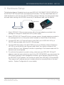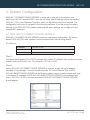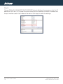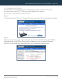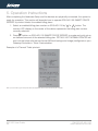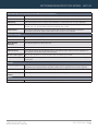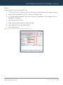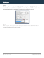
1
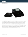
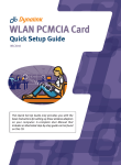
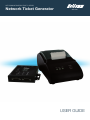
NETCOMM INFRASTRUCTURE™ SERIES
Network Ticket Generator
AG1100
USER GUIDE
Preface
This manual provides information related to the installation, operation, and application of this
device. The individual reading this manual is presumed to have a basic understanding of
telecommunications terminology and concepts.
If you find the product to be broken or malfunctioning, please contact technical support for
immediate service by email at [email protected]
For product update, new product release, manual revision, or software upgrades, please visit
our website at www.netcomm.com.au
Important Safety Instructions
With reference to unpacking, installation, use and maintenance of your electronic device, the
following basic guidelines are recommended:
Do not use or install this product near water, to avoid fire or shock hazard. For
example, near a bathtub, kitchen sink or laundry tub, or near a swimming pool. Also,
do not expose the equipment to rain or damp areas (e.g. a wet basement).
Do not connect the power supply cord on elevated surfaces. Allow it to lie freely. There
should be no obstructions in its path and no heavy items should be placed on the
cord. In addition, do not walk on, step on or mistreat the cord.
Use only the power cord and adapter that are shipped with this device.
To safeguard the equipment against overheating, make sure that all openings in the unit
that offer exposure to air are not blocked.
Avoid using a telephone (other than a cordless type) during an electrical storm. There
may be a remote risk of electric shock from lightening. Also, do not use the telephone
to report a gas leak in the vicinity of the leak.
Never install telephone wiring during stormy weather conditions.
WARNING
Disconnect the power line from the device before servicing.
AG1100 User Guide
2
YMLCR-UG-AG1100
www.netcomm.com.au
NETCOMM INFRASTRUCTURE SERIES - AG1100
Copyright
Copyright©2010 NetComm Limited. All rights reserved.
The information contained herein is proprietary to NetComm Limited. No part of this
document may be translated, transcribed, reproduced, in any form, or by any means without
prior written consent of NetComm Limited
NOTE: This document is subject to change without notice.
Save Our Environment
When this equipment has reached the end of its useful life, it must be taken to a recycling
centre and processed separate from domestic waste.
The cardboard box, the plastic contained in the packaging, and the parts that make up
this router can be recycled in accordance with regionally established regulations. Never
dispose of this electronic equipment along with your household waste. You may be subject
to penalties or sanctions under the law. Instead, ask for disposal instructions from your
municipal government.
Please be responsible and protect our environment.
YMLCR-UG-AG1100
www.netcomm.com.au
AG1100 User Guide
3
Table of Contents
Introduction�������������������������������������������������������������������������������������������������������������������������� 6
1.1 Overview of Network Ticket Generator����������������������������������������������������������������������������������������� 6
2. Device Overview������������������������������������������������������������������������������������������������������������� 10
2.1 Panel Overview�������������������������������������������������������������������������������������������������������������������������� 10
3. Hardware Setup�������������������������������������������������������������������������������������������������������������� 13
4. System Configuration����������������������������������������������������������������������������������������������������� 15
4.1 SDS-AG1100 SMART DEVICE SERVER������������������������������������������������������������������������������������ 15
4.2 Gateway/Controller�������������������������������������������������������������������������������������������������������������������� 17
5. Appendix A. SDS-AG1100 SMART DEVICE SERVER Web Interface Summary���������� 22
6. Appendix B. Firmware Upgrade������������������������������������������������������������������������������������ 24
Federal communication commission interference statement������������������������������������������������������������� 27
Product warranty������������������������������������������������������������������������������������������������������������������������������ 29
AG1100 User Guide
4
YMLCR-UG-AG1100
www.netcomm.com.au
Introduction
Introduction
1.1
Overview of Network Ticket Generator
Whether you are operating a wireless hotspot service for generating revenue or providing free
but controlled wireless internet access to guests, it would be handy to both the operators and
the wireless users if the account information (such as username, password, SSID and etc.)
can be readily output to PRT-AG1100 Thermal Printers and printed out as account tickets.
SDS-AG1100 SMART DEVICE SERVER is designed specifically to operate in conjunction
with specific NetComm Internet Access Controllers (IAC) and Wireless Hotspots. Typical serial
Thermal Printers on the market today may or may not be IP network ready, the SDS-AG1100
SMART DEVICE SERVER is designed to make the serial IP converter networkable to work
with the IAC and Wireless Hotspot such as the IAC3000 and HS1100
AG1100 User Guide
6
YMLCR-UG-AG1100
www.netcomm.com.au
NETCOMM INFRASTRUCTURE SERIES - AG1100
The SDS-AG1100 SMART DEVICE SERVER and the PRT-AG1100 Thermal Printer combo set
are called Network Ticket Generator.
The followings are typical application scenarios:
A small business who wishes to quickly set up a wireless service hotspot for charged
internet service may purchase a Gateway, and a Network Ticket Generators set. The
Gateway alone serves as an AP and a gateway, Network Ticket Generator enables the
registration operator to generate and issue acounts via push buttons on the SDSAG1100 and hand out the account ticket printed out by PRT-AG1100 Thermal Printer.
A corporate has several sites. Deployed at the reception area of each site are with
a SDS-AG1100 and a PRT-AG1100. Guests who need wireless connection to
the internet simply need to request the receptionist and obtain a slip with account
information. The guest account will automatically expire after the pre-configured time.
A hotel has a Controller/Gateway and multiple APs within it’s hospitality areas. Multiple
sets of Network Ticket Generator are distributed at the service desks and lounge
counters. The service clerks are able to create accounts for their guests with charged
or free internet service depending on the hotel’s service model.
YMLCR-UG-AG1100
www.netcomm.com.au
AG1100 User Guide
7
Below are two network diagrams examples using the Network Ticket Generator set.
1) One Gateway with one Network Ticket Generator set
SDS-AG1100
PRT-AG1100
Controller / Gateway
2) One Gateway with multiple Network Ticket-Generator sets
Controller / Gateway
SDS-AG1100
PRT-AG1100
SDS-AG1100
PRT-AG1100
Note:Though SDS-AG1100 SMART DEVICE SERVER is specifically designed to for NetComm IAC3000 and HS1100 on-demand account generation and
operates with the PRT-AG1100 Thermal Printer, it can also be deployed independently to connect other RS232 devices to an Ethernet network for
remote operation. If you will be deploying SDS-AG1100 independently to manage other serial devices, please carefully set the Serial Settings in SDSAG1100 SMART DEVICE SERVER to match the operating needs of your serial device.
Note:
If you connect other serial device to SDS-AG1100 SMART DEVICE SERVER and are unable to remotely operate your connected serial device, please check that:
The settings under Serial Settings of SDS-AG1100 are configured to match your serial device operating requirements.
If your serial device application operates on pure serial communication then you need to setup a COM port redirector.
AG1100 User Guide
8
YMLCR-UG-AG1100
www.netcomm.com.au
Device Overview
2. Device Overview
2.1 Panel Overview
Top panel
Main panel
Bottom panel
AG1100 User Guide
10
YMLCR-UG-AG1100
www.netcomm.com.au
NETCOMM INFRASTRUCTURE SERIES - AG1100
Top Panel
Function
Description
Adapter Socket
(12V/1A)
The power socket for connecting to an external power source through the power adapter
provided in the package.
DC Socket (DC12V)
The power socket for connecting to an external power source through a DC power supply.
Restart Button
Press to restart SDS-AG1100 SMART DEVICE SERVER.
Ethernet Port
Ethernet port for connecting to a Controller/Gateway.
Main Panel
LED indicators
Power
Turned on when properly connect to power supply.
COM 1
Turned on when output is switched to COM1.
COM 2
Turned on when output is switched to COM2.
Note: W
hen COM 1 and COM 2 are blinking simultaneously, this means that Terminal Server configuration is not set correctly. Please check the settings in Terminal Server
of your Gateway/Controller. When COM 1 and COM 2 are turned on simultaneously, this means that the system is in safe mode.
Link / Act
Turned on when LAN port is connected to an upstream networking device such as a switch or
Gateway/Controller.
100 Mbps
Turned on when LAN port is connected.
7 Segment
Displays an integer between 0 ~ 9 which indicates the billing plan number selected.
Buttons
Function
For future use — no function with current firmware.
Increase the numeric display for selecting a billing plan number.
For switching the output to COM1 or COM2.
Press this button followed by selecting a number and press Enter will perform a specific action.
The available combinations are as follows:
FUNTION + 1 + ENTER: Print out the IP address of SDS-AG1100 SMART DEVICE SERVER.
FUNTION + 8 + ENTER: Enter panel test mode.
FUNTION + 9 + ENTER: Reset SDS-AG1100 SMART DEVICE SERVER to factory default.
FUNTION + 0 + ENTER: Lock the panel of SDS-AG1100 SMART DEVICE SERVER. To Unlock
select your lock number and press ENTER
Decrease the numeric display for selecting a billing plan number.
Create and print out an account for the chosen billing plan.
Bottom Panel
Function
Description
COM 1
Serial Port for connection with a PRT-AG1100 Thermal Printer.
COM 2
Serial Port for connection with a PRT-AG1100 Thermal Printer. Used for back up when COM 1
malfunctions.
YMLCR-UG-AG1100
www.netcomm.com.au
AG1100 User Guide
11
Hardware Setup
NETCOMM INFRASTRUCTURE SERIES - AG1100
3. Hardware Setup
The following diagram illustrates how to connect SDS-AG1100 SMART DEVICE SERVER to
the PRT-AG1100 Thermal Printer and Gateways/Controllers. The steps described below to
install hardware to work with the HS1100 Wireless Hotspot Gateway; the same logical steps
are used when working with IAC3000 where only IP addresses used may be different.
SDS-AG1100
Controller / Gateway
PRT-AG1100
1. Attach SDS-AG1100 to a power source, either through adaptors provided in the
package or through DC socket with a DC power supply.
2. Attach PRT-AG1100 Thermal Printer to a power source, through adaptors provided in
the package and turn on the power switch situated on the left side of the device.
3. Connect PRT-AG1100 Thermal Printer to the COM1 port of SDS-AG1100 by a
RS-232 cable provided within the AG1100 package.
4. Connect SDS-AG1100 to the LAN1/LAN2 port of your Wireless Hotspot Gateways
HS1100 or the IAC3000 by an Ethernet cable. Note: You need to connect to the
correct LAN port if your Gateway/Controller is operating in Port-based mode with Ondemand user server applied.
5. To verify that the system is up and running, make sure your SDS-AG1100 has IP
address under the same subnet as used in the HS1100/IAC3000, you may access the
IAC/hotspot gateway’s web management interface, go to Network Utilities and ping
the SDS-AG1100 IP address. You should see replies from SDS-AG1100 successfully.
That means the IP address and port numbers are set up correctly.(Refer to the next
section – System Configuration for more details)
YMLCR-UG-AG1100
www.netcomm.com.au
AG1100 User Guide
13
System Configuration
NETCOMM INFRASTRUCTURE SERIES - AG1100
4. System Configuration
SDS-AG1100 SMART DEVICE SERVER is designed to operate in conjunction with
NetComm HS1100 and IAC3000. If you are not using default settings, before connecting
SDS-AG1100 to your Gateway/Controller, some configurations steps are required. The
configuration instruction is covered in the following sections. If you are using the default
settings in the SDS-AG1100, please make sure the same settings are configured in the
hotspot/IAC gateways.
4.1 SDS-AG1100 SMART DEVICE SERVER
SDS-AG1100 SMART DEVICE SERVER supports web based configuration. By factory
default, SDS-AG1100 web interface can be accessed with the following default
IP address
IP address:
192.168.110.250
Subnet Mask:
255.255.255.0
Default Gateway:
192.168.110.1
Step1:
Configure administrator PC’s TCP/IP settings with a static IP address that is under the same
subnet mask as SDS-AG1100. For example: 192.168.110.20
Step2:
Attach SDS-AG1100 SMART DEVICE SERVER to a power supply using the adapter
provided in the package. Connect the administrator PC to the Ethernet Port of SDSAG1100 SMART DEVICE SERVER via an Ethernet cable. Launch a web browser and type
in the default IP address of SDS-AG1100 SMART DEVICE SERVER in the address field
(http://192.168.110.250), the web interface of SDS-AG1100 SMART DEVICE SERVER
should appear.
YMLCR-UG-AG1100
www.netcomm.com.au
AG1100 User Guide
15
Step3:
Change SDS-AG1100 SMART DEVICE SERVER Network Settings if necessary so that the IP
address of SDS-AG1100 is under the same subnet as the Gateway/Controller’s interface and
the port number used in both side are the same. Click Apply to save the settings.
AG1100 User Guide
16
YMLCR-UG-AG1100
www.netcomm.com.au
NETCOMM INFRASTRUCTURE SERIES - AG1100
4.2 Gateway/Controller
Configuration procedures are similar on all Gateway/Controller models, the following
instruction steps uses HS1100 Wireless hotspot gateway as illustration.
Note: The screenshots may be slightly different for your Gateway/Controller model.
Step1:
Connect administrator PC to your Gateway/Controller and access the web management interface.
Step2:
Enter the configuration page of the wireless hotspot’s LAN 1 & LAN2 settings (in IAC3000,
LAN settings are under Service Zone), check to make sure that the network settings of
SDS-AG1100 are under the same subnet as in the LAN settings (Service Zone).
YMLCR-UG-AG1100
www.netcomm.com.au
AG1100 User Guide
17
Step3:
Go to the configuration page for On-demand authentication; click Configure to edit Terminal
Server settings.
In HS1100, navigate to User Authentication> Authentication Configuration > On-Demand User
Server> Terminal Configuration > Enter the IP address (192.168.110.100) and Port (5000) of
SDS-AG1100 SMART DEVICE SERVER.
(In IAC3000, navigate to User Authentication> Authentication Configuration > General Settings
> Terminal Configuration > Enter the IP address and Port number of SDS-AG1100.)
Step4:
Edit and enable desired billing plans.
AG1100 User Guide
18
YMLCR-UG-AG1100
www.netcomm.com.au
Operation Instructions
5. Operation Instructions
After completing the Hardware Setup and the devices are physically connected, the system is
ready for operation. This section will describe how to operate SDS-AG1100 SMART DEVICE
SERVER to printout tickets for enabled billing plans.
1. Select an enabled billing plan number on SDS-AG1100 by
or
button. The
numeric LED display on the center of the device represents the billing plan number
currently selected.
2. Press
button on SDS-AG1100 SMART DEVICE SERVER to create and print out an
on-demand account of the selected billing plan. PRT-AG1100 THERMAL PRINTER will
print out the ticket with the text format (Without background image) configured on your
Gateway/Controller in Ticket Customization.
Example of a Thermal Ticket printout:
Note: If you are unable to get a ticket printout after pressing ENTER, please check if the selected plan is enabled.
AG1100 User Guide
20
YMLCR-UG-AG1100
www.netcomm.com.au
Appendix
5. Appendix A. SDS-AG1100 SMART DEVICE
SERVER Web Interface Summary
The attribute setting in this web interface is for COM 1 only. COM 2 uses default settings that
are unchangeable.
AG1100 User Guide
22
YMLCR-UG-AG1100
www.netcomm.com.au
NETCOMM INFRASTRUCTURE SERIES - AG1100
Serial Settings (corresponding to PRT-AG1100 Thermal Printer)
Data Baud Rate
Select the desired baud rate. (The number of characters per second transferred)
Data Bits
Select the number of bits in each character.
Data Parity
Choose between Even or Odd for error detection, or select None for no error detection.
Stop Bits
Choose the number of stop bits to be sent at the end of every character. Electronic devices
usually use 1 bit, slower electromechanical devices use 1.5 bit.
Flow Control
Choose the method of flow control to pause and resume the transmission of data to
coordinate with printer speed. Select None if flow control is not required.
Network Settings
Static IP Address
The static IP address assigned to SDS-AG1100.
Static Subnet Mask
The subnet mask of SDS-AG1100.
Static Default
Gateway
The default gateway of SDS-AG1100.
Static DNS Server
Set the DNS server used by SDS-AG1100.
Transmit Timer
TCP transmit timer, set the desired value or use default value. When the timer expires for a
sent packet, sender will retransmit the packet.
Server Listening Port
Set the port number for communication with the Gateway/Controller.
Lock Password
This attribute is the integer between 0 ~ 9 that will be set as the password for unlocking the
main panel.
Utilities
Firmware Upgrade
Firmware of SDS-AG1100 can be upgraded by clicking the Apply button. Note: Upgrade
preparations are required before upgrade, please refer to Appendix B. Firmware Upgrade
Restart
Click Apply to restart SDS-AG1100 device.
Reset to Factory
Default
Click Apply to reset SDS-AG1100 to factory default settings.
Status
Software Version
The current software version running on SDS-AG1100.
YMLCR-UG-AG1100
www.netcomm.com.au
AG1100 User Guide
23
6. Appendix B. Firmware Upgrade
Software tools tftpd32 is required in the upgrade procedure, please download and install
tftpd32 before you proceed further.
Note: Tftpd32 can be downloaded from the following link: http://tftpd32.jounin.net/tftpd32.html
Step1:
Place the new firmware of SDS-AG1100 SMART DEVICE SERVER on a local location
(for example desktop) in the PC that is accessing SDS-AG1100’s web interface and
performing the upgrade.
Step2:
Configure the TCP/IP settings of your PC with an IP address under the same subnet mask as
SDS-AG1100. For example 192.168.110.20
AG1100 User Guide
24
YMLCR-UG-AG1100
www.netcomm.com.au
NETCOMM INFRASTRUCTURE SERIES - AG1100
Step3:
Launch tftpd32 and click the DHCP tab.
1. In “Current Directory” field, browse for the location path where the firmware is stored.
2. Enter the IP address of your PC in “Server interfaces” field.
3. In “IP pool starting address” field, enter the start IP address of an IP segment that is
available for allocation.
4. Set the size of the IP pool.
5. Enter the firmware filename in “Boot file field”.
6. Enter 255.255.0.0 in the “Mask” field.
7. Click Save button.
Note: Please make sure that the location path and the firmware for upgrade is correct.
YMLCR-UG-AG1100
www.netcomm.com.au
AG1100 User Guide
25
Step4:
Click Apply of Firmware Upgrade in SDS-AG1100’s web interface. SDS-AG1100 will
automatically restart and connect to tftpd32 server set in Step3 as a DHCP client, download
the firmware and perform the upgrade. Progress can be observed on tftpd32.
Step5:
When complete, check the information displayed at Software Version, SDS-AG1100 have
successfully upgraded to the new firmware.
AG1100 User Guide
26
YMLCR-UG-AG1100
www.netcomm.com.au
NETCOMM INFRASTRUCTURE SERIES - AG1100
Federal Communication Commission interference statement
This equipment has been tested and found to comply with the limits for a Class B digital
device, pursuant to Part 15 of the FCC Rules. These limits are designed to provide
reasonable protection against harmful interference in a residential installation. This equipment
generates, uses and can radiate radio frequency energy and, if not installed and used in
accordance with the instructions, may cause harmful interference to radio communications.
However, there is no guarantee that interference will not occur in a particular installation. If
this equipment does cause harmful interference to radio or television reception, which can be
determined by turning the equipment off and on, the user is encouraged to try to correct the
interference by one of the following measures:
Reorient or relocate the receiving antenna.
Increase the separation between the equipment and receiver.
Connect the equipment into an outlet on a circuit different from that to which the
receiver is connected.
Consult the dealer or an experienced radio/TV technician
for help.
YMLCR-UG-AG1100
www.netcomm.com.au
AG1100 User Guide
27
FCC Caution:
Any changes or modifications not expressly approved by the party responsible for compliance
could void the user’s authority to operate this equipment.
This device complies with Part 15 of the FCC Rules. Operation is subject to the following
two conditions:
(1) This device may not cause harmful interference, and (2) this device must accept any
interference received, including interference that may cause undesired operation.
IMPORTANT NOTE:
FCC Radiation Exposure Statement:
This equipment complies with FCC radiation exposure limits set forth for an uncontrolled
environment. This equipment should be installed and operated with minimum distance 20cm
between the radiator & your body.
This transmitter must not be co-located or operating in conjunction with any other antenna
or transmitter.
AG1100 User Guide
28
YMLCR-UG-AG1100
www.netcomm.com.au
NETCOMM INFRASTRUCTURE SERIES - AG1100
Product warranty
The warranty is granted on the following conditions:
1. This warranty extends to the original purchaser (you) and is not transferable;
2. This warranty shall not apply to software programs, batteries, power supplies, cables
or other accessories supplied in or with the product;
3. The customer complies with all of the terms of any relevant agreement with NetComm
and any other reasonable requirements of NetComm including producing such
evidence of purchase as NetComm may require;
4. The cost of transporting product to and from NetComm’s nominated premises is your
responsibility; and,
5. NetComm does not have any liability or responsibility under this warranty where
any cost, loss, injury or damage of any kind, whether direct, indirect, consequential,
incidental or otherwise arises out of events beyond NetComm’s reasonable control.
This includes but is not limited to: acts of God, war, riot, embargoes, acts of civil
or military authorities, fire, floods, electricity outages, lightning, power surges, or
shortages of materials or labour.
6. The customer is responsible for the security of their computer and network at all
times. Security features may be disabled within the factory default settings. NetComm
recommends that you enable these features to enhance your security.
YMLCR-UG-AG1100
www.netcomm.com.au
AG1100 User Guide
29
GNU General Public License
This product includes software code that is subject to the GNU General Public License (“GPL”)
or GNU Lesser General Public License (“LGPL”). This code is subject to the copyrights of one or
more authors and is distributed without any warranty. A copy of this software can be obtained by
contacting NetComm Limited on +61 2 9424 2059.
The warranty is automatically voided if:
1. You, or someone else, use the product, or attempts to use it, other than as specified
by NetComm;
2. The fault or defect in your product is the result of a voltage surge subjected to the
product either by the way of power supply or communication line, whether caused by
thunderstorm activity or any other cause(s);
3. The fault is the result of accidental damage or damage in transit, including but not
limited to liquid spillage;
4. Your product has been used for any purposes other than that for which it is sold, or in
any way other than in strict accordance with the user manual supplied;
5. Your product has been repaired or modified or attempted to be repaired or modified,
other than by a qualified person at a service centre authorised by NetComm; and,
6. The serial number has been defaced or altered in any way or if the serial number plate
has been removed.
AG1100 User Guide
30
YMLCR-UG-AG1100
www.netcomm.com.au
NETCOMM INFRASTRUCTURE SERIES - AG1100
Limitations of warranty
The Trade Practices Act 1974 and corresponding State and Territory Fair Trading Acts
or legalisation of another Government (“the relevant acts”) in certain circumstances imply
mandatory conditions and warranties which cannot be excluded. This warranty is in addition
to and not in replacement for such conditions and warranties.
To the extent permitted by the Relevant Acts, in relation to your product and any other
materials provided with the product (“the Goods”) the liability of NetComm under the Relevant
Acts is limited at the option of NetComm to:
Replacement of the Goods; or
Repair of the Goods; or
Payment of the cost of replacing the Goods; or
Payment of the cost of having the Goods repaired.
All NetComm ACN 002 490 486 products have a standard 12 months warranty from date of
purchase. However some products have an extended warranty option (refer to packaging). To
be eligible for the extended warranty you must supply the requested warranty information to
NetComm within 30 days of the original purchase by registering on-line via the NetComm web
site at www.netcomm.com.au
YMLCR-UG-AG1100
www.netcomm.com.au
AG1100 User Guide
31
NETCOMM LIMITED Head Office
PO Box 1200, Lane Cove NSW 2066 Australia
P: 02 9424 2070
F: 02 9424 2010
E: [email protected]
W: www.netcomm.com.au
DYNALINK NZ 12c Tea Kea Place, Albany, Auckland,
New Zealand P: 09 448 5548
F: 09 448 5549
E: [email protected]
W: www.dynalink.co.nz
Product Warranty
NetComm products have a standard 12 months warranty from date of purchase. However some
products have an extended warranty option, via registering your product online at the NetComm website
www.netcomm.com.au
Technical Support
If you have any technical difficulties with your product, please refer to the support section of our website.
www.netcomm.com.au/support
Note:NetComm Technical Support for this product only covers the basic installation and features outlined in the Quick Start Guide. For further
information regarding the advanced features of this product, please refer to the configuring sections in the User Guide or contact a
Network Specialist.
Trademarks and registered trademarks are the property of NetComm Limited or their respective owners. Specifications are subject to change without notice. Images
shown may vary slightly from the actual product.