1
Section 2 (28)
Ignition systems
700
1982TP 31397/1
July 1989
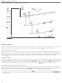
This manual deals with the following engine variants :
Engine
Model year(s)
Engine
Model year(s)
819 E
B 23 E
B 23 FT
B 28 A
B 28 ElF
B 230 A
8230E
B 230 F
1984
1984
1984-88
1982-85
1982-86
1985-86
19851985-
B 230 FT
B 230 K
B 200 E
B 200 K
B 280 ElF
B 204 E
8234F
1985198519851985198619891988-
Volvos are sold in versions adapted for different markets.
These adaptations depend on many factors including legal, taxation and market requirements.
This manual may therefore show illust rations and text
wh ich do not apply to ca rs in you r count ry.
Volvo owners planning to export their carls) to another
country should investigate the applicable safety and exhaust emission requirements. In some cases it may be impossible to comply with these requirements.
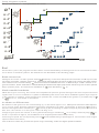
Group 28 Ignition systems
Contents
Group 28 Ignition systems
Contents
Pag e
Introduction
Design and function:
Overview
.
Review of electronic ignition systems - I .............................•...........
Review of electronic ignition systems - II (type EZ-K and Rex-J) . . . . . . . .•. . . . • . . . . . .
3
4
6
General
Function of ignition system ; combustion theory in brief ....... . ..... ... . .. ........ 9
Ignition systems - basic parameters. . .. . . . . . . . . . . . . . . . . . . . . . . . . . . . •. . . . •. . . . . . . .. 11
Contact-breaker versus electronic systems ...................... . .. •....•. ........ 13
Components
Control unit..................................................... ..... ....
Control unit, power stage and ignition coil configurations..................
Power stage and ignition coil.. . . .. . . .. . . . .. . . . . . . .. .. .. . . . . . . .•. . . •• . .•. . . .. . ...
Distributor ............... . ..............................................•.......
14
16
17
19
Speed and crankshaft position information
Hall generator . . . . . . . . . . . . . . . . . . . . . . . . . . . . . . . . . . . . . . . . . . . . . . . . . . . . . • . . . . • . . . . . .. 20
22
Speed/position pick-up and flywheel configuration
Load information
Induction manifold vacuum .. . . .. . . .. . . .. . . . . . . . . . . . . . . . . . . . . . . . . . . . . . • .. . . . . . . .. 25
Fuel injection system control unit.. . . . . . . . . . . . . . . . . . . . . . .•.. . . . . . . . . . .•. . . . . . . . .. 26
Compensation functions
Theory of knock. . . . . . . . . .
... .. .. .. .. .•.. .. .. .. .. .. .. .. .. .. .. .
Knock sensor ...... . . . . ...................... . ....... . ..•.... . ....... . ..........
Knock co ntrol ................................•.......•...... . •.......•..........
. .... . ... .. ... • .... • .....
Knock-controlled fuel enrichment . . . . . . . . . . . . . . . . . . •.
Throttle switchlidling switch ............... . ....... . ....... . .. • .......•....•.....
Temperature sensor .............................. . • ..•... . •..•.......•... • • .....
28
30
32
39
40
41
System descriptions
TSZ .. .. . . . .. . . . . . .. . . .. . . . .
. ... . ...•.
.
TZ-28H .............................•...
Renix·F. . .. .. . . . . . .. •. . . . .. .•. . .. .. . •. . . .. . •.......................•...........
EZ·l02K .. . ....•.... • ....... • .... . ..•.... . ..•....... . ..•... .. ..•.... . ....•......
EZ-1 17K .......•....•.... . .. . .... . .. .. ... . .. • .......•..•.... . ..•.... . .... . ......
EZ-118K .........................•....... . ....... . ....... . ....... . .......•......
EZ-115K ............ . ......... ..
..•. . . .... . .. • ... ...
. .....•....•......
EZ-116K. ...................... . . . . .....
. .. • . ..•... • .
. .....•....•..
Rex·1 . . . . . . . . . . . . . . . . . . . . . . . . . . . . . . . . . . .
. .. . . ....... •. ... ..
Diagnost ic system, EZ-116K and Rex-I
.
43
44
45
47
4"
51
55
58
60
63
Group 28 Ignition systems
Contents
Test equ ipment ...... • ....•.... • ..•...••..•...... . •..•......••..•....•.......... 68
Instructions . . . . . . . . . . . . . . . . . . . . . . . . . . . . • . . . . . . . • . . • . . • . . . . . . . • . . . . • . . • . . . . . . . . .. 69
Specifications ......................•....•.. , ...• • ..•..•....... • ... • •........ 71 - 78
Bre. kerless ignit ion system s ........... • ..•.... • .. • ..•.......•....... • .......... 79
Fault tracing ...... . . . ........ ... .. • .. • . . . . , .. • .. • . . .. , .. •. .•. . ..•.. • . ...... . .... 105
TSZ-4 . . . . .... . .... . ... . ... ...... . • . .. .. .. • . . • . . .. . . , • . . •. . . . .. .• . . . • •. . ..... . ,. 106
Aenix·F .. . . . .... . . . . .• .... • .......•...... . •..•....... • .. • ..... . .•.......•.. . .... 115
TZ·28H .. . ........ • ..•.•..•.......•.......•..........•.. • ....... • ....•... . ...... 125
EZ-l02K .............•... • • .. • ....•... • •.. • ..•. _. • • • • • ..•..•.... • ..• • •... • ...... 135
EZ-115K ..........•.. • ....•... . •.. • ....•.. • .......•.. • ..•....• . . • ....•.......... 151
EZ· 117/ 118K
_• ....•....... • ....... • .......... • ..•.... .. • • .......•.......... 169
EZ·116K
187
Aex-I ............. . . . ........ ... . . . . . . . .... . . ....... .. . . ..••. . . . . . ...... . .. . .... 21 5
See Service Manual. Fault tracing, repair and maintenance, Section 2 (23), B 23, B 200,
B 230 ET Engines. 740, 760 Turbo, for details of Motronic systems. (Order No. TP 30949/1)
Index, page 227
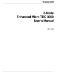
Order No.: TP 31397/ 1
Supersedes TPI31059/ 1 USA
We reserve the right to make changes
w ithout prior notification
2
e VOlVO NORTH AMERICA CORPORATION
Group 28 Ignition systems
Introduction
Introduction
Comprehensive development work by Volvo has resulted in the design of engines boast ing high performance, low
fuel consumption, cleaner exhaust gases, a high standard of reliability and simplified service procedures. The everincreasing use of microelectronics for the control and regulation of ignition and fuel systems has been one of the
most significant factors in this development.
Compared with their mechanical counterpart s, elect ronic (or microprocessor-controlled) ignition systems offer advantages such as greater reliability, optimum timing under all driving co nditions and few moving parts, reducing
service requirements t o a minimum . A s a result, Volvo has, in recent years, co mplet ely replaced it s relatively simple,
mechanically-controlled, contact-breaker systems with sophisticated systems controlled by microprocessors and
electronics.
Equipping system control units with various additional program functions, and integrating them with other control
systems and componen ts, has enabled traditional ignition systems 10 be augmented by features such as temperature-eompensated timing for faster engine warm-up, improved exhaust gas composition and lower working temperature. Other functions which may be con trolled by an electronic ignition system control unit include fuel cut-off
under engine braking (deceleration) conditions and ignition retardation in individual cylinders to eliminate knock.
Volvo markets a wide range of models with a series of engine options. This, combined with rapid developments in
the field of electronics, means that a wide variety of electronic ignition systems of different types and degrees of refinement now exist.
Systems of this type impose completely new demands on fault-tracing procedures. A certain basic understanding of
the input and output signals, the manner in which the componen t s are connected and the function/purpose of each
is essential to an understanding of the types of fault which may arise, and to ensuring that the correct diagnosis is
made in each case.
Sensors and pick-ups providing fa st and precise information on the prevailing running conditions are vital to ensure
that the electronics con trol the working componen ts of the system rel iably and accurately.
This manual deals with the electronic ignition systems used by Volvo on it s 700 series models, in terms of design
and function , as well as fault tracing, repai r and maintenance. The first part of the manual consists of a description of
the features, components and compensation functions common to the various systems, followed by a description of
each individual system and some of the special functions peculiar to each. The appropriate wi ri ng diagrams are i ncluded.
3
Group 28 Ignit;on systems
Design and function - Overview
Review of electronic ignition systems - I
A
TZ28"
IlENIX
F
~
~ ··oc
a
B
;;l
D
C
J
~
E
F
G
H
trn ~ ~
';"
~'
~~~
147 077
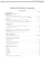
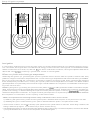
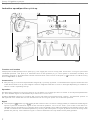
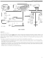
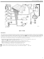
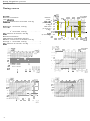
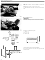
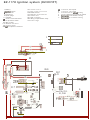
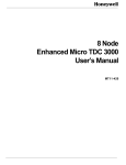
The above figure shows the major componen ts of each of the systems described below.
Summary
Control system
The control unit (A ) houses the electronic circuits and the various program functions needed to compute the timing.
The power stage (Bl controls the pri mary current in the ignition coil in response to con trol signals from the con trol
unit. The power stage may either be an integral part of the control unit or a separate unit assembled with it. The function of the distributor (e) is to deliver the high-tension pulse i nduced in the secondary winding of the ignition coil to
the correct spark plug. The distributor may be driven either by bevel gearing (i n which case it is installed vertically) or
directly from the camshaft (horizontally i nstalled units). In systems in which the rotor arm is the only moving part
(such as types which employ inductive speed p ick-ups) the limi ng cannot be varied by alteri ng the position of the
distributor.
Sensors
The rema ining components in the table (D-E) comprise part of the sensor system. Together with the con trol unit,
these supply informat ion on prevailing engine running conditions.
Basi c parameters
The control unit is supplied with information on eng ine speed and c rankshaft position (D) either by a Hall generator
activated by a trigger rotor (with four vanes) mounted on the rotor shaft or by an inductive pick-up mounted close to
the flywheel (on manuals) or ca rrier pIa Ie (automatics). In th is case, the periphery of the flywheel/carrier plate is provided with a ser ies of holes whose passage is detected by the p ick-up and indicated in the form of electrical signals.
The eng ine load (E) is measured either by means of a vacuum l ine anached t o the intake manifold or, if the eng ine is
equipped w ith an LH-Jetron ic fuel injection system (i.e. most engines equ ipped with EZ-K ignition systems). by an
ai r mass meter (see next ill ustration ). The various signals - engine speed, crankshaft position and enQine load com prise information which is used by ignition systems o f all types to compu te the timi ng .
4
Group 28 Ignition systems
Design and function - Overview
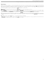
Review of electronic ignition systems - I
TSZ: An electronic ignition system in which the function performed by contact breaker points in conventional systems is carried out by an inductive pulse generator. (Roughly translated, the abbreviation TSZ - which stands for
Transistor Spolen lundung - means 'Transisto rized coil ignition'.) The pulse generator signals are transmitted to a
'control unit' which regulates the coil charging period. Th e system also inco rporate s a cen t rifugal generator and a
baltast resistor. Designated TSl-4, the variant for 6-cylinder engines (B28A1EiF) was used on 700 series cars from
1982 to 1986.
TZ·28H: As the designation indicates, this is a transistorized system employing a Hall generator to supply the signals
used by the 'control unit' to control the pri mary current i n the ignition coil. A vacuum advance un it on the distributor
varies the timing with engine load . Although the system was used on some 700 series models produced in 1984, it
was almost completely superseded by other systems in 1985 as the new family of engines entered production. (Unlike other systems discussed in this con text, TZ-28H is not fully electronic; indeed. it is usually regarded as one of the
group of transistorized systems.)
RfNIX-F: The name is a trademark of the Bendix company. In this system , the control unit. power stage and ignition
coil comprise a single unit. Since '985, Renix-F has been used on 7405 equi pped with the B 200 K engine and Salex
c.rburettor.
• The letters used in the deSignations 01 the var ious sy stems are usually derived fro m the maker's native language. wh ile the fig ures usually denote the verSion and/or variant desig nation .
5
Group 28 Ignition systems
Design and function - Overview
Review of electronic ignition systems - II
(Type EZ-K and Rex-I)
A
B
~
I'u\..~
['\l.
I/'~
~ l ...
~
C
0
Ud'"
--
E
F
G
H
tJJ
~ '"
EZ1m ~ r.v\'\~. ~ ~ 0 (jf
EZ($ ~ ~)~ ~ 0 ~ q
n,
EZ]I ~ b ~ &, a q
EZ[ij 0 ~ b ~ CJ a d
REX- ('
\J -$ ~ b iii QJ q
EZ-
102K
117K
118K
,
U-"
~~
~
(3P G
"
~
/'
115K
~
u:.-'
116K
I
I~ ,')
141071
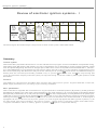
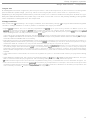
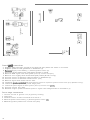
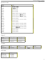
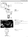
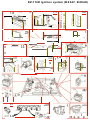
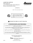
The illustration shows the main components of type EZ-K and Aex-I ignition systems.
Common features :
An abbreviation of the German term Elektronischer Zundung m it Klopfregulung (roughly, 'Electronic ignition with
knock sensor') the designation EZ-K describes a group of systems manufactured by the Bosch company. The various
systems i n the EZ-K group are relatively similar in terms of functions and components. All feature microprocessor
control and incorporate a memory which is programmed with a family of ideal timing curves for the particular engine. Each system also includes a sensor which detect s engine knock and retards the ignition in respon se to a memory program which is individu al to each cylinder. This means that the timing in each cylinder may vary at any given
instant.
As column E indicates, systems in this group are normally supplied w ith engine load information by an air mass
meter located in the intake system. A measure of the quantity of air supplied to the engine, the ai r mass meter signal
is transmitted to the LH-Jetronic control un it (in which it is converted and used to determine the quantity of fuel to be
injected) and then to the ignition system control unit.
Differences
Within the EZ-K group, the individual systems are distinguished by the timing curves used for different engine variants, by whether a Hall generator or inductive speed/position pick-up is used, and by when the ignition compensation functions are activated.
6
Group 28 Ignition systems
Design and function - Overview
Review of electronic ignition systems - II
EZ-l02K was i ntroduced in 1984 in conjunction with the launch of the 760 Turbo with the 823 FT engine and lH 2.1
fuel injection system on the American market. EZ-102K is equipped with a thermostat which transmits a signal to
one of the control unit terminals when the engine temperature becomes excessive. commanding it to advance the
timing if the throWe is closed. The fi rst EZ-K system to be used by Volvo, EZ-102K remained in production only for a
year before being superseded by more up-to-date variants according as the new family of engines was introduced.
EZ-117K is very similar to EZ-102K in configuration, although designed for the 8230 F and 8230 FT engines with the
lH..Jetronic 2.2 fuel injection system. The system was introduced with the new family of engines in 1985. The
8230 FT variant features a knock-controlled fuel enrichment function. like its predecessor, EZ-102K, the turbo engine
variant is equipped w ith a thermostat which activates a timing advance function to protect the engine from overheating .
EZ-118K differs most from the other systems in the group. due to the fact that it depends on a vacuum connection between the intake manifold and control unit to supply engine load information, rather than on a load signal supplied
by an air mass meter via the fuel system control unit. The system also employs an idling switch mounted on the
throttle pulley rather than a switch mounted on the throttle housing. EZ-118K was introduced in 1985 on the B 200 E.
8230 E and B 230 K engines. Two idling compensa ti on functions may be used on all EZ-1 18K varian ts. The 8230 K
va riants are equipped with a temperature sensor, while the control unit operates a solenoid valve which inte rrupts
the fuel supply under engine braking conditions. Most of the differences are attributable to the fact t hat the system is
used on carbura ted engines (now with Pierburg carburettors) and on E engines with the CI system (K-Jetronicl.
EZ-115K has been designed especially for the 8280 engine. Its features include two knock sensors (one for each bank
of cylinders), a position detector for No. 1 cylinder, a knock-controlled fuel enrichment function and an inductive
speedJposition pick-up mounted at the flywheel. Depending on the temperature sensor signal. the control unit can
apply tim ing compensation by retarding the ignition when the engine is cold to achieve faster heating of the coolant.
and by advancing it when the engine tends to run too hot. The system appeared in 1987 with the introduction of the
8280 engine to replace the B 28, and is, therefore, used only on the 760/780. EZ-1 15K is used in combination w ith LHJetronic 2.2 on both the E and F variants.
EZ-116K is a refinement of other EZ-K systems. However, it features advanced self-diagnostics which facilitate fault
tracing and monitoring . The control unit continuously mon itors the various sensors and functions, and any faults
present may be displayed w ith the aid of a d iagnostic un it mounted in the engine compartment. EZ-116K was introduced in 1988 on the 1&valve 8234F engine used in the 740 GlT. Unl ike other EZ-K systems used on 4-cyl inder
engines in the 700 series, EZ-116K is equipped with an inductive speedJposition pick-up mounted close to the flywheel instead of a Hall generator in the distributor. The system is used in combination with the very latest fuel injection system (LH·Jetronic 2.41.
Manufactured by 8endix, the Rex-I system is equi pped with the same type of diagnostic system as EZ-116K. Used in
conjunction with the Regina fuel injection system, Rex-I was introduced in 1989 on 8230 F engines sold in th e USA .
Compensation functions
However, most electronic ignition systems are equipped w ith additional sensors which enable the con trol unit to adjust the timing to compensate for unusual running conditions. Thus. sensors (F-H ) may be regarded as providing the
ignition system with compensa tion functions. In the event of engine knock (the phenomenon whereby th e fuel/air
mixture is ignited by a source other than the spark plug), the knock sensor (FI mounted on the engine wi ll transmit a
signal to the control unit commanding it to retard the ignition. Complete closure of the throttle is indicated by a throttle switchlidling switch (G). When the engine is idling. the control unit regulates the timing in accordance wi th an
'idling program ' to ensure optimum comfort, while the t iming under engine braking condi tions is controlled to minimize exhaust emissions. The signal supplied to the control unit by the temperature sensorhhermostat enables the
unit to apply the appropriate timing compensat ion when the engine temperature is unusually high or low.
7
Group 28 Ignition systems
Design and function
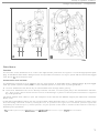
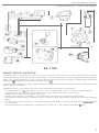
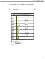
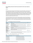
Overview
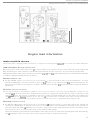
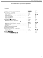
IGNITION SYSTEM
ENGINE
YEAR
TSZ-4
TSZ-4
TSZ-4
B 28 A
B 28 E
B 28 F
82-85
82-86
82-86
TZ-28H
TZ-28H
TZ-28H
B 19 E
B 23 E
B 230 A
84
B4
MOTRON'C
MOTRONIC
MOTRONIC
B 23 ET
8200 ET
B 230 ET
RENI X-F
REX-I
B 200 K
858585-
B 230 F
89-
EZ- l02K
EZ- l17K
EZ· l17K
EZ- 118K
EZ-118K
EZ-11 8K
EZ·'18K
EZ- 11 5K
EZ· 115K
EZ-1 16K
EZ-116K
EZ·116K
B 23 FT
8230 F
B 230 FT
84 (USA)
8!">-S8
B 200 E
B 230
B 230
B 230
B 280
E
K
K
E
B 280 F
B 234 F
B 230 F
B 204 E
8!">-S6
B4
85858585-86
878787888989-
N.B. Due to differences in model specifications from country to country. the number of control unit variants used for
the various ignition systems and eng ines may exceed that listed above.
8
Group 28 Ignition systems
Design and function - General
General
o
A
B
c
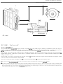
Function of ignition system; combustion theory in brief
Correct ignition tim ing
A. The function of the ignition system is to ignite the compressed fuel/air mixture in each cylinder at exactly t he correct instant. Ignition is followed by the propagation of a flame front through the combustion chamber until the complete charge has been burned. The combustion pressure. which is higher than that of the compressed mixture, generates a high force which drives the pist on downwards in the cylinder. (Although a proportion of the energy released
is converted into mechanical work by the crankshaft, most of the energy in the fuel (approx. 70%) is dissipated in the
form of cooting losses, exhaust gas losses and mechanical losses.)
To ensure that the ignition timing is as close as possible to the 'correct ' setting under all runn ing conditions, the timing must be adjusted continuously to take account of variations in the conditions. In other words, the optimum timing is not a fixed setting for each eng ine, but varies with factors such as engine speed, load, fuel /air ratio and temperature. Furthermore, the t im ing may be adjusted for optimum comfort, maximum torQue or maximum power as appropriate.
In the rest of this discussion, the term optimum tim ing shall be taken to mean a setting which takes account of all the
factors influenced by the ignition. In other words, it is a compromise between the demands of high power, low fuel
consumption and the cleanest possible exhaust emissions. The emergence of ever-stricter emission standards has
been the main factor in the development of ignition systems designed to optimize the combust ion process under all
running condit ions.
Earlv ignition
B. Early ignition prevents efficient expansion of the fuel/air mixture since the piston is sti ll travelling upwards tow ards TOC as the pressure rise occurs, generating an abnormally high pressure accompanied by an excessive temperature rise. As a consequence of early ignition, part of the unburnt fuel/air mixture may ignite spontaneously,
causing the engine to knock.
In general, early ignition also has an adverse effect on the exhaust emissions. The Quantity of unburnt hydrocarbons
(HC ) increases, while the pressure and temperature rises cause the nitrogen in the trapped air to react w ith the
oxygen to fOfm greater quantities of nitrogen monoxide (NO) and nitrogen dioxide (NO) Of NO.. oxides of nitrogen).
9
Group 28 Ignition systems
Design and function
A
General
B
c
late ignition
C. Late ign ition reduces engine power since the pist on is t ravelling downwards from ToC when the pressure r ise occurs. As a result, the engine does not ut ilize t he full energy content of the fuel . Although the concentrations of undesira ble constituents such as HC, CO, NO and N0 2 are lower under these conditions, the engin e require s more fuel t o
deliver the same output, producing a greater total volume of exhaust gases.
Effects on cylinder and exhaust gas temperatures
Advancing the ignition (i.e. generating the spark to ign ite the fuel /air mixture when the piston is further from ToC )
produces a h igher combustion temperature and a lower exhaust gas temperature than when the tim ing is ret ard ed.
Thi s is due to the fact that the compression produced by upward movement of the pist on reinforces the pressure
w ave developed by t he flame front, causing the cylinder pressure and temperature to increase. The lower exhau st
gas temperature is explained by the somewhat longer in terval between the completion of combustion and the opening of the exhaust valve.
Retarding the ignit ion (generating t he spark when the piston is closer to TDC) produces a lower combu stio n tem perature, but a higher exhaust gas temperature than when the timing is advanced. Under t hese condi t io ns, a hig her proportion of t he energy is released during the expansion stro ke (when the piston is moving downwards), reducing the
maximum temperature somewhat. The higher exhaust gas temperature is explained by the sh o rt er int erval between
the completio n of combustion and t he opening of the exhaust valve.
-NOTE ; It is important that the foll owing terms be clearly understood in order to avoid con fusion:
a) Advancing the ignition timing means that the ignition pulse is delivered when the piston is at a point funher from TOC.
b) Retarding the ignition means that the ignition pulse is delivered when the piston is at a point closer to TOC.
• Under normal conditions, the aim is to develop 'peak' pressure in the cylinder about 10" after TOC. Under idling conditions, the
timing is advanced (to approx. 10-15" before TOC) to ensure smooth runn ing .
• The foregoing discussion of how the emissions are affected by the ignition timing is somewhat simplified, since there are natural·
Iy many other factors wh ich influence the composition of the exhaust gases.
10
Group 28 Ignition systems
Design and function - General
A
c
B
¢\
o
147080
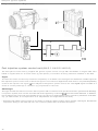
II I 111
Ignition systems - basic parameters
The ignition system control unit must be supplied with certain basic information in order to compute the frequency
or rate at w h ich HT ignition pulses must be delivered to the spark plugs, when (in relation to the position of the part icula r piston before TOG) each pulse must be generated and to which plug the pulse is to be delivered. The signals
required for this purpose are derived from the engine speed (A), engine load (B) and crankshaft position (G).
Speed information
A. The engine speed provides information on the number of ignition pulses which must be generated per unit of
time. The number of high-tension (HT) pulses delivered to the plugs must be increased as the engine speed rises.
The speed signal is the most vital piece of information supplied to the control unit. For example, the engine cannot
be started in this signal is unavailable.
The control unit also uses the engine speed to determine the point at which the ignition pulse must be delivered in
relation to the position of the piston before TOG. Ignition must take place earlier at higher speeds since the upward
and d ownward movement of the pistons is faster under these conditions. As a result, the time available for combustion of the fuel/air mixture is less and the timing must be advanced to ensure that the mixture is burned as completely as possible.
Load information
B. Except in turbocharged engines, the engine load varies with the vacuum in the intake manifold. At low loads, the
throttle is only partially open and the flow of induction air is low, resulting in a high vacuum. At higher loads, the
throttle opens wider and more air is supplied to the engine. Under these conditions, the vacuum in the manifold approaches closer to atmospheric pressure as the load is increased. It follows from this that a greater quantity of fuel/
air mixture is available for combustion as engine load increases and that the higher volume of gas produced reinforces the pressure due to compression. Since the rate of combustion is accelerated by higher gas compression, the
timing is retarded as engine load is increased. At low engine loads, on the other hand. the timing may be advanced
t o compensate for the lower rate of combustion and to improve fuel utilization.
Crankshaft position information
C. The crankshaft position (i.e. angle) provides information on the position of each piston in rela tion to TOC. This information is essential to the system control functions. which compute the timing continuously on this basis.
11
Group 28 Ignition systems
Desig n and function - General
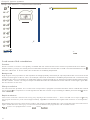
147081
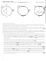
Fig. 1 'Hot' plug
Fig. 2 'Cold' plug
• Spark plugs : Use of the correct type of spark plug, correctly insta lled and replaced at the re commend ed intervals,
is essential to t he satisfactory operation of the ign it ion system. Assuming the engine to be in good co ndition , adherence to these recommendations will ensure maximum plug life, making the component one of the most reliable in the ignition system .
In this context, it may be of int erest to consider some of the demands imposed on the spark plugs and to discuss a
number of concept s.
- As the means used to ignite the mixture in the combustion chamber, the spark plug initiates the co mb ust ion process. The plugs are designed to supply up to approx. 25 sparks per second per cylinder at 6000 rlmin in a 4-cylinder
engine, from a high-tension source which, in the case of electronic ig nition systems, often operates at over 30 kV.
- Spark plugs must be capable of withstanding t he extremely rapid temperature and pressure flu ct u ations which occur in the combustion chamber. During the combustion process, the temperature rises at interval s t o a value of
perhaps 2500"C and the pressure to approx. 60bar (870 psi). Almost immediately, during the induction stroke, the plug
comes in contact with the cold, uncompressed fuel l air mixture, which is likely t o be at the same temperature as the
outside air.
- To ensure operation within the correct operating temperature range, spark plugs are made with different heat rat·
ings (o r ranges) for different engine types. If the operating temperature is too low (i.e. below about 400 C), the plug
w il l rapidly become coated with combustion residues . This type of fouling weakens the spark and causes the engine t o miss. On the other hand, if the operati ng temperature is t oo hig h (over approx . 1000~ C), the fuellair mixture
may be ignited by the incandescen t plug surfaces, initiating uncontrolled combust ion. Every engine manufacturer
specifies the appropriate heat rating on the basis of parameters such as specific engi ne output, probable runn ing
conditions and clima t ic conditions.
Q
- A plug with a high heat rating has a great er thermal retention capacity and conducts less heat away from the co m bustion chamber. This type is normally used on low-speed engines operating at relatively low com bustion temperatures. Plugs of t his type are also known as 'hot' plugs and are provided with a long insulator nose as shown in
Fig . 1.
- A spark plug with a low heat rating has a lower thermal retention capacity and conducts a greate r amount of heat
away from the combust ion chamber. This type is normally used on eng in es with high specific output s operating at
relat ively high combustion temperatures. Plugs of thi s type are also kn own as 'co ld' plugs and feature a short in·
sulator nose as shown in Fig . 2.
- Fitting a plug with the recommended heat rating will ensure that the correct working temperature is reached quickly w ithout t he risk of overheat ing. This also assumes that the t ight ening torque is within the specified limits, since
the thermal conductivity will be dependent on the degree of contact between the cylinder head and plug . The
spark gap should also be checked; an excessive gap will cause the engi ne to miss.
12
Group 28 Ignition systems
Design and function - General
A
2
1
'0·
0·1 0"
---=:J;~~
L-...l
-10
-20
-30
- ~O
- 50
°
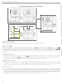
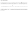
Contact-breaker versus electronic systems
Figure {AI shows the tim ing curve for a con tact-breaker ignition system, wh ile (BI illustrates the settings with wh ich
an electronic system is programmed, in the form of a three-dimensional map_In each case, both engine speed and
load are taken into account when determining the setting. However, in contrast with the electronic system, which
computes the timing, the con tact-breaker system controls it w ithin a specified range.
The timing must be con trolled to a high degree of accuracy to meet the demands of the modern engine for the cleanest possible exhau st emissions, maximum fuel economy and high performance under flu ctuating condi tions.
Neither may these requirements be permitted to vary, even following an extended period of driving .
Timing curve symbols
Both figures illustrate the manner in which the timing ang le {al varies w ith the engine speed (n) and the vacu um (pi
in the intake man ifo ld. The ang le (a) increases with speed ; in other words, ignition of the fuel/air mixture takes place
earlier as the speed rises. The angle also increases w ith the vacuum in the intake manifold i.e. as the engi ne load falls
and the fuel/air charge supplied to the engine becomes smaller.
Contact-breaker ignition systems
A . Contact -breaker ignition systems con trol the timing with the aid of a centrifugal governor (1) and a vacuum advance un it (2). (Being a speed-dependent device, the governor advances the ignition as the speed increases, while
the vacuum advance unit retards it as the engine load increases in response to the vacuum signal from the intake
manifold.) The two devices operate independently w ithin a tolerance band of approx. 2-4". Overall , this means that
the system controls the tim ing with in a tolerance range of approx. 4-8", since the setting is the sum of the angles indicated by the two curves. Furthermore, the variation wh ich results from wear of the breaker points affects the overall timing.
Electronic ignition systems :
B. The control unit (3) of an electron ic ignition system, by contrast, is programmed w ith a series of specific settings
for a number of defined speeds and engine loads. This means that the timing can be controlled to an accuracy as
high 8S 8 fraction of a degree and tha t each ignit ion pulse is del ivered as close as possible t o the optimum point.
(This high level of accuracy is achieved partly by the fact that the con trol unit interpolates between the programmed
speed and load points. In other words, it is capable of computing an intermediate setting.) Furthermore, the timing
can be computed over a wider range and is not restricted by the type of linear functions typical of a centrifugal governor.
The timing is computed with the aid of sensors wh ich determine the engine load and speed. Th is information is
transmitted electrically to the control unit electronics, in wh ich details o f a number of different speed and load combinations, together with the appropriate timing settings, are stored. Prior to each ignition pulse, the control unit computes a setting wh ich is perfectly matched to the engine running conditions prevailing at the precise instant.
Adjustments required by the various timing compensation fun ctions are added to the three-dimensional map.
13
Group 28 Ignition systems
Design and function - Components
c
B
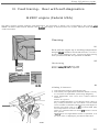
Components
Control unit
The control unit in an electronic ignition system continuously computes the optimum tim i ng based on information
supplied by the various sensors, which combine to provide the unit with an extremely accurate picture of engine running conditions. The con trol unit receives immediate notice of any change in the conditions under which the engine
is powering the car, enabling it to compute a new setting instantaneously. Once this has been completed (in an operation taking as little as a thousandth of a second!), the unit delivers an ignition pulse to the power stage.
The control unit consists of a number of electronic components. In simplified terms, these consist of four main elements - converter (A), memory (B), microprocessor (chip) (C) and output unit (D).
Converter
A. The converter (A) receives information from the sensors and converts the signals into digital (n umerical) form.
Some of the sensors supply analogue signals (such as the temperature-dependent change in resistance typical of a
temperature sensor), while the signal transmitted by others depends on whether or not a voltage is present (as in the
case of a throttle switch). The sensors may also transmit signals in the form of voltage pulses (like an inductive pickup) or a variable-frequency voltage (like a load signal vacuum converter). All of these electrical signals, whet her in
the form of a single, variable voltage or a series of voltage pulses, are converted into standard digital form by the
converter, the outputs from which are used by the microprocessor and memory.
Memory
B. All programs and pre-programmed values are stored in the memory (B), in which all possible values of parameters such as engine load and speed are available for immediate use by the microprocessor.
Micropro cessor
c. The microprocessor (C) receives the digital signals from the converter. Depending on the signal configuration, the
device selects the memory program which best meets the needs of the prevailing running conditions.
14
Group 28 Ignition systems
Design and function - Components
Output unit
D . The digital information supplied by the microprocessor is fed 10 the output unit (D) for conversion into the ignition
pu lses fed to th e power stage. (This may either be an integral part of t he control unit or a separate unit .)
Depend ing on th e program selected at t he particular instant, t he control unit determines the p oin t at which t he igni·
tion puls e must be delivered to t he power stage. The latt er con t rols the current in the primary winding of th e ignition
coil in response t o the signals from th e output unit.
Voltage stabilizer
The con trol unit is powered by a 12 V supply. However, since the bahery voltage is too high for the internal integ rat ed
circuits, a vol tag e stabilizer is used t o produce a stabilized 5 V supply for these.
• Engine speed limitation: A ll control units are programmed with some type of speed limiting function. On Bendix systems, the
conlrol unit normally commands the power stage to reduce the Ignition coil charging period. producing a weaker spark which
limils the engine output. On EZ-K systems, Ihe conlroi unit uses Ihe power slage 10 interrupl lhe spark 10 every second plug. The
speed limiting funct ion normally inlervenes at aboul 6200 r/min.
In t he case of cars equipped with F engines, the speed limiting function controlled by Ihe ignition syslem control unil is set to operate 81 a higher level than thaI controlled by its fuel system coun lerpart. T his prevents unburnl fuel from reaching Ihe catal yti c
converter, with the anendant risk of overheating.
• The control unit memory is programmed with a range of speed and load values. The unit improves the accuracy of control by interpolating between Ihese values, performing up to about 1ססoo computations per minute to ensure that optimum l iming is
maintained under all conditions. As many as 4000 individual settings may be computed as required.
• Built from components such as integrated circuits, transistors, diodes and capacItOrs, electronic components like the control unit
are relatively fragile . Since the electronics used in cars are exposed to such a diversity of operating conditions, they are subject to
particularly arduous demands. The equipment mUSI be designed to withstand vibrations. moisture, w ide temperature fluctu ations, variable voltages and other sources of outside interference (e.g. from rad iosl to which the electrical system is unavoidably
exposed.
• In th e case of certain internal fault s, the control unit regulates the ignition in accordance w ith a fixed. pre-programmed timing
curve.
• In Ihe absence of a load signal, Ihe con trol unit modifies the timing on the basis of the speed signals which it receives, and operates in accordance with the pre-programmed. full -load timing selling when the idling switch has opened.
• If the knock sensor signal is lost. the con l rol unit computes the timing setting on Ihe basis of a 'fail-safe' retardation of approx. 10".
• The control unil electronics must not be exposed to excessively h igh temperatures. For example, removal of the unit prior to the
completion of the stoving process during manufacture may result in its destruction . Because of its sensitivity to temperature, the
unit is normally installed in a location well protected from engine heal.
15
Group 28 Ignition systems
Design and function - Components
A
,
B
-
• JD
•
~[
c
i
J
-
'"
D
~
:oJ
JI
Ui
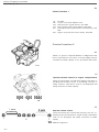
Control unit, power stage and ignition coil configurations
The control unit. power stage and ignition coil configuration may take one of four different forms.
As a general rule, the con trol unit delivers ignition pulses to the power stage (which controls the current in the pri.
mary w inding of the ignition coil) in response to signals from the various sensors and pick-ups. A high·tension voltage is induced in the secondary and fed to the distributor, wh ich delivers it to the appropriate spark plug, generating
a spark across the eleClrodes and igniting the fuel/ air mixture.
A. The control unit, power stage and ignition coil may all be separate components. This appl ies to EZ-K systems.
B. The con trol unit and power stage may be combined in a single unit. with a separate ignition coil. This applies to
TZ· 28H .
C. The power stage and ignition coil may be comb ined, with the control unit separate. This applies to Rex-I.
O. The control un it, power stage and ignition coil may comprise a single unit.
• Although the TZ -28H 'control unit' does incorporate a number of Ci rCUits additional to those used in EZ-K power slages, ils primary funct ion is closer 10 thaI of a power stage. and the term 'conlrol Unit' is somewhat misleading.
16
Group 28 Ignition systems
Design and function - Components
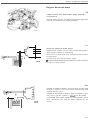
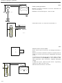
Power stage and ignition coil
Function of power stage
The power st age (1) functions as an electronic switch controlling the current in the ignition coil on command from
the control unit (31. (The illustration shows the components of an EZ-K system. In the Renix-F system, the power
stage is integral with the control unit, although the principle of operation is the same.I
The function of the power stage is analogous to that of the points in a mechanical ignition system, in that it alternately opens and closes the coil primary ground connection. Each time a cylinder fires, the power stage interrupts the
current in the primary, inducing a high-tension vol tage in the secondary.
Control signal
Once the control unit has computed a timing sett ing, based on the signals from the various sensors, th e value is converted into a control signal for the power stage. When this signal goes high (+5 VI, the power stage permit s the ignition coil to charge. When the signal again falls (10 0 Vl, the power stage interrupts the current in the ignition coil primary and the stored energy is released in the form of a high-tension pulse i n the secondary.
Constant charge
In the EZ-K and TZ-28H systems, the power stage incorporates a circuit which continuously monitors the primary
cu rrent used to charge the ignition coil and ensures that the charging current remains constant, regardless of engine
speed or battery voltage. This feature is designed to ensure that the ignition coil (2) receives a constant charge at all
times, irrespective of these parameters. As a result, the charge in the coil is always a maximum and the ignition voltage remains constan tly high.
Standing current protection
To avoid overheating of the ignition coil if the ignition is switched on with the engine at rest, the control unit incorporates a circuit which operates the standing current protection function via the power stage. Since the control
unit no longer receives signals from the Hall generator or speed pick-up (whichever is applicablel when the eng ine
has been stopped, it commands the power stage to interrupt the current in the primary winding of the coil.
Power stage cooling
Since operation of the power stage generates heat, the unit is mounted on a heat sink attached to the body. Secure
contact between the unit and heat sink is essential to ensure that the working temperature is maintained w ithin acceptable l imit s. The heat is generated by the power circuit which acts as the 'working' section of the power st age,
making the 'control' circuits vulnerable t o destruction. In systems in which the power stage is integral with the control unit, the former is mounted on the inside of the control unit frame to ensure adequate cooling.
Ignition coil
The primary winding of the ignition coil in an electronic ignition system (which generates extremely high voltages
up to a continuous 30 kV compared with an average of 15-18 kV in a conventional coil) has a relatively low resistance. Consequently, coils of this type are fitted with a plug (4) which opens to relieve the pressure in the unit in the
event of overheating and prevent deformation . NOTE: The plug muat be fitted with a protective cap in the case of a coil
installed vertically in the engine compartment.
17
Group 28 Ignition system s
Design and funct ion - Components
1
2
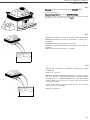
REX-I
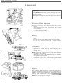
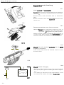
General
Since it is not technically practical to use the control unit to regulate the relatively h igh current in the ignition coil pri·
mary, this function is performed by a power stage which employs control signals from the control unit to vary both
the charging time of the coil and the instant at which it delivers it s high-tension pulse. The power stage opens and
closes the primary circuit, inducing a high-tension voltage in the secondary each time the primary cu rrent is interrup ted.
Construction
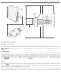
The power stage (1) and ignition coil (2) are assembled by means of screws (enabling the units to be replaced individually). The power st age receives control signals from the control unit (g re en lead) across th e two-pole centre connector (3) (which is also used to ground the signal). The three-pole connector (4) on the right suppl ies the power
stage and ignit ion coil wilh battery voltage, grounds the coil and supplies the rev counter with a signal. The connector (5) on the left is not used.
The power stage (1) incorporates the electrical circu its which control the primary current in the ignition coil. Mounted on a bracket in the eng ine compartment, the power stagelignition coil assembly is provided with a large contact
area with the suspension strut housing to ensure that the heat generated is d iSSipated.
The ignition coil (2) is of the conventional type w ith a pri mary and secondary wiring. The high-tension induced in the
secondary is fed to the distributor from terminal (6). As on most modern ignition systems, the HT voltage is of the
order of 30 kV.
Standing current protection
A functi on known as 'standing curren t protection' is provided 10 prevent overheati ng of th e ignit ion coil when the ignition is switch ed o n with the engine at rest. When the engine is st opped, the control unit receives no speed signals
-and del ivers a 'low' control signal to the power stage, which responds by opening the primary circui t of the coil.
18
Group 28 Ignition systems
Design and function - Components
A
147 081
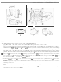
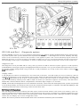
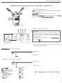
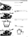
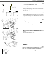
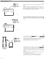
Distributor
Function
The function of the distributor is to conduct the high-tension pulse from the ignition coil to the appropriate spark
plug. A distributor fitted with a Hall generator also provides information on engine speed with the aid of the trigger
rotor driven by the distributor shaft.
Construction and variants
The distributor consists of a cap (1), rot or arm (2), shaft (3) and, in applicable cases, a Hall generat or (4) and trigger
rotor (5). (Older systems employ either contact breaker points or some form of pulse generat or.)
A. 'Vertical' distributors are driven by an intermediate shaft through bevel gearing.
B. 'Horizontal' distributors are driven directly from the camshaft, minimizing the play in the transmission mechanism. This, in turn, affords more accurate control of the timing in systems in which speed information is supplied
by a Hall generator.
700 series models from 1985 on (with the exception of the 740 with the B230A engine) are fitted with camshaftdriven units.
In the case of distributors which are not equipped with a Hall generator and, as a result, are fitted only with a rotor
arm, the timing cannot be varied by rotating the unit. In systems of this type, since crankshaft position signals are
supplied by an inductive p ick-up at the flywheel , only the position of the rotor in relation to the contacts in the cap is
altered by this procedure.
• The TZ-28H system employs a distributor. with a vacuum advance unit to supply engme load info rmation.
'9
Group 28 Ignition systems
Design and function - Speed and crankshaft position information
Speed and crankshaft position information
A
=:;:;)
N
8
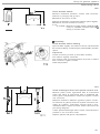
Hall generator
Function and location
The Hall generator (1) supplies the control uni t with information on engine speed and crankshaft position. The device is mounted inside the distributor cap.
Construction :
The generator is based on th e principle of the Halt effect, whereby the flow of current in a semiconductor is deflected
if the componen t is exposed to a magnetic field. This causes a potential difference (i .e. an excess of electro n s on one
side of the semiconductor and a deficiency on the other). producing a voltage known as the Hall vol t age. Following
amplification, this voltage is employed by the cont rol unit as a signal to con trol the timing .
The Hall generator (1) is a U-shaped element w ith an opening for the trigger rotor (2). The number of rotor vanes is
the same as the number of cylinders in the engine.
The generator consists of a Hall-Ie element (3) comprising a Hall effect detector and a transistor amplifier. A magnet
(4) with a three-pole connector (5) is located on the opposite side of the rotor t o the Hall· IC element . The connector
terminals are connected respectively to a 12 V supply (+), a 5 V reference signal from the control unit (01 and ground
(-)-
Signal
A . In th is position, the magnetic field is blocked by the trigger rotor vane and the Hall effect is absent. No voltage is
induced in the Halt-IC element and the ground connection rema ins open. As a result, a 5 V signal is present atterminal (01.
B. In this position, the rotor exposes the Hal l·IC element to the influence of the magnetic field and the resultant Hall
voltage is fed to the transistor amplifier. The 5 V signal at terminal (0) is then connected to ground across the H
terminal and the voltage at (0) falls to 0 V.
Thus, the signal from the Hall generator varies between 0 and 5 V in the form of a square-wave signal, the control
unit deriving its engine speed information from measurement of the duration of the alternating half waves. Thp.
crankshaft position signal is obtained by adjusting the basic sett ing of the distributor to coincide with the posit ive
flank of th e Hall generator signal (i.e. the half-wave generated when the rotor blocks the magnetic field) a few
cranksha ft degrees before TDC.
20
Group 28 Ignition systems
Design and function
5V
Js Ie I
I I
OV ,
A1
At
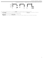
Speed and crankshah position information
,
A2
L
Signal increases from 0 to 5 V. Control unit starts to compule tim ing of ne)(l ignition pulse.
A2 Signal faits from 5 to 0 V. Conlro l unit commences ignition counldown and delivers ignition pulse as computed.
8
Posit ive flank . Hall element unaffected by magnetic field .
C
Negative flank. Hall element Influenced by magnetic field.
A Hall generalor is used on TZ· 28H (with a 12 V reference signal), EZ-l02K, EZ· 117K and EZ- 118K systems.
21
Group 28 Ignition systems
Design and function - Speed and crankshaft position information
Inductive speed/position pick-up
L .I-.-\ 4
'~7
090
Function and location
The purpose of the speed/position pick-up (1) is to supply the control unit (3) with information on engine speed and
crankshah position. The pick-u p is mounted close to the flywheel (2) (o r carrier plate on automatic models), the
periphery of which is provided with a series of drilled holes. The location of the pick-up is such that it is influ enced by
this con figuration of holes.
Construction
A. The pick-up (1) consists of a permanent magnet (4). a pole tip (5) which concentrates the magnetic field at the end
of the device and a coil (6). The magnet creates a magnetic field which varies in strength depending on whether a
hole or 'tooth ' is passing the tip.
Operation
An alternating voltage is induced in the pick-up coil when one of the projections or 'teeth ' on the fl ywheel passes the
tip. This variable signal is transmitted by a lead to the control unit.
In effect, therefore. the pick-up supplies the control unit with a unique al ternating vol t age - an elect rical ' picture' of
the flywhee l from which the unit can determine both the engine speed and crankshah position.
Signal
B. The frequency (7) of the signal (i.e. the period between two successive voltage peaks) is a measure of the engine
speed. To provide a reference signal for the crankshah position , one or more 'teeth' (one or two in the case of 4cylinder engines and three on 6-cylinder units) on the flywheel /carrier plate are made longer than th e others. The
con trol unit detects the crankshaft position by sensing the interruption in signal (8) which occurs as a long tooth
passes the pick-up. This reference signal is used to determine the top dead centre (TOC) position.
Group 28 Ignition systems
Design and fun ction - Speed and crankshaft position information
Advantages
Ignition systems employing inductive speed/position pick-ups (or pulse generators as they are also known) provide
more accurate speed and crankshaft position signals than th ose equipped w ith Hal l generators - due to the fact that
the former have fewer mechan ical components (which are invariably subject to some degree of play) and that a
crankshaft position signal is generated on each revolution of the shaft.
~
Inductive speed/position pick-ups are used on Reni)c -F. EZ-115K. EZ- t 16K and Rex-I systems.
• When work.ing in the vicinity of the flywheel. care must be taken to avoid striking the pick-up w ith tools or dismantled components. The accuracy and reliability of the signal is dependent on maintaining the gap I t :10.5 mmf between the tip and t he toothed
profile for which the device is designed. In addition. the pick-up must be mounted at right -angles to the profite.
~
The greatest care must be taken when replacing the flywheel/carrier plate if the component has been dismantled (e.g. as part of
gearbox replacement). On 4-cylinder engines. it is possible to replace the component in the wrong position. thereby altering the
timing.
• The timing will be altered by approx. 3" if the pick·up leads are reversed.
• AlthOllgh the magnitude of the induced voltage wilt increase with flywheel speed, the voltage regulator in the control unit ensures that the voltage supplied to the Ie circu its remains constant .
23
Group 28 Ignition systems
Design and fun ction - Speed and crankshaft position information
-
TOC
TOC
A
1-
I,
.A.
.~.
c·
B
'
c
Flywheel/ca rrier plate profiles
The above figures show the three different 'Ioothed' or drilled crankshaft/carrier plate profiles which are used. (The
profiles afe shown in section.) Unlike the starter motor ring gear, which is mounted on the flywheel. the profile used
for signal generation is usually an integral part of the component.
Volvo ignition systems are supplied mainly by two manufacturers - Bosch of Germany and Bendix, France. Among
other factors. this means that several different profiles must be used. while the method whereby the control unit detects and processes the inductive pick-up signals may also differ.
The electronic circuit (which may be likened to a frequency divider or 'multiplier' ) in which the signal is fi rst received
and processed, also varies in design. The frequency of the incoming voltage pulses is divided by a certain factor to
improve signal resolution. This, in t urn, means that the control unil can regulate t he timing in more precise steps, for
example, when re-advancing the timing after knock in a cylinder has been eliminated.
A. Ignition systems supplied by Bendix employ a type 4412 toothed profile. The figure 44 means t hat the flywheel is
provided with 44 drilled holes, and t he figure 2 that it has two 'long' teeth , each equal in leng th to two shorter
teeth. In other w ords, the profile is provided with 40 (44-2x2 ) short teeth and two long teeth . T he angular pitch between two adjacent short teeth (X O) is 8. 18° (360°/44 ). The two long teeth wh ich com prise the crank shaft position
referen ce points are located 180° apart (angle a). The con trol unit identifies TDC as th e p oi nt 90° after the passage
of a long tooth .
The type 44/2 profile is used on Aenix-F and Rex -I systems. In each case, the control unit applies a factor of 8.18 to
improve the signal resolution. This means th at it can adjust the timing in steps of 1.00 •
8 . Ignition systems supplied by Bosch for Volvo 4-cylinder engines feature a type 60/1 t oothed p rofile. This means
that the profile is provided with 60 drilled holes and with one 'long ' tooth of twice the length of a 'short' t ooth. In
other words, the profile is provided with 58 (60- 1x2) short teeth and one long tooth whic h represents the crankshaft position reference point . The angular p it ch between two adjacent short teeth lyO) is 6.0" (3000/60). The control unit identifies TDC as the point goo after the passage of the long t oot h.
The type 6011 toot hed profile is used on the EZ-116K system. This means that the control unit applies a factor of 16
to improve the resolution of the pick-up signal. In effect, the control unit can adjust the timing in steps of O.37se.
C. The EZ-1 15K ignition system for B 280 engines is designed for a flywheel with a type 6013 toothed profile. The profile is provided with 60 drilled holes and 3 'long' teeth, each of which is twice the length of a 'short ' tooth. In other
words, the profile is provided w ith 54 (60-3x2) short leeth and 3 long teeth as the crankshaft position reference
points. The angular p it ch between two adjacent short teeth (ZO) is 6.00 (360°/60). The three long teeth are located
120" apart la ngle cl. The control unit identifies TOC as the point 000 after the passage of a reference tooth.
The cont rol unit applies a factor of 16 t o im prove the resolution of the pick-up signal . In other words, the unit can
adjust the ti ming in steps of 0.375°.
24
Group 28 Ignition systems
Design and function - Engine (oad in formatio n
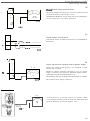
1.' 091
Engine load information
Intake manifold vacuum
The control unit is supplied with information on engine load through the "acuum line (1) from the intake manifold.
load information through vacuum line
When the engine load is low. the throttle (2l is only panially open and the vacuum in the manifold is high la pprox . 60
kPa ). As the engine load increases. the throttle opens furt her and the vacuum in the manifold gradually falls.
The ignition system may receive and process the load signal from the int ake manifold by one of three basic methods
in order t o adjust/comput e the timing sett in g.
Vacuum advance unit
A. On the TZ-28H system, the vacuum line is connected to a vacuum advance unit (3) on the distribu tor. The unit
houses a diaphragm, one side of which is open to the vacuum in the manifold and the other to atmosphere. A s
the vacuum increases (at low engine load with a partially-open thro ttle), the distributor plate is rotated to advance
the timing.
Electrical vacuum converter
B. The vacuum line on the Renix-F system is connected to a vacuum con"erter integral with the con trol unit. A lthough each vacuum converter is designed specifically for a particular system, the principle o f operation is the
same in all cases. The vacuum is applied t o one side of a spring-loaded diaphragm (4). the other side of which carries an iron core (5) mo"ing inside a coil (6). The coil is connected to an oscillator ci rcui t in the con trol unit, the frequency in wh ich varies w ith the position of the core and. as a result. is proportional to engine load.
Electronic pressure switch
C. On the EZ-1 18K system. the vacuum line IS connect ed to a pressu re switch (7) inside the control unit. The device
consists of a diaphragm. a magnet and a semiconductor element. The diaph rag m is actuated by the vacuum on
one side. while the other is attached to the magnet. The posit ion of the magnet influences the curren t flow in the
semiconducto r and. as a re sult. the value of the i nduced Hall voltage.
Thus. the voltage is proportional to th e posit ion of the magnet and, by extension . t o t he engine load. The load signal is received by the converter in the con trol unit and used to compute the t iming.
25
Group 28 Ignition systems
Design and fun ction
Engine load information
2 \.----t-rT
1
4
147093
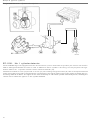
Fuel injection system control unit (LH-2.1. LH-2.2. LH-2.4)
The fuel syst em con t rol unit (1j supplies the ignition system control unit (2) with info rmation on engine load. Th is
based on signals from an air mass meter (3), the quant ity of induction air being used as a measure of th e load.
Signal
The air mass meter con t inuously measures the quant ity of air drawn int o the engine and delivers a variable signa l to
the injection system control unit, i n which the signal is convert ed int o digital fo rm and used to compu te th e quantity
of fuel to be inject ed. The signal is also relayed to the ignition syst em cont rol unit . The digital signal co nsists of a
series of current pulses (4 ) of a durati on (5) proportional to the load.
Advantages
Th is type of load info rmat ion is used in E2-K systems with LH-Jetronic fuel injection and Rex-I systems w ith the Regi na injecti on system, and is more accurate than that supplied by a vacuum line fr om the int ake manifo ld . In addition,
the air mass meter responds more quickly and is not subject to measurement erro rs caused by variations in air density. (In other words, it is independent of air temperature and heigh t above sea leveL)
• Should the fuel system control unit fail. for any reason. to supply the ignition system control unit with a load signal, the latter will
compu te the timing on the basis that max. load conditions prevail when the throttle has opened.
26
Group 28 Ignition systems
Design and function
Regina fuel injection
3
--
1
REGINA
REX-I
'<17520
REX-I
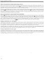
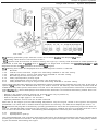
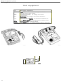
Regina fuel injection system
General
The i njection system con trol unit (1) suppl ies the ignition system control unit (2) with information on engine loadacting, in other words, as a 'sensor' for the latter.
The gas pressure in the cylinders duri ng the compression stroke will rise as a greater charge of fuel/ai r m ixture is
supplied to the engine, and the ignition system will retard the ti ming according as eng ine load increases.
S ign als
The electronic pressure sensor (3) and air temperature sensor (4) supply voltage signals to the Regi na control unit
Ill. Taken together, these signals provide a measure of engi ne load and are processed by the Regina control unit to
com pute the quantity of fuel t o be inject ed. Once the load signals have been converted into digital form (i.e. into
square-wave pulses), they are transmitted to the Rex-I control unit (2).
The digital signal consists of current pulses (5) of a duration (6) proportional to the engine load .
• Should the load signal from the Regina control unit be lost for any reason, the ignition system control unit w ill compute the t im ing on the basis of max. load conditions, provided that the id ling switch is not closed.
27
Group 28 Ignirion sysrems
Design and function - Compensation functions
Compensation functions
A
I?
F-::::
h
Il
"'"
B
©
~
c
1/
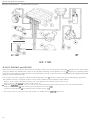
Theory of knock
Knock is caused by det onation of the fuel/air mixture in the combustion chamber.
What is knock7
Detonation may occur either aher las in A lar before (as in 51 the plug has delivered a spark. In either case, the mixture is ignited at two or more points in the chamber and combustion progresses from these points Ie). This results in
the simultaneous propagation of two or more flame fronts, causing abnormally rapid and uncontrolled combustion,
accompanied by an explosive rise in pressure which produces the typical, metallic sound known as 'pinking' or
'knock'.
' Compression' knock
A. In the case in which knock occurs aher the plug has delivered a spark. detonation is caused by the fact that the
flame front i nitiated by the spark. compresses and heats the unignited m ixture to the point at which detonation is
unavoidable. A relatively high eng ine load is requ ired to produce this type of knock.
'Glow ignition ' knock
B. In the type o f knock which occurs before the plug has delivered a spark, detonation of the mixture may be due to
incandescent carbon particles or gasket edges, fou led spark plugs or other areas of the combustion chamber
which absorb heat more easily. ITh is phenomenon is sometimes known as 'glow ignition'.)
Effects of knock
C. The abnormal pressure rise which accompanies knock subjects the piston, gudgeon pin. connecting rod, crankshah and bearings t o abnormally high mechanical stresses . Furthermore, the temperature ri se caused by th e phenomenon is so high that the cylinder wall . piston and spark plug may easily suffer damage, while the energy content of the fuel is poorly utilized. The unusual engine resonance caused by knock is detected by a knock sensor
mounted on the cylinder block. The sensor signal is transmitted to the control unit.
28
Group 28 Igni rion sysrems
Design and function - Compensation functions
Knock ' threshold '
Under certain condit ions, however, the combination of high perlormance and low fuel consumption demands that
the engine runs as close as possible t o the knock threshold. The closer the timmg curve to the threshold , Ihe higher
the efficiency of fuel utilization. In other words. the knock threshold is not a fixed limit, but varies depending on run ni ng conditions.
Methods of preventing knock
Knock may be prevented by retarding the ignition. Since detonation of the mixtu re occurs when the piston is closer
t o TOC, the pressure and temperature in the cylinder are t hereby lowered, reducing the r isk of detonation . Knock is
also p revented by enriching the mixture, which has the effect of reducing the combustion tem p erature.
• Knock may be caused by the fo llowing :
- Use of a fuel with an octane rating which is too low for the compression rat io of Ihe engine.
- Incorrect fue l/air ratio. If the mixture is too lean,the temperature In the combustion chamber will be h igh despite a conslant com·
pression ratio. A lean mixture may be due 10 a fac1 0r such as tow fuel pressure or air leaka ge into the induction system.
- Excessively high combustion temperature. Carbon deposits in Ihe combustion chamber WIll reduct! the rate of heat dissipation,
resulting in high temperature land creating the risk of glow IgnitIon). DefiCient cooling (due, for example, to a fau lty water pump,
radiator or thermostat, or to rustnime deposits m the cooling passages). Will have the $time effect.
- Incorrect or worn spark plugs. The fisk of detonation will be greatly mcreased if the plug IS o f the wrong type ILe. if the heat rating
is incorrectl or is it IS fouled .
- Faulty timing. The resistance to knock Will be impaired if ignition takes place too early. since the cylinder pressure and temperature w ill be higher under these conditions.
- A sudden increase in engine speed. What is known as 'transitional" knock w ill occur if the engine speed and load are suddenly in·
creased. If the engine is running under normal conditions of speed and load {with the timing fairly weI! advanced), sudden depression of the accelerator will produce an instantaneous increase in the quantity of mixture admitted before the system has had
time to adjust the timing accordingly. For a brief period, therefore. the timing will be too advanced for the amount of mixture in
the cylinders. lOne of the fun ct ions with which the control unit is programmed limits the scope of timing adjustment to a specified number of degrees per cran kshaft revolUhon .1
29
Group 28 Ignition systems
Design and function - Compensation functions
B
c
D
1U095
Knock sensor
Function
The knock sensor (1) is used to detect engine knock, enabling t he con trol unit (2) t o take the appropriate action by re tard ing the ignition.
Constructi on
The knock sensor (see p icture C) consist s of a casing {3) housing a piezoelectric crystal (4) mounted on a threaded
sleeve (5) between two connector strips (6). One side of the assembly is fi tted with a damping weigh t (7) and spring
washer (8) secured by a nut (9).
Operation
Mounted on the cyl inder block, the sensor detects the vibration caused by knock. Since the device employs a piezoelectric crysta l lin which a potential gradient is set up when the material is subjected to strain), the sensor develops
its 'own' signal. The vibrations caused by knock produce an instantaneous pressure on the bottom of the sensor,
wh ich responds by generating an output voltage.
Signal
The signal delivered by the piezoelectric crystal consists of a con tinuous, variable voltage of a frequency corresponding to the engine vibrations. The signal is fed to the control unit which computes a mean or ' reference' value.
Sensing of signals
The control unit is programmed specifically to detect signals of the frequency generated by knock {approx. 7.5 kHz).
The unit is provided wi th a 'measurement window' - in effect, a specific range of cranksha ft angles wi th in w h ich the
unit is 'open' to receive signals from the knock sensor (approx. 150 before TOC to approx. 550 after TOC). Immedia tely
on detecting knock in a cylinder, the device generates a signal which deviates significantly from the compu ted 'reference' signal. This is interpreted by the control unit as confirmation that knock has occurred. After an interval of th ree
ignition pulses (in the case of 4-cylinder engines), the con trol unit ret ards the ignition, thereby correcti ng the condition in the individual cylinder concerned.
30
Group 28 Ignition systems
Design and function - Compensation functio ns
B
c
D
Variants
The three different types of knock sensor used are illustrated above.
Type (B) is used on EZ-102K. and on EZ-117K and EZ-118K systems from 1985 to 1986.
Type (C) is used on EZ-116K systems from 1987 on, as well as on EZ-l17K and EZ-118K, and on Rex-I from 1989 on.
A refinement of type (B ), this variant is fined with a sleeve (5) which ensures that the mounting force is less easily
transmitted to th e piezoelectric crysta l, making the unit less sensitive to the effect of the tight ening torque.
Type (0) is used on the EZ-11 5K system on the B 280 eng ine. which is fitted with a knock sensor for each bank of
cylinders. The only difference between th is variant and type (C) is that the connection lead is integ ral w ith the unit.
• Type IC) and lDl sensors are less sensitive to tighten ing torque than earlier lypes. The design permits the torque to vary from 15
to 25 Nm '1 1- 18 ft.lb) w ithout any adverse effect on the performance of Ihe device. Although production of type 181 was d iscontinued in 1986, it is fu lly interchangeable w ilh type ICI. Particular care muSI be taken when fining the older type 01 sensor; a
torq ue wrench must be used to l ighten Ihe device in position.
• Since the ignition may be retarded in each individual cylinder in the evenl of knock. the tIming In each may vary by as much as approx. 10--15· , Apart from the fact that knock control is inherently a major advantage. the facility of eliminating it 10 an individual
cylinde r means Ihat fue l utilization can be maximized in relation to the knock Ihreshold in each. ThIS is importanl since conditio ns
in the various cylinders may differ somewhat in terms of combustion temperature, fuel residue deposits on cylinder walls. injector design, and so on.
• Relardation of the ignition in each individual cylinder is a feature of all systems equipped w ith knock sensors dealt with in th is
manual.
• Should the signals from the knock sensor be lost for any reason . most of the control units w ill retard the ignition by a preprogrammed 'fail-safe' value 01 approx. let.
31
Group 28 Ignition systems
Design and function - Compensation functions
Q'.
Q_1°
0'_2 0
Q_3°
_3·
0'_4 0
Q_S o
,..---t
~.
,.r---
0' _60
0' _7 0
r---
0' _6 0
S-'
O' _gO
0' _16 oT
-16 o '-C
r---
,.---.1 >-..J
..1
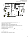
Knock control
The kno ck sensor moniiors the combust ion process continuo usly. If knock occurs, the device delivers a special sig.
nal to the control unit, which takes corrective act ion by retarding the ignition i~ the cylinder affected.
Knock control characteristic
The principle of knock control is more o r less the same in the case of all systems equipped with knock sensors. (AI·
though the kn ock control characteristic shown is that for the EZ·115K system, the description is generally applicable.) The vertical coordina te shows the ignition setting in degrees in relation to the basic timing (i ndicated here by
the angle <xl, while the horizontal coordinate is the time scale (which normally varies wi th eng ine speed).
Stepped control
The control unit continuously compu t es the optimum t iming on the basis of the running conditions. On detecting
knock, the unit retards the ignition by a step of a few degrees (2_3° depending on the system) i n the cylinder affected.
If the phenomenon persists, the setting is retarded by a further step, and so on until the condi tion has been corrected. The maximum retardation in relation to the basic t iming is approx. 10-16° in th e case of EZ-K systems.
Ae-advance following correction of knock
After knock has been eliminated, th e control unit maintains the retarded setting for a specified number of engine revo lutions, depending on the speed (applies to EZ-K systems). before re-advancing the ignit ion in small steps (0.1-1 °),
either until the original characteristic has been restored or until the engine again starts to knock.
• The maximum retardation must not deviate excessively from the basic setting if an excessive rise in exhaust gas temperature is to
be avoided. Informat ion on engine speed andfor load is also essential to enable the cont rol unit to impose the maximum retardation, if necessary.
32
Group 28 Ignition systems
Design and function - Compensation functions
b
Q'-b
a
Q'-2b
·••,,
,
I
I
~
~ ~ _
..
__ ...
,.. ..
L~----1
,,
,,
,,
,
I
Q'-3b
~
__ ...
L-~~--i
~-~-l
r
><~--~_
..
\-;--'47 ' 00
Timing compensation applied by different ignition systems to correct knock
Fig. 3: '" = basic timing as computed
a = max. knock-controlled retardation
b = knock retardation step
c ~ re-advance step
d = re-advance interval
The following is a summary of the compensation values applied by the various systems in the event of knock:
EZ-l02K:
EZ-l17K:
EZ-118K:
Max. knock-controlled retardation:
Knock retardation step:
Re-advance step:
Re-advance interval:
Max. knock~con trolled retardation:
Knock retardation step:
Re -advance step:
Re-advance interval:
0.35'
Specified number of engine
revolutions depending on speed
13" (B230F); 9.8"' {B230FT)
2.8'
0.37'
Specified number of engine
revolutions depending on speed
lvalues for B230K, 1985-86; 8230E and B200E respectivelyl
Max. knock-controlled retardation:
Knock retardation step:
Re-advance step:
Re-advance interval:
revolutions depending on speed
EZ- 115K:
Max. knock-controlled retardation:
Knock retardation step:
Re-advance step:
Re-advance interval:
EZ-116K:
Max. knock-controlled retardation :
Knock retardation step:
Re-advance step:
Re-advance interval:
Rex-I :
9.8'
2.8'
Max. knock-eontrolled retardation:
Knock retardation step:
Re-advance step :
Re-advance interval:
15",16", 9.8"',12.6"
2.8"', 2.8"'-8.7" (depending
on speed!. 2.8", 2.8"'
0.35" in all cases
Specified number of engine
11-15" depending on variant
3"
0.37"
Specified number of engine
revolutions depending on speed
,.2.6" at n < 4895 r/min and
2.3" at n > 4895 rfmin
0.375"
Specified number of engine
revolutions depending on speed
15"
-3" at n > 4895 r/min
,"
Specified number of engine
revolutions depending on speed
33
Group 28 Ignition systems
Design and fun ction - Compensation fu nctions
Q' 0
0' _1 0
0' _2 0
0' _30
0' 0
41
_3°
0' -5 0
0' _6 0
_7 0
a _so
.a
Ii"
I
a
a _4°
Q'
0
b
#:
#: .....
D
""
I' ... 011
I
I
-6ot,
0' _9 0
O'-15°{
REX-I
Ii"
I
D
. . . . 011
ICI CI
a
all
I
c!J
•
co
&' ... I!I
p- -
D
D
I
I
I
-9011 a _ • III II!
*~
.co'"
r
I
.. alllcd
-•
D
1. 1011
Rex-I
On the Rex-I system, the program functions which con trol the tendency of the engine to knock are somewhat different to those in the EZ-K systems. The differences are described in the following pages.
Knock characteristic
The figure shows the 'no rmal ' ignition setting (0.) assuming, in th is case, that speed and load are consta nt (hence the
extremely simplified 'straight' yellow line). The vertical axis ind icates the ext ent to wh ich th e timing has been ret arded in relation t o the normal sett ing, 0. The horizontal axis indicates the tim e, as defined by a ce rtain nu mber of en ·
gine revolutions. Knock ret ard ation is illustrated by the downward steps (red) and re·advance by the small er upward
steps upwards (blue). The maximum retardation is 15°, here denoted by '0 - 15'.
Knock-controlled retardation
When the engine is running, the control unit computes t he optimum ignition timing on the basis of speed and load
signals. The occurrence of knock in a cylinder is detected by the control unit, wh ich retards the ignition by a step of 3"
in the cylinder in question . If the phenomenon persists, the control unit retards the ignition by a further step of 3°
In -6") and so on, until knock is eliminated.
Ae-advance at different rates
Re-advance of the ignition to the normal setting (a), or until knock again occurs, takes place at d ifferent rates depending on engine speed. However, the steps are equal in magnitude in all cases, representing an advance of 1° at a t ime.
Once the timing has been retarded (to a -JO or morel (a), the succeeding re-advance steps (b ) are performed twice as
fast. Thus, the interva l 'a' in the figure is twice as long as 'b '.
At high engi ne speed, the interval 'a' duri ng which the tim ing is retarded (to a -3" or more) is relatively long . (The interval is equ ivalent to approx. 80 revolutions at an engine speed of about 6000 rI m in).
At low eng ine speed, the corresponding interval is about half that at h igh speed lapprox. 35 revolutions at an engine
speed of about 1000 rlmin }.
The re -advance rates vary across the speed range, becom ing slower as engine speed increa ses.
34
Group 28 ignition systems
Design and function
Compensatio n fun ctions
Reason for different re-advance rates
'Faster' re-advance rates are possible in the lower speed ranges since ign ition then takes place when the piston is
closer t o TDC and the risk of knock is, consequently, lower. Fast re-advance is more advantageous since it serves t o
increase the mean value of the timing angle. (As al ready described, advancing the t i m ing point im proves t he efficiency of fuel utilization .)
'Slower' re -advance rates are chosen at higher speeds since ignition then t akes place relat ively early as the piston
moves upwards towards Toe (and the attendant risk of knock is greater ). Increasing the rat e of re-advance under
t hese condi tions wou ld g reatly inc rea se t he likelihood of recurring knock .
• EZ-K systems employ more or less the same method of varying the re-advance rates following knock-controlled retardation.
35
Group 28 Ignition systems
Design and functio n - Compensation functions
(lI 0
Q'°'F = == ==
_8°
Q'-15°{
_
REX-I
147 DIll
Load-controlled retardation
Function
Since a sudden increase in load greatly inc reases the risk of knock, the control un it incorporates a fun ct io n which retards the tim ing sharply for a brief period under these condit ions. The fun ction of load-controlled ret ardation is to reduce the likeli hood of knock when the accelerator is suddenly depressed.
Backgro und
High engine load (equivalent to the injection of a la rge quantity of mixture) is a prerequisite to the occurrence of the
more com mon types of knock. Thus, for example, when the accelerator is suddenly depressed, the control unit may
be unab le (by virtue of it s design) to retard the ignition quickly enough by an amount equivalent to the load increase.
For th is reason , certain cars may be su bject to what is known as 'transitional ' knock if driven in too high a gear with
the accelerat or to the fl oor.
Sharp retardation
To overcome this problem , the con trol unit incorporates a program -co ntrolled fun ction wh ich retards the normal
timing (oc) by SO in response to a load signallfrom the fuel control unit) ind icating a sudden pressure drop in the intake manifold.
Rapid re·advance
The con trol unit t hen restores the timing very rapidly to the normal value, 0.. This is carried out in steps of 1" every
five engine revolutions (both values approximate). regardless of whether the higher load condi tion is o f longer duration.
Should the rapid pressure drop be followed by full open ing of the throttle, the con trol unit will have sufficient time t o
again retard the basic timing by a sufficient amount w ithout any significant ri sk of fu rther knock.
• EZ-K systems 8re equipped with 8 similar knock control function.
36
Group 28 Ignition systems
Design and function
r--I
Iol
aO
0' _1 0
I'
#
0' _2 0
0' _3 0
0' _4 0
_4·
a
0' _5 0
0' _6 0
Q' _7 0
lIIIlf ,.
, --
@
:r:•••
_1 ·
""
Compensation functions
•
•
••
•
-4. . . . .
~:
•• ••
-7oa. •••
REX-I
Adaptive timing retardation
Background/funct ion
If normal eng ine load is exceeded for longer than usual (for example, when the car is driven up a long i ncl ine, is pulling a trailer or is running on low -g rade fuel), knock-controlled retardation wi ll intervene more often. The adaptive retardation function, on the other hand, retards the timing by a small amount for a longer period to redu ce the r isk of
knock at specific combina tions of engine speed and load .
M eaning roughly 'self-learning', the term 'adaptive' is used to describe the fact th at the con trol unit, after a time,
'tearns' that running condit io ns have changed more or less permanently, The fun ction is applied individu ally to each
cylinder.
Conditions
On the upper curve (green), the upper position on the vertical axis represents a combina tion of engine speed and
load which experience has shown to be particularly susceptible to knock. The horizontal axis is the t ime scale, calibrated in this case in tens of minutes.
If the control unit detects that the load/speed increase is of a 'permanent' nature (Le. that it has lasted for a specific
time ), it will adopt the adaptive retardation mode when knock occurs.
Activat ion
The lower curve illustrates the pract ical effect of adaptive timi ng retardation. Representing a period of approx, 10
minutes during wh ich the function is activated, interval lal is termed the 'active adaptive zone',
If the control unit detects that the speedlload increase is of a permanent nature before the adaptive zone is reached,
the basic timing will be ret arded by 1°, The function is activated in the event of knock i.e. the basic tim ing is retarded
as indicated by the start of interval (a) in t he figure.
In this case, the tim ing is retarded by 4° (to -4°, o r 1° more than under 'normal' kn ock conditions). following which it
is re -advanced in the usual manner (at a rate which varies w ith engine speed) to 1° below 'the basic setting' (0. _' 0).
37
Group 28 Ignition systems
Design and function - Compensation functions
If the load temporarily reverts to normal (b) during the adaptive retardation period (e.g. if the trailer is uncoupled or
the road becomes downhill), the timi ng will be returned to the basic setting (a). If engine speed and load subsequently change (within the 10-mi nute period) so that cond itions once more fall within the knock-sensitive zone (c),
the control unit will agai n automatically retard the timing by 1 ~ without the occurrence of knock.
If knock persists despite the intervention of the adaptive retardation function, the timi ng w i ll be retarded as usual (as
indicated by the dashed downward steps) i.e. by 3" each time kno ck occurs.
The control unit always leaves the adaptive mode (at the end of interval (a)) after a predetermined interval (approx.
10 mini regardless of load. If the load remains high, a new adaptive period w ill commence if knock recurs and the
cycle will be repeated from the start of interval (a).
Advantages
On average, this mode of knock control permits a more advanced timing setting to be used - an advantage in terms
of combus tion, fuel economy, and so on - due t o the fact that fewer knock -controlled retardation operations are required when the function is activated. Stated in simple terms, knock is prevented by detecting the increased risk of
the phenomenon.
38
Group 28 Ignition systems
Design and function
Compensation functions
147 101
Knock-controlled fuel enrichment
Knock-control led fuel enrichment means that the injector opening period is extended to enrich the fuel/air mixture,
reducing the combustion temperature and brin ging the uncontrolled combustion under control. The function is activated if the ignit ion system control unit detects that knock is occurring in all cylinders above a certain threshold
value.
On receiving a signal from the knock sensor (2) and having established that knock is present in all cylinders, the control unit (1) connects a terminal on the fuel injection system control unit (3) to ground, causing the latter to transmit a
signal to the injectors (4) to extend the opening period.
Knock-controlled fuel enrichment is a feature of EZ-117K o n the B230FT engine, and of all variants of EZ-11SK and
EZ-1 16K.
* The function is activated only w ithin a certain speed and load range, in addition to which a certain average knock -controlled retardation must already have been applied in all cylinders. The following conditions are requ ired for the intervention of the knockcontrolled fuel enrichment function on the various ignition systems/engines:
- EZ-l17K on B230FT: 6" retardation in all cylinders in response to knock detector signals.
- EZ-115K on B280E/F: Retardation of at least 10° in all cylinders in response to knock detector signals at engine speeds above
3800 r/min and above a certain minimum load.
- EZ-116K on 8 234 F: Retardation of at least 3--40 in all cylinders in response to knock detector signals at engine speeds above 3800
r/min and above a certain minimum load.
39
Group 28 Ignitio n systems
Design and function - Compensation functions
Throttle switchlidling (air control) switch
Function and location
The throttle switch (1) supplies a signal to the ignition system control unit when the throttle is fully closed. The signal
is u sed t o enable th e con t rol unit (4) to select a tim ing setting which is suit able for idli ng and engi ne braking cond itions. The throttle swit ch detects the throttle position (2) by measuring the rotation of the spindle (3).
Signal
Thro ttle closure (for example under idling and engine braking condition sJ grounds one o f the sw it ch terminals, allowing a cu rrent to flow from one of the term inals on the con trol unit. The ground current is interpreted by the control unit to determine, on the basis of engine speed information, whether the conditions are those of idling or engine
braking.
Idling
At speeds close to idling , the signal causes the control unit to adopt a 'fi xed ' ignition setting in accordance with the
idling program. Since the engine is not required to develop a specific power when idling , the timing is determined
ma inly on the basis of maxi mum comfort. Th is means that the setti ng is well retarded (between approx. 10" and 16"
before ToC) to minimize the peak (i.e. maximum) pressure in the combustion chamber during the combustion
phase, ensuring smooth , steady running.
Engine braking
Since the speed is h igher under engine braking co nditions, the control unit timing cha ra ct eristic is speed -dependent
only. In general , t he cha racteristic represent s an o ptimum compromise between th e lowest possi ble emissions and
mi ni mum fuel consumpt io n.
(M ost of the elect ronic fuel i njection sy stems used fea ture a fuel cu t -off fu nction which intervenes und er engine b raking cond itions. In t his case, the fuel system control unit is also su pplied with a fUlly-closed throttle signal and keeps
the injectors fully closed under these condi tions.)
Throttle switch types
A. Practically all fue l·injected models in the 700 series are fined with the type of throttle switch illustrated. The
sw itch is mounted on the throttle spindle (3J, which actuates a cam plate (5) and an arm (6). The arm operates a
microswitch (7) which closes to g round a terminal in the connector (8).
(Apart from supplying a signal to the control unit when the throttle is closed, the type of switch used on some engine variants incorporates a set of full·load contacts (9) wh ich close when the throttle is fully open. In th is case, a
full -load signal is fed to the fuel system control unit, instructing it to extend the injector opening period. However,
this feature is not used on turbocharged engines.)
C. The EZ-118K system employs an idling switch (12) mounted on the throttle cable pulley to indicate w hen the
throttle is fully closed. The con trol units use the signal to establish a com fortable t iming setting when idling and
to activate the fue l cu t -off function under engine braking conditions. The EZ-118K control unit also uses the signal
as a condi tion for advancing the timing for idl ing speed compensa tion when a drive position is selected on an
aut omatic model or the AC compressor is switched in.
* It is extremely imponant that the throttle switCh be correctly adjusted before checking the timing, to ensure that the idling setting
is correctly measured.
* Electronic ignition systems not equipped with a throttle switch or idling (air control) switch are supplied with info rmation on
idling conditions in the form of a sig nal representing the vacuum in the intake manifold.
40
Group 28 Ignition s ystem s
Design and function - Compensation functions
[]
3
Temperature sensor
Function and location
The control unit (1) compensates the timing for engine temperature with the aid of the temperature sensor (2). This
function is used to adjust the timing at temperatures deviating from the normal operating range (i.e. outside approx.
8O"C t o 1000C). The temperature sensor is normally mounted in the cylinder head and is completely immersed in the
coolant.
Construction
The temperature sensor consis ts of a connector (3) and a body (4) provided with a male thread and enclosing one or
two temperature-sensitive resistors (5) w ith a negative temperature coefficient (NTC). On most fuel -inject ed engines,
the device is equipped with two resistors, one of which is connected to the fuel syst em control unit to provide a fuel
enrichment signal when the engine is cold and the o ther to the ignition system control unit. (Twin-resistor temperature sensors are normally grounded to the cylinder block, while the single-resistor type is grounded through the
control unit.)
Signal
The resistance of the temperature sensor varies in direct propon ion to the coolant temperature. falling as the temperature rises. Since the control unit continuously supplies the sensor w ith a constant current, the va riat ion in resistance is reflected by the voltage drop across the device. enabling the control unit t o determine when the various temperat ure-dependent timing adjustments must be made.
Before considering the beneficial effects of tempera ture compensation on t he tim ing, some effort should be made t o
gain an understanding of th e effects of variations in t iming on the cyl inder, exhaust gas and coolan t temperatures.
41
Group 28 Ignition systems
Design and fu nction
Compensation functions
Theory of temperature-compensated timing advance
Advancing the ignition timing increases the cylinder temperature while reducing the exhaust gas temperature. Under certain conditions, this also yields a reduction in coolan t temperature. The higher cylinder temperature is due to
the higher pressure of the fuel/air mixture as it is ignited, while the lower exhaust gas temperature is due to the relatively late scavenging of the gases at the end of the combustion process.
The lower coolant temperature achieved by advancing the timing when idling is partly due to the fact that the setting
is already well retarded and that a relatively high proportion of the fuel does not. as a result. produce mechanical
work, the energy being dissipated in the form of heat losses. Advancing the timing under these conditions greatl y
improves the efficiency of combustion, increasing the amount of energy converted into mechanical work and reducing the amount of heat discharged to the coolant.
Theory of temperature-compensated timing retardation
Although it reduces the cyl inder temperature, retarding the ignition increases the exhaust gas and coolant temperatures. The lower cylinder temperature is due to the reduced pressure of the mixture when it is ignited, while the rise
in exhaust gas t emperature is due to scavenging of the gases closer to the exhaust valve opening point. The higher
coolant temperature is attributable to the fact that less of the energy content of the fuel is converted into mechanical
work, a higher proportion being dissipated in t he form of thermal losses. As a result, a higher quantity of heat is
transferred more quickly to the cyl i nder wall, exhaust gas port, intake manifold and coolant passages.
Timing compensation on cold engine
Temperature compensation of the timing on a cold engine usually i nvolves advancing the ti ming to shorten the
warm-up period. However, temperature-controlled functions which retard the timing in a cold engine are also used.
One of the effects of this is to bring the catalytic converter up to working temperature more quickly, while another is
to increase the coolant temperature, accelerat ing the defrosting action of the cl imate con t rol system.
The temperature sensor signals may also be used by the control unit to determine when the knock sensor signal
should be switched in. Blocking this signal when the engine is cold ensures that the control unit is unaffected by spurious signals caused by the mechanical noise typically emilled by the engine as it warms up.
Timing compensation on hot engine
Temperature compensation of the timing on a hot engine means advancing the timing to reduce the coolant temperature. This prevents the engine from boiling (although the cooling water will not begin to boil while the temperature
is below approx. 120-125°C, due to the fact that the system is pressurized). The timing advance is normally applied
only when idling, since t he setting is normally fairly retarded under these conditions.
•
42
Group 28 Ignition systems
Design and function - System descriptions
m
5
n
TSZ
B28AJEJF
TSZ is a type of electronic ignition system in which an inductive pulse generator performs the function of the contact
points. (Roughly translated, the abbreviation TSZ means 'Transistorized coil ignition'.) The pulse generator transmits
information t o a 'control unit' which controls the charging period of the ignition coil. The system also incorporates a
centrifugal generator and a ballast resistor. The variant used on 6-cylinder engines (8 28A1E/Fl is designated TSZ·4
and is used on 1982-86 700s.
43
Group 28 Ignition systems
Design and function - System descriptions
30
5
o
o
o
o
15
3
+
210
6
0
5
6
3
4
15
2
1
0
TZ·28H
1
TZ-28H
B19E1ET, B23E, B230A
The 'control unit' (210) consists of a number of electronic circuits operating a power circuit which controls the primary current in the ignition coil. The 'control unit' interrupts the current on receipt of an ignition pulse from the Hall
generator in the distributor (5) and ensures that the ignition coil is fully cha rged between pu lses. The 'co ntrol unit'
also feature s a stand ing current cu t -off fun ction wh ich prevents overheating of the ignition coil by interrupting the
cu rrent if no speed signals are present .
'Control unit' connections :
1.
2.
3.
4.
5.
6.
44
Controls ignition coil (4) primary current
Ground terminal
Hall generator ground terminal
Power supply (12 V)
Hall generator power supply (12 VI
Receives engine speed and crankshaft position signals from Hall generator
Group 28 Ig nition s ystems
Design and function
System descriptions
3
\
4
UJ 105
RENIX - F
RENIX-F
B200K
(The above illustration and the following text are based on the B 200 K engine used in the 740)
The system consist s of an electronic control u nit (1) which is supplied with engine speed and crankshaft position signals by an inductive speed/position pick-up !2). Th e pick-up detects the passage of a number of 'teeth' on the flywheel (3). The control unit is also suppli ed with information on eng in e load through a vacuum l ine (4) co nnected to
the intake manifold, the pressure in which actuates a vacuum advance unit (5) integral with the unit.
The speed and load signals are processed by th e control unit electronics and compa red with the timing settings
stored in the memory. Having used the information to compute the optimum timing, the unit transmi ts control signals t o an integral power stage wh ich makes and breaks the current in the primary w i nding of the ignition coil!6) at
the correct instant, generatin g a high-tension current in the secondary. The HT pulse is fed to the distribu t or (7) for
del ivery t o the appropriate spark plug (81.
Apart from the rotor, the distri butor con tains no mechanical or electronic components, its sole funct ion being to distribute the high-tension current to the correct plug .
• At idling speeds of less than 1000 rIm in, the control unit advances the timing by 5- to prevent a drop in speed when the AC system
is switched on or when a drive position is selected on an automatic model.
45
Group 28 Ignition systems
Design and function - System descriptions
,
so
IS
000
2
86
'-
3 • ~
, '
'7
0
;
5
'
t,
RENIX-F
147106
Control unit connections
1.
2.
3.
4.
5.
6.
7.
8.
9.
46
Supplies speed signals to rev counter (86).
Connects con trol unit (406) to ground.
Receives supply from battery (1) via ignition switch {21.
Receives engine speed and crankshaft position signals from speed/position pick-up (407 ).
Receives engine speed and cran kshaft position signals from speed/position pick-up (407).
Receives signal from idling advance relay (293) on ca rs with automatic transmission and/or AC.
Spare.
Spare.
Connected to radio interference suppression capacitor (D).
Group 28 Ignition systems
Design and function - System descriptions
1
0r.===:::::::==
10
-1----\ 9
~t~======='J
4
7
EZ - 102K
EZ-102K
823FT
(760,1984 with 823FT)
The sensors supply the control unit (1) with a series of signals which descri be the engine running conditions. The
control unit uses the signals to compute the optimum timing and transmits the necessary ignition pulses to the
power stage (2), which makes and breaks the current in the primary winding of the ignition coil (3). The high tension current thereby induced in the secondary winding is delivered to the appropriate spark plug (4) by the
distributor (5).
The timing is computed by the control unit on the basis of the following i nformation :
- The Hall generator in the distributor (5) supplies a signal indicating the engine speed and crankshaft position.
- The engine load signal is supplied by the LH-2.1 in jection system control unit (9) which, in turn , is supplied with a
load signal by the air mass meter (10),
- Any tendency of the engine to run hot is indicated by a thermostat (8). (The throttle must be closed and the engine
temperature must be above 103°C before the control unit advances the timing . Under these conditions, the thermostat will close, and the control unit will both advance the setting by 13° and switch in the electric radiator fan. )
- Engine knock is indicated by the knock sensor (7),
- Throttle closure is indicated by the throttle switch (6).
47
Group 28 Ignition systems
Design and function
System descriptions
@), r-----,~.. ~'r--------i
"
,,~,
f--------.L----,,---.:.--..,
~F~~~~::::=
,
I------j.
!'!===,--j
~
~
,----1"
853
214
4
60
"
EZ - 102K
Control unit connections
1.
2.
4.
5.
6.
8.
9.
10.
11 .
12.
13.
14.
15.
Receives power from battery (1) l h rough ignition switch (2).
Transm its speed signal to fuel system control unit (217)
Connected to ground by throttle switch (198) when throttle is closed.
Transmits fault signals t o test terminal (267) when fault tracing with test diode.
Receives engine speed and crankshaft position signal from Hall generator in distributor (5).
Receives signal from knock sensor (218).
Transm its ignition pulses to power stage (133).
Receives 12 V supply on closure of thermostat (224).
Grounds con lrol unit (260).
Grounds screen of lead from Hall generator in distributor (5).
Supplies power t o Hall generator in distributor (5).
Receives load signal from fuel system control unit (217).
Grounds screen of knock sensor (218) lead.
Power stage connections
1.
2.
3.
4.
5.
48
Controls current in ignition coil (4) primary w inding.
Grounded.
Grounds screen of lead connected t o termina l 5.
Receives power from battery (1) across ignition switch (2).
Receives ignition pulses from con trol unit (260).
147101
Group 28 Ignition systems
Design and function - System descriptions
~:~--
2
24
EZ- 117K
EZ-117K
B230FIFT
(740 : B 230 F/FT; 760 : B 230 FTI
The control unit (1 I computes th e optimum timing based on signals from the various sensors and transmits ignition
pulses to the power stage (2) at exactly the right instant. At this point, the power stage interrupts the current in the
primary winding of the ignition coil (3). The high-tension cu rrent induced in the secondary is delivered to the appropriate spark plug (5) by the distributor (4).
The timing is computed by the control unit on the basis of the following information :
- The engine load signal is supplied by the fuel injection system (lH· 2.21 control unit (12) wh ich, in turn , is supplied
with load signals by the ai r mass meter.
- A Hall generator in the distributor (4) supplies an engine speed and crankshaft position signaL
- Knock is indicated by the knock sensor (24).
- Closure of the throttle is ind icated by the throttle switch (19).
- Any tendency of the engine t o overheat is indicated by a thermostat (20). In this event, the con trol unit advances
the timing by 13" if the throttle is closed. (This applies only to B 230 FT variants.!
49
EZ-117K
Control unit connections
3.
4.
6.
7.
8.
9.
10.
12.
13.
15.
16.
17.
20.
24.
Supplies fault indication signals to test term inal (267) when test diode is connected .
Supplies power to Hall generator in distributor (5).
Receives supply from battery (1) across ignition switch (2).
Grounded by throttle switch (198) when throttle is closed .
Receives load signal from fuel system (LH-2.2) control unit (217).
Receives 12 V su pply when thermostat (224) closes (B 230 FT only ),
Ground s screen of lead from Hal l generat or in distributor (5).
Grounds screen of lead from knock sensor (218).
Receives signal from knock sensor /2181.
Transmits knock.controtled fuel enrichment signal to injection system control un it (217) (B 230 FT only).
Transm its ignit ion pulses to power stage (4191.
Transm its speed signa l to fuel system (lH-2.2) control unit (217 ).
Grounds control unit (2601.
Receives engine speed/crankshaft posit ion signal from Hall generator in distributor (5).
Power stage connections
1.
2.
3.
4.
5.
50
Controls current in ignition coil (4) primary w inding .
Grounded.
Grounds screen of lead connect ed to t erminal 5.
Receives powe r from battery (1) across ignition switch (2).
Receives ignition pulses from con trol unit (260).
Group 28 Ignition systems
Design and fun ctio n
System descriptions
4
EZ -118K
EZ-118K
B200E, B230E and B230K
The con trol unit (11 computes the optimum timing on the basis of information from the various sensors and transmits the necessary ignition pu lses 10 the power stage /21. wh ich controls Ihe curren t in the primary winding of the ignition coil (3). The high-tension current induced in the secondary w inding by interruption of the primary is fed to the
distributor (4) for delivery to the appropri ate spark plug (5).
Variants for the B 230 K eng ine also supply signals to a solenoid valve (25) controlling the fuel cut-off function under
engine braking conditions.
The timing selting compu ted by the con trol unit is based on the following information :
-
An engine load signal is supplied by a vacuum line (12) between the control unit and the intake manifold.
A Hall generator in the distributor (4) supplies an eng ine speed/crankshaft position signal.
Eng ine knock is indicated by a knock sensor (26).
Closure of the throttle is indicated by a throttle switch (19) mounted on the throttle cable pulley.
On models equipped with AC, operation of the compres sor (28) is indicated by a signal from the electromagnetic
clutch.
- The selection of a drive position on automatic models is indicated by a signal from the starting interlock switch
(27) via a relay.
- Engine temperature is measured by a temperature sensor (201 in the cylinder head (B 230 K only).
5'
Group 28 Ignition systems
Design and function - System descriptions
[pl
23
IRl
I
~
•
If::!]
[)
2
1
A
EZ-118K
B
' . 7 112
EZ-1 18K -Idling compensation
EZ-118K may be provided with one or two idling compensa tion functions ifthe car is equipped with automatic transmission and/or air conditioning. If ei ther function is activated, [he control unit will advance the timing at id ling by eo
to compensate for the higher engine load.
A. Certain models equipped with automatic transmission are provided with a function which advances the timing
when a drive posit ion is selected , to compensa te for the increased load imposed by the torque converter.
Th e starting interlock switch (2 1) opens the relay coi l (22) ground connection when the gear selector is moved t o
position R. D, 2 or 1. This closes the relay contacts, supplying 12 V t o the timing advance terminal on the control
unit (1). The con trol unit will advance the timing if the idling (air con trol) switch (19) also indicates that the engine
is idling .
B. Certain models equipped with air conditioning are provided with a function which advances the tim ing when the
AC compressor is switched in, thereby preventing a fall in idling speed while maintaining the capacity of the AC
system.
The timing advance terminal on the control unit (1) is connected to the electromagnetic clutch circuit on the compressor (23), and receives a 12 V supply when the pressure switch 124} closes to energize the clutch. The control unit
then advances the timing if the idling switch (19) also indicates that the engine is idling.
On the B 230 K eng ine, the above compensation functions intervene only if the engine temperature exceeds 75"C on
1985-36 variants or 85"C on 1987 and later variants.
.. Idling compensation operated bv the ignition system control unit is not required on engines on which the idling valve is connected to the fuel system control unit (CIS system) or to a special CIS control unit. On engines of this type. the CIS valve ensures that
elClra air, 85 well as additional l uel, is supplied to the engine to compensate for the increased load.
52
Group 28 Ignition systems
Design and fun ction - System descriptions
1
19
EZ-118K
EZ·118K - Fuel cut-off
(B 230 K variants only)
The control unit (1) supplies a signal to the solenoid valve (25) under engine braking condi tion s (when the engine
speed is high) provided that the idling switch (19) simultaneously indicates that the throttle is closed. The solenoid
valve operates to cut off the supply of fuel with the aid of a vacuum valve mounted on the carburettor.
The con trol un it grounds the solenoid valve, thereby acti vating the fuel cut-off function when th e engine speed is
higher than approx. 1650 r/min (1610 r/min on 1985-86 model s and 1700 rl min on 1987 and later models) and the
idling switch is closed.
The ground connection is opened and the fuel supply is rest ored when the eng ine speed has fallen to approx. 1550
r/m i n or when the accelerator is depressed.
The fuel cut-off function operates only if the engine temperature is higher than approx. 85°C.
• The fuel cut-off function reduces the fuel consumption and, as a result, the volume of eJlhau st gases.
• The idling switch was transferred from the accelerator pedal to the thronle pulley in 1987. the same year in wh ich the EZ-118K
control unit fo r the B 230 K engine was programmed with new timing Curves as part of the redesig n of the combust ion chamber.
On its introduction, the new engine was designated B 230 KH, the H standing lo r ' Heron'. In the service literature, K engines are
now identified bV stating the year, for eJlample B 230 K, 1987-.
53
Group 28 Ignition systems
Design and function - System descriptions
,. f--- - - - - - '
,
•
•
"
"
,
.
,,•.
"
"
"
"
•
"
00., , 0
,
EZ - 118K
Control unit connections
3.
4.
6.
7.
9.
10.
11 .
12.
13.
14.
16.
20.
24.
25.
Supplies fault indication signals to test terminal (267) when test diode is con nected.
Supplies power to Hall generator in distributor (5).
Receives supply from battery (1) across ignition switch (2).
Grounded by idling switch (272) when throttle is closed.
Receives 12 V supply from AC pressure switch (8 1) and/or idling compensation relay (293).
Grounds Hall generator in distributor (5).
Grounds temperature sensor (273) (B 230 K only).
Grounds knock sensor (2 18) term inal 2.
Receives signals from knock sensor (218).
Grounds fu el cut-off solenoid valve (271) (B230K only).
Supplies ignition pulses to power stage (419) term inalS.
Grounds con trol unit (260).
Receives engine speed/crankshaft position signal from Hall generator in distri butor (5).
Receives engine temperature signal from temperature sensor (273).
Power stage connections
1.
2.
3.
4.
5.
54
Controls cu rrent in ignition coil (4) primary w inding .
Grounded.
Grounds screen of lead connec ted to term inalS.
Receives pow er from battery (1) across ignit ion switch (2).
Recei ves ig nition pu lses from control unit (260).
•
141114
Group 28 fgnition systems
Design and function - System descriptions
EZ-115K
EZ-115K
B280EIF
The co ntrol unit (1) computes the optimum timing on the basis of information from the various sensors and delivers
an ignition pulse at exactly the correct instant to the power stage (26). which responds by making and breaking the
current in the primary winding of the ignition coil (25). The high-tension cu rrent induced in the secondary winding by
interruption of the primary current is fed to the distributor (28) for delivery to the appropriate spark plug (29).
The con trol unit computes the timing on the basis of the following information:
-
Engine speed and crankshaft position signals are supplied by the speed/positi o n pick-up (2).
Engine knock is detected by the knock sensors (7).
Ignition in NO. 1 cylinder is indicated by the No.1 cylinder detector (15).
Engine load signals are supplied by the fuel injection system control unit (19).
Eng ine temperature is indicated by th e temperature sensor (23).
Closure of the throttle is indicated by the throttle switch (24).
• The ignition pulse is interrupted by the control unit at a speed of approx. 6300 r/min.
• The control unit can vary the timing from approx. 60° before TDC to approx. " . after TDC.
55
Group 28 Igni tion s ystems
Design and fun ctio n - System desc riptions
EZ - 115K
EZ-115K - No. 1 cylinder detector
Since the B 280 eng ine is equipped w ith twin knock sensors (one fo r each bank of cylinders), the control unit must be
ab le t o distinguish between the two in o rder to determ ine which cylinder is kno cking. For this purpo se. t he hightension lead t o No. 1 cylinder is fin ed w ith an inductive detector (15).
The device consist s of a coil (16) w ou nd on a core (17 ) surrounding the ignition lead (18). The cu rrent p ulse induced
in the coi l by the HT cu rrent in the lead as the cyl inde r fires is the signal u sed by the con trol unit t o m ai ntain the co rrect firin g order at all times. The signal is also u sed to id entify an individua l cyli nder affect ed by knock, enabling the
control unit to retard t he ign it ion in the cyl inder affected .
56
Group 28 Ignition s ystems
Design and function - System descriptions
1
2
••
'"
"
•
~
"
•
+
417
6
•
""
.."
..
"
~
~
~
~
~
5
"
"""
"
@j):
419
"•
•
,
,
,
5 3 2 ..
"
'.71 11
EZ-115K
Control unit connections
2.
3.
4.
6.
7.
8.
10.
11 .
12.
13.
16.
17.
la.
19.
20.
21 .
23.
24.
25.
Receives signal from temperature sensor (84) (7/16).
Transmits fault signals to test term inal (417) (17/4) when test d iode is connected.
Transmits knock-controlled fuel enrichment signal to fuel system control unit (217) (418).
Receives supply from battery (1) (1 / 1 ) across ignition switch (2) (31 1 ).
Receives id ling signal from throttle switch (198) (3/49).
Receives toad sig nal from air mass meter (284) (7/17) via fuel system control unit (2 17) (418) .
Receives signals from speed/posit ion pick-up (41 3) (7/2 5).
Grounds screen of lead from speed/posit ion pick-up (4131 (7125 ),
Grounds screen of lead from knock sensor I (lH) (218) (7/23).
Receives signal from knock sensor I (lH) (2 181 (7123).
Transm it s ignition pulses t o power stage (419 ) (4115).
Transmit s speed information to fuel system control unit (217 )1418 ).
Receives signal from No. 1 cylinder detector (416) (7126).
Receives signal fr om No. 1 cylinder detect o r (416) (7126) .
Grounds control un it (260) (4110).
G round s screen of lead from N o. 1 cyl ind er detector (416) (7/26).
Receives signals from speed /p osition pick-up (413 ) (7/25).
Grounds screen of lead from knock sensor II (RH ) (2 18) (7/24 ).
Receives signal from knock sensor II (RH ) (2 18) (7/24).
Power stage connections
1.
2.
3.
4.
5.
Controls current in ignition coil (4) (21 / 1) primary w ind ing .
Grounds power stage (41 9) (4115 ).
Grounds screen of lead from control unit (2601 {41101 terminal 16.
Receives supply from battery (1) (1/ 1) across ignition switch (21 (311).
Receives igni tion pu lses from control unit (260) (4110).
57
Group 28 Ignition systems
Design and function
System descriptions
8
147 III
EZ-116K
B 234 F, B204E and B230F
The control un it (1) computes the optimum timing on the basis of information from the ....arious sensors. The power
stage (2) makes and breaks the cu rrent in the primary winding of the ignition coil (3) in response to ignition pulses
from the con trol unit. The high -tension current thereby induced in the secondary is supplied to the appropriate spark
plug (5) by the distributor (4).
The con trol unit also supplies signals to the diagnostic unit (7) used for fault tracing and monitoring purposes.
The ignition setting computed by the control un it is based on the follow ing information :
-
Eng ine speed and crankshaft position are indicated by the speed/position pick-up (6).
Eng ine knock is detected by the knock sensor (8 ).
The fue l injection system (lH-2.4 ) control unit (9 ) transmits engi ne load signals from the air mass meter.
Engine temperature is indicated by the temperature sensor (10).
Closure of the throttle is indicated by the throttle switch (11).
• The control unit can vary the timing from approx . 55· before TOC to <Ipprox. 5 after TOC.
Q
58
Group 28 Igni tio n systems
Design and function - System descriptions
1
•
•
"""
""
8
,
o
<:::>
<:::>
<:::>
,,
,
"
413
"•
•
,
•
•
,
"
"
0,0, , , .0
,,
1.7 1111
EZ-116K
Control unit connections
1.
2.
4.
5.
6.
7.
8.
10.
11 .
12.
13.
16.
17.
20.
23.
Transmits signals t o diagnostic unit (482) during fault tracing.
Receives analogue engine temperature signal from t emperature sensor (84).
Transmits knock-co ntrolled fuel enrichment signal to fuel system con trol unit (4721.
Receives power di rectly from battery (1).
Receives power from battery (1) across ignition switch (2) terminal 15.
Receives signal from throttle switch (198) when throttle is closed.
Receives engine load signal from ai r mass meter (284) via f uel system control unit (472).
Receives engin e speed and cra nkshaft position signal from speed/position pick-up (41 3).
Grounds screen of lead from speed/position pick-up (413).
Grounds screen of lead from knock senso r (2 18).
Receives signals from knock sen so r \218).
Transmits ig nition pulses to power stage (419).
Transmits speed information to fuel system control u nit (472).
Grounds con trol unit (260).
Receives engine speed and cranksha ft position sig nal s from speed/position p ick-up (413).
Power stage connections
1.
2.
3.
4.
5.
Controls p r imary current in ignition coil (4).
Grounds power stage (41 9).
Grounds screen of lead from control unit (260) t ermi na l 16.
Receives po w er fro m battery (1) across ignit ion swit ch (2).
Receives ignition pulses from control unit (260).
59
Group 28 Ignition systems
Design and function - System descriptions
L-
•+.--_+-__-="---\.
I- -------l "
,
• b ,.B
,
198
86
•
84
,
1.7121
REX-I
Control unit connections
1. Transmits signals to diagnostic un it (482) when fault traci ng . Signals are transmined by diagnostic un it when appropriate diagnostic functions are selected .
2. Receives engine temperature signal from temperature sensor (84) for timi ng compensation. if required. Control
unit supplies one of NTC resistors in sensor with constant voltage and measures resulting voltage level i nternally.
3. Grounds connection when certain types of fault are present in system. Grounding closes circuit to combined instrument, illuminating 'Check engine' warning lamp (1217).
4. Spare.
5. Receives supply from battery (1) for self-diagnostic program memory.
6. Receives supply from battery (1) across ignition switch (2) terminal 15.
7. Receives signal from throttle switch (198) when throttle is fully closed . Control unit respond by selecting timing
curve which is speed-dependent only.
8. Receives engine load signal from Regina control unit (473) fo r computation of timing .
10. Receives engi ne speed and crankshaft position signa ls from speed/position pick-up (413) for computation of timing .
11 . Connection for screen of lead from speed/position pick-up (413).
12. Grounds screen of lead from knock sensor (218).
13. Receives signal from knock sensor (218) for retardation of tim ing in cyl inder affected by knock.
14. Spare.
15. Spare.
6'
Group 28 Ignition systems
Design and function - System descriptions
,
•
"
,
•
5
"
42
C>
,"
"'"
n
,.
0
.-
"
,
AOC
"
REX- I
1 Banery
2 Ignition switch
5 Distributor
6 Spark plug
12/7 Check engine warning lamp
84 Coolanttemperalure sensor
86 Speedometer
t98
218
260
41 3
420
473
482
Thronle switch
Knock sensor
Re;l(-l control un it
Speed/position pick-up
Power stag elignit ion coil
Regina control unit
Diagnostic unit
16. Transmits ignition pulses to power stage/ig nition coil (420). Power stage interrupts supply to coil when signal
goes low (0 V).
17. Transmits engine speed signals to Reg ina control unit (473) terminal 1.
18. Spare.
19. Spare.
20. Grounds control unit (260).
21. Spare.
22. Spare.
23. Receives engine speed and crankshaft position signals from speedlposition pick-up {4131for computation of timing.
24. Spare.
25. Spare.
Power stagelignition coil connections
a Grounds power stageJignition coil 14201 (signa l ground).
b Receives ig nition pulses from control unit (260)lerminaI16. Control unit permits charging of coil through power
stage wh ite sig nal remains hig h (5 V). Power stage opens terminal B ground connection when signal goes low
(0 VI. Resultant high tension generated in ignition coil is distributed by distributor (5) to appropriate spark plug
(6}.
A Receives supply from battery (1) across ig nition switch (2).
B Grounded (supply ground).
C Transmits signals corresponding to number of ig nition pu lses to speedometer (86) in combined instru ment.
62
Group 28 Ignition systems
Design and function - System descriptions
EZ-116K
EZ-116K end Rex-I - Oiegnostic system
The EZ-116K1Rex-1control unit (1) incorporates a diagnostic circuit which greatly facilitates fault tracing and monitoring of the system. Th e system features two separate test functions - a self-diagnostic function whereby the diagnostic circuit continuously monitors the operation of the ignition system, and a functional test program which enables the operation of certai n switches to be tested. A diagnostic unit (2l, mounted beside the left-hand suspension
strut housing in the engine compartment, is used to communicate w ith the diagnostic circuit in the control unit.
Oi8gnostic unit
The diagnostic unit is provided with a coding cable (3), which is used to select the system (ignition or fuel injection)
to be tested by inserting the plug in the appropriate socket under the cover (4). The sockets are numbered from 1 to 7,
the ignition system being tested using socket No. 6. The pushbutton (A) on top of the unit is used to select the desired test function.
Oispl8y codes
A red LED (B) is located on the diagnostic unit beside the pushbutton. The LED d isplays a series of flashing codes to
indicate any faults wh ich may be present in the system when the appropriate test function has been activated. The
code 2-1-4 is illustrated in Fig . C above. As the illustration shows, the code consists of a 3-digit number, each digit of
wh ich is indicated by flashing of the LED in rapid succession (at intervals of approx . 0.5 seconds). The interval between each series of fla shes which comprises an individual digit is approx. 2.5 seconds.
NOTE : Once the self-diagnostic function has been selected, a fault code w ill be displayed if a system component
or its wiring is faulty. On the other hand, when the functional test program is selected, the LED will display a code
confirming that the switch and wiring under test are fault -free.
Setf.-di8gnostic function
The self-diagnostic function monitors the same types of fault as those stored in the control unit memory. (The control unit continuously monitors a number of the components and circuits connected to it, detecting and storing any
faults which may occur.) The memory accommodates a total of three different faults, although the LED on the diagnostic unit can display up to seven 3-digit fault codes.
NOTE: The memory will be erased and the fault codes cancalled if the battery is disconnectedl
63
Group 28 Ignition systems
Design and function - System descriptions
Functional test program
The system monitors the operation of certain components and swil ches by operation of the items i n question. When
the component or switch is operated in accordance with a set procedure, the LED displays a 3-digit code in confirmation. Failure to display a code indicates that the control unit has fa iled to detect operation of the component/switch .
In this event, the fault may tie either in the item itself, or in the associated wiring and connections.
The functional test program provides an ideal means of checking that the sw itches are correctly w i red e.g . on com pletion of repair wor1t on Ihe eng ine. As an example. it may be used to check whether the speed/position pick-up andJ
or w i ring is intact if the engine fails 10 slart.
Some major differences
The EZ-116K1Rex-1 diagnostic system differs from other EZ-K systems in the following respects when used to perform the same type of faull tracing :
- The use of a test diode is unnecessary. Th is has been superseded by the diagnostic unit which, in effect, is an extension of Ihe ignition system.
- The engine must be switched off during fautt tracing.
- Si nce the diagnostic system can display a greater number of faull codes, it cove rs a wider range of potent ial fau lts,
enabl ing them 10 be ident ified mo re quickly.
- The system includes a 'fault-free' code.
- All fault codes are of Ihe 3-digit type.
- The lechnician decides when the nexi faull code is to be displayed .
- The system includes a functional test program, providing a fasl and reliable means of checking that certain switches have been reconnected correctly following repair work on the engine.
- Switching off the ignition and Slopping the engine is not sufficienllO erase the memory. In this case, the memory
can be erased on completion of work only by operaling the pushbutton in a predetermined sequence.
64
Group 28 Ignition systems
Design and function - System descriptions
2
1
4
EZ-116K
147 '22
The following preliminary steps must be carried out to ensure that the LED displays the codes:
- The coding cable must be connected to socket 6.
- The ignition must be switched on without starting the engine (i.e. the key must be turned to switch position II).
Pushbutton A must then be pushed once or twice· for not longer than 3 seconds. One operation activates the seIfdiagnostic function and t'NO operations the functional test program.
The following fault codes are displayed when the self-diagnostic function is selected:
1-1-1
1-4-2
1-4-3
1-4-4
2-1-4
2-2-4
2-3-4
No faults.
Internal control unit fault; engine runs with timing retarded to 'fail-safe' setting.
Faulty knock sensor; engine runs with timing retarded to 'fail-safe' setting.
No load signal from fuel system control unit.
Faulty speed/position pick-up signal.
Faulty temperature sensor signal (engine runs as though hotl.
Faulty throttle switch signal; engine runs with timing retarded to 'fail-safe' setting.
Once a fault code has been displayed, the pushbutton must be operated again to display the next code. In this case, a
repeat of the previous code indicates that only one fault is stored in the memory. The memory function must be
erased when any faults present have been corrected. Since the memory accommodates a maximum of three faults,
further faults, if any, cannot be displayed until the first three have been corrected and the memory erased. This is carried out as follows:
-
Switch on the ignition without starting the engine (i.e. turn key to position II).
Depress pushbutton A for at least 5 seconds.
Wait for the LED to light (approx. 4-5 secondsl.
Operate pushbutton A once more for at least 5 seconds.
Start and run the engine up to normal working temperature. Stop the engine, switch on the ignition and operate
pushbutton A to check that no further faults are present in the memory. The LED should display the code 1-1-1.
The functional test program is selected by operating pushbutton A twice after the preliminary steps have been carried out. The LED will flash continuously at a frequency of approx. 6 flashes per second, indicating that the control
unit is in the functional test mode. The following acknowledgement codes may then be displayed :
3-3-4
1-4-1
Throttle switch
Speed/position pick-up
The acknowledgement code indicating that the throttle switch and its wiring/connections are intact is displayed by
pressing the accelerator to the floor. The speed/position pick-up acknowledgement code is then displayed by releas ing the accelerator and starting the engine.
65
Group 28 Ignition systems
Design and function - System descriptions
"2'
1.rt!..1f
4
Jr.
'"
•
R
~
A
A®
I~
1.rt!..1f
I Jr.
A
D
lU1ZJ
Diagnostic unit - Construction and signals
The above figures illustrate the construction of the diagnostic unit (1), its connections, and the sequence of events
which occurs in the course of commun ication between the unit and the ign ition system control unit (2) during fault
tracing .
Construction and connections (Picture AI
The diagnostic unit consists of an LED (B), a resistor (R) and a normally-open switch (push button A). Terminal 8 is
con nected to ground when the switch is closed. A connection point for the coding cable (3) is provided between the
resistor and switch. Socket No.6 is connected to terminal 1 on the ignition system control unit.
Grounding of terminal 1 is monitored by a signal transistor (4) (actually a transistor network, although symbolized by
a single component in the figures) which alternately opens and closes the ground connection across control unit ter·
mina! 20. The signal transistor is controlled by the diagnostic circuit (5) in the control unit.
The battery supplies power to control unit terminal 5 and to the diagnostic circuit in the control unit. This ensures
that the memory is not erased when the ignit ion is switched off.
Preliminary steps (Picture B)
Power is supplied to control unit term inal 6 across ign ition switch termi nal 15 when the key is turned to position II.
Voltage is present at terminal 1 on the control unit when the coding cable is inserted in socket No. 6 on the diagnostic
unit.
Signal from diagnostic: unit (Picture Cl
The control unit must be supplied with some type of signal indicating which of the test functions is to be activated.
This information is supplied across the normally-open switch (pushbutton A).
(The direction of the arrows in this picture shows that the signal flows from the diagnostic unit to the control unit.)
The switch is closed by depressing the pushbutton, grounding terminalS on the diagnostic unit. Current then flows
from the battery, across ignition switch terminal 15, through the diagnostic unit and finally to ground across terminal
8. This causes the LED to light, while the voltage normally present at control unit terminal 1 falls to 0 V. The control
unit determines whether the self-diagnostic function or functional test program has been selected by detecting
whether the voltage at termi nal 1 has fallen to zero once or twice.
66
Group 28 Ignition systems
Design and function - System descriptions
"'V
t12V
I~
IrtUf
A
II '
-~
I ~8 r'A"'"
D
0
0
7.Mi 5
~ <>
Signels to diegnostic unit (Picture 0 )
In this mode, the diagnostic circuit in the control unit reads the selected test function program and determines, as appropriate, which fault/acknowledgement code is to be displayed by the LED to report a fault stored in the memory or
confirm operation of a switch.
(The arrows in th is picture indicate that the direction of signal flow is from the control unit to the diagnostic unit.)
The diagnostic circuit controls the operation of the signal transistor. To produce a flash, the circuit activates the transistor, connecting terminal 1 on the control unit to ground across terminal 20. Current then flows through the ignition
switch and diagnostic unit to control unit terminal 1 and to ground across terminal 20, causing the LED to light (i.e. to
produce one flash of the particular digiti. Immediately after this, when the LED has been extinguished , the signal
transistor opens the terminal 1 ground connection and the cycle is repeated until the three-digit code for the particular fault or acknowledgement code has been completed.
If the self-diagnostic function has been selected, the d iagnostic circuit must be supplied w ith information on when
the next fault code is to be displayed. The control unit receives this information i n the form of the new signal which is
initiated when the voltage at termi nal 1 falls to zero as pushbutton A is again depressed .
67
Group 28 Ignition s ys tem s
Test equipment
Test equipment
999
Description· application
.280
Test diode - for connection to diagnostic unit to
indicate certain types of fault
Voltmeter/ ammeter - for volt age and currenl
measurement
Multimeter - for voltage. currenl and resistance
measurement
Ohmmeter/ diode testet' - for resistance measurement
Volvo Mono-Tester - for measurement of timing angle
Stroboscope - for checking timing
Plain text reader - for displaying fault codes in plain text
64SO
652.
....
.......
9724
992'
~I
~
~
1'"2 1111
68
Group 28 Ignition systems
General instructions
Instructions for work on ignition systems
Resistance measurement
All leads must be alsconnected from the terminals of
items to be tested.
Specified values apply at approx. 20"C (68·FI.
NOTE: The expanston plug on 8 venically installed igni tion coil must be provided with a plastic cap.
Electronic ignition systems
WARNING'
Electronic ignition systems operate at voltages in
excess of 30000 V.ln addition, the power developed
is such that contact w ith live components may be
potentially fatal.
The presence of a dangerous voltage is indicated by
the symbol ~
,
------- ---"/
The engine variant and model year are included
in the type designation
Identification No., USA/Canada
--l..-r-------------
Engine type
69 C
T
Model year
Identification No.• other markets
...L
r -------------
68
Engine type
23 "" 820CK
24 '"' B19E, B200E
26,. 819ET, B20CH
62 "" 828A
68 = a28E, B28aE
69 _ B28F, B200F
7S - 024TIC
76 "" 024T
71 "" 024
Engine type
c
T
Model year
Model year
C "" 1982
0 = 1983
E ""' 1984
F "" 1985
G = 1986
H = 1987
J - 1988
YV1 744 68 2 C 1 0 0 1 2 3 4
K "" 1989
L = 1990
69
Group 28 Ignition systems
General instructions
Important
Warning!
The ignilion system operates at high power and
dangerous voltage levels in both the low and hightension circuits.
Dangerous voltages are present at all points of the
system, including connectors etc.
Switch off the ignition:
- when connecting and disconnecting test instruments
- when disconnecting and reconnecting the control
un it connector
- when d isconnecting and reconnecting the ignition
coil and spark plug leads.
Battery
- Do not disconnect the leads when the engine is runn ing.
- Disconnect the leads when using a boost charger.
- Do not use a boost charger or a voltage source
higher than 16 V when jump starting.
Control unit
- Remove the control unit e.g. when ca rrying out a
stoving operation . The unit must not be heated
above + 80°C.
- Disconnect the control unit connectOr when carrying
out electric-arc welding .
- Remove the control unit when carrying out electricarc welding in its vicinity.
- Do not repla ce the control unit without checking all
wiring and componen t s, otherwise the replacement
unit may suffer the same damage.
Battery
It is essential that the battery vol tage be normal (i.e.
not too lowl when testing the various components. A
battery charger may be connected, as required, during
testing. Max. permissi ble chargi ng currentlvoltage :
12 A and 16 V.
NOTE: Do not use a boost charger.
70
Group 28 Ignition systems
Specifications
Group 28 Ignition system
Type. . . . . . . . . . . . . . . . . . . . . . . . . . . . . . . . . . . . . . . . • . . . . . . . • . . . . . . . . Breakerless
Firing order: B28, B280
1-6-3-5-2-4
Other engines .......•.... . . .. .. • . . . . . .... . •... .. 1-3-4-2
Ignition timing
(BTDC with vacuum advance unit disconnected)
Engine type
12.5 rls
750 rlmin
41 .7 rls
2500 r/min
B19E
819ET
B23E
10"
15"
'0"
28-33°
23-26°
28-33"
B23ET
B23FT
B200K
10°1)
12°2)
-22_26°
B200E
B200ET
B204
15"
12°21
14021. 61
1506)
B230A
B230K
B230E
7"
B230ET
B230F
B230F
B230FT
10021. 61
12"')
10°7)
12"')
B234F
B28A
10"
B28E
10°21
B28F
B280E
B280F
-
11 At
21At
31At
0) At
5)
II
150Ji
12°21
23-2]0
17-23°
27-31 °
23-2]0
-
20-40 051
15061
1006)
1606)
25-29"
25-29"
23"
-
idling = 14.1 rls (850 r/ min)
15 rls /900 r/minl
13.3 rls /800 r/min}
15 rls (900 r/m in) for Japan
AC system disconnected
Not adjustable
11 Rex-I
7'
Group 28 Ignition systems
Speci fications
Ignition coil
Primary w i nding resistance (across term inals 1 and 151
8l9E, B19ET. B23E. B23FT. B230A
B23ET
Ba
.
.
.
B 200 E, 8 200 K. B 230 E. B 230 F, B 230 K, B 230 FT. B 280. B 204 E,
B~F
.
B2OOET, B230ET
.
B230F (Rexl}
.
Secondary winding resistance (across termi nal 1 and HT term inail
B19E, B19ET. B23E. B23fT. B230A
.
B23ET
.
0.6-0,90
0, 50
0.50
0.6-0,90
0. 50
0,35-0,650
.
6,5-8,5 kO
6,0 kO
9,5 kO
B 200 E. B 200 K, B 230 E. B 230 F, B 230 K, B 230 FT. B 280, B 204 E.
82~F ... . . .. . . . .
.
.
B200ET, B230ET
.
.
B230F (Rex II .... . . ... . . . . . •. . . •.......• .... . . . . .
6,5-9,0 kO
6,0 kO
4-6 kO
8~
Spark plugs
Engine type
Designation
Part No.
Kit No_
B 19E
819ET
823E
W6DC
W6DC
W6DC
1 306 604-8
1 306 604-8
1 306 604-8
273596-7
273596-7
273596-7
B23ET
823FT
828A
W70C
WA7De
HA6DC
1 306 605-5
1 346 541 -4
1 2699 15-3
273 597-5
27 1 409-5
273 599-1
828E
828F
B200K
HA6DC
HA6DC
WA7DC
1 2699 15-3
1 269915-3
1 367 528·5
273 599-1
273 599-1
270746-1
B200E
B200ET
8204 - 1989
WA7DC
WA7DC
WA6DC
1 367 529·3
1 367 528-5
1 367 529-3
270 747-9
270746-1
270 747-9
8230A
B230K -1986
B230 K 1987-
WA7DC
W7DC
W6DC
1 367 528-5
1 306 605-5
1 306 604-8
270746-1
273 597-5
273 596-7
B 230E
8 230 ET
8230F
WA6De
WA7De
WA70C
1 367 529-3
1 367 528·5
1 367 528-5
270 747-9
270746-1
270746-1
8230FT Eur
other . .........
8234F - 1988
WA60C
WA70C
WA6DC
1 367 529-3
1 367 528-5
1 367 529-3
270 747-9
270746-1
270 747-9
8280E Nor
other
8280F
HA6De
HA5DC
HA6DC
1 269915-3
1 389 896-0
1 269 915·3
273 599-1
270 590-3
273 599·1
.
Spark plug gap : 819, 823. 8200, 8 230. 8234 F. 8204
828. 8280
.
Tightening torque (un oi led plug ):
81 9,823.8200,8230, 8234F. 8204
.
828. 8280
, ..•.... . ..•.....
72
0.7-0 .8 mm {.028-.0021
0.6-0 .7 mm (.024-.028)
25 ± 5 Nm (18 ± 3.5 h . fbi
12± 2 Nm (9± 1.5 ft. lb)
Group 28 Ignition systems
Specifications
Distributor
Engine
Ignition system
Volvo part No.
Distributor
Bosch part No.
B19E, B23E
B19ET
B23ET
TZ-28 H21
TZ-28 H
Motronic 11
1 336 689
1 336 694
1 317298
B23FT
B200E, B230K
B230F
B230E, B 230 F, B230 FT
EZ_K 11
EZ-KlI
Rex-I, EZ_K 11
EZ-K 11
1 332
1 336
1 336
1 336
B200K
B 200 ET, B230ET
B230A
Renix ll
Motronic 11
TZ-28 H
1 336 132
1 336 132
1 336 690
0237502002
0237502002
0237024013
B 28A, B 28E
B28F
8280
TSZ·4
TSZ·4
EZ_K 11
1 269 191
1 269 380
0237402013
0237402017
-
-
B 204,8234F
EZ·K"
1 367 197-9
0237502003
587
087
132
087
0237020075
o 237 020 031
o 237 501 003
0237506001
o 237 502 001
0237502002
0237 502 00 1
11 Microprocesso r-controlled. System is not equipped with centrifugal or vacuum advance unit. See test values below for other distributors.
21 Modified distributors have same values as 1 336690 (B230A)
B19E, B23E
Bosch part No .. . ....... .. . . . . .... . ...... •. ... ... •. .........
Volvo part No . . . . . . .
. .......... ... • . . . . . .. ...•.. .. . . .
Direction of rotation ............ . . .... . ...•. ......• .
Pulse generator coil resistance. ohm .. . . . . . . . • . .
. . • .......
Air gap, rotor-stator, min . .. . . . . . .........• .. •. . . . . . . •.......
819ET
Bosch part No ...... . ....... . .. . ............• . . . . . ..•.......
Volvo part No ................... .... . . . .... . . ...... .• .
Direction of rotation . ....... . . . . . .. ......... . • . .•. . . .. . . . ....
Pulse generator coil resistance, ohm ...... . . . . . .•.......• .
Air gap, rot or-stator, min .......... . . . .. ... .... .• . ... .. .• . . . .
o 237 020 075
1 336 689
Clockwise
o 237 020 031
1 336 694
Clockwise
828A/E
Bosch part No . .... ........... . ... . . . . . . . ......•.... .
Volvo part No................ . . . .... . .....•.... . .. • . .
Direction of rotation
.
Pulse generator coil resistance, ohm ..... . . • . . . . . .. •...... . . .
Air gap, rotor-stator, min. . . . . . . . . .
. ...•.... . .. • . . . •.....
0237 402 013
1 269191
Clockwise
540-660
0.3 mm (.01 " )
828F
Bosch part No . . . . . . . . . .. . .
. .. . . ......•.... . . . • . . • ......
Volvo part No ... . . . .. . . . .... . .............. . . ... .....•.... . .
Direction of rotation ............. . .... . .... . ..•... ....• . .....
Pulse generator coi l re sistance, ohm ....... •..•.... •. .• ......
Air gap, rotor-stator, min . . .. . . . ......... . .. ..• ... .... . .... . .
0237402017
1 269 380
Clockwise
540-660
0.3 mm (.0 1")
8230A
Bosch part No . .. . . . .
. . . ............ •.. . . . . .. ......
Volvo part No ....... . . .. . . . ............ . . . . .•. ........ . . . . .
Direction of rotation . . . ........ .... . . . . . . . . . .. . ..•... .. . . . . . .
Pulse generator coil resistance. ohm . . ........ . . .•. . . .•.. . ...
Air gap, rotor-stator, min . .. . .............. . . .. . . •...........
0237024013
1 336690
Clockwise
73
Group 28 Ignition systems
Specifications
Centrifugal advance unit
B19E, B23E
Total advance, distributor degrees
Advance commences at distributor speed, r/s
(r/mi n)
.
.
.
12.5± 1.5
6.7-9.2
(400-500)
Settings
5° at distributor speed, r/s ............. • .. • .... • .. • ..........
(r/min) ....................•.. • .......
10" at distributor speed, r/s
.
(r/minl .. . ................•..........
Max. advance at d istri butor speed. rl s ......................•.
(r/min) ......... • .... • .....
20-26
(1200-1560)
33.3-39
(2000-2340)
26.7
(16001
B19ET
Total advance, distributor degrees .................. . ..•.....
Advance commences at distributor speed, r/s
.
(r/minl ..... . .•.....
12.5±1.5
6.7-11.7
(400-700)
Settings
5° at distributor speed, r/s .............. .• ...•......•....•...
(r/min) ......................•........
10" at distributor speed. rls ......................•..•........
(r/minl
.
Max. advance at distributor speed, rls . .......... • . .. • ...•....
fr/min) ........•...........
12.S-16
(770-960)
17.5--22.3
(1050-13401
40
(24001
B28A/ E
Total advance, distributor degrees
Advance commences at distributor speed, rl s
(r/m in)
13 ± 1
7.5--9.6
(450-575)
.
.
..
Settings
5" at distributor speed , rls .................•....... • ..•.. . ...
(r/m in ) .....................•.........
10" at distributor speed. r/s
_.......• • ..•.........
(r/m i n) ................. • .. • ....•....
Max. advance at distributor speed. r/s . . . . . ..... . . ..... .. • ....
(r/m i n ) .......•....... • ....
B28 F
Tota l advance, distributor degrees ......................•....
Advance commences at distributor speed, rls ............•....
(r/minl
..
12.15--15.4
(750-9251
23.3-32.5
(1400--1950)
40
(2400)
11 ±1
8.5--10
I-I
Settings
5° at distributor speed, rl s ................ • ......••..........
(r/m in) ...................• . ..•.......
10" at distributor speed, r/s
.
(r/min) ................... •..... .....
Max. advance at distributor speed, rls
.
(r/min) ......... .....•. ....
12.4-15.3
(740-920)
30-50
(1800-3000)
33.3
(2000)
B 230A
Total advance. distributor degrees .....................•.....
Advance commences at distributor speed, r/s ...........•.....
(r/m in )
.
12.5± 1.5
7.5--10.5
(450-630)
74
Group 28 Ignition systems
Specifications
Settings
50 at dist ributor speed, rls .. .........•.... . ..•........ . . . . .
(r/min) . . . . . . .
. . . . . . •. . . . . . . .
100 at distr ibutor speed, rls
.
(r/m !n ) . . . ...................•.....
Max. advance at dist ributor speed, rls . . . . . . . . . . .
.
.
(r/min ) ..............•.....
16.5-20.5
(1000-1250)
25-29
(1500--1750)
31.7
(1900)
Vacuum advance unit
B19E, B23E
Direction of advance
.
Tot al advance ...... . . .
Advance commences at vacuum, mm Hg .... . . .
.
Settings : 50 at vacuum , mm Hg
.
20 at vacu um , mm Hg . . . . . . . .
.
Max. advance at vacuum , mm Hg . . . . . . . . . • . .•.
Direction of advance
.
Total advance, distributor degrees . . . ..... ......... •. . .
Advance commences at vacuum, mm Hg
.
.
Settings: 10 at vacuum , mm Hg
.
.
M ax. advance at vacuum, mm Hg . .
.
.
.
Positive
7.5 ± 1
105-140 (2.03-2.70 in Hg)
175-2 15 (3.38-4.15 in Hg)
.
B19ET
Direction of advance ......... .. . . . . . . . . ............. . . .• .
Tot al advance
.
Advance commences at vacuum, mm Hg ...... . . . ... . • . . . . . . .
Setti ngs : 50 at vacuum , mm Hg ..... . . . . . . ... ........•.......
20 at vacuum, mm Hg . . . . . . . . . . . .
.
.
Max. advance at vacuum , mm Hg ... . . . . . • . . . ..
Direction of advance ..... . . . . . . . . .. ............ .. . . . . . • . .
Total advance, distributor degrees
.
.
Advance commences at vacuum . mm Hg
Settings : 10 at vacuum , mm Hg . . .
. ........•.... .
Max. advance at vacuum, mm Hg . . . . . . ........•.... .
B28A/ E
Direction of advance
.
.
.
Total advance....... . ..
Advance commences at vacuum, mm Hg
.
Settings: 50 at vacuum, mm Hg
.
20 at vacuum , mm Hg ....... . . . . ...... .•...........
Max. advance at vacuum . mm Hg
.
Direction of advance ....... . . . . . . .. . . ........... . . . ..• . . . . . .
Total advance, distri buto r degrees
.
.
.
Advance commences at vacuum , mm Hg.
Settings: 10 at vacuum, mm Hg
.
Max. advance at vacuum, mm Hg
.
B28F
Direction of advance . . . . . . . . .
.
Total advance
·
.
Advance commences at vacuum, mm Hg
Settings: 50 at vacuum , mm Hg . . .
. . . ............ •. . . . .
20 at vacuum , mm Hg
.
Max. advance at vacuum , mm Hg ... . . . . .•. . . . .
Direction of advance . . ....... . . . . .. . . . . . . . . ......... . .•. . . . .
. .. .•.....
Total advance, distributor deg rees . . . . . . . .
Advance commences at vacuum , mm Hg .... . . . . . . . . . . .•.
Settings: 10 at vacuum , mm Hg . . .... ..........• . . .
M ax. advance at vacuum, mm Hg .... . . . . . . .... • .......• .
235 (4 .54 in Hg)
Positive
7.5±1
105- 140 (2.03-2.70 in Hg)
175- 2 15 (3. 38-4 .15 in Hg)
250 (4 .83 in Hg)
Negative
2.5±1
105- 180 (2 .03-3.47 in Hg)
135-2 10 (2.6 1-4.05 in Hg)
225 (4.34 in Hg)
Po sitive
7.5± 1
, 60-2 10 (3.09-4 .05 in Hg)
200-240 (3.86-4 .63 in Hg)
300 (5.79 in Hg)
Positive
10± 1
105- 135 (2.03-2.61 in Hg)
11 5-145 (2.22- 2.80 in Hg)
2 10(4.05 in Hg)
75
Group 28 Ignition systems
Specifications
Timing curves
.. • .. •-.. -¢
B230A
Direction of advance
Total advance
Advance commences at vacuum. mm Hg
.
.
.
Positive
7.5±1
105 _145 ""
(2 .03-2.80 IS
in Hg)
165-210 '"
Senings: 5· at vacuum, mm Hg
.
(3 .18-4 .05
•
in Hg)
2 0 at vacuum, mm Hg . . . . ......•......
Max. advance at vacuum, mm Hg
.
240 ~
(4.63 in Hg)
Direction of advance
.
Total advance, distributor degrees
.
Advance commences at vacuum, mm Hg
.
Senings: 1· at vacuum, mm Hg ............... ••
Max. advance at vacuum, mm Hg . . ............ ••
r~
-
--
,
f'
"
.
- - -.. -•
...
• II • •N 0"
,
'.
•
•
•
..
'
••
.•
••
..,
•
•
' ,0
,_~......L
.".,..
-, ",.
...• .....
0237"02013
_
• •
...
>000
00
._
•
,
6O~.C'
"1!
l(IOO
,
l.ooO
I
I" ,
,-'
• j
••
....
, .
;1 I
•,
.. • ..
--,
,
..
...
,.
r.: :.:
.
..
.
••
. ,_. ,
•
76
,"
.000, _
t'
...
~.;
•
_
IO
.. .
-'"
•
II
..
• ••
"
•
..
,
:1000
~
..
.. "
,
·Irr.. . .~ · ...
.~
.,,.
-- -
•
, '"<1'
,. ' .
0
,
••
•
• •
-_.-
""""".-
•• j.
;.'"
• •b •.bo
,
1500
~
:1000
..
-e,se
l'l«I 3000
'
. .~
""""" 0
Group 28 Ignition systems
Specifications
Ignition leads
Engine
Kit No.
B 19E
275690·60984)
B19ET
270 479·9 11984)
B23 E
275690-6 (1984)
B23ET
270479· 9 (1984)
B23FT
270479· 9 (1984)
828A
275688-0 (1984). 270 560-6 (1985-87)
B2SE
275689-8 (1984). 270 561-4 (1985-87)
B28F
275689-8 (1984). 270 561-4 (1985-87)
B200K
270748·7 (1985-87). 270896-4 (1988-)
B200 E
270748·7 (1985-)
B200ET
270749· 5 (1985-87). 270 897-2 (1988-)
8204
270880-8 (1988-)
B230A
270478·7 (1985-)
B230 K
270748-7 (1985--871. 270 896-4 (1988-)
B230E
270748-7 (1985--871. 270 896-4 (1988-)
B230ET
270749-5 (1985--87). 270 897-2 (1988-)
B230F
270748·7 (1985-871. 270 896-4 (1988-)
B 230FT
270749-5 (1985--871. 270 897-2 (1988-)
B234F
270880-8 (1988-1
B280E
270525·9 (1985-1
B2BOF
270525-9 (1985-1
Ranix-F
Engine
8200K - 1986
B200K 1987-
Control unit
1 367 072-4
1 389 533-9
Speed/positi on
pick-up
1 336660-4
1 336 660-4
Engine
B 19E
B19ET
8 23E
B230A
Control unit
1 389939·8
1 389 939-8
1 389 939·8
1 389 939-8
TZ-28H
EZ-102K
Engine
B23FT
Control unit
Power stage
Knock sensor
Throttle switch
1
1
1
1
332 580-8
332 584-0
326658·0
306 939-0
77
Group 28 Ignition systems
Specifications
EZ-115K
Engine
B2BOE
B2BOE
Scandinavia
B2BOF
Control unit
Power stage
Knock sensors
Temperature sensa
Throttle switch
Speed/position
pick-up
No.1 cylinder
detector
1 274
1 332
1 367
1 346
1 306
1
1
1
1
1
597-4
584-0
643-2
030-8
938-0
1 274828-1
1 332 584-0
1 367 643-2
1 346030-8
1 306938-0
1 367 645-7
1 367 645-7
1 367 645-7
1 367 188-8
1 367 188-8
1 367 188-8
Engine
8230F
B 230FT
Control unit
Power stage
Knock sensor
Throttle switch
1
1
1
1
1 346
1 332
1 367
1 306
827-3
584-0
643-2
030-8
938-0
389
332
367
346
306
EZ-117K
336
332
367
306
505-1
584-0
644-0
938-0
469-8
584-0
644-0
938-0
EZ-118K
Engine
B200E
B230E
8230K
- 1986
8230K
1987-
Control unit
Power stage
Knock sensor
Temperature sensa
Microswitch
1 336 800-6
1 332 584·0
1 367 644-0
-1 357 943-8
1 336 503-6
1 332 584-0
1 367 644-0
-1 357 943-8
1 336
1 332
1 367
1 332
1 367
1 35196-3
1 332 584-0
1 367 644-0
1 332 396-9
1 367 734-9
8230F
8204E
8234F
1 367 178-9
3517608-8
USAIEU
3501
1 367
1 346
3517
3 501
1 367
1 346
3517
506-9
584-0
644-0
396-0
734-9
EZ-116K
Engine
Control unit
3 501 688-0 (Cal if)
3 517 402-8
(USA, Fed)
Power stage
3501 921-5
Knock sensors
1 367 644-0
Temperature sensa 1 346 030-8
Throttle switch
3517 068-7
Speed/position
, 389 399-7
pick-up
1 398 703-7
Diagnostic unit
Rex-I
Engine
8230F
Control unit
Power stage
Knock sensor
Temperature sensor
Speed/position
pick-up
Throttle switch
Diagnostic unit
1 389 567-7
1 367 438-7
1 367 644-0
1 346030-B
78
1 389399-7
1 389 558-6
1 398703-7
921-5
644-0
030-8
068-7
1 389399·7
1 398 703-7
921-5
644-0
030-8
068·7
1 389 399-7
1 398 703-7
Group 28 Ignition systems
Fault tracing
Breakerless ignition systems
Contents
Ignition coil and ignition leads
Distributor - general
.
.
Distributor cap and rotor arm . ......... ...... .... • .... .. ...
Timing advance .. ......... . . ......... • .. •. ...•............
Static timing ...... ......... .. ........ •..•... . • ....... •. ...
Centrifuga l advance ........ • .. . . •..• •.. .•... • . .. • ..•. . ....
Ignition timing (table )
.
Vacuum advance ............... ..... . ...•.. . . .. . • . .
Timing retardation
.
Distributor - overhaul
.
Replacement of vacuum advance un it
.
_
.
Replacement of distri butor, 819. 823
Replacement of pu lse generator coil 819, 823
.
Replacement of distributor, 828......... . ...........• .• ....
Replacement of pu lse generator coil , 828 ... . . ........•....
Checking air gap ................................•... .. .. _.
lubrication ....... ......... . . . .......... ...... .. • . . ..• . ...
Control unit replecement
Distributor testing
Replecement of Hall generator
.
.
82001230, 8280 . ................................•..... . ...
819E, 823E, 8230A ....... . ....................•.........
Wiring diagrams
Feult-trecing chart. TSZ-4
.
..
Procedure
A1-A3
81-811
83-84
85-811
85
86
87-810
811
C1- C28
(1-e2
C3-C4
C5-C11
(12-(21
C22-e27
Pa••
81
82-86
82
B:H6
83
83
84
85
86
87-97
87
87
8fHl9
90-92
92-94
C28
C29
94
95
C30
95
C31-e34
96-97
01- 09
010-016
9'''''00
100-102
'03
104
79
Group 28 Ignition systems
Fault tracing
137 S26
4·cylinder
80
6-cylinder (B 28)
Group 28 Ignition systems
Fault tracing, TZ-28H
Place distributor into II soft jaw vice.
Remove rotor arm.
Remove trigger rotor c irclip.
13$ 112
Remove trigger rotor using two round-bladed screwdrivers (dia. appt'ox. 5 mm/ .20'").
Place screwdriver t ips under rotor hub and prise care·
ful ly upwards.
NOTE: Do not press against rotor vanes or damage
may result.
Take care to ensure that locking p i n does not fall int o
distributor.
•
Remove:
- circli p
- Hall generato r reta in ing screws
- plastic p in (A ) securing connector.
,
'-A
13$'22
129
Group 28 Ignition systems
Fault tracing, TZ-28H
Turn Hall generator counterclockwise as far as possible.
Release and remove vacuum advance unit.
lift Hall generator unit and connector out of distributor.
Reassemble distributor
Install Hall generator unit and connector i n distributor
and secure loosely w ith two screws. Mount ci rclip.
Screws are of different lengths:
1 =8mm/. 31 "
2 = 6 mm/. 24"
3= 5 mm/.20"
lJl1I2.
139 821
Turn generator elem ent counterclockwise.
Hook vacuum advance unit rod over spigot on Hall
generator plate.
,,
,
r--"i"---+--,
r
130
......J1-f. -J"_._ - -+ - - - 4 - - - ~ --
-_
I
I
I
I
Group 28 Igni tion s ystems
Fault trBcing, TZ·28H
Insert and tighten all screws.
Insert connector securing pin (1).
Install :
- trigger rotor (2)
- locking pin (3)
- circlip (4 ).
139 S21
Install distributor
Ensure that No. 1 eylinder is at
TOe.
Turn rotor arm clockwise about BO° from mark on distributor housing .
Place distributor in position.
Rotor arm should now be aligned with mark on distributor housing .
Remove rotor arm .
InstaU :
- moisture shield (plast ic cover)
- rotor arm
- distributor cap.
131
Group 28 Ignition systems
Faul t tracing, EZ·102K
H. Fault tracing - EZ-102K
The following procedure provides a systematic check and inspection of the complete ignition system . If the engine
can be started, commence fault tracing w ith the test diode to establish the source of the fault. Otherwise. proceed to
page 136.
Fault tracing with tast diode
Connect test diode (special tool 5280) to test terminal
on left-hand wheel hou sing (yellow/red leadl. Connect
red lead to battery positive termi nal.
co
EZ . . . K
'39 96J
Switch on ignition. Diode should light. Start engine. increase speed to above 3000 r/min and reduce to approx. 1000 r/min. This will initiate internal diagnostics.
One flash : Max. timing retard ation 9.B".
N",--' ... -
Two flashes : Low battery voltage.
Three flashes: Fault in control unit knock sensor circuit.
Replace control unit.
Four nashes : Fault in knock sensor or wiring. See H19
(page 1461.
Five fl ashes : Faulty load signal from fuel system control unit.
135
Group 28 Ig nition systems
Fault tracing, EZ·102K
Symptom: Engine does not start
Fault tracing
First check whether or not the fault is in the ignition
system by checking for a spark at one of the plugs.
Disconnect a plug lead. connect it to a spare plug and
operate the starter motor.
N.B. Ensure sparking does not take place in vicinity of
other wiring!
Spark present?
139 811
Ves
No
Engine o r fuel system fault.
Check for spark at ignition coil :
Connect an ignition lead and plug directly to
the coil. Ground the plug and operate the
starter motor.
Spark at ignition coil?
Yes
Check roto r, distri buto r cap and HT leads.
Co rrect fau lts as requi red.
No
Ignition system fault.
Sw itch off ignition.
139 a l a
136
Group 28 Ignition systems
Fault tracing, EZ-102K
Fault tracing, EZ-102K
HI
Check secu r ity of ground leads at terminals on intake
manifold (twin black leads).
H2
Check LT supply to ignition coil and power stage
15
<:S=0
Switch on ignition. Measure voltage between ignition
coil terminal 15 and ground. Voltmeter reading shou ld
be approx. 12 V.
If vottage = 0 V:
Open-circuit in lead from central electrical unit. (See
wiring diagram.)
V
12 V
139788
H3
Disconnect power stage conneetor
Pull back con nector sleeve and connect instrument to
rear of connector. Measurement from front may damage terminal s, resulting in looseness and poor contact.
Check that voltage across each of connector terminals
1 and 4 and ground is approx. 12 V. Measure individually between each terminal and ground.
1
I
I
4
I
0=::>
JL
If vottage = 0 V:
Open-circuit in lead from central electrical unit. (See
wiring diagram,)
Switch off ignition.
143 266
I
137
Group 28 Ignition systems
Fault tracing, EZ- 102K
H4
1
Check ignition coil primary winding and leads
0=::>
fL
I
I
4
I
Measure resistance between termina ls 1 and 4 in
power unit connector. (This is equiva lent of measuring
re sistance across ign it ion coil termina ls 1 and 15, includ ing leads.l
(See w iri ng diagram .)
'0_
I
Readi ng should be 0.6--0.9 ohm.
Other reeding : Ignition coil faulty or short-circu it in
leads.
Measure resistance directly between Ignition coil terminals 1 and 15.
If resistance is correct (0.6--0.9 ohm) : Fau lt in lead between ignition coil and connector.
If resistance is incorrect : Replace ignition coi l.
~~--15
1
..
,~
H5
Check ignition coil secondary winding
1
Measure resistance between HT terminal and terminal
1 on ign ition coi l.
Resistance should be 6.5-8.5 kohm .
Other reading : Ign ition coil faulty. Replace coil.
138
Group 28 ignition s ys tems
Fault tracing, EZ·102K
I
I
H6
I
~
2
I
n
,
Check power stage ground lead
M easure resistance between connector terminal 2 and
ground. Resistance should be 0 ohm.
If reading is different : Check lead (see wiring diagram).
Ground term ina l is on intake manifold.
,u_
:J
_L
H7
,
Check screen connections
I
3
•
,
I
I
----
- - -- -- - --- --
"
Check that screen of lead to terminal 5 is connected to
terminal 3.
\./~ --- --- ------
I
.J
'u=
,
,
I
,
H8
Check signal from control unit to power stage
2 V
~
5
'J
I
V
Disconnect leads from ignition coil terminal 1 (red!
w hite) and 15 (bluel.
Measure voltage between terminal 5 or 6 in power
stage conn ector and ground. Operate sta rter motor.
Voltmeter should indicate approx. 2 V.
No reading : See top of page 146. Reco nnect coil leads.
1.6720
Recon nect power stage connector.
12V
,,-----.....
V
Undo distributor connector. Switch on ignition. Measure voltage between positive term inal (red lead) and
ground. Reading should be approx. 12 V.
..... '3
139
EZ-117K Ignition system (8230 FIFT)
BL
Y-<lR
Y
A
2 17
"
""
,.""
260
,
•
,,
•,
"22 ••
"
" "
~
0
II
" ""
"
~
2
12
30
IJ
~.~
, jR
BL
D
4
,y,
Y
(J)
198
OR
l
R-W OR
OR
BN
OR
E
5
Bl.R·W
6
F
267
41 9
Y·R
2 1~
GN
BN
,
,
C
EZ-117K Ignition system (8230 FIFT)
202
217
218
224
1 Battery
2 Ignition switch
.. Ignition coil
5 Distributor
6
11
29
81
86
Clim ate control
Fuel system control unit
Knock sensor
Radiator fan thermostat
260 Con1rol unit
267 Test connector
293 Idling compensation relay
Spark plugs
Fusebox
Positive term inal board
AC pressure switch
Rev counter
Connector, RH A-post
Connector. LH A-post
A
8
C
o
E
Connector 81 LH wheel houling
Ground term inal on intake m.nifold
Connector .t RH wheel housing
F
Connector at LH wheel housing
419 Power stage
156 Rad iator fan moto r
198 Throttle switch
200 AC com presso r solenoid
I
I
29
,
-
I
~,.-:n,'. ;;;:--i~ •
~~",-",~ 2
II
18!JlFTl
260
267
r"'----8L----.., •
ill 0]....
: _ :,<....'
A
217
r--"~""-Y'(;R
B
Y
R-S H "
8L
Drr
12
Y.(iR
l~ It
e
8N
•
y
l
'I_~
W
~)
II
2'J
.:.0)0
~~
ON
8N
R-S B
"•
"
Q
)
y-,-o
•
'"
6
0
"
•
~
r- 293
':--- 202
,> -- 156,224
'-- 81,200
4
EZ-118K Ignition system
(8230 K, 8200/230 E)
A
BL
.".
2
260
,
,
.."" •,
"
,
~
"" ••
"" ""
" ""
~~
~
•
'"
B
27 1
12
15/+
l3
11
SB
133
5
b~Q
273
2~~
BN
ON
~,
R·W
5
OR
4
Bl.
2
3
S8
c
272
'"
4
OR
81'1
267
EZ-118K Ignition system
(B 230 K, B 200/230 E)
1 Battery
2 Ignition switch
4 Ignition coil
224 Radiator fan thermostat
A
Connector, RH A-post
260 Control unit
267 Test connector
5 Distributor
271 fuel cut-off solenoid
B
C
o
E
Connector, LH A-post
Connector at LH wheel housing
Ground termina l on intake manifold
Connector at LH wheel housing
272 Microswitch
6 Spark plugs
11 Fuseboll:
273 Temperature sensor
293 Idling compensation relay
29 Positive termina l board
81 AJ:, pressure switch
86 Rev counter
156
200
202
218
419 Power stage
Radiator fan motor
AC compressor solenoid
Climate control
Knock sensor
Engine running
29
~~,. ".,' - 2--1[&- ---: •-=-'
R
I,
_
---,j-,
EZ-116K Ignition system (B 234 F, B 204 E)
•
BL
472
A
OR-R
Y~R
..""
""
"
"""
"
260
,
•,
•,
••
""
" ""
Y
N
0
•
2lL
2
JO
IS R
R
R
R
JO
B
11
"
so
"
413
R
,
BL
A.
BL
~
198
R-'B
RN 2
C
F
0
01<
Ol<
v-
R- W
,,
BN
so
8
84
R-'B
L
~~-;--ON
'--
~
= so
" _' L
R- W
l
'
--' L o" ,R
,-,B
" L,-,O"R,----"
SO, --,
EZ-116K Ignition system (B234F, B204E)
, Battery
2 Ignition swi tch
4
5
6
11
29
84
198
Ignition coil
Distributor
Sparit plugs
Fusebox
Positive term inal board
Temperalure sensor
Throttle switch
218 Knock sensor
260 Control unit
4 13 Pulse generator
A
B
C
o
E
F
G
H
4 19 Power stage
472 Fuel system control unit
482 Diagnostic unit
Connector. RH A-post
Connector, LH A-post
Connector at LH wheel nousing
Ground term inal on intake m.nifold
Connector at bulkhead
Connector at LH wheel housing
Connector at RH wheel housing
Connector at LH wheel housing
1
e-l
'"
.
412
R- W'- - - {'
OR
,
GR- W
r~
R
. @ 2
5
"R
•
..
R
6
B'....
11
A
Y-<;R
BL
,GR_R
"
-""[B- BL-
260
..
BL
"
BL
B
G
"
11k,
OR
198
-
UN - @ - BN
I
,
•
,
OR
F
OR~OR
7
1
"
R- W
II
D
Y- R
~--'==-~B~L
R~E
~ R
BL
S8
2
3
"
413
8L~
sa-"r-"U
Group 28 Ignition system s
Fault tracing, Rex·1
N. Fault tracing - Rex-I with self-diagnostics
B 230 F engine (Federal USA)
The Rex-l ignition system features self-diagnostics, the functions of which are incorporated in the control unit.
NOTE : All fault codes will be erased if the busbar 30 supply is disconnected. The system features thr ee different
control functions.
Checking
Nl
Sta rt and run engine up to working temperature
tf en gine does not start : Check that fuse No. 1 is intact.
If eng ine stil l refuses to start, commence fault tracing
with operations N5-N6 and proceed to N8-Nl0.
N2
Check t im ing
Correct value : 10o ± T' before TOC.
NOTE : Timing cannot be adjusted.
N3
,~'"
If timing is incorrect:
1. Check throttle switch (see NS and N7).
2. Check that pulse generator leads are wired correctly
to connector at bulkhead (see w iring diagram).
3. Open diagnostic un it cover and connect lead to
socket 6.
Switch on ignition.
Select control function 1 and display fault codes (if
any). Press pushbutton for more than 1 second and
count number of flashes. Record and press aga in to
d isplay next fault code (3 in alii. Consult table (N4)
for interpretation of fault codes.
Code 111 indicates that no faults are present. Check
fuel system.
If lamp does not light when button is pressed, or if
no fault code is displayed, proceed to Nl l -N17.
215
Group 28 Ignition systems
Fau lt tracing, Rex-'
N4
Control function 1
111
142
143
144
214
224
No fault
Control unit fault . Replace unit.
Knock sensor signal absent. See N25.
Fuel system load signal absent. See N23.
Pulse generator sig nal absent intermittentl y. See
N24.
Engine temperatu re sensor faulty. See N21 .
Control function 2
N5
Switch on ignition. Depress button on diagnostic unit
twice, each time fo r more than 1 second . lamp should
commence t o flash rapidly. If not, proceed to N11 -N18.
N7
Operate throttle control in engine compartment
lamp should fi rst go out and then display code 334, indicating that throttle switch is operating correctly in
idling position. See N22 if code is not displayed but
lamp continues to flash rapidly.
000 - 000
,
,
0000
•
146 716
N6
3 sees
Operate starter motor
r --~'--"
1
4
1
14J 804
216
l amp should first go out and then display code 141 , i ndicating that pulse generator signal is okay. See N24 if
code is not displayed but lamp continues to flash
rapidly.
Switch off ignition.
Group 28 Ignition s ystems
Faul t tracing, Rex-'
Engine does not start
NB
Check control unit and power stage ground
connections
Grou nd leads (brown and black) should be tightened
secu rely to terminals on i ntake m anifold.
N9
Check for spark at spark plugs
Caution! Fuel system control un it may be d estroyed if
spark str ikes injector or unit wiri ng.
Disconnect HT lead from one spark p lu g and con nect
to spa re pl ug.
Ground plug and operate st arter motor.
146 724
tf powerful blue-white spark is present : Fault is located
in engine or fuel syst em .
Nl0
tf spark is weak or absent : Connect plug and HT lead
directl y t o ign ition coil HT te rmi nal. Grou nd pl ug and
operate starter motor.
--.l·~:J>C~:===l1o
/j~
:(
""
""
If spark is still weak or absent, fault is located in ig n i.
tion coil o r ignit ion system LT circu it (see N11·N36).
-----==;)
,,.--146 12'0
If powerful blue-white spark is now present, check
rot or, distribut or cap and HT leads. Replace as reo
qu ired.
217
Group 28 Ignition system s
Fault tracing, Rex-'
Inspection end checking
N71
Undo control unit connector
Caut ion! The ignition must be switched off whenever
the connector is disconnected or reconnected.
Remove panel under leh-hand side of instrument
panel.
Release connector catch and separate connector from
control un it.
N12
Remove protective cover from connector
Caution ! Never insert inst rument probes into front of
co nnector terminals. This may cause damage which will aggravate any faults present.
Always connect probes to terminals through holes in
connector side. taking care to avoid unnecessary force.
Terminal numbers are marked on side of connector.
'31 no
N 13
~
,
, ",
,
ChKk that all terminal sockets are at same
height in connector
,
Poor contact may result one terminal socket is lower
than the others.
, ,
,, , ,,
,, ,
N14
J=l.
.
,
s
12V
ChK k bushar 30 supply
I
Measure voltage between control unit connector terminal 5 (brown) and ground. Reading should be approx.
12 V.
~
V
If no readi ng is indicated, check lead between control
unit sleeve and busbar 30 supply at fuseholder.
' .... to1
..".,
2' 8
Group 28 Ig ni tion system s
Fault tracing, Rex-I
N15
,
J=I
12'1
I
Checking diagnostic unit
Switch on ignition
~
V
§
~
i-
Connect test lead to socket 6.
.. ..
Ou
-
.~
Measure voltage between control unit connector terminail (yellow/red ) and ground . Instrument should read
approx. 12 V. Depress pushbutton. Voltmeter should
now read 0 V.
-
N IB
Measure voltage at diagnostic unit connector if voltage
is not present at control unit or if instrument reads 12 V
with pushbutton depressed.
NIl
At diagnostic unit
Me. sure voltage between connector blue leltd a nd
ground
Vol tmeter should read approx. 12 V.
..,..,
Menu re resistance between connector bteck I.ltd and
ground
Ohmmeter should read 0 ohm.
Switch oft ignition
NIB
Measure resistance between diagnostic unit test
lead and pin (No . 8) under function selector
Ohmmet er should read infi n ity (00).
Press function selector button.
Ohmmeter should now read 0 V.
219
Gro up 28 Ignition systems
Fault tracing, Rex-I
Connect diode tester between diagnostic unrt LED and
test lead
Connect red probe on diode tester to pin under LED
and black probe to t est lead .
LED is operating correctly if diode tester gives indication.
Replace diagnosl ic unit if no indication is observed.
--KlN19
•
Check for voltage at control unit
I
12V
Switch on ignition
c::J
,
, ,,
' ,,
,
Measure vol tage between control unit connector terminal 6 (blue) and ground. Vol tage should be approx.
12 V.
V
Switch off ignition.
, ~: '
,... ,,2
~
N20
Check control unit ground lead
J=l
on
,,
,
,
:'
,,
,,
,
Measure resistance between connector t erminal 20
(brown ) and ground .
Resist ance should be 0 ohm.
~
\1
20
;~p
N21
Check temperature sensor
......
,..".
,"'813
M easure resistan ce between connector t erminal 2l redl
black) and ground .
Ohmmeter reading shou ld agree with adjoining chart.
If value is incorrect : Measure sensor resistance directly
10 determ ine whether sensor or lead is faulty. Replace
sensor or lead as appropriate.
,"
, ...
--- .... ,
n
,,,
~---{D--1 ' t-~':'"
::mtt~'OO++l+ll!++!.tJ' ''R+H
HfHlI.J..HJ!
':r
If~ HI i+ ~
....
."~~li~~~~~~I!~~1
..':1
. .1"Iff
' 000
: ; ,.
,.....
t
'"
-
,"
,_
,
..
111
I
'L I
;. -:
--::, l-l-
~
:t",-,
· •• ·u
•
••
••
••
_
._
...-e
_n ••
..
..
•••
...
...
'"
• • •~
,~'"
220
Group 28 Ignitio n s ystems
Fault tracing, Rex-J
N22
on
I
Check throttle switch
Measure resis t ance bet ween contro l unit connect or
t ermi nal 7 (orang e) and ground.
Resistance shou ld be a ohm.
.
::
·
'L..-_ _~ - ....
144 6 14
Depress accelerat or until th rottle switch opens slightly.
Resistance should i ncrease to infinity.
In case of fault : Measure th rottle switch resist ance directly t o est ablish whether fau lt is in
wiring or switch it self.
" necessary:
Check throttle switch setting
Open throttle slig htl y and listen to sw it ch. Click should
be heard (as idling co ntacts open ) immedi ately t hrottle
opens.
Adjustment
137754
Loosen mou nti ng screws (3 mm Allen screws).
Turn sw it ch slightly clockw ise.
Turn switch back counterclockwise unt il cl ick is heard
from con t acts. Tighte n screws.
Check adjustment.
N23
of'L
·
81-H.!iI
.
,
·
: I
E
Check load signal from fuel system control unit
.' I
": :
IL ' . I
.
""
-~
r.J!
'l u I
I
Remove panel unde r ri ght-h and side of i nstru m ent
panel and panel at right -hand side of bu lkhead. Remove glove com partment . Undo fuel system control
unit connector.
M easure resist ance between ignition system con nector terminal 8 (yellow) and fuel system connect or t erminal 25 (yellow). Instrument should rea d 0 oh m,
oth erwise lead is open-circuited . Check connectors as
per wiring diagram .
If faul t persist s althoug h lead is i nt act, int ern al fau lt is
present in one of co ntrol units.
Replace panels and glove compa rtm ent.
221
Group 28 Ignition systems
Fault tracing, Rex-'
N24
Check pulse generator
.J=j
Measure resistance between connector terminals 10
(red) and 23 (blue).
OJ,
;:
Resistance shou ld be approx. 240 ± 25 ohm.
o,,--t,<,';"T -
23
,
, ,,
,
,, '
146 1 17
Check that screen is connected to terminal 11 .
,.------,
• ,•
F!
11
10
'' ~:
,, ,,
, ,,
,,
,
23
•• •
.. _- _. .....
1
144 8 11
:
,'
~ ~:
N25
Check knock sensor leads
1
Undo knock sensor connector and bridge terminals 1
and 2.
2
Measure resistance between terminal 12 (black) and 13
(green) in control unit connector. Resistance should be
o ohm.
144 818
If resistance is too high (QO ). one or both leads is faulty
(open-circuited). Remove jumper and measure each
lead separately with ohmmeter. Replace damaged
lead(s).
If leads are intact. replace knock sen sor. Tightening
torque 20± 5 Nm (15 ± 3.5 ft Ib).
F!
13
12
Ht:
~~:
Reconnect knock sensor connector.
1M.
<:::===5
n
8j'
lW
222
144 819
Group 28 Ignition systems
Fault tracing, Rex-I
N26
Check ignition coil and power stage (4201
Undo connectors.
Separate ignition coil from power stage
Remove both mounting screws with a Torx TX 215
screwdriver and lift off ignition coil.
N27
Measure resistance across ignition coil terminals
Measure resistance across LT terminals (+ and·) as illustrated.
Resistance should be approx. 0.5 ohm.
Measure resistance between HT terminal and each LT
terminal.
Resistance should be approx. 5 kohm.
N28
Check for voltage at ignition coil/power stage
terminals
Switch on ignition.
Measure voltage between terminal A in 3-pole connector and ground. Instrument should indicate system
voltage (12 VI." voltage is absent or I. too low : Check
supply lead connections at control unit and ignition
coil/power stage.
Check that voltage does not fall below 10.5 V when
starter motor is operated.
Switch off ignition .
223
Group 28 Ignition systems
Fault tracing, Rex-I
=n-"
<::t.EL!..j- -OR
N29
Check ignition coil/power stage ground connections
Measure resistance between terminal B in 3-pole connector and ground. Resistance must not exceed 0.1
ohm. If resistance is too high, clean ground connection
and/or replace ground lead as required.
146 729
Measure resistance between terminal A in 2-pole connector and ground. Clean ground connection and/or replace ground lead as required if resistance exceeds 0.1
ohm .
->
11..
"
- OA
146 729
N30
Check signal lead between ignition coil/power
stage and control unit
dE.,.,,-,,-_ ,,
......J2'-1-"
3
•
•
Connect buzzer between terminal B in 2-pole connector and terminal 16 in control unit connector.
Buzzer should sound if lead is intact.
N31
~
, '
Persistent failure of engine to start despite absence of
faults or correction of fault(s} which have been located
indicates internal fault in control unit or power stage.
Verify by installing new control unit or new power
stage.
Reinstall ignition coil. Reassemble control unit connector and reconnect to unit.
Reconnect ignition coillpower stage connectors.
Check that no new fault codes are displayed.
224
Rex-I Ignition system (8230 F)
" ,,
•,
•,
473
A
Y-<;R
""
""
"
"n
n
"n
Y
260
~
•
.
""
""
/~
•
29
2
•
JO
30
'"
R
R
R
B
B
R- W
11
,
BL
BN-W
R
413
198
OR
OR
8N
482
~
R- SIJ
• ,
C
\~
E
.~
BL
420
218
84
.5.
BN
Rex-I Ignition system (8230 F)
1 Ba ttery
198 Throttle switch
2 Ignition switcn
5 Distributo r
218 Knock sensor
260 Contro l unit
413 Pulse generator
6
11
12
29
Spark plugs
Fusebox
Combined instrument (CEL)
Posi tive term inal board
A
B
C
Connector, RH A-pos1
Connector, LH A-post
Connector 8t LH wheel housing.
single-pole
420 Power slagelignition coil
o
E
F
G
473 Fuel system control unit
482 Diagnostic un it
84 Temperature sensor
86 Rev counter
Ground terminal on intake manifold
Connector at bulkhead
Connector at LH wheel housing
Connector at RH wheel housing
1
18-
•
1-
~~@C2
"R
j"I~""'o\41.1
R- W- - - - i "
OR
,
"
"
6
420
Be-R
GR_W
11
86
B
LR-W-ill-t
Y-<i R
"
BL
"
R- W
I
260
CBA BA CBA
OR
BN
BL
16
BN
,F
D
11/31
OR - --
B
BL
BL
I
•
71
~
•
,• ,,
•,
Y-ll
G
BL
' B
BL
-,
198
R-w~~t1
l-
" .:L D
R -..I'I<:""~ R
B~-W
]
.
+-jl3j-_
II
BL
58
BN~BN-W_G,A:-BN-W~ 473122
1m
I
Index
Index
"g.
Adaptive timing retardation . . ......• . • . . ........ 37
Ballast resistor:
AJEJF 6-cylinder engines
81 . 107
Basic parameters
11- 13
Centrifugal advance
· 74-75. 97, 109
Control unit
14-1 6. 77- 78
Diagnostic system . . . . . . . . . . . . . . . . . . . . . . . . . .. 63-67
Distributor
19.73, 82--83. 87- 102
Distributor tester
96. 111
Fault tracing :
General procedures.. . ........... . . . • ....... 79-104
Fault-tracing chart
········· 104
Fault-tracing procedures:
System
Procedu,"
"g.
TSZ-4
Renix-F
TZ-28H
EZ-l02K
EZ-115K
El-117/118K
EZ-116K (B234 F,
8204 EJ
EZ-116K (B230 F)
Rex-I
El- E23
Fl - F26
G1-G7
Hl- H21
Jl-J45
K1 - K26
106-114
11 5-124
125-134
135-150
151-168
169-186
Ll- L36
M1- M38
Nl- N31
187-200
201-214
215-226
Firing o rder
71
General instructions .... . . . .• . .. . • ....•......... 69
Ground terminals :
TZ-28H ....... . ........ . ..• . • . . . . •.... . . . .. . ... 103
TSZ
113
Renix-F.. . .. . ......... . .... • .. • . . .. • . . . . ....... 115
EZ-l02K ............ • . .. . . . ... • ... . • ..... . ..... 137
EZ-115K
161
EZ-117 K1118K
171
EZ-116K .......... .. ....•.. . .•.. • ......... 189.203
Rex-I .... . .. . ........ . ..•. . . . •.... . .. . . . ... . ... 217
Hall generato r
20-21 , 98-102. 128-130. 141-144
Ignition coil.
69, 72, 77- 78. 81
Ign ition coil/power stage
17- 18
Ignition tim ing table
71 . 84
Knock co ntrol . . . .... . ................•...... 28-38
Knock-controll ed fuel enrichment
39
Knock sensor
30-31
Lubrication :
B19E-B23E.B28A - B28F
95
Spark plugs
11-12, 72
Speed/position pick-up . 22- 24, 78, 157, 194, 208. 222
System descriptions:
TSZ
43
TZ-28H ..................... • .... • ....•......... 44
Renix-F ...... . •. . . • • • . • • • • .. • . . •.• • • ..•......... 45
EZ-102K ....... . .......•.•.. • . • .. • .... • ......... 47
EZ-117K .. . .. ... • . • . . • . • . . •. • . ...• . . .. • ......... 49
EZ-11 8K . . . . .. . . .... . ..•. . .... . .... . .. • ...... . .. 51
EZ-115K
55
EZ-116K
58
Rex-I
60
Temperature sensor .. 41-42. 155, 178. 192. 206. 220
Test equipment
68
Throttle switch/idling sw itch
40. 146, 156. 177,
193, 207. 221
Timing retardatio n :
B19E
86
Vacuum advance
75-76, 85
Wiring diagrams:
TSZ . ... . ........ . ....... • ....•.... • ...... 113-114
Renix-F ...... . .... . . . . • . . . . • .... • ..•. ..... 123-1 24
TZ-28H ...... . . . ...... • .. • . • .. •. • ..•...... 133-134
EZ-l02K . . .. .. ........ . .. • ................ 148-150
EZ-115K . . . . . . . . ..... . . • . •................ 167- 168
EZ-117K1118K . ........•....•.............. 182- 186
EZ-116K . ... ......... . • . . ........ 198-200, 213-214
Rex-I ......... ... .... . •....•... . .... . ..... 225-226
227