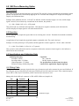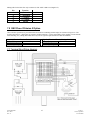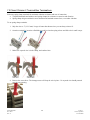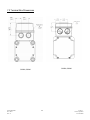
1
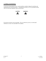
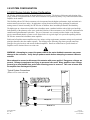
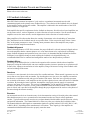
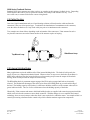
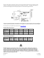
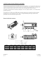
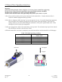
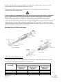
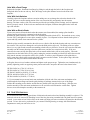
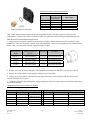
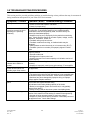
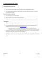
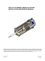
GSX and GS SERIES LINEAR ACTUATOR
INSTALLATION AND SERVICE MANUAL
Information furnished by EXLAR Corporation is believed to be accurate and reliable. However, no responsibility is assumed by EXLAR
Corporation for its use. EXLAR reserves the right to change the design and operation of the equipment described herein and any associated
motion products that may appear in this document. Information in this document pertaining to equipment not furnished by EXLAR should be
confirmed by that equipment manufacturer. EXLAR assumes no responsibility for changes to information by other manufacturers or errors in that
information or the description of that information. Information in this document is subject to change without notice.
GS/X Manual.doc
PN: 10278
Rev. JJ
1
07/01/13
Exlar Corporation
952-500-6200
TABLE OF CONTENTS
1.0 Introduction
1.1 Warranty and Limitations of Liability. . . . . . . . . . . . . . . . . . . . . . . . . . . . . . . . 3
1.2 Safety Considerations . . . . . . . . . . . . . . . . . . . . . . . . . . . . . . . . . . . . . . 4
2.0 System Configuration . . . . . . . . . . . . . . . . . . . . . . . . . . . . . . . . . . . . . . . . . . 5
2.1 Typical System Configuration
. . . . . . . . . . . . . . . . . . . . . . . . . . . . . . . . .
5
2.2 Standard Actuator Pin-outs and Connections . . . . . . . . . . . . . . . . . . . . . . . . . . 6
2.3 Feedback Information . . . . . . . . . . . . . . . . . . . . . . . . . . . . . . . . . . . . .
6
2.4 Cable Routing . . . . . . . . . . . . . . . . . . . . . . . . . . . . . . . . . . . . . . . . . .
7
2.5 Internal Holding Brake . . . . . . . . . . . . . . . . . . . . . . . . . . . . . . . . . . . . . .
7
2.6 External Limit Switches . . . . . . . . . . . . . . . . . . . . . . . . . . . . . . . . . . . . . . 9
2.7 Brake Extensions . . . . . . . . . . . . . . . . . . . . . . . . . . . . . . . . . . . . . . . . . 10
2.8 Anti-Rotation Option . . . . . . . . . . . . . . . . . . . . . . . . . . . . . . . . . . . . . . . . 11
2.9 Ingress Protection . . . . . . . . . . . . . . . . . . . . . . . . . . . . . . . . . . . . . . . .
12
3.0 Installation and Operation . . . . . . . . . . . . . . . . . . . . . . . . . . . . . . . . . . . . . . . . 13
3.1 Lubrication Requirements . . . . . . . . . . . . . . . . . . . . . . . . . . . . . . . . . . . .
13
3.2 Grease Lubrication . . . . . . . . . . . . . . . . . . . . . . . . . . . . . . . . . . . . . . . . 14
3.3 Oil Lubrication . . . . . . . . . . . . . . . . . . . . . . . . . . . . . . . . . . . . . . . . . . 14
3.4 Mounting Configurations . . . . . . . . . . . . . . . . . . . . . . . . . . . . . . . . . . . . . 15
3.5 Mounting Considerations . . . . . . . . . . . . . . . . . . . . . . . . . . . . . . . . . . . . . .16
3.6 General Operation . . . . . . . . . . . . . . . . . . . . . . . . . . . . . . . . . . . . . . . . 16
3.7 Manual Drive Operating Instructions . . . . . . . . . . . . . . . . . . . . . . . . . . . . . . . 18
4.0 Maintenance Procedures . . . . . . . . . . . . . . . . . . . . . . . . . . . . . . . . . . . . . . . . . 19
4.1 Disassembly . . . . . . . . . . . . . . . . . . . . . . . . . . . . . . . . . . . . . . . . . . . 19
4.2 Lubrication Maintenance . . . . . . . . . . . . . . . . . . . . . . . . . . . . . . . . . . . . . 20
4.3 Reassembly . . . . . . . . . . . . . . . . . . . . . . . . . . . . . . . . . . . . . . . . . . . 21
4.4 Seal Maintenance . . . . . . . . . . . . . . . . . . . . . . . . . . . . . . . . . . . . . . . . 22
5.0 Troubleshooting Procedures . . . . . . . . . . . . . . . . . . . . . . . . . . . . . . . . . . . . . . 24
5.1 Returning a Product for Repair . . . . . . . . . . . . . . . . . . . . . . . . . . . . . . . . . 25
6.0 GSX Force Measuring Option . . . . . . . . . . . . . . . . . . . . . . . . . . . . . . . . . . . . . . 26
6.1 Overview . . . . . . . . . . . . . . . . . . . . . . . . . . . . . . . . . . . . . . . . . . . .
26
6.2 Specifications and Calibration Data . . . . . . . . . . . . . . . . . . . . . . . . . . . . . . . 26
6.3 Operation
. . . . . . . . . . . . . . . . . . . . . . . . . . . . . . . . . . . . . . . . . . . 26
6.4 Wiring Code . . . . . . . . . . . . . . . . . . . . . . . . . . . . . . . . . . . . . . . . . . . 26
7.0 Class I Division 2 Option . . . . . . . . . . . . . . . . . . . . . . . . . . . . . . . . . . . . . . . . 27
7.1 Terminal Box Wiring Diagram . . . . . . . . . . . . . . . . . . . . . . . . . . . . . . . . . . 27
7.2 Class I Div 2 Terminal Box Terminations
. . . . . . . . . . . . . . . . . . . . . . . . . . . . 28
7.3 Terminal Box Dimensions . . . . . . . . . . . . . . . . . . . . . . . . . . . . . . . . . . . .
8.0 Certifications . . . . . . . . . . . . . . . . . . . . . . . . . . . . . . . . . . . . . . . . . . . . . .
29
30
Please visit www.exlar.com for information pertaining to connectors and cables.
GS/X Manual.doc
PN: 10278
Rev. JJ
2
07/01/13
Exlar Corporation
952-500-6200
1.0 INTRODUCTION
1.1 Warranty and Limitation of Liability
Products are warranted for two years from date of manufacture as determined by the serial number on the product
label. Labels are generated and applied to the product at the time of shipment. The first and second digits are the year and
the third and fourth digits represent the manufacturing week. Product repairs are warranted for 90 days from the date of
the repair. The date of repair is recorded within Exlar Corporation’s database tracked by individual product serial number.
Exlar warrants its product(s) to the original purchaser and in the case of original equipment manufacturers, to their
original customer to be free from defects in material and workmanship and to be made only in accordance with Exlar's
standard published catalog specifications for the product(s) as published at the time of purchase. Warranty or
performance to any other specifications is not covered by this warranty unless otherwise agreed to in writing by Exlar and
documented as part of any and all contracts, including but not limited to purchase orders, sales orders, order
confirmations, purchase contracts and purchase agreements. In no event shall Exlar be liable or have any responsibility
under such warranty if the product(s) has been improperly stored, installed, used or maintained, or if Buyer has permitted
any unauthorized modifications, adjustments and/or repairs to such product(s). Seller's obligation hereunder is limited
solely to repairing or replacing (at its opinion), at the factory any product(s), or parts thereof, which prove to Seller's
satisfaction to be defective as a result of defective materials, or workmanship and within the period of time, in accordance
with the Seller's stated product warranty (see Terms and Conditions above), provided, however, that written notice of
claimed defects shall have been given to Exlar within thirty (30) days from the date of any such defect is first discovered.
The product(s) claimed to be defective must be returned to Exlar, transportation prepaid by Buyer, with written
specification of the claimed defect. Evidence acceptable to Exlar must be furnished that the claimed defects were not
caused by misuse, abuse, or neglect by anyone other than Exlar.
Components such as seals, wipers, bearings, brakes, bushings, gears, splines, and roller screw parts are considered
wear parts and must be inspected and serviced on a regular basis. Any damage caused by failure to properly lubricate
Exlar products and/or to replace wear parts at appropriate times, is not covered by this warranty. Any damage due to
excessive loading is not covered by this warranty.
The use of products or components under load such that they reach the end of their expected life is a normal
characteristic of the application of mechanical products. Reaching the end of a product’s expected life does not indicate
any defect in material or workmanship and is not covered by this warranty.
Costs for shipment of units returned to the factory for warranty repairs are the responsibility of the owner of the
product. Exlar will return ship all warranty repairs or replacements via UPS Ground at no cost to the customer.
For international customers, Exlar will return ship warranty repairs or replacements via UPS Expedited Service and
cover the associated shipping costs. Any VAT or local country taxes are the responsibility of the owner of the product.
The foregoing warranty is in lieu of all other warranties (except as Title), whether expressed or implied, including
without limitation, any warranty of merchantability, or of fitness for any particular purpose, other than as expressly set
forth and to the extent specified herein, and is in lieu of all other obligations or liabilities on the part of Exlar.
Seller's maximum liability with respect to these terms and conditions and any resulting sale, arising from any cause
whatsoever, including without limitation, breach of contract or negligence, shall not exceed the price specified herein of
the product(s) giving rise to the claim, and in no event shall Exlar be liable under this warranty otherwise for special,
incidental or consequential damages, whether similar or dissimilar, of any nature arising or resulting from the purchase,
installation, removal, repair, operation, use or breakdown of the product(s) or any other cause whatsoever, including
negligence.
The foregoing warranty shall also apply to products or parts which have been repaired or replaced pursuant to such
warranty, and within the period of time, in accordance with Seller's stated warranty.
NO PERSON INCLUDING ANY AGENT OR REPRESENTATIVE OF EXLAR, IS AUTHORIZED TO
MAKE ANY REPRESENTATION OR WARRANTY ON BEHALF OF EXLAR CONCERNING ANY
PRODUCTS MANUFACTURED BY EXLAR, EXCEPT TO REFER PURCHASERS TO THIS WARRANTY.
GS/X Manual.doc
PN: 10278
Rev. JJ
3
07/01/13
Exlar Corporation
952-500-6200
1.2 Safety Considerations
As with any electro-mechanical device, safety should be considered during the installation and
operation of your GS/X Series actuator. Throughout this manual you will see paragraphs marked
with CAUTION and WARNING signs as shown below.
CAUTION
WARNING
Pay particular attention to these paragraphs. They are intended to provide you with helpful
information to ensure safe and trouble-free installation.
GS/X Manual.doc
PN: 10278
Rev. JJ
4
07/01/13
Exlar Corporation
952-500-6200
2.0 SYSTEM CONFIGURATION
2.1 GS/X Series Actuator System Configuration
GS/X Series actuators incorporate an integral brushless servo motor. The design of this motor and selection of the
proper feedback configuration allows GS/X Series actuators to be powered by nearly every brand of brushless motor
amplifier on the market.
This flexibility allows GS/X Series actuators to be incorporated into the highest performance single and multi-axis
motion control systems in use today. In applications varying from food and beverage packaging to multi-axis
turning centers to aircraft assembly, the GS/X Series of actuators show incredible performance and durability.
The high torque to volume ratio available from a brushless motor, combined with the robust, high speed and high
load capability of the planetary roller screw, make the Exlar line of linear actuators a true, all electric replacement for
cumbersome high maintenance hydraulics. The use of electronic servo control provides simpler set up and more
precise control than hydraulic systems as well. Shown below is a typical single axis system incorporating an Exlar
GS/X Series actuator and a brushless motor amplifier.
Each brand of brushless motor amplifiers may have unique wiring requirements, parameter settings and operational
principles that affect how the actuator operates. The drawing on the following page shows general connection
principles for typical resolver and encoder feedback amplifiers. Details on connections to specific brands of
amplifiers can be obtained from www.exlar.com.
WARNING: Attempting to connect the power cable to the motor feedback connector may cause
damage to the connector. Verify that pin patterns match before attempting to connect cables to
actuator.
Never attempt to connect or disconnect the actuator with power applied. Dangerous voltages are
present. Damage to equipment and injury to personnel can result. Many amplifiers have voltage
present for a considerable time period after incoming power is removed. Take care to insure that
the amplifier has discharged all power.
Typical System Connections
(Please refer to www.exlar.com
GS/X Manual.doc
PN: 10278
Rev. JJ
5
07/01/13
Exlar Corporation
952-500-6200
2.2 Standard Actuator Pin-outs and Connections
Please refer to www.exlar.com.
2.3 Feedback Information
Most GS/X Series actuators incorporate a 2 pole resolver or quadrature incremental encoder with
commutation signals as the primary rotary feedback device. The selection of this feedback device is dictated
by the amplifier used to operate the actuator. This amplifier is indicated in the model number of the GS/X
Series actuator as a 3 digit code.
Each amplifier has specific requirements for the feedback on the motor. Not all resolver-based amplifiers can
use the same resolver, resolver alignment, or relative direction of resolver rotation. Not all encoder-based
amplifiers can use the same encoder, encoder alignment or relative direction of encoder rotation.
Many amplifiers offer software that allows the entering of parameters or the downloading of "motor data
files" that dictate how the feedback must be set up on the motor. Exlar can provide many of these "motor
files" or the proper parameters to enter. Entering motor parameter data to some amplifiers may require
assistance from the amplifier manufacturer.
Feedback Alignment
When Exlar manufactures a GS/X Series actuator, the proper feedback is selected, mounted, aligned and test
run on the amplifier that the customer plans to use, or one that is known to be equivalent for confirming
proper feedback alignment and operation. In any case where it is determined that the feedback has become
misaligned, or an amplifier change is made requiring the feedback to be aligned differently, it is
recommended that Exlar be contacted and arrangements made to have that procedure performed.
Feedback Wiring
The wiring of the feedback device is critical to the operation of the actuator with the selected amplifier.
Improperly wiring the feedback cable can cause unstable operation, incorrect operation or no operation at all.
In some cases, improper current limits set in the amplifier, along with incorrect wiring of the feedback cable
can lead to damage of the motor.
Resolvers
A resolver is a non-electronic device that works like a small transformer. When rotated, it generates two sine
waves that are out of phase with one another. By decoding these two sine waves, the amplifier can monitor
the direction, revolutions traveled, and speed of rotation of the motor. Each sine wave typically represents
one revolution of the motor, so the amplifier can also use these signals to know where the motor is within that
revolution. By knowing the motor's position, the amplifier can properly time the supply of current and
voltage to the motor for it to rotate. This process is commutation. For the amplifier to properly commutate
the motor, it must have a reference, or zero, point from which to track the motor's rotation. This reference
point is critical, and is provided to the amplifier through the proper alignment of the resolver to the phases of
the motor during the actuator assembly.
Encoders
An incremental encoder is an electronic rotary device that transmits a string of electrical pulses when rotated.
Most brushless motors or servo systems that use incremental encoders use what is called a quadrature
encoder. Typical brushless motor encoders use two data channels labeled A&B to provide direction, velocity
and position information. The Channel labeled I or Z has one pulse per revolution and is called the index.
The channels labeled as hall signals or commutation signals are typically labeled S1, S2 & S3; Hall 1, 2 & 3;
or Hall A, B & C, depending on the manufacturer's conventions. These signals give the amplifier the
commutation information that it needs to properly rotate the motor.
GS/X Manual.doc
PN: 10278
Rev. JJ
6
07/01/13
Exlar Corporation
952-500-6200
GS/X Series Feedback Devices
Standard GS/X Series actuators use either resolvers or encoders as their primary feedback device. Depending
on the amplifier that will be used to operate the actuator, the hookup of the actuator can vary. Go to
www.exlar.com, or contact Exlar for the correct wiring details.
2.4 Cable Routing
Over time, liquid contaminants such as oil and cleaning solutions will run down the cables and into the
connectors if they are of an exposed type. To minimize the introduction of contaminants to the connector,
route the cables so that there is a loop in the cable just prior to its attachment to the connector.
Two examples are shown below depending on the orientation of the connectors. Units mounted in such a
way that the connectors are on the bottom surface of the actuator require no looping.
Side Mount Loop
Top Mount Loop
2.5 Internal Holding Brake
Many applications require the addition of the Exlar internal holding brake. The brake is held open by the
supply of power to a magnetic/mechanical clutch. Whenever there is not power to the brake, the armature is
held in place which prevents the inverted roller screw from turning and prevents the output rod from back
driving, which in turn prevents the output rod from moving.
The RB holding brake is permanent magnet engaged, the EB is spring engaged and both are electrically
released. The mechanical advantage of the roller screw allows the holding brake to prevent back driving of
the load. The holding capacity of the brakes is sufficient to hold the rated force of the actuator when used in
grease lubricated units. The use of oil as a lubricant reduces the holding capacity of the brake.
Historically, Exlar actuators and motors which had holding brakes are supplied with a transient suppression diode
which can be wired to the actuator or motor brake connector. With the changes in servo amplifier and control
technology, there are now instances where the diode is not required to be within the motor. An example of this is a
control system using a dedicated brake control relay which contains transient suppression components.
GS/X Manual.doc
PN: 10278
Rev. JJ
7
07/01/13
Exlar Corporation
952-500-6200
Because of this change in technology, Exlar now provides the transient suppression diode separately from the
actuator, for inclusion in the brake control circuitry as needed by the end user. A schematic, shown below, is
provided with the shipped product showing the typical use of the transient suppression diode.
If the user is uncertain about their requirements for transient suppression, they should refer to their servo amplifier or
controller technical documentation, or contact their servo amplifier or controller manufacturer for technical support.
For connection of your amplifier and actuator refer to www.exlar.com.
RB (Rear Brake) Specifications
BRAKE
SPECIFICATIONS
Holding torque
(w/o oil)
Current @ 24 VDC
Coil resistance
(polarity sensitive)
GSX20
GSX30
GSX40
GSX50
GSX60
19 lbf-in
(2.2 Nm)
0.75 Amps
70 lbf-in
(8 Nm)
0.75 Amps
97 lbf-in
(11 Nm)
0.88 Amps
354 lbf-in
(40 Nm)
1.0 Amps
708 lbf-in
(80 Nm)
1.3 Amps
113 Ohms
33 Ohms
27 Ohms
24 Ohms
21 Ohms
GS/X20
GS/X30
GSX40
GS45
GS/X60
25 lbf-in
(2.8 Nm)
0.75 Amps
40 lbf-in
(4.5 Nm)
0.75 Amps
120 lbf-in
(13.56 Nm)
0.88 Amps
80 lbf-in
(9 Nm)
0.88 Amps
708 lbf-in
(65 Nm)
1.3 Amps
EB (Front Brake) Specifications
BRAKE
SPECIFICATIONS
Holding torque
(w/o oil)
Current @ 24 VDC
DO NOT attempt to operate the actuator with the brake applied. Allowing the actuator to
operate with the brake applied may cause serious damage to the actuator and/or the brake.
Do not use the brake to support heavy loads while an operator is under the load. Provide
another means to lock the load in position. The brake is a spring applied friction mechanism
and does not provide a positive lock.
GS/X Manual.doc
PN: 10278
Rev. JJ
8
07/01/13
Exlar Corporation
952-500-6200
2.6 GS/X Linear Actuator External Limit Switch
With the anti-rotate option (Section 2.8) the GSX actuator can accommodate 1, 2 or 3 external limit switches for use
as end of travel limit switches or home position sensors in a low profile extruded channel housing. A bracket with
inductive proximity switches mounts to the tie rods and senses a traveling magnet inside the extrusion.
The number of switches desired is selected by ordering the L1, L2 or L3 option, in which 1, 2 or 3 switches will be
provided, respectively.
The switches are 9-30 VDC powered, PNP output, with either normally open or normally closed logic operation
depending on the switch configuration ordered. Below is a diagram indicating which logic operation will be
provided for each switch, based on the option ordered.
External Limit Switch Locations
DIM "A"
GSX20
GSX30
GSX40
GSX50
GSX60
GS/X Manual.doc
PN: 10278
Rev. JJ
3" Stroke
5.515
6.932
n/a
n/a
n/a
6" Stroke
8.515
9.832
9.832
11.667
10.461
8" Stroke
n/a
n/a
11.83
n/a
n/a
10" Stroke 12" Stroke 14" Stroke 18" Stroke
12.500
14.515
n/a
n/a
13.832
15.832
17.832
21.832
13.832
15.832
n/a
21.832
15.667
n/a
19.667
n/a
14.461
n/a
n/a
n/a
9
07/01/13
Exlar Corporation
952-500-6200
CONFIGURATION OF LOGIC OF STANDARD SWITCH OPTION SELECTIONS
Option
SW1
SW2
SW3
L1
Not Supplied
Normally Open
Not Supplied
L2
Normally Closed
Not Supplied
Normally Closed
L3
Normally Closed
Normally Open
Normally Closed
Switch Type
Normally Closed Switch
Normally Open Switch
Exlar Part Number
43404
43403
Turck Part Number
BIM-UNT-RP6X
BIM-UNT-AP6X
2.7 GS/X Linear Actuator Brake Extensions
The brake option may add a third connector to the actuator and require a case extension to accommodate the
internal components. Option also slightly reduces the available stroke from the actuator. The case extension
dimension and stroke reductions are shown below.
GSX Actuator
GSX20
GSX30
GSX40
GSX50
GSX60
GS/X Manual.doc
PN: 10278
Rev. JJ
A – Brake Length Ext.
1.78 in (45.21 mm)
1.61 in (40.9 mm)
2.33 in (59.18 mm)
2.5 in (63.45 mm)
3.575 in (90.81 mm)
GS Actuator
GS20
GS30
GS45
GS50
10
A – Brake Length Ext.
1.78 in (45.21 mm)
1.77 in (44.96 mm)
2.498 in (63.45 mm)
3.544 in (90.02 mm)
07/01/13
Exlar Corporation
952-500-6200
2.8 GS/X Series Linear Actuator Anti-rotation Option
The unique design of the GS/X Series linear actuators allows the extending rod to rotate. This provides
simple setup of the actuator by allowing the user to rotate the rod and thread it in and out of the actuator for
mechanical attachment or system testing. This feature also requires that the rod be kept from rotating when
used in its dedicated application to insure proper linear motion. In most applications, such as those where
the load is coupled to linear bearings, or some other support device, the load cannot rotate, and thus provides
anti-rotation for the extending rod of the actuator.
For applications in which the load is free to rotate, Exlar offers the anti-rotation systems shown below. The
drawings next page show the rod and bushing on only one side of the actuator. For long stroke actuators, the
rod and bushing are required on both sides of the actuator.
Anti-rotate Dimensions GS/X20, 30, 40, 45 and 60 (For GSX50 see next page)
Dimensions
in (mm)
A
B
C
D
E
F
G
H
GS/X20
GS/X30
GS/X40 and 45
GS/X60
0.60 (15.2)
1.81 (46.0)
0.54 (13.7)
1.00 (25.4)
0.44 (11.2)
0.28 (7.11)
0.31 (7.87)
0.37 (9.40)
0.79 (20.1)
2.54 (64.5)
0.71 (18.0)
1.30 (33.0)
0.44 (11.2)
0.32 (8.13)
1.69 (42.9)
0.50 (12.7)
1.25 (31.8)
3.78 (96.0)
0.98 (24.9)
1.64 (41.7)
0.63 (16.0)
0.38 (9.65)
1.69 (42.9)
0.50 (12.7)
1.75 (44.5)
5.79 (147)
1.55 (39.4)
1.94 (49.3)
0.75 (19.1)
0.50 (12.7)
2.81 (71.4)
1.00 (25.4)
For GSX50 anti-rotate dimensions, see page 12.
GS/X Manual.doc
PN: 10278
Rev. JJ
11
07/01/13
Exlar Corporation
952-500-6200
Anti-rotate Dimensions (GSX50)
2.8 GS/X Series
2.9 Ingress Protection Rating
The standard IP rating for GS/X Series actuators is IP65S. Ingress protection is divided into two categories; solids
and liquids. For example, in IP65 the three digits following “IP” represent different forms of environmental
influence:
• The first digit represents protection against ingress of solid objects.
• The second digit represents protection against ingress of liquids.
• The suffix digit represents conditions of motion during the operation.
Digit 1 - Ingress of Solid Objects
The IP rating system provides for 6 levels of protection against solids.
1 Protected against solid objects over 50mm e.g. hands, large tools.
2 Protected against solid objects over 12.5mm e.g. hands, large tools.
3 Protected against solid objects over 2.5mm e.g. wire, small tools.
4 Protected against solid objects over 1.0mm e.g. wires.
5 Limited protection against dust ingress. (no harmful deposit)
6 Totally protected against dust ingress.
GS/X Manual.doc
PN: 10278
Rev. JJ
12
07/01/13
Exlar Corporation
952-500-6200
Digit 2 - Ingress of Liquids
The IP rating system provides for 9 levels of protection against liquids.
1 Protected against vertically falling drops of water or condensation.
2 Protected against falling drops of water, if the case is disposed up to 15 degrees from vertical.
3
Protected against sprays of water from any direction, even if the case is disposed up to 60
degrees from vertical.
4 Protected against splash water from any direction.
5 Protected against low pressure water jets from any direction. Limited ingress permitted.
6 Protected against high pressure water jets from any direction. Limited ingress permitted.
7 Protected against short periods of immersion in water of 1m or less for 30 minutes or less.
8 Protected against long durations of immersion in water.
9 High-pressure, high-temperature wash-down applications.
Suffix
S Device standing still during operation
M Device moving during operation
3.0 INSTALLATION AND OPERATION
3.1 Lubrication Requirements
GS/X Series actuators require either grease or oil lubrication. Actuators that operate in the lower range of
their performance capabilities may use grease. Oil lubrication is required for actuators that will be running
near the upper end of their performance limits. Recirculating oil provides lubrication and cools the actuator.
Determining if an application will require oil or grease lubrication should be done prior to ordering the
actuator.
The following chart can be used to help determine oil vs. grease lubrication requirements:
GS Series Actuators Grease / Oil Operating Regions
RMS Speed as % of
Maximum Rated Speed
100%
80%
60%
Grease
Oil
40%
20%
0%
0%
20%
40%
60%
80%
100%
RMS Applied Load as %
of Maximum Rated Load
GS/X Manual.doc
PN: 10278
Rev. JJ
13
07/01/13
Exlar Corporation
952-500-6200
3.2 Grease Lubrication
If your application uses grease lubrication, the actuator is shipped from the factory fully greased and ready
for installation. Exlar recommends using Mobilith SHC 220, a high performance, extreme-pressure grease.
The unique physical properties of the synthetic base oil provide outstanding protection against wear, rust,
corrosion and high or low-temperature degradation. Mobilith SHC allows for very low starting and running
torque values. Its operating range is -40 degrees C to 177 degrees C (-40 degrees F to 350 degrees F).
3.3 Oil Lubrication for High Power / Low Maintenance Operation
Consult Exlar to discuss your application if you plan to use oil cooling with your GSX actuator.
Exlar GSX actuators are delivered as standard with high performance lithium grease. This provides for capability to
provide thousands of hours of service between re-lubrication periods in most applications.
Some applications into which GSX actuators are deployed involve high speed and high cycle rate with high
acceleration, high force or a combination. To provide cooling of the motor within the GSX actuator for operation at
the elevated current levels needed to perform these applications, GSX actuators can be configured to be used with
recirculated oil lubrication. Using oil lubrication requires only low flow rates and low pressures to provide
significant additional cooling.
There are several application and actuator configuration details that are involved in using a GSX with oil cooling,
and any application that will use oil cooling must be discussed with Exlar Application engineering so that the correct
actuator options can be selected, and the details of the application reviewed.
In linear actuator applications where high speed motion exists it is possible that the internal movement of the roller
screw follower will act as a pump and create oil pressure higher than allowed. Take care that the oil pressure is
monitored during cycling. If it appears that the pumping action of the actuator is causing spikes in the oil pressure it
is recommended that the customer work directly with Exlar Engineering to determine if actuator configuration
changes or application changes are required.
In all cases the reservoir in the lubrication system must be located below the level of the actuator to prevent the
“filling up” of the actuator.
There is a high likelihood that over time as a result of seal wear and hardening, both external and internal leaks will
develop. This will allow the movement of small amounts of oil to undesirable locations, specifically the encoder
compartment and/or output rod. Exlar uses the finest quality linear rod seals available, rated for pressures beyond
what should normally exist inside the actuator, however, over time you may find small amounts of oil on the output
rod (linear) or shaft (rotary) which escaped through the output rod or shaft seal. In some cases this may accumulate
to form an occasional drip.
This becomes more critical when oil passes the feedback section seal and begins to accumulate in the feedback
compartment of the actuator. Over time this oil may migrate to the encoder (if an encoder is used) potentially causing
a failure of the feedback device. To avoid this intrusion situation and a possible untimely actuator failure, it is highly
recommended that a drain port be provided in the feedback section of the actuator any time oil flow
lubrication/cooling is employed. Since the oiling system reservoir is located below the actuator, the drive can be
hooked directly to the reservoir with a plastic housing. It is recommended to work with Exlar Application
Engineering to determine the best actuator configuration for your application.
GS/X Manual.doc
PN: 10278
Rev. JJ
14
07/01/13
Exlar Corporation
952-500-6200
A schematic of a possible example oil system is shown below. Exlar Application Engineering can assist you in the
development of your own oil system, or suggest pre-packaged oil circulation systems.
The maximum allowable internal oil pressure for the GS/X Series actuators is 10 psi. Take
care to insure that this pressure limit is maintained. Failure to do so may cause damage to
the internal sealing components.
Example Oil System Schematic
NOTE: Values and
configuration are for
example purposes only.
As shown in the schematic to
the left, a check valve or other
method of pressure regulation
should be used to maintain an
internal actuator oil pressure of
5 psi.
Filtering of 25 microns or better
should be used. Simple
radiators or heat exchangers can
be used to maintain oil
temperature.
Exlar can recommend the appropriate oils for your specific application.
3.4 Mounting Configurations
The GS/X Series actuators come with a variety of mounting configurations. The standard configurations
available are Side Mount, Extended Tie Rods, Rear Clevis and Front Flange. Side Mounted Trunnions are
also available for some units. Certified drawings are available from Exlar. General drawings are shown in
the Exlar catalog.
GS/X Manual.doc
PN: 10278
Rev. JJ
15
07/01/13
Exlar Corporation
952-500-6200
3.5 Mounting Considerations
Every effort should be made to minimize misalignment as much as is possible. Misalignment of the GS/X
Series actuator with respect to whatever load the actuator is being used to move is of great concern. Any
misalignment will decrease the life of the components within the actuator and also may create problems
within the application associated with misalignment.
Excessive side load on the output rod of the actuator will dramatically reduce the life of the
actuator and should be avoided completely. Side load can be caused from misalignment or
loading that is not inline with the actuator output rod.
A GS/X Series actuator with the Side Mount option comes with threaded holes in the faceplate and endplate.
Exlar recommends using hardened fasteners to mount a GS/X Series actuator to your machine frame. Exlar
also recommends threading the mounting fastener into as much of the threaded hole in the actuator as
possible, to prevent stripping out the threads in the actuator’s mounting holes.
Note: Side Mount actuators may have reduced maximum load rating.
A GS/X Series actuator with the Extended Tie Rod mounting option comes with hex nuts on the faceplate
that are tightened down enough to keep the actuator together during shipping. When mounting the actuator
to your machine, these nuts should be removed and the tie rods should be placed through the machine frame
and the nuts used on the back side of the machine’s mounting flange. The tie rod nuts should then be
tightened with a torque wrench to the following values:
GS/X20: 20 lbf-in (1.7 lbf-ft, 2.26 N-m)
GS/X30: 90 lbf-in (7.5 lbf-ft, 10.16 N-m)
GS/X40 and 45: 240 lbf-in (20 lbf-ft, 27.12 N-m)
GSX50: 600 lbf-in (50 lbf-ft, 67.79 N-m)
GS/X60: 600 lbf-in (50 lbf-ft, 67.79 N-m)
Failure to properly tighten the tie rods can cause damage to the actuator and possible
premature failure. Over-tightening of the tie rods can cause damage to the actuator and
affect normal operation.
3.6 General Operation
The GS/X Series linear actuators function in the same manner as a brushless servomotor. The servo
amplifier is used to rotate the motor at controlled speed and torque, and for controlled numbers of
revolutions and move times. This rotary motion is translated into linear motion by the internal planetary
roller screw mechanism of the GS/X Series linear actuator.
See sections 2.6, 2.7 and 2.8 regarding the holding brake, external limit switches and anti-rotate
mechanisms, that can affect the operation and motion of the actuator.
GS/X Manual.doc
PN: 10278
Rev. JJ
16
07/01/13
Exlar Corporation
952-500-6200
The relationship between the rotary motion of the motor and the linear motion of the actuator corresponds to
the following relationships:
Linear Distance Traveled (in) = (Motor Revolutions)*(Roller Screw Lead)
Linear Speed (in/sec) = ((Motor RPM) / 60)*(Roller Screw Lead)
Linear Force (lbf) = ((Motor Torque (in-lbf))*(2π)*(efficiency)) / (Roller Screw Lead (in))
All of the above relationships require proper anti-rotation of the GS/X Series actuator rod.
For more information on sizing and selection of GS/X Series actuators and servo amplifiers to power them,
consult the sizing and selection section of the Exlar catalog.
Motor RMS current must be maintained at a level below the continuous current rating of the
GS/X Series actuator or damage to the motor stator will result.
The peak current setting must be maintained at a level below the peak current rating of the
GS/X Series actuator or damage to the stator will result.
Care should be taken not to exceed the physical travel limits of GS/X Series Actuators.
Doing so will cause the actuator to end-crash internally. End crashes can physically
damage the roller screw and the internal components of the actuator. Care should be taken
to avoid high speed impact with objects of high rigidity that immediately stop the travel of
the actuator with no deceleration or energy absorption. An example would be a high speed
impact of two solid steel parts. The resulting impact will create a very short effective
deceleration time. Kinetic energy contained in the rotating inertia of the actuator and motor
can possibly generate extremely high impact forces that exceed the mechanical capacities
of the actuator and cause physical damage to the actuator. For applications requiring this
type of impact, contact Exlar application engineering to insure that the actuator is properly
sized or provisions made to absorb the induced energy.
GS/X Manual.doc
PN: 10278
Rev. JJ
17
07/01/13
Exlar Corporation
952-500-6200
3.7 Manual Drive Operating Instructions
Important:
If manually driving through a brake or high force is necessary, please consult Exlar engineering.
If a power tool is used to operate the manual drive the speed should be limited to 600 RPM
An impact driver should never be used to operate the manual drive.
Extreme caution should be taken when approaching end of stroke of the actuator or system.
1) Press down on the hex until you feel you have bottomed out the manual drive. Constant downward force is
required to maintain engagement during operation.
2) Give the hex a slight turn while observing if you are moving the rod or not. It is possible that during engagement
the gear teeth have not completely engaged; this will prevent the gears from meshing. If the rod is not
moving continue to press down while turning the manual drive slowly until it pushes farther down. When
this happens you have proper gear engagement.
3) After gear engagement is achieved, the manual drive can be operated. The maximum torque input for the manual
drive should not exceed the values shown in Table 1.
4) When the manual drive movement is completed, cease the downward force and the manual drive will disengage.
Table 1. Maximum operating conditions
Model
Maximum Torque
in-lbs / (Nm)
GSX 20
10 / (1.1)
GSX 30
30 / (3.4)
GSX 40
40 / (4.5)
GSX 50
80 / (9.0)
GSX60
105 / (11.8)
Push down
Disengaged
Engaged
Detailed Section View
GS/X Manual.doc
PN: 10278
Rev. JJ
18
07/01/13
Exlar Corporation
952-500-6200
4.0 MAINTENANCE PROCEDURES
4.1 Disassembly
If your actuator has a preloaded roller screw, do not remove it from the cylinder. Preloaded
screws require special tooling and procedures for proper disassembly and reassembly.
Contact Exlar Corporation to arrange for maintenance of a preloaded screw actuator.
Refer to the exploded view on the following page.
1.) Remove the actuator assembly from the machine by disconnecting the cables, main rod coupling and
actuator mounting bolts or fasteners.
2.) If your unit does not have an external anti rotate assembly, skip this step. Loosen the two machine
screws that clamp the anti-rotate cross member to the actuator output rod. Slide the anti-rotate mechanism
forward and off the actuator.
3.) Remove the rear tie rod nuts from the back of the actuator.
Extreme care should be taken when removing the tie rod nuts or tie rods so as not to twist
or pull on the end cap of the actuator. The end cap houses the feedback device.
Alignment of this feedback device to the phases of the motor is critical to the operation of
the system. Some feedback devices are sensitive to movement of their mounting surface
once installed and can be damaged if care is not taken.
4.) If your actuator does not have a front flange, skip this step. Slide the front flange forward and off the
actuator. The tie rods will remain attached to the front flange.
5.) If your actuator has an internal brake or internal limit switches, read the following three
paragraphs before proceeding. Remove the faceplate from the actuator by gently pulling it forward. It is
sealed by an O-ring, and does require some force to remove. Take care not to damage the front seal on the
threads of the actuator output rod when removing the faceplate.
Limit Switches
If your unit has internal limit switches, you will see that there is an extension of the actuator case that houses
the limit switches and has the limit switch connector mounted to it. This case extension has a cylindrical
assembly inside it with mounting surfaces for the limit switches. Carefully pull this entire assembly (case
extension and face plate) forward to remove it from the actuator. The mounting assembly for the switches is
not fastened to the case extension, so remove it slowly and ensure that all of the parts are moving together so
that damage is not done to the switches or their wires.
Electric Brake
For units that have the EB option, there is also a case extension similar to the limit switch option. The brake
housing is fastened to the back of the faceplate. The faceplate, case extension and brake housing can be
removed together by gently pulling the case extension and faceplate forward. With the brake assembly
GS/X Manual.doc
PN: 10278
Rev. JJ
19
07/01/13
Exlar Corporation
952-500-6200
removed, you will see the brake spline attached to the roller screw cylinder. Remove the screws for the
spline assembly and remove it from the roller screw cylinder.
The RB option requires removal of the feedback device to access and Exlar should be consulted for
assistance, or the unit returned to Exlar.
If your actuator has a preloaded roller screw, do not remove it from the cylinder. Preloaded
screws require special tooling and procedures for proper disassembly and reassembly.
Contact Exlar Corporation to arrange for maintenance of a preloaded screw actuator.
6.) When the face plate and limit switch or brake assembly (including spline) is removed, the thrust bearing
and the open end of the roller screw internally threaded cylinder (ITC) are visible. The roller screw can be
removed by turning it counter clockwise and threading it out of the cylinder. It may be necessary to hold the
roller screw cylinder from turning to remove the screw.
Exploded View of GS Series Actuator
4.2 Lubrication Maintenance
Grease lubricated units will require periodic inspection and renewal of the bearing and roller screw grease.
The table below shows the recommended grease renewal period.
RMS Rotational
speed(RPM)
250
500
1000
1500+
GS/X Manual.doc
PN: 10278
Rev. JJ
Recommended Grease Renewal Period hours)
CASE TEMP 65
degrees C (149
degrees F)
10,000
8,500
6,000
3,500
CASE TEMP 80
degrees C (176
degrees F)
5,000
4,250
3,000
1,750
20
CASE TEMP 95
degrees C (203
degrees F)
2,500
2,125
1,500
875
07/01/13
Exlar Corporation
952-500-6200
Grease Renewal
The angular contact thrust bearings located in the front of the actuator, the roller screw cylinder, and the
roller screw assembly are the components that require grease. They require a coating of grease. They do not
need to be packed with grease. Excess grease only requires more torque from the motor when returned to
operation, and does not improve the lubrication of the unit.
1.) Use a brush to work approximately 0.5 in3 of grease for every 3 inches of stroke length into the roller
screw cylinder. Be sure to cover all of the threaded areas of the cylinder.
2.) Use a brush to work grease in to the roller screw assembly. Be sure to cover all the threaded surfaces of
the screw assembly. This can be accomplished by applying grease to a few places on the roller screw
assembly and rotating the components repeatedly in both directions to work the grease into the assembly.
3.) Force grease into the front of the thrust bearing assembly. Make a concerted effort to insure that the
grease is well worked in. Grease must reach the bearing just behind the bearing that is visible as well. Use
the following amounts of grease for each size roller screw and bearing:
GS/X20: 0.5 in3 GS/X30: 0.75 in3
GS/X40/45: 1.0 in3
GSX50: 1.5 in3 GS/X60: 2.0 in3
Oil Lubrication
It is recommended to regularly check the oil during operation to insure that it is flowing properly and
maintaining case temperature. It is also recommended to check the lubrication regularly to insure that the
lubricant being supplied to the actuator is clean. A filtering system is required, 25 microns or better filtering
is recommended.
4.3 Reassembly
1.) Rethread the roller screw into the internally threaded cylinder (ITC). It is a multiple start screw, and this
is not always easy. DO NOT FORCE THE ROLLER SCREW INTO THE CYLINDER. It is best to have
the actuator vertical with the open end of the roller screw cylinder facing up. Position the roller screw above
the cylinder so that it is aligned axially with the ITC. Slowly turn the roller screw 1/4 to 1/2 turn
counterclockwise while in contact with the ITC. This will help to align the threads on the roller screw with
the threads in the ITC. Rotate the roller screw clockwise and it should begin to thread into the cylinder. If it
does not turn freely, remove it and begin again. When threading the screw into the cylinder, it will roll
freely into the actuator. When it reaches the portion of the cylinder that contains the motor magnets, the
roller screw will be more difficult to turn because of the magnetic field of the magnets. THIS IS NORMAL.
Continue to thread the roller screw into the cylinder. When it reaches the bottom, it will become difficult to
turn and the motor and bearings will begin to rotate with it. The roller screw is now fully inserted into the
cylinder.
2.) Place a small amount of seal lubricant on the inside surface of the seal/bushing assembly.
3.) Replace faceplate and case extension:
Units Without Electric Brake or Limit Switch Options
Carefully slide the faceplate and bushing/seal assembly over the actuator rod end, while guiding the tie rods
through the holes in the rear end cap of the actuator. The seal is a tight fit on the rod end. Take care not to
damage the seal on the threads of the extending rod. Standard GS/X Series rods have a chamfer to provide a
lead in for replacement of the seal and bushing. Be sure that the faceplate seats completely and squarely on
the front of the actuator. The inner surface of the faceplate provides the pre-loading for the bearings, and it
is important that it is properly seated.
GS/X Manual.doc
PN: 10278
Rev. JJ
21
07/01/13
Exlar Corporation
952-500-6200
Units With a Front Flange
Replace the faceplate. Remount front flange by sliding tie rods through the holes in the faceplate and
through the holes in the rear end cap. Place the flange on the pilot diameter located on the front of the
faceplate.
Units With Limit Switches
Carefully replace the faceplate and case extension taking care not to damage the seal on the threads of the
rod end. Be sure to seat the mating portion of the case extension fully and squarely into the actuator
housing. The inner surface of the case extension provides the pre-loading for the bearings, and it is important
that it is properly seated. If the tie rods are attached to the faceplate, slide them through the holes in the end
cap of the actuator.
Units With an Electric Brake
If power was removed form the brake when the actuator was disassembled, the mating spline should be
centered and in position to be remounted to the brake spline.
Remount the spline assembly to the roller screw internally threaded cylinder (ITC). Re-install the screws using
Loc-tite 22231, and tighten to secure spline assembly in place. It is important to insure that the brake spline is
square and fully seated when remounted to the cylinder.
With the spline assembly remounted to the roller screw cylinder, slide the brake housing and case extension onto
the actuator. Take care not to damage the seal on the threaded portion of the rod. The mating of the two spline
halves is a very tight fit and can make reassembling a brake unit very difficult. Press the case extension and brake
assembly onto the actuator housing so that the splines mate, and the case extension seats fully. If the case
extension does not seat fully the spline halves are not mated and the brake will not work properly. When the
contact between the brake halves is felt, gently rotating the actuator extending rod clockwise until it has traveled
fully into the actuator can rotate the roller screw cylinder. To achieve proper alignment of the spline halves,
slowly rotate the cylinder while pressing the brake extension onto the actuator. As the splines align, the brake
extension will fully seat onto the main actuator housing.
4.) Replace the rear tie rod washers and nuts and tighten to the proper torque. Tighten the nuts simultaneously by
partially tightening each in an opposing corner pattern until each is torqued to the rated value shown below.
GS/X20: 20 lbf-in (1.7 lbf-ft, 2.26 N-m)
GS/X30: 90 lbf-in (7.5 lbf-ft, 10.16 N-m)
GS/X40/45: 240 lbf-in (20 lbf-ft, 27.12 N-m)
GSX50: 600 lbf-in (50 lbf-ft, 67.79 N-m)
GS/X60: 600 lbf-in (50 lbf-ft, 67.79 N-m)
5.) If your actuator has an external anti-rotate mechanism, slide the rod of the anti-rotate mechanism rod or
rods through the front flange and into the guide bushing or bushings mounted to the rear of the flange.
Position the extending rod so that the wrench flats are parallel to the long side of the flange. Slide the cross
member assembly of the anti-rotate mechanism over the end of the rod and onto the wrench flats. Tighten
the two screws that clamp the assembly to the actuator rod.
4.4 Seal Maintenance
It is recommended that at the suggested time of lubrication the main rod seal and bushing assembly be replaced. The
main rod seal can be removed by threading it out of the face plate using a standard rod seal gland wrench or spanner
wrench. A new main rod seal can be slid over the main rod, taking care not to touch the seal material to the threaded
rod end. To have this service performed for you, contact Exlar Engineering or arrange with Exlar Returns
Department to send your unit in for service.
GS/X Manual.doc
PN: 10278
Rev. JJ
22
07/01/13
Exlar Corporation
952-500-6200
Seal Kits for Grease-Lubricated Actuators
GSX20
GSX30
GSX40/GS45
GSX50
GSX60
Standard Main
Rod Seal Gland
Part Numbers
18929
19020
19021
22706
19022
Install Torque
100 lb-in (11.29 N-m)
200 lb-in (22.58 N-m)
360 lb-in (40.67 N-m)
660 lb-in (74.57 N-m)
900 lb-in (101.69 N-m)
Main Rod Gland Seal and Bushing
Note: Some actuators are provided with special rod gland seals due to chemical exposure or other special
requirements. Contact Exlar if there is a question about your particular actuator having a standard material seal.
Main Rod Seal Gland Installation/Replacement:
1. Using proper sized gland or spanner wrench, remove existing seal from actuator face plate, and slide off the
actuator rod. This will require the removal of any rod attachments. One source for gland wrenches is Martin Fluid
Power. http://www.mfpseals.com/seal_repair_kits/parker-2.shtml
Exlar Actuator
Model
Martin Fluid Power
Part No.
Size (in)
Description
GSX20-30
PH-0695900000
1/2, 5/8
Rod Gland Wrench
GSX40
PH-0695910000
1
Rod Gland Wrench
GSX50
PH-0695920000
1-3/8
Rod Gland Wrench
GSX60
PH-0695930000
1-3/4
Rod Gland Wrench
2. Remove the o-ring from the o-ring grove located inside the opening from which the seal was just removed.
3. Replace the o-ring with the o-ring supplied with the new rod seal gland.
4. Taking care not to touch the seal material to any sharp rod features such as threads, slide the seal on to the
actuator rod and to the face plate.
5. Using the appropriate gland and spanner wrench, tighten the seal to the proper torque level indicated in the tables
provided on this page.
Optional Seal Kits for Oil-Lubricated Actuators
Kits Including Seal, Wiper, Back-up Ring, O-ring and FSB
Model
Part Number
Install Torque
GSX20
PN 43312
100 lb-in (11.29 N-m)
GSX30
PN 40381
200 lb-in (22.58 N-m)
GSX40
PN 40515
360 lb-in (40.67 N-m)
GSX50
PN 40516
660 lb-in (74.57 N-m)
GSX60
PN 43309
900 lb-in (101.69 N-m)
Kits Including Seal, Wiper, Back-up Ring, O-ring
Model
Part Number
Install Torque
100 lb-in (11.29
GSX20
PN 43527
)
200 lb-in (22.58
GSX30
PN 43528
)
360 lb-in (40.67
GSX40
PN 43529
)
660 lb-in (74.57
GSX50
PN 43530
)
900 lb-in (101.69
GSX60
PN 43531
)
GS/X Manual.doc
PN: 10278
Rev. JJ
23
07/01/13
Exlar Corporation
952-500-6200
5.0 TROUBLESHOOTING PROCEDURES
This section provides you with guidelines and hints on troubleshooting various problems that may be encountered
during installation and operation of your Exlar GS/X Series actuator.
Symptom / Trouble
Possible Cause / Troubleshooting Procedure
No response from actuator.
1. Check amplifier for faults that may indicate problem.
2. Check to insure that amplifier is enabled.
3. Check for proper wiring.
1. Amplifier may be improperly tuned. Check all gain settings.
If a motor file, or parameters specific to your amplifier/actuator
combination have been supplied by Exlar, be sure that they are
entered or downloaded properly.
2. Amplifier may be set up improperly for the particular motor being
used. Check amplifier settings for number of poles, voltage, current,
resistance, inductance, inertia, etc.
3. Feedback wiring may be incorrect.
4. Feedback conductors touching, or feedback cable may be
damaged.
5. Motor phases are wired incorrectly or in incorrect order. (R,S,T).
6. Feedback (resolver or encoder) is improperly aligned. Contact
Exlar.
1. Load is too large for the capacity of the actuator or too much
friction is present.
2. Excessive side load.
3. Misalignment of output rod to load.
4. Amplifier has too low of current capacity or is limited to too low of
current capacity.
1. Check actuator mounting. Insure that the actuator is securely
mounted.
2. Amplifier is improperly tuned (wrong gain settings.) Tune amplifier.
1. Install Exlar anti-rotation assembly or incorporate anti-rotation into
the application.
Actuator seems to be enabled
(receiving current) but is not
operating or is operating
erratically.
Actuator cannot move load.
Actuator housing moves or
vibrates when shaft is in
motion.
Output rod rotates during
motion and thus does not
provide proper linear motion.
Limit switches not functioning.
Brake does not hold load in
place.
Actuator is overheating.
GS/X Manual.doc
PN: 10278
Rev. JJ
1. Limit switches wired improperly. Refer to manual.
2. The device being driven by the limit switches is not compatible with
the electrical output of the limit switch. Check device requirements.
3. Switches have been damaged by improper wiring or improper
voltage applied. Replace switches.
1. Load is larger than the capacity of the brake.
-check load level against actuator rating
-oil lubricated units reduce holding capacity of the brake
2. Brake is not engaged. (Power is not removed, or only partially
removed from brake).
3. Brake is being used as other than a power loss holding brake.
1. Insufficient cooling for application requirements. See oil cooling
section of this manual or Exlar catalog or contact Exlar engineering.
2. Actuator is being operated outside of continuous ratings.
3. Amplifier is poorly tuned causing excessive unnecessary current to
be applied to motor. Check Gain settings.
24
07/01/13
Exlar Corporation
952-500-6200
5.1 Returning Product for Repair
STANDARD REPAIR LEADTIME:
•
Two weeks for written evaluation from Exlar
•
Two weeks from receipt of approval (by fax or email) for repair where parts are available.
•
An evaluation charge per unit after evaluation applies if customer chooses not to repair; or if product is
found not in need of repair.
EXPEDITED REPAIR LEADTIME:
•
An expedite charge per unit can be quoted.
•
This provides one week for written evaluation from Exlar
•
This provides one week from receipt of approval (by fax or email) for repair where parts are available.
PROCEDURE:
•
Please discuss the return with Exlar Technical Support prior to requesting an RGA number to see if it is
possible to resolve the issue prior to return.
•
If it is determined that an RGA number is required, please do so by contacting the Returned Goods
Administrator. Phone 952-500-6200 or email [email protected].
o
International Repairs: Closely follow instructions provided by the Exlar Returned Goods
Administrator. Failure to comply with issued instructions may result in delays for repair and return.
•
Exlar requires a purchase order at the time of RGA; $0 on warranty returns, or for the standard evaluation
charge per unit on all non-warranty units for the evaluation fee.
•
Following the evaluation, you will receive a quote from Exlar on the charges that will apply. If the actuator
repair is approved, the evaluation fee will be waived and we will request an amended PO for the actual repair
value.
GS/X Manual.doc
PN: 10278
Rev. JJ
25
07/01/13
Exlar Corporation
952-500-6200
6.0 GSX Force Measuring Option
6.1 Overview
This option features an internal strain gage type load cell. The load cell is factory preloaded to approximately 10,000
pounds. This preload can be measured by applying the 10V excitation and reading the mV output, and scaling the
output by the calibration factor.
Example: If the calibration factor is 1.656 mV/V at full load, and the excitation supply is 10 volts, and the output
signal is .894 mV, then without any external load on the actuator, the preload is:
Q = .894 x 20000/(1.656 x 10) = 1079 pounds
This preload will vary with time and temperature. Note that power supplies commonly used with load cells
will also amplify the output signal to volts rather than millivolts.
6.2 Operation
Prior to applying load, sample the signal, either at rest or during move to load. Determine best method to minimize
friction biasing.
At application of load, sample the signal and compare to unloaded value. The result is the load.
Example: Given the preload Q of 1079 pounds, and the signal after a load is applied is .338 mV, what is the load?
P = (.894-.338) x 20000 / (1.656 x 10) = 671 pounds
Note a positive value indicates the load is a compressive load on the actuator rod and a negative value indicates a
tensile load on the rod actuator.
6.3 Specifications and Calibration Data
Capacities:
500 – 4000 lbs
200 Hz frequency response
For specifications on other frame sizes please
contact Exlar Applications Engineering Dept.
GSX40 Specifications
Excitation: 10VDC
Input Impedance: 352 Ohms
Output Impedance: 353 Ohms
Electrical Leakage: Infinite Meg Ohm
6.4 Wiring Code
Wiring for the load cell connector depends on the type of connectors used on the actuator for power and feedback. If
the connection option selects MS style connectors, an MS style load cell connector is used. If the connection option
selects M23 or other style of connectors, an M12 eurofast style connector is used.
Mating cable for the MS style connector is CBL-ASSY1-SMA-xxx (length in ft).
Pin
A
B
C
D
E
F
G
H
GS/X Manual.doc
PN: 10278
Rev. JJ
Function
( + )Excitation
( - ) Excitation
( - ) Output
( + ) Output
10V
Shield
Continued next page.
26
07/01/13
Exlar Corporation
952-500-6200
Mating cable for the M12 Euro style connector is CBL-ASSY1-SM1-xxx (length in ft.).
Pin
1
2
3
4
5
Function
( + )Excitation
( - ) Excitation
( - ) Output
( + ) Output
Shield
10V
7.0 GSX Class I Division 2 Option
Class I division 2 products are provided with an electrical box containing terminal strips for customer wiring access. The
electrical box has two ½-NPT ports for customer conduit connection. It is the responsibility of the installer to insure that the
interconnecting wire, cabling and conduit meet any local or regional required electrical codes and standards.
Low Volt Terminal Block – Rockwell 1492-L3
Voltage Rating
600 VAC/DC
Current Rating
27 Amps
Wire Gauge Range
26-12 AWG
High Volt Terminal Block – Rockwell 1492-L6
Voltage Rating
600 VAC/DC
Current Rating
50 Amps
Wire Gauge Range
20-8 AWG
7.1 Terminal Box Wiring diagram
GS/X Manual.doc
PN: 10278
Rev. JJ
27
07/01/13
Exlar Corporation
952-500-6200
7.2 Class I Division 2 Terminal Box Terminations
Exlar uses spring clamp terminals for maximum vibration resistance and ease of connection
• Tin-plated terminals and stainless steel spring clamps for resistance to corrosion and vibration
• Spring clamp design to minimize stress relaxation and maintain contact force, even under vibration
To use spring clamp terminals:
1. Strip the wire to .5”(12-13 mm). Longer is better than shorter since you can always trim to fit.
2. Open the terminal by inserting a flat blade screwdriver into the spring release and slide wire in until it stops.
3. Make sure exposed wire is in the clamp, not insulated wire.
4. Remove the screwdriver. The clamp pressure will keep the wire in place. No exposed wire should protrude
past the cage opening
GS/X Manual.doc
PN: 10278
Rev. JJ
28
07/01/13
Exlar Corporation
952-500-6200
7.3 Terminal Box Dimensions
GSX50; GSX60
GSX30; GSX40
GS/X Manual.doc
PN: 10278
Rev. JJ
29
07/01/13
Exlar Corporation
952-500-6200
8.0 Certifications
GS/X Manual.doc
PN: 10278
Rev. JJ
30
07/01/13
Exlar Corporation
952-500-6200
GS/X Manual.doc
PN: 10278
Rev. JJ
31
07/01/13
Exlar Corporation
952-500-6200
GS/X Manual.doc
PN: 10278
Rev. JJ
32
07/01/13
Exlar Corporation
952-500-6200
GS/X Manual.doc
PN: 10278
Rev. JJ
33
07/01/13
Exlar Corporation
952-500-6200
GS/X Manual.doc
PN: 10278
Rev. JJ
34
07/01/13
Exlar Corporation
952-500-6200
GS/X Manual.doc
PN: 10278
Rev. JJ
35
07/01/13
Exlar Corporation
952-500-6200
GS/X Manual.doc
PN: 10278
Rev. JJ
36
07/01/13
Exlar Corporation
952-500-6200